MEP 382: Design of Applied Measurement Systems Lecture 3: DC & AC Circuit Analysis
|
|
|
- Shawn Garrett
- 5 years ago
- Views:
Transcription

1 Faculty of Engineering MEP 38: Design of Applied Measurement Systems Lecture 3: DC & AC Circuit Analysis
2 Outline oltage and Current Ohm s Law Kirchoff s laws esistors Series and Parallel oltage Dividers Capacitors, Inductors and -C circuits
3 Basic Electrical Circuit Higher electrical Potential Light Heat oltage Source Lower Electrical Potential oltage difference in potential energy, Current flows from regions of higher electrical potential to regions of lower electrical potential. Electrical Energy only flows in a closed path closed system DC (Direct Current) are those circuits with static or slowly varying values. AC (Alternating Current) signals are those with rapid change or regular periodic change source of these terms is a historical artifact Wires are considered ideal no resistance to flow of electrical energy The filament wire in the light bulb is a resistor that converts energy to light and heat
4 Simple Analogy oltage is a measure of electrical potential energy (units are volts) You can think of it as potential energy like water in a reservoir at the top of a hill The lowest energy state in the circuit is called Ground standing water at the bottom of the hill Current is the flow of electrons from a high energy state to a lower energy state (units are amperes) You can think of it as water flowing through pipes from the top to the bottom of a hill esistance is like narrow parts of the pipe (units are ohms) The more constrictions that are put in series, the slower the flow rate Total flow capacity is divided among parallel paths but the water has the same energy at the top and bottom of each parallel path Capacitance is like a little tank along the way (units are farads) Water (and potential energy in the form of a charge) can accumulate in the tank Just as the water s potential energy is converted to kinetic energy (velocity) as it moves down the hill, so is electrical energy converted into other forms of energy along the way (heat, light, mechanical energy) If you take this analogy too far, it breaks down, but it is a good place to start
5 Water Analogy Tank at the top of the hill esistors are like pipes A voltage source Is like a pump moving water from low potential energy (low altitude) to higher potential energy (higher altitude) Capacitors are like little tanks along the way Tank at the Bottom of the Hill (Ground)
6 Current Definitions Current is defined as flowing from higher potential energy to lower potential energy This is often expressed as flow from to This convention existed before the discovery of the electron, the basic atomic unit that carries electrical energy Electrons are negatively charged, so they actually flow from to, the opposite of current In almost all applications, we use the concept of current as our model/reference system Current is almost always represented by the variable I (i)
7 oltage Sources Series and Parallel In series, voltage sources add to increase voltage with no increase in current capacity Actual current may rise as voltage rises with a fixed resistive load In parallel, voltage sources do not increase voltage but they do increase the current capacity Exactly predicting the voltages requires a current loop analysis volts olts
8 Kirchoff slaws oltage The sum of voltage drops and rises around any path in a circuit in a closed path (start and end at the same point) must equal zero Since the voltage at any point in a circuit is an electrical energy potential, any path around the circuit must end up at the same energy potential or else the law of conservation of energy would be violated Current The sum of all the current entering a node of a circuit and leaving the node of a circuit must equal zero Since current is just the flow of electrons and electrons have an energy state and mass this is just a restatement of the laws of conservation of energy and conservation of mass i in I i in i3 out i i
9
10 Ohm s Law oltage Current x esistance voltage, I current, resistance I, I /, /I if you know can calculate the third Almost every measuring circuit in this course will use this relationship Symbol for resistor.5 olts AA Battery.5 olts - 0 olts KiloOhm resistor Also called the Load Ω Current I.5 olts/000 Ohms.005 amperes.5 milliamps
11 Short Circuits and Open Circuits A short circuit is when the and of a voltage source are directly connected with zero or essentially zero resistance A wire or a piece of metal can do this Due to Ohm s law, when is zero or near zero then current goes to infinity (/I) This results in rapid heating and overloading the voltage supply An open circuit is when the and of a voltage source are not connected or connected by a very high resistance (> 00 Megaohms) In this case no current flows
12 oltage Sources In Series and Parallel I tot tot Load I Load I tot Load I tot I ( I I I ) max Load Load.5 I.5 I max For parallel sources, max is the highest of the two voltages. Exactly predicting the voltages requires a current loop analysis Load Itot
13 Property of material
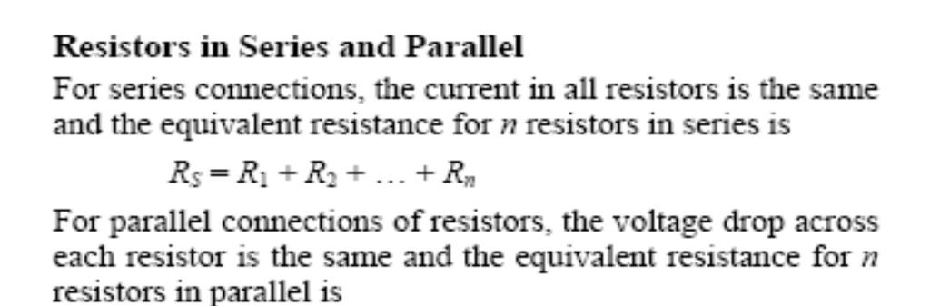
14 esistors Series esistors in series add This type of circuit is a voltage divider if resistors are equal the intermediate voltage will be half 3 tot I ) ( ) ( ) ( I I I I tot tot
15 esistors - Parallel esistors in parallel add inverse This type of circuit is a current divider if resistances are equal, current down one leg is half of the current of a single resistor I I tot tot tot n I I tot... n Itot I I tot
16 oltage divider as the basis for instrumentation Circuits For all resistive sensors, the voltage divider is the primary circuit used in instrumentation esistive sensors are those whose resistance value changes with change in the measured quantity e.g. esistance Temperature Detector (TD) resistance changes with temperature, Strain Gage resistance changes with strain) sensor known sensor sensor Temperature known ( ) Known oltage () Known esistor (known) esistive Sensor (sensor) oltage Measurement Proportional To Sensor alue ()

17 Sensors for Current Two types of sensors are used for current- Ammeters A shunt which is a precision very low resistance resistor over which a voltage drop is observed Typically large blocks of metal to dissipate heat Must cause minimum additional voltage drop typically millivolts A clamp An inductive sensor which surrounds a wire converting the electromagnetic field into a small AC current that can be read by a smaller meter with a shunt Current through only one conductor is measured If put both in the meter, they cancel out
18 Use of Digital Multi Meter (DMM) DMM Using DMM as ammeter Load - - DMM Using DMM as voltmeter or ohmmeter To measure voltage (voltmeter function), measure ACOSS the load In parallel with the load To measure current (ammeter function), you have to measure through the load In series with the load To measure resistance (ohmmeter function), the circuit must be unpowered and then measure across the load You may have to remove the component to get an accurate reading as there may be other paths through the circuit that the ohmmeter function will measure
19 esistor Color Code Color st and nd Band 3rd Band Black 0 x Brown x0 ed x00 Orange 3 x000 Yellow 4 x0,000 Green 5 x00,000 Blue 6 x,000,000 iolet 7 x0,000,000 Gray 8 x00,000,000 White 9 x,000,000,000
20
21 DC Power Power oltage x Current I Since I (Ohms Law), Power also I^ for purely resistive direct current circuits Direct current (DC) where there is no periodic change in voltage or current Alternating current (AC) where there is periodic change in frequency and current Power is in watts A 9 battery with a 000 ohm resistor ( kilo-ohm) across the terminals will have.009 amps running through it which will generate.08 watts A 9 battery with a 0 ohm resistor across it will have.9 amps which will generate 8. watts
22 Capacitors and Inductors Capacitors store electrical energy in static charge Current is a function of the change in voltage with respect to time Often made by a dielectric between two parallel plates Inductors store electrical energy in an electromagnetic field oltage is a function of the change in current Often implemented by a coil of wire Symbol for capacitor Symbol for inductor
23 Introduction To Capacitors Capacitance of a device made from two parallel plates separated by a dielectric is C The dielectric constant times the area of the plate divided by the distance between the plates Capacitance is larger as the area of the plates increases and is smaller as the distance between the plates increases Capacitance measured in FAADS which are very large units of measure. Most electronic circuits uses capacitances in the micro-farad to picofarad range Most batteries are just special capacitors Energy stored in a capacitor One half of the capacitance times the voltage squared E ε A D Symbol for capacitor C
24 Capacitors Can act as integrators and ac filters C Can act as differentiators and DC blocks C
25
26 Alternate Symbol for capacitor
27

28 C Circuit Is like filling a closed tank, current keeps flowing until the tank is full, and then it stops flowing Labview I simulates and predicts this AA Battery.5 olts KiloOhm resistor Ω microfarad capacitor
29
30 Charge-Discharge of a microfarad capacitor with a MegaOhm resistor Discharge initiated at t000 msec
Direct Current (DC) Circuits
 Circuits") Direct Current (DC) Circuits NOTE: There are short answer analysis questions in the Participation section the informal lab report. emember to include these answers in your lab notebook as they will be
Direct Current (DC) Circuits NOTE: There are short answer analysis questions in the Participation section the informal lab report. emember to include these answers in your lab notebook as they will be
Chapter 2. Engr228 Circuit Analysis. Dr Curtis Nelson
 Chapter 2 Engr228 Circuit Analysis Dr Curtis Nelson Chapter 2 Objectives Understand symbols and behavior of the following circuit elements: Independent voltage and current sources; Dependent voltage and
EE301 RESISTANCE AND OHM S LAW
 Learning Objectives a. Describe the concept of resistance b. Use Ohm s law to calculate current, voltage, and resistance values in a circuit c. Discuss the difference between an open circuit and a short
Lecture #3. Review: Power
 Lecture #3 OUTLINE Power calculations Circuit elements Voltage and current sources Electrical resistance (Ohm s law) Kirchhoff s laws Reading Chapter 2 Lecture 3, Slide 1 Review: Power If an element is
Science Olympiad Circuit Lab
 Science Olympiad Circuit Lab Key Concepts Circuit Lab Overview Circuit Elements & Tools Basic Relationships (I, V, R, P) Resistor Network Configurations (Series & Parallel) Kirchhoff s Laws Examples Glossary
EXPERIMENT 12 OHM S LAW
 EXPERIMENT 12 OHM S LAW INTRODUCTION: We will study electricity as a flow of electric charge, sometimes making analogies to the flow of water through a pipe. In order for electric charge to flow a complete
R R V I R. Conventional Current. Ohms Law V = IR
 DC Circuits opics EMF and erminal oltage esistors in Series and in Parallel Kirchhoff s ules EMFs in Series and in Parallel Capacitors in Series and in Parallel Ammeters and oltmeters Conventional Current
Review. Multiple Choice Identify the letter of the choice that best completes the statement or answers the question.
 Review Multiple Choice Identify the letter of the choice that best completes the statement or answers the question. 1. When more devices are added to a series circuit, the total circuit resistance: a.
Chapter 20 Electric Circuits
 Chapter 0 Electric Circuits Chevy olt --- Electric vehicle of the future Goals for Chapter 9 To understand the concept of current. To study resistance and Ohm s Law. To observe examples of electromotive
AP Physics C. Electric Circuits III.C
 AP Physics C Electric Circuits III.C III.C.1 Current, Resistance and Power The direction of conventional current Suppose the cross-sectional area of the conductor changes. If a conductor has no current,
AC vs. DC Circuits. Constant voltage circuits. The voltage from an outlet is alternating voltage
 Circuits AC vs. DC Circuits Constant voltage circuits Typically referred to as direct current or DC Computers, logic circuits, and battery operated devices are examples of DC circuits The voltage from
Direct-Current Circuits. Physics 231 Lecture 6-1
 Direct-Current Circuits Physics 231 Lecture 6-1 esistors in Series and Parallel As with capacitors, resistors are often in series and parallel configurations in circuits Series Parallel The question then
ECE2262 Electric Circuits. Chapter 6: Capacitance and Inductance
 ECE2262 Electric Circuits Chapter 6: Capacitance and Inductance Capacitors Inductors Capacitor and Inductor Combinations Op-Amp Integrator and Op-Amp Differentiator 1 CAPACITANCE AND INDUCTANCE Introduces
Physics 115. General Physics II. Session 24 Circuits Series and parallel R Meters Kirchoff s Rules
 Physics 115 General Physics II Session 24 Circuits Series and parallel R Meters Kirchoff s Rules R. J. Wilkes Email: phy115a@u.washington.edu Home page: http://courses.washington.edu/phy115a/ 5/15/14 Phys
AP Physics C - E & M
 AP Physics C - E & M Current and Circuits 2017-07-12 www.njctl.org Electric Current Resistance and Resistivity Electromotive Force (EMF) Energy and Power Resistors in Series and in Parallel Kirchoff's
Some Important Electrical Units
 Some Important Electrical Units Quantity Unit Symbol Current Charge Voltage Resistance Power Ampere Coulomb Volt Ohm Watt A C V W W These derived units are based on fundamental units from the meterkilogram-second
LABORATORY 4 ELECTRIC CIRCUITS I. Objectives
 LABORATORY 4 ELECTRIC CIRCUITS I Objectives to be able to discuss potential difference and current in a circuit in terms of electric field, work per unit charge and motion of charges to understand that
Physics 7B-1 (A/B) Professor Cebra. Winter 2010 Lecture 2. Simple Circuits. Slide 1 of 20
 Professor Cebra. Winter 2010 Lecture 2. Simple Circuits. Slide 1 of 20") Physics 7B-1 (A/B) Professor Cebra Winter 2010 Lecture 2 Simple Circuits Slide 1 of 20 Conservation of Energy Density In the First lecture, we started with energy conservation. We divided by volume (making
Physics 7B-1 (A/B) Professor Cebra Winter 2010 Lecture 2 Simple Circuits Slide 1 of 20 Conservation of Energy Density In the First lecture, we started with energy conservation. We divided by volume (making
Notes on Electricity (Circuits)
") A circuit is defined to be a collection of energy-givers (active elements) and energy-takers (passive elements) that form a closed path (or complete path) through which electrical current can flow. The
A circuit is defined to be a collection of energy-givers (active elements) and energy-takers (passive elements) that form a closed path (or complete path) through which electrical current can flow. The
1) Two lightbulbs, one rated 30 W at 120 V and another rated 40 W at 120 V, are arranged in two different circuits.
 Two lightbulbs, one rated 30 W at 120 V and another rated 40 W at 120 V, are arranged in two different circuits.") 1) Two lightbulbs, one rated 30 W at 120 V and another rated 40 W at 120 V, are arranged in two different circuits. a. The two bulbs are first connected in parallel to a 120 V source. i. Determine the
1) Two lightbulbs, one rated 30 W at 120 V and another rated 40 W at 120 V, are arranged in two different circuits. a. The two bulbs are first connected in parallel to a 120 V source. i. Determine the
CHEM*3440. Current Convention. Charge. Potential Energy. Chemical Instrumentation. Rudimentary Electronics. Topic 3
 urrent onvention HEM*3440 hemical nstrumentation Topic 3 udimentary Electronics ONENTON: Electrical current flows from a region of positive potential energy to a region of more negative (or less positive)
Electricity. From the word Elektron Greek for amber
 Electricity From the word Elektron Greek for amber Electrical systems have two main objectives: To gather, store, process, transport information & Energy To distribute and convert energy Electrical Engineering
Lecture Outline Chapter 21. Physics, 4 th Edition James S. Walker. Copyright 2010 Pearson Education, Inc.
 Lecture Outline Chapter 21 Physics, 4 th Edition James S. Walker Chapter 21 Electric Current and Direct- Current Circuits Units of Chapter 21 Electric Current Resistance and Ohm s Law Energy and Power
Lab #6 Ohm s Law. Please type your lab report for Lab #6 and subsequent labs.
 Dr. Day, Fall 2004, Rev. 06/22/10 HEFW PH 262 Page 1 of 4 Lab #6 Ohm s Law Please type your lab report for Lab #6 and subsequent labs. Objectives: When you have completed this lab exercise you should be
in series Devices connected in series will have the same amount of charge deposited on each capacitor. But different potential difference. That means
 Electric Field Electricity Lecture Series Electric Field: Field an area where any charged object will experience an electric force Kirchoff s Laws The electric field lines around a pair of point charges
Syllabus and Course Overview!
 Electronics Lab! Syllabus and Course Overview! oltage Current and Ohm s Law! Kirchoff s Laws! The oltage Divider! Syllabus and Course Overview! n http://www.stlawu.edu/academics/programs/physics! oltage,
16.1 Electrical Current
 16.1 Electrical Current Electric Current Electric Current When the ends of an electric conductor are at different electric potentials, charge flows from one end to the other Flow of Charge Charge flows
BASIC ELECTRONICS PROF. T.S. NATARAJAN DEPT OF PHYSICS IIT MADRAS LECTURE-3 ELECTRONIC DEVICES -II RESISTOR SERIES & PARALLEL
 BASIC ELECTRONICS PROF. T.S. NATARAJAN DEPT OF PHYSICS IIT MADRAS LECTURE-3 ELECTRONIC DEVICES -II RESISTOR SERIES & PARALLEL Hello everybody we are doing a course on basic electronics by the method of
2. The following diagram illustrates that voltage represents what physical dimension?
 BioE 1310 - Exam 1 2/20/2018 Answer Sheet - Correct answer is A for all questions 1. A particular voltage divider with 10 V across it consists of two resistors in series. One resistor is 7 KΩ and the other
ECE2262 Electric Circuits. Chapter 6: Capacitance and Inductance
 ECE2262 Electric Circuits Chapter 6: Capacitance and Inductance Capacitors Inductors Capacitor and Inductor Combinations 1 CAPACITANCE AND INDUCTANCE Introduces two passive, energy storing devices: Capacitors
DEPARTMENT OF COMPUTER ENGINEERING UNIVERSITY OF LAHORE
 DEPARTMENT OF COMPUTER ENGINEERING UNIVERSITY OF LAHORE NAME. Section 1 2 3 UNIVERSITY OF LAHORE Department of Computer engineering Linear Circuit Analysis Laboratory Manual 2 Compiled by Engr. Ahmad Bilal
Resistivity and Temperature Coefficients (at 20 C)
") Homework # 4 Resistivity and Temperature Coefficients (at 0 C) Substance Resistivity, Temperature ( m) Coefficient, (C ) - Conductors Silver.59 x 0-0.006 Copper.6 x 0-0.006 Aluminum.65 x 0-0.0049 Tungsten
Homework # 4 Resistivity and Temperature Coefficients (at 0 C) Substance Resistivity, Temperature ( m) Coefficient, (C ) - Conductors Silver.59 x 0-0.006 Copper.6 x 0-0.006 Aluminum.65 x 0-0.0049 Tungsten
Electrical Engineering Fundamentals for Non-Electrical Engineers
 Electrical Engineering Fundamentals for Non-Electrical Engineers by Brad Meyer, PE Contents Introduction... 3 Definitions... 3 Power Sources... 4 Series vs. Parallel... 9 Current Behavior at a Node...
Notes on Electricity (Circuits)
") A circuit is defined to be a collection of energy-givers (batteries) and energy-takers (resistors, light bulbs, radios, etc.) that form a closed path (or complete path) through which electrical current
A circuit is defined to be a collection of energy-givers (batteries) and energy-takers (resistors, light bulbs, radios, etc.) that form a closed path (or complete path) through which electrical current
Physics 2401 Summer 2, 2008 Exam II
 Physics 2401 Summer 2, 2008 Exam II e = 1.60x10⁻¹⁹ C, m(electron) = 9.11x10⁻³¹ kg, ε 0 = 8.845x10⁻¹² C 2 /Nm 2, k e = 9.0x10 9 Nm 2 /C 2, m(proton) = 1.67x10⁻²⁷ kg. n = nano = 10-9, µ = micro = 10-6, m
PHY102 Electricity Course Summary
 TOPIC 1 ELECTOSTTICS PHY1 Electricity Course Summary Coulomb s Law The magnitude of the force between two point charges is directly proportional to the product of the charges and inversely proportional
CAPACITORS / ENERGY STORED BY CAPACITORS / CHARGING AND DISCHARGING
 PHYSICS A2 UNIT 4 SECTION 3: CAPACITANCE CAPACITORS / ENERGY STORED BY CAPACITORS / CHARGING AND DISCHARGING # Question CAPACITORS 1 What is current? Current is the rate of flow of charge in a circuit
Circuits. 1. The Schematic
 + ircuits 1. The Schematic 2. Power in circuits 3. The Battery 1. eal Battery vs. Ideal Battery 4. Basic ircuit nalysis 1. oltage Drop 2. Kirchoff s Junction Law 3. Series & Parallel 5. Measurement Tools
Electric Currents and Circuits
 Nicholas J. Giordano www.cengage.com/physics/giordano Chapter 19 Electric Currents and Circuits Marilyn Akins, PhD Broome Community College Electric Circuits The motion of charges leads to the idea of
SIMPLE D.C. CIRCUITS AND MEASUREMENTS Background
 SIMPLE D.C. CICUITS AND MEASUEMENTSBackground This unit will discuss simple D.C. (direct current current in only one direction) circuits: The elements in them, the simple arrangements of these elements,
Chapter 26 Direct-Current and Circuits. - Resistors in Series and Parallel - Kirchhoff s Rules - Electric Measuring Instruments - R-C Circuits
 Chapter 26 Direct-Current and Circuits - esistors in Series and Parallel - Kirchhoff s ules - Electric Measuring Instruments - -C Circuits . esistors in Series and Parallel esistors in Series: V ax I V
Electric Currents. Resistors (Chapters 27-28)
") Electric Currents. Resistors (Chapters 27-28) Electric current I Resistance R and resistors Relation between current and resistance: Ohm s Law Resistivity ρ Energy dissipated by current. Electric power
Electric Currents. Resistors (Chapters 27-28) Electric current I Resistance R and resistors Relation between current and resistance: Ohm s Law Resistivity ρ Energy dissipated by current. Electric power
ELECTRICITY. Electric Circuit. What do you already know about it? Do Smarty Demo 5/30/2010. Electric Current. Voltage? Resistance? Current?
 ELECTRICITY What do you already know about it? Voltage? Resistance? Current? Do Smarty Demo 1 Electric Circuit A path over which electrons travel, out through the negative terminal, through the conductor,
Capacitor Construction
 Capacitor Construction Topics covered in this presentation: Capacitor Construction 1 of 13 Introduction to Capacitors A capacitor is a device that is able to store charge and acts like a temporary, rechargeable
Physics 1402: Lecture 10 Today s Agenda
 Physics 1402: Lecture 10 Today s Agenda Announcements: Lectures posted on: www.phys.uconn.edu/~rcote/ HW assignments, solutions etc. Homework #3: On Masterphysics : due Friday at 8:00 AM Go to masteringphysics.com
Capacitance. A different kind of capacitor: Work must be done to charge a capacitor. Capacitors in circuits. Capacitor connected to a battery
 Capacitance The ratio C = Q/V is a conductor s self capacitance Units of capacitance: Coulomb/Volt = Farad A capacitor is made of two conductors with equal but opposite charge Capacitance depends on shape
Practical 1 RC Circuits
 Objectives Practical 1 Circuits 1) Observe and qualitatively describe the charging and discharging (decay) of the voltage on a capacitor. 2) Graphically determine the time constant for the decay, τ =.
Electric Charges & Current. Chapter 12. Types of electric charge
 Electric Charges & Current Chapter 12 Types of electric charge Protons w/ + charge stuck in the nucleus Electrons w/ - charge freely moving around the nucleus in orbits 1 Conductors Allow the easy flow
Electric Currents and Circuits
 Electric Currents and Circuits Producing Electric Current Electric Current flow of charged particles Need a potential difference to occur Conventional Current- flow of positive charges flowing from positive
ENERGY AND TIME CONSTANTS IN RC CIRCUITS By: Iwana Loveu Student No Lab Section: 0003 Date: February 8, 2004
 ENERGY AND TIME CONSTANTS IN RC CIRCUITS By: Iwana Loveu Student No. 416 614 5543 Lab Section: 0003 Date: February 8, 2004 Abstract: Two charged conductors consisting of equal and opposite charges forms
SPS Presents: A Cosmic Lunch!
 SPS Presents: A Cosmic Lunch! Who: Dr. Brown will be speaking about Evolution of the Elements: from Periodic table to Standard Model and Beyond! When: October 7 th at am Where: CP 79 (by the front office)
Introduction to AC Circuits (Capacitors and Inductors)
") Introduction to AC Circuits (Capacitors and Inductors) Amin Electronics and Electrical Communications Engineering Department (EECE) Cairo University elc.n102.eng@gmail.com http://scholar.cu.edu.eg/refky/
Introduction to AC Circuits (Capacitors and Inductors) Amin Electronics and Electrical Communications Engineering Department (EECE) Cairo University elc.n102.eng@gmail.com http://scholar.cu.edu.eg/refky/
SECTION 3 BASIC AUTOMATIC CONTROLS UNIT 12 BASIC ELECTRICITY AND MAGNETISM
 SECTION 3 BASIC AUTOMATIC CONTROLS UNIT 12 BASIC ELECTRICITY AND MAGNETISM Unit Objectives Describe the structure of an atom. Identify atoms with a positive charge and atoms with a negative charge. Explain
Coulomb s constant k = 9x10 9 N m 2 /C 2
 1 Part 2: Electric Potential 2.1: Potential (Voltage) & Potential Energy q 2 Potential Energy of Point Charges Symbol U mks units [Joules = J] q 1 r Two point charges share an electric potential energy
DC Circuits. Electromotive Force Resistor Circuits. Kirchoff s Rules. RC Circuits. Connections in parallel and series. Complex circuits made easy
 DC Circuits Electromotive Force esistor Circuits Connections in parallel and series Kirchoff s ules Complex circuits made easy C Circuits Charging and discharging Electromotive Force (EMF) EMF, E, is the
Circuits. Electric Current & DC Circuits Circuits. Unit 6. April Electric Current. Electric Current. Electric Current. ΔQ Δt
 Electric Current & DC Circuits Electric Current & DC Circuits Circuits Conductors esistivity and esistance Click on the topic to go to that section Circuit Diagrams Measurement Electric Current Circuits
CHAPTER INTRODUCTION TO ELECTRIC CIRCUITS. C h a p t e r INTRODUCTION
 C h a p t e r CHAPTE NTODUCTON TO ELECTC CCUTS.0 NTODUCTON This chapter is explaining about the basic principle of electric circuits and its connections. The learning outcome for this chapter are the students
I depicted in Figure 1. When a current of I amps (A) flows through the resistor, a voltage drop V AB volts (V) appears across the terminals A and B.
 flows through the resistor, a voltage drop V AB volts (V) appears across the terminals A and B.") ntroduction to DC Circuits v 0.92: September 20, 2018 Gerald ecktenwald gerry@pdx.edu 1 ntroduction Engineers from all disciplines need to have working knowledge of basic electrical circuits. These notes
ntroduction to DC Circuits v 0.92: September 20, 2018 Gerald ecktenwald gerry@pdx.edu 1 ntroduction Engineers from all disciplines need to have working knowledge of basic electrical circuits. These notes
Direct Current (DC): In a DC circuit the current and voltage are constant as a function of time. Power (P): Rate of doing work P = dw/dt units = Watts
: In a DC circuit the current and voltage are constant as a function of time. Power (P): Rate of doing work P = dw/dt units = Watts") Lecture 1: Introduction Some Definitions: Current (I): Amount of electric charge (Q) moving past a point per unit time I dq/dt Coulombs/sec units Amps (1 Coulomb 6x10 18 electrons) oltage (): Work needed
Lecture 1: Introduction Some Definitions: Current (I): Amount of electric charge (Q) moving past a point per unit time I dq/dt Coulombs/sec units Amps (1 Coulomb 6x10 18 electrons) oltage (): Work needed
Basic Electronics. Introductory Lecture Course for. Technology and Instrumentation in Particle Physics Chicago, Illinois June 9-14, 2011
 Basic Electronics Introductory Lecture Course for Technology and Instrumentation in Particle Physics 2011 Chicago, Illinois June 9-14, 2011 Presented By Gary Drake Argonne National Laboratory drake@anl.gov
Chapter 26 & 27. Electric Current and Direct- Current Circuits
 Chapter 26 & 27 Electric Current and Direct- Current Circuits Electric Current and Direct- Current Circuits Current and Motion of Charges Resistance and Ohm s Law Energy in Electric Circuits Combination
Lecture #2 Charge, Current, Energy, Voltage Power Kirchhoff s Current Law Kirchhoff s Voltage Law
 EECS 42 Introduction to Electronics for Computer Science Andrew R. Neureuther Lecture #2 Charge, Current, Energy, Voltage Power Kirchhoff s Current Law Kirchhoff s Voltage Law Corrections Slide 3 and 9
Chapter 17. Current and Resistance. Sections: 1, 3, 4, 6, 7, 9
 Chapter 17 Current and Resistance Sections: 1, 3, 4, 6, 7, 9 Equations: 2 2 1 e r q q F = k 2 e o r Q k q F E = = I R V = A L R ρ = )] ( 1 [ o o T T + = α ρ ρ V I V t Q P = = R V R I P 2 2 ) ( = = C Q
Electrical measurements:
 Electrical measurements: Last time we saw that we could define circuits though: current, voltage and impedance. Where the impedance of an element related the voltage to the current: This is Ohm s law.
UNIVERSITY OF TECHNOLOGY, JAMAICA Faculty of Engineering and Computing School of Engineering
 UNIVERSITY OF TECHNOLOGY, JAMAICA Faculty of Engineering and Computing School of Engineering SYLLABUS OUTLINE FACULTY: SCHOOL/DEPT: COURSE OF STUDY: Engineering and Computing Engineering Diploma in Electrical
Introduction to Electric Circuit Analysis
 EE110300 Practice of Electrical and Computer Engineering Lecture 2 and Lecture 4.1 Introduction to Electric Circuit Analysis Prof. Klaus Yung-Jane Hsu 2003/2/20 What Is An Electric Circuit? Electrical
Electricity Review completed.notebook. June 13, 2013
 Which particle in an atom has no electric charge associated with it? a. proton c. neutron b. electron d. nucleus Jun 12 9:28 PM The electrons in a metal sphere can be made to move by touching it with a
Current Electricity. ScienceLinks 9, Unit 4 SciencePower 9, Unit 3
 Current Electricity ScienceLinks 9, Unit 4 SciencePower 9, Unit 3 Current Electricity The flow of negative charges (electrons) through conductors Watch the BrainPOPs: Electricity Current Electricity Activity:
ENGR 2405 Chapter 6. Capacitors And Inductors
 ENGR 2405 Chapter 6 Capacitors And Inductors Overview This chapter will introduce two new linear circuit elements: The capacitor The inductor Unlike resistors, these elements do not dissipate energy They
Electric Charge. Electric Charge ( q ) unbalanced charges positive and negative charges. n Units Coulombs (C)
 unbalanced charges positive and negative charges. n Units Coulombs (C)") Electric Charge Electric Charge ( q ) unbalanced charges positive and negative charges n Units Coulombs (C) Electric Charge How do objects become charged? Types of materials Conductors materials in which
Electric Charge Electric Charge ( q ) unbalanced charges positive and negative charges n Units Coulombs (C) Electric Charge How do objects become charged? Types of materials Conductors materials in which
Electric Circuits. AP Physics 1
 Electric Circuits AP Physics Potential Difference =oltage=emf n a battery, a series of chemical reactions occur in which electrons are transferred from one terminal to another. There is a potential difference
2. Basic Components and Electrical Circuits
 1 2. Basic Components and Electrical Circuits 2.1 Units and Scales The International System of Units (SI) defines 6 principal units from which the units of all other physical quantities can be derived
ET 162 Circuit Analysis. Current and Voltage. Electrical and Telecommunication Engineering Technology. Professor Jang
 ET 162 Circuit Analysis Current and Voltage Electrical and Telecommunication Engineering Technology Professor Jang Acknowledgement I want to express my gratitude to Prentice Hall giving me the permission
ES250: Electrical Science. HW1: Electric Circuit Variables, Elements and Kirchhoff s Laws
 ES250: Electrical Science HW1: Electric Circuit Variables, Elements and Kirchhoff s Laws Introduction Engineers use electric circuits to solve problems that are important to modern society, such as: 1.
Insulators Non-metals are very good insulators; their electrons are very tightly bonded and cannot move.
 SESSION 11: ELECTRIC CIRCUITS Key Concepts Resistance and Ohm s laws Ohmic and non-ohmic conductors Series and parallel connection Energy in an electric circuit X-planation 1. CONDUCTORS AND INSULATORS
[1] (b) Fig. 1.1 shows a circuit consisting of a resistor and a capacitor of capacitance 4.5 μf. Fig. 1.1
![[1] (b) Fig. 1.1 shows a circuit consisting of a resistor and a capacitor of capacitance 4.5 μf. Fig. 1.1](/thumbs/81/83276652.jpg "[1] (b) Fig. 1.1 shows a circuit consisting of a resistor and a capacitor of capacitance 4.5 μf. Fig. 1.1") 1 (a) Define capacitance..... [1] (b) Fig. 1.1 shows a circuit consisting of a resistor and a capacitor of capacitance 4.5 μf. S 1 S 2 6.3 V 4.5 μf Fig. 1.1 Switch S 1 is closed and switch S 2 is left
1 (a) Define capacitance..... [1] (b) Fig. 1.1 shows a circuit consisting of a resistor and a capacitor of capacitance 4.5 μf. S 1 S 2 6.3 V 4.5 μf Fig. 1.1 Switch S 1 is closed and switch S 2 is left
Electricity and Light Pre Lab Questions
 Electricity and Light Pre Lab Questions The pre lab questions can be answered by reading the theory and procedure for the related lab. You are strongly encouraged to answers these questions on your own.
The Basic Capacitor. Dielectric. Conductors
 Chapter 9 The Basic Capacitor Capacitors are one of the fundamental passive components. In its most basic form, it is composed of two conductive plates separated by an insulating dielectric. The ability
Physics 214 Spring
 Lecture 23 March 4 2016 The elation between Voltage Differences V and Voltages V? Current Flow, Voltage Drop on esistors and Equivalent esistance Case 1: Series esistor Combination and esulting Currents
Closed loop of moving charges (electrons move - flow of negative charges; positive ions move - flow of positive charges. Nucleus not moving)
") Unit 2: Electricity and Magnetism Lesson 3: Simple Circuits Electric circuits transfer energy. Electrical energy is converted into light, heat, sound, mechanical work, etc. The byproduct of any circuit
Unit 2: Electricity and Magnetism Lesson 3: Simple Circuits Electric circuits transfer energy. Electrical energy is converted into light, heat, sound, mechanical work, etc. The byproduct of any circuit
Capacitors are devices which can store electric charge. They have many applications in electronic circuits. They include:
 CAPACITORS Capacitors are devices which can store electric charge They have many applications in electronic circuits They include: forming timing elements, waveform shaping, limiting current in AC circuits
Chapter 16. Current and Drift Speed. Electric Current, cont. Current and Drift Speed, cont. Current and Drift Speed, final
 Chapter 6 Current, esistance, and Direct Current Circuits Electric Current Whenever electric charges of like signs move, an electric current is said to exist The current is the rate at which the charge
Greek Letter Omega Ω = Ohm (Volts per Ampere)
") ) What is electric current? Flow of Electric Charge 2) What is the unit we use for electric current? Amperes (Coulombs per Second) 3) What is electrical resistance? Resistance to Electric Current 4) What
) What is electric current? Flow of Electric Charge 2) What is the unit we use for electric current? Amperes (Coulombs per Second) 3) What is electrical resistance? Resistance to Electric Current 4) What
7/06 Electric Fields and Energy
 Part ASome standard electric field and potential configurations About this lab: Electric fields are created by electric charges and exert force on charges. Electric potential gives an alternative description.
M. C. Escher: Waterfall. 18/9/2015 [tsl425 1/29]
![M. C. Escher: Waterfall. 18/9/2015 [tsl425 1/29]](/thumbs/76/73138710.jpg "M. C. Escher: Waterfall. 18/9/2015 [tsl425 1/29]") M. C. Escher: Waterfall 18/9/2015 [tsl425 1/29] Direct Current Circuit Consider a wire with resistance R = ρl/a connected to a battery. Resistor rule: In the direction of I across a resistor with resistance
M. C. Escher: Waterfall 18/9/2015 [tsl425 1/29] Direct Current Circuit Consider a wire with resistance R = ρl/a connected to a battery. Resistor rule: In the direction of I across a resistor with resistance
Chapter 2 Circuit Elements
 hapter ircuit Elements hapter ircuit Elements.... Introduction.... ircuit Element onstruction....3 esistor....4 Inductor... 4.5 apacitor... 6.6 Element Basics... 8.6. Element eciprocals... 8.6. eactance...
Pretest ELEA1831 Module 11 Units 1& 2 Inductance & Capacitance
 Pretest ELEA1831 Module 11 Units 1& 2 Inductance & Capacitance 1. What is Faraday s Law? Magnitude of voltage induced in a turn of wire is proportional to the rate of change of flux passing through that
Man Struck By Lightning: Faces Battery Charge. Electricity
 Man Struck By Lightning: Faces Battery Charge Electricity Properties of Electric Charge (Elektrisk ladning) Electric charges (q) repel or attract each other Like charges repel Opposite charges attract
Chapter 21 Electric Current and Direct- Current Circuits
 Chapter 21 Electric Current and Direct- Current Circuits 1 Overview of Chapter 21 Electric Current and Resistance Energy and Power in Electric Circuits Resistors in Series and Parallel Kirchhoff s Rules
Ohm s Law and Electronic Circuits
 Production Ohm s Law and Electronic Circuits Page 1 - Cyber Security Class ELECTRICAL CIRCUITS All you need to be an inventor is a good imagination and a pile of junk. -Thomas Edison Page 2 - Cyber Security
National 5 Physics. Electricity and Energy. Notes
 National 5 Physics Electricity and Energy Notes Name. 1 P a g e Key Area Notes, Examples and Questions Page 3 Conservation of energy Page 10 Electrical charge carriers and electric fields and potential
Chapter 7 Direct-Current Circuits
 Chapter 7 Direct-Current Circuits 7. Introduction... 7. Electromotive Force... 7.3 Resistors in Series and in Parallel... 4 7.4 Kirchhoff s Circuit Rules... 6 7.5 Voltage-Current Measurements... 8 7.6
Lecture 1. Electrical Transport
 Lecture 1. Electrical Transport 1.1 Introduction * Objectives * Requirements & Grading Policy * Other information 1.2 Basic Circuit Concepts * Electrical l quantities current, voltage & power, sign conventions
Unit 3 BLM Answers UNIT 3 BLM 3-46
 UNIT 3 BLM 3-46 Unit 3 BLM Answers BLM 3-3, Charge Transfer Diagrams 1. Positively charged objects should have more (+) than ( ). Negatively charged objects should have more ( ) than (+). 2. They must
Chapter 33 - Electric Fields and Potential. Chapter 34 - Electric Current
 Chapter 33 - Electric Fields and Potential Chapter 34 - Electric Current Electric Force acts through a field An electric field surrounds every electric charge. It exerts a force that causes electric charges
Monday July 14. Capacitance demo slide 19 Capacitors in series and parallel slide 33 Elmo example
 Monday July 14 Lecture 5 Capacitance demo slide 19 Capacitors in series and parallel slide 33 Elmo example Lecture 6 Currents and esistance Lecture 9 Circuits Wear Microphone 1 3 Lecture 6 Current and
FE Review 2/2/2011. Electric Charge. Electric Energy ELECTRONICS # 1 FUNDAMENTALS
 FE eview ELECONICS # FUNDAMENALS Electric Charge 2 In an electric circuit there is a conservation of charge. he net electric charge is constant. here are positive and negative charges. Like charges repel
Electric Current. Chapter 17. Electric Current, cont QUICK QUIZ Current and Resistance. Sections: 1, 3, 4, 6, 7, 9
 Electric Current Chapter 17 Current and Resistance Sections: 1, 3, 4, 6, 7, 9 Whenever electric charges of like signs move, an electric current is said to exist The current is the rate at which the charge
Chapter 3: Electric Current and Direct-Current Circuit
 Chapter 3: Electric Current and Direct-Current Circuit n this chapter, we are going to discuss both the microscopic aspect and macroscopic aspect of electric current. Direct-current is current that flows
Topic 5.2 Heating Effect of Electric Currents
 Topic 5.2 Heating Effect of Electric Currents Kari Eloranta 2017 Jyväskylän Lyseon lukio International Baccalaureate February 14, 2017 Topic 5.2 Heating Effect of Electric Currents In subtopic 5.2 we study