Prediction of Wing Flutter Boundary Using High Fidelity Delayed Detached Eddy Simulation
|
|
|
- Moris Smith
- 5 years ago
- Views:
Transcription
1 SciTech January, 15, Kissimmee, FL 53rd AIAA Aerospace Sciences Meeting AIAA Prediction of Wing Flutter Boundary Using High Fidelity Delayed Detached Eddy Simulation Jia-ye Gan, Hong-Sik, Im Xiang-ying, Chen, Ge-Cheng Zha Dept. of Mechanical and Aerospace Engineering University of Miami Coral Gables, Florida 3314 Crystal L. Pasiliao AFRL/RWWV, Munition Aerodynamic Sciences Branch 11 West Eglin Blvd, Suite 33 Eglin AFB FL 354 Abstract This paper conducts Delayed Detached Eddy Simulation(DDES) of a 3D wing flutter with free stream Mach number varied from subsonic to supersonic using a fully coupled fluid/structure interaction (FSI). Unsteady 3D compressible Navier-Stokes equations are solved with a system of 5 decoupled structure modal equations in a fully coupled manner. The low diffusion E-CUSP scheme with a 5th order WENO reconstruction for the inviscid flux and a set of nd order central differencing for the viscous terms are used to accurately capture the shock wave/turbulent boundary layer interaction of the vibrating wing. The predicted flutter boundaries at different free stream Mach numbers achieve very good agreement with experiment. It appears that the transonic dip phenomenon is due to the anticlimax contribution of the second mode, which is caused by the complicated shock oscillation on the wing.at the flutter boundary including at the sonic dip, no flow separation due to shock/boundary layer interaction is observed. PhD Student, AIAA Member PhD., Currently a senior engineer at Honeywell PhD., Research Associate Professor Professor, AIAA Associate Fellow, gzha@miami.edu PhD., Basic Research Lead Copyright c 15 by all the authors of this article. Published by the American Institute of Aeronautics and Astronautics, Inc., with permission. 1
2 Nomenclature d = distance from the closest wall f d = delayed LES function in DDES J = Jacobian of the coordinate transformation I = identity matrix ξ t, η t, ζ t = ξ, η, ζ component of grid moving velocity U, V, W = ξ, η, ζ component of contravariant velocity U i,j = velocity gradient x, y, z = Cartesian coordinates δ ij = Kronecker delta Pr = Prandtl number Pr t = turbulent Prandtl number ν = kinematic viscosity δ x = x-component of displacements of the structure surface δ y = y-component of displacements of the structure surface δ z = z-component of displacements of the structure surface ξ, η, ζ = generalized coordinates Subscripts i, j, k = indices = reference variable at free stream Flutter parameters b s = wing root semi-chord m = wing panel mass V = frustum volume V = U reduced velocity, b sω α V f = flutter speed index, V µ ω α = 1st torsional mode natural frequency µ = m mass ratio, V ρ ω j = natural frequency for jth mode ζ j = modal damping ratio for jth mode Abbreviations CUSP = convective upwind and split pressure DES = detached eddy simulation DDES = delayed detached eddy simulation FSI = fluid/structure interaction WENO = weighted essentially non-oscillatory 1 Introduction Flutter is a self-excited aeroelastic instability which occurs when the aerodynamic damping is negative, and could lead to structural failure. Flutter is a critical problem in aeroelastic design and should be considered in the early phase of aircraft structural design. Experimental testing of aircraft aeroelasticity is very expensive in the design phase. Therefore, tools for aerodynamic flutter prediction are very important to succeed in aircraft design. Flutter may occur at subsonic and supersonic speed. There are complicated flow phenomena such
3 as flow separation and shock wave/turbulent boundary layer interaction(stbli) during flutter. Physical models had been developed to predict the flutter boundary of aircraft. The classical linear models[1] including piston theory and full potential model are widely used in aeroelastic design for the advantage of computational efficiency. The disadvantage of linear modes is that they fail to capture the location and magnitude of local shock motion in transonic and supersonic regime. To predict the transonic or supersonic flutter boundary with higher accuracy, tools based on Euler equations have been developed. Bendiksen et al.[] study the transonic flutter of typical section wing models by solving the Euler equation coupled with a two degrees of freedom of structural dynamic equations. Reasonably flutter results were obtained in the regions where there are no strong shock. Rausch et al.[3] predict flutter boundary of a set of configuration by solving unsteady Euler aerodynamic equations on unstructured grid. Good agreement was obtained in flutter boundary for subsonic flow. However the predicted flutter characteristics on transonic flow were not satisfactory. Since the the viscous effect on flutter boundary are neglected, neither potential model nor Euler equations are suitable for understanding the STBLI and the mechanism of transonic dip. Prananta et al.[4] reported the results of aeroelastic simulations by using the Euler and the Navier-Stokes solvers. Their calculations show that the viscous effect plays an extremely important role in determining the transonic dip and flutter boundary for a NACA64A1 airfoil. Lee-Rausch et al.[5] also study the effect of viscosity on the flutter boundary of AGARD wing by comparing the Euler and Navier-Stokes results over a range of Mach numbers from.499 to Their calculation shows a significant viscous effect on the supersonic flutter boundary, and the Euler flutter result is quiet different from the Navier-Stokes one on the supersonic side. Viscous effects can move the shock wave location and the STBLI may induce large separation that change the flutter speed. The drop of transonic flutter boundary is considered due to the presence of part chord shock and its oscillation that is not in phase with the airfoil motion[6]. To understand the mechanism of this non-linear behavior, high fidelity solver based on Navier-Stokes equations coupled with the structural dynamic governing equations is required. Computational methods using Reynolds Averaged Navier Stokes (RANS)[7, 8], large eddy simulation (LES)[9], and direct numerical simulation (DNS)[7, 1] have been utilized to study the STBLI. DNS and LES provide better comparison with experimental results than RANS. Priebe et al[1] employed DNS to study the STBLI on a ramp configuration. They demonstrate that the shock impingement amplifies the pressure fluctuation and there are high-level, low-frequency (< 1 Hz) vortex structures in the turbulent boundary layer. However, DNS and LES require extremely expensive computational cost. Hence DNS and LES are seldom used in the study the STBLI coupled with the structural vibration. On the other hand, RANS cannot accurately capture the shock oscillation due to the interaction with the turbulent boundary layer without shock unsteadiness correction[9]. The hybrid RANS/LES approach, Detached eddy simulation (DES) suggested by Spalart[11], is developed for complex turbulence problem. DES is designed to take the advantages of RANS and LES methods. In DES, a RANS model is used in the near wall regions to reduce the grid density, and the LES is used outside the near wall regions, which is capable of dealing with massively separated flows. Recently, Chen et al.[1] predict the transonic flutter boundary of AGARD wing model by using delayed-detached-eddy simulation(ddes)[11]. In their study, time accurate Navier-Stokes equations are solved with a system of N-decoupled structure modal equations in a fully coupled manner[13, 14]. The computed transonic flutter boundary agrees very well with the experiment. The same method was performed by Im et al.[15] to predict the supersonic flutter boundary of the AGARD wing model. Their results appear to be the first time that a numerical prediction of supersonic flutter boundary matches with experiment accurately. The flutter mechanisms in transonic and supersonic condition are not shown in detail in [1, 15]. Furthermore, the complete AGARD wing flutter boundary at different Mach numbers from subsonic to supersonic is not provided in their work. The purpose of this paper is to calculate the full AGARD wing flutter boundary and investigate the flutter mechanism using high fidelity DDES with a fully coupled FSI. 3
4 Numerical Model for Fluid Flow.1 Navier-Stokes Equations The spatially filtered unsteady compressible Navier-Stokes equations governing the viscous flow over the 3D wing can be written in a normalized form in the generalized coordinates(ξ, η, ζ). ( ) Q t + E ξ + F η + G ζ = 1 Ev Re ξ + Fv η + Gv ζ where Re is the Reynolds number. The equations are non-dimensionalized based on airfoil chord L, free stream density ρ, velocity U, and viscosity µ. The conservative variable vector Q, the inviscid flux vectors E, F, G, and the viscous flux E v, F v, G v are expressed as Q = 1 J ρ ρũ ρṽ ρ w ρẽ,e = E v = ρu ρũu + l x p ρṽu + l y p ρ wu + l z p ( ρẽ + p) U l t p l k τ xk l k τ yk l k τ zk l k (ũ i τ ki q k ),F v =,F = ρv ρũv + m x p ρṽv + m y p ρ wv + m z p ( ρẽ + p) V m t p m k τu xk m k τ yk m k τu zk m k (ũ i τ ki q k ),G v =,G = ρw ρũw + n x p ρṽw + n y p ρ ww + n z p ( ρẽ + p)w n t p n k τ xk n k τ yk n k τ zk n k (ũ i τ ki q k ) where ρ is the density, p is the static pressure, and e is the total energy per unit mass. The overbar denotes a regular filtered variable, and the tilde is used to denote the Favre filtered variable, ν is kinematic viscosity and ν is the working variable related to eddy viscosity in S-A model. U, V and W are the contravariant velocities in ξ, η, ζ directions, and are defined as U = l t + l V = l t + l x ũ + l y ṽ + l z w (4) V = m t + m V = m t + m x ũ + m y ṽ + m z w (5) W = n t + n V = n t + n x ũ + n y ṽ + n z w (6) where J is the Jacobian of the coordinate transformation. l t, m t and n t are the components of the interface contravariant velocity of the control volume in ξ, η and ζ directions respectively. l, m and n denote the normal vectors located at the centers of ξ, η and ζ interfaces of the control volume with their magnitudes equal to the surface areas and pointing to the directions of increasing ξ, η and ζ. (1) () (3) l = ξ J, m = η J, n = ζ J (7) l t = ξ t J, m t = η t J, n t = ζ t (8) J Let the subscripts i, j, k represent the coordinates x, y, z and use the Einstein summation convention. By introducing the concept of eddy viscosity and sub-grid stress of LES to close the system of equations, the shear stress τ ik and total heat flux q k in Cartesian coordinates can be expressed in tensor form as [ ( ũi τ ik = (µ + µ DES ) + ũ ) k ] x k x i 3 δ ũ j ik (9) x j 4
5 ( µ q k = Pr + µ ) DES T (1) Pr t x k where the molecular viscosity µ = µ( T) is determined by Sutherland s law, and µ DES (= ρ νf v1 ) is determined by the DDES of turbulence[11] as explained in the following section. Eq.(9) and (1) are transformed to the generalized coordinate system in computation. The equation of state as a constitutive equation relating density to pressure and temperature is given as follows; ρẽ = p (γ 1) + 1 ρ(ũ + ṽ + w ) (11) For simplicity, all the bar and tilde in above equations will be dropped in the rest of this paper.. Delayed Detached Eddy Simulation of Turbulence[11] In 6 Spalart et al.[11] suggested an advanced hybrid RANS/LES turbulence, the delayed detached eddy simulation based on the Spalart-Allmaras one equation model[16] which solves a transport equation for the working variable ν. The turbulent eddy viscosity µ DES related to working variable ν is given by µ DES = ρν t = ρ νf v1 (1) where f v1 = χ 3 χ 3 + c 3 v1 (13) χ = ν ν (14) In the SA model, the transport equation for the working variable ν yields in generalized coordinate system as where 1 J ρ ν t + ρ σ + ρ νu ξ + ρ νv η (ν + ν)(m ν) η + ρ νw ζ + ρ σ = 1 Re ( ρ σ (ν + ν)(l ν) ξ (ν + ν)(n ν) ζ + 1 J S ν ) (15) [ S ν = ρc b1 (1 f t ) S ν ( ) ( ) + 1 Re ρ c w1 f w c b1f ν κ t d ] (16) + ρ σ c b ( ν) 1 σ (ν + ν) ν ρ ] + Re [ρf t1 ( q) ν S = S + Rek d f v (17) χ f v = χf v1 (18) S = Ω ij Ω ij (19) f w = g( 1 + c6 w3 g 6 + c 6 ) 1/6 () w3 g = r + c w (r 6 r) (1) ν r = Re Sk () d ( f t = c t3 exp c t4 χ ) (3) 5
6 ( ui x j u ) j x i [ ω ( ) ] t f t1 = c t1 g t exp c t U d + gt d t (4) ( ) q g t = min.1, ω t x t (5) Where Ω ij = 1 is the rotation tensor. ω t is the wall vorticity at the wall boundary layer trip location, d is the distance to the closest wall, d t is the distance of the field point to the trip location, q is the difference of the velocities between the field point and the trip location, x t is the grid spacing along the wall at the trip location. The values of the coefficients by reference[16] are: c b1 =.1355, c b =.6, σ = 3, c w1 = c b1 + (1 + c k b )/σ, c w =.3, c w3 =, k =.41, c v1 = 7.1, c t1 = 1., c t =., c t3 = 1.1, c t4 =.. To overcome the modeled stress depletion (MSD) and avoid grid induced separation in DES97[17], the DDES suggested by Spalart et al.[11] switches the subgrid scale formulation in S-A model by redefining the distance to the nearest wall d as where d = d f d max(, d C DES ) (6) f d = 1 tanh([8r d ] 3 ) (7) r d = ν t + ν (U i,j U i,j ).5 k d Re where U i,j is the velocity gradients, k is the Karman constant, and d is the distance to the nearest wall. Within the boundary layer close to walls, d = d, and away from the boundary layer, d = d f d max(, d C DES ) is most of the cases. f d is designed to be 1 in the LES region, where r d 1, and elsewhere. Unlike DES97, this modification can fully preserve RANS mode inside boundary layer, therefore the attached boundary layers are safe from MSD. This mechanism enables DDES to behave as a RANS model in the near-wall regions, and the LES away from the wall..3 The Low Diffusion E-CUSP Scheme for Inviscid Flux The Low Diffusion E-CUSP(LDE) Scheme[18, 19] is used to evaluate the inviscid fluxes. The basic idea of the LDE scheme is to split the inviscid flux into the convective flux E c and the pressure flux E p based on the upwind characteristics. With an extra equation from the SA model, the splitting is basically the same as the original scheme for the Euler equation. This is an advantage over the Roe scheme[], for which the eigenvectors need to be derived when any extra equation is added to the governing equations. In generalized coordinate system, the flux E can be split as the following: E = E c + E p = ρu ρuu ρvu ρwu ρeu ρ νu + where, U is the contravariant velocity in ξ direction and is defined as the following: U is defined as: The convective term, E c is evaluated by l x p l y p l z p pu (8) (9) U = l t + l x u + l y v + l z w (3) U = l x u + l y v + l z w (31) 6
7 let E c = ρu 1 u v w e ν = ρuf c, f c = ( C = c lx + ly + lz )1 1 u v w e ν (3) (33) where c = γrt is the speed of sound. Then the convective flux at interface i + 1 E c i+ 1 is evaluated as: [ = C1 ρl C + fl c + ρ R C fr] c where, the subscripts L and R represent the left and right hand sides of the interface. The Mach number splitting of Edwards[1] is borrowed to determine c + and c as the following: (34) C1 = 1 (C L + C R ) (35) C + = α + L (1 + β L) M L β L M + L M+ 1 C = α R (1 + β R)M R β R M R + M 1 (36) (37) M L = U L C 1, M R = U R C 1 (38) α L,R = 1 [1 ± sign(m L,R)] (39) β L,R = max[, 1 int ( M L,R )] (4) M + 1 C = R +C L Φ M1 C R +C L, M 1 C = L +C R Φ 1 M1 C R +C L (41) Φ = (ρc ) R (ρc ) L (4) M1 = β L δ + M L β Rδ M + R (43) M ± L,R = ±1 4 (M L,R ± 1) (44) δ ± = 1 { [ ]} 1 ± sign 1 (M L + M R ) (45) The pressure flux, E p is evaluated as the following 7
8 E p i+ 1 = P + p l x P + p l y P + p l z 1 [U p + C 1 ] L + P p l x P p l y P p l z 1 [U p C 1 The contravariant speed of sound C in the pressure vector is consistent with U. It is computed based on C as the following, ] R (46) C = C l t (47) The use of U and C instead of U and C in the pressure vector is to take into account of the grid speed so that the flux will transit from subsonic to supersonic smoothly. When the grid is stationary, l t =, C = C, U = U. The pressure splitting coefficient is: P ± L,R = 1 4 (M L,R ± 1) ( M L ) (48) The LDE scheme can capture crisp shock profile and exact contact surface discontinuities as accurately as the Roe scheme[19]. However, it is simpler and more CPU efficient than the Roe scheme due to no matrix operation. In the reference[], the LDE scheme is shown to be more efficient than the Roe scheme when the S-A one equation turbulence model is coupled..4 The 5th Order WENO Scheme For reconstruction of the interface flux, E i+ 1 = E(Q L, Q R ), the conservative variables Q L and Q R are evaluated by using the 5th order WENO scheme[3, 4]. For example, (Q L ) i+ 1 = ω q + ω 1 q 1 + ω q (49) where q = 1 3 Q i 7 6 Q i Q i (5) q 1 = 1 6 Q i Q i Q i+1 (51) q = 1 3 Q i Q i Q i+ (5) α k = ω k = α k α α r 1 (53) C k ǫ + IS k, k =,...,r 1 (54) C =.1, C 1 =.6, C =.3 (55) IS = 13 1 (Q i Q i 1 + Q i ) (Q i 4Q i 1 + 3Q i ) (56) IS 1 = 13 1 (Q i 1 Q i + Q i+1 ) (Q i 1 Q i+1 ) (57) IS = 13 1 (Q i Q i+1 + Q i+ ) (3Q i 4Q i+1 + Q i+ ) (58) 8
9 ǫ is originally introduced to avoid the denominator becoming zero and is supposed to be a very small number. In the reference[5], it is observed that IS k will oscillate if ǫ is too small and also shift the weights away from the optimal values in the smooth region. The higher the ǫ values, the closer the weights approach the optimal values, C k, which will give the symmetric evaluation of the interface flux with minimum numerical dissipation. When there are shocks in the flow field, ǫ can not be too large to maintain the sensitivity to shocks. In the reference[5], ǫ = 1 is recommended for the transonic flow with shock waves..5 Time Marching Scheme The time dependent governing equation (1) is solved using dual time stepping method suggested by Jameson[6]. A pseudo temporal term Q τ is added to the governing Eq. (1). This term vanishes at the end of each physical time step, and has no influence on the accuracy of the solution. An implicit pseudo time marching scheme using line Gauss-Seidel line relaxation is employed to achieve high convergence rate instead of using the explicit scheme[5]. The pseudo temporal term is discretized with first order Euler scheme. Let m stand for the iteration index within a physical time step, the semi-discretized governing equation can be expressed as [ ( ) ( ) ] n+1,m 1 τ t I R Q δq n+1,m+1 = R n+1,m 3Qn+1,m 4Q n +Q n 1 t where τ is the pseudo time step, and R is the net flux of the Navier-Stokes equations discretized in space using the schemes described in section II. C to II. D. 3 Structural Model 3.1 Modal Approach The equation of motion of an N-DOF(degree of freedom) system with mechanical damping and the aerodynamic loading as the excitation force can be presented in matrix form: (59) [M] {Ẍ} + [C] {Ẋ} + [K] {X} = {F} (6) where, M, C, K are the mass, structural damping and stiffness matrices. F is total aerodynamic force acting on the wing surface. Total aerodynamic force can be defined as follows: F = P ˆndA + τ w ˆtdA (61) where, ˆn is the unit normal vector to the wing surface and ˆt is the unit tangent vector to the wing surface. P is the fluid static pressure and τ w is the fluid wall shear stress acting on the wing surface. Eq. (11) is used to compute static pressure of the wing surface by setting flow velocity components to zero. To decouple the equations of motion for the damped systems(6), we use the mass normalized mode shape( φ) defined as the normal modes divided by square root of the the generalized mass( φ T mφ). Let {X} = [ Φ]{q} and premultiply Eq. (6) by the transpose [ Φ] T. [ Φ] T [M][ Φ]{ q} + [ Φ] T [C][ Φ]{ q} + [ Φ] T [K][ Φ]{q} = [ Φ] T {F} where q is the vector of the principal coordinates. Using the orthogonality of the system matrices and assuming damping matrix to be a linear combination of the mass and stiffness matrices, Eq. (6) is then completely decoupled and the jth equation will have the form (6) 9
10 q j + ζ j ω j q j + ω j q j = φ T j m j F (63) where [ Φ] T = [ φ 1,, φ,, φ N ] T. N is the number of modal coordinates. ω j and ζ j are natural frequency and modal damping ratio for mode j. m j denotes the jth diagonal element of modal mass matrix which will be unity. In the current study, the structural system may be reduced to only five mode shapes, since a few bending and torsional frequencies are usually sufficient to determine flutter. The normalized modal equation can be given as[14] q j + ζ j ( ω j ω α ) q j + ( ω j ω α ) q j = φ T j m j F V f b sl V m (64) where the dimensionless quantities are denoted by an asterisk. V f (= U b sω α ) is the flutter speed index µ which is an input flutter control parameter. m is the measure wing panel mass, V represents the conical frustum volume and b s is the streamwise root semi chord. L is the reference length and ω α is the angular frequency of the first torsional mode in units radians/sec. µ(= V m ) stands for the mass ratio, i.e. the ρ ratio between the structural mass and the mass of the equivalent volume of fluid at reference density. It is noticed that m j should be equal to one when the mass normalized mode shapes are used. For an example, the mode shapes of AGARD wing Weakend model 3 reported by Yates[7] are normalized using the generalized mass such that m j equals one in units lbf in s. This corresponds to kg m in SI units. The equations are then transformed to a state form as follows: where S = ( qj q j ) q = [M] S t,m = [I],K = ( φ T j + [K]{S} = q (65) ( 1 ( ω j ω α ) ) F V f b s V L m ζ j ( ω j ω α ) ) 3. Implicit Structural Solver To solve the structural equations with CFD solver[18, 19] in a fully coupled manner, the decoupled structural equations are integrated using the same method as the flow governing equations(59) within each physical time step: ( 1 τ I t M + K ) δs n+1,m+1 = q n+1,m+1 M 3Sn+1,m 4S n +S n 1 t KS n+1,m (66) The fluid/structural interaction is implemented in a fully coupled manner[14]. Within each physical time step, the flow equations and structural equations are solved iteratively via every successive pseudo time step until the prescribed convergence criteria is satisfied for both flow and structural solver. After the convergence criteria is reached, the fluid-structural interaction goes to next physical time step. 3.3 Parameters for Flutter Control There are in general three wing flutter control( or input) parameters: mass ratio µ = V ρ, reduced velocity V = U b sω α, and flutter speed index V f = V µ. The mass ratio µ takes into account the effect of stiffness in flutter. It represents the ratio between the structural mass and the mass of the equivalent volume of fluid 1 m
11 Table 1: AGARD Wing 44.5 Weakend model 3 [7] Airfoil section NACA 65A4 Measured panel mass( m) [kg] Panel span(h) [m].76 Sweep angle at half chord [deg] Root chord(b s ) [m].559 Tip chord(b t ) [m].368 Aspect ratio 1.65 at reference density. Typically flutter speed index V f is selected as the main parameter in flutter boundary prediction because V f reflects the effects of both dynamic pressure of the surrounding flow and stiffness of the structure. The effect of aircraft altitude in wind tunnel tests[7, 8] is obtained based on variation of dynamic pressure(varying the density) at constant Mach number. Liu[9] and Chen[14] used V f, whereas Bakhle[3] used V to find the flutter boundary at a given Mach number. In this study, either V f or V can be used explicitly as shown in Eq. (64). The V f is selected for the wing flutter simulation. Several iterations are usually needed for a given freestream Mach number to search the neutrally stable point. Most of the computations only need to calculate a few periods to see whether the responses are divergent or damped with time. The flutter velocity index V f is iterated to find the flutter boundary, all other variables such as inlet total pressure, inlet total temperature, and the static pressure at outlet are not varied. The Reynolds number, R e = ρ U L µ varies with the freestream velocity. In the wing flutter experiment[8], dynamic pressure q = 1 ρ V is the main fluid quantity to adjust flutter level. The way to control the dynamic pressure is either by changing the free stream density using the real gas such as freon-1 or by changing the velocity instead of density. In this paper, we change the freestream velocity, U which has direct relation with the reduced velocity V, and hence the flutter velocity index V f. 4 Boundary Conditions For the subsonic flutter calculations, steady state freestream conditions are used at the upstream portion of the outer boundary. At downstream boundary, the static pressure is specified as freestream value, and the streamwise gradients of other variables are forced to vanish. In spanwise direction, the periodic boundary condition is used. For the supersonic flutter case, all the variables are extrapolated at downstream boundary. The supersonic inflow condition with specified inlet Mach number is applied at the upstream portion of the outer boundary. The rest of the boundary conditions for the supersonic case are the same as those for the subsonic cases. The wall treatment suggested in [5] to achieve flux conservation by shifting half interval of the mesh on the wall is employed. During the calculation, the Mach number is kept constant by change of Reynolds number with the change of free stream velocity. 5 Computational Model 5.1 The geometry of AGARD wing A limited number of AGARD standard wing configurations were tested[7] in order to promote the evaluation of existing and emerging unsteady aerodynamics codes and methods for flutter from subsonic to supersonic regime. In this study, the AGARD Wing Weakend 3 is used for flutter simulation. This wing model has the symmetric NACA65A4 airfoil with a 4% thickness, and the wing structural details are listed in table 1. 11
12 5. Mesh The O-mesh topology is used as shown in Fig. 1. The outer span boundary away from the wing tip is about 1 span length of the wing. Total 18 partitioned blocks are used for parallel computation. The 1st grid spacing away from the the wing surface is set to yield y + less than unity. The far field boundary is located 5 root chords away from the wing. 5.3 Mode shape First five mass normalized mode shapes in the report[7] are used, which are displayed in Fig.. In the plot, the mode shapes are interpolated from structural nodes to fluid nodes by using radial basis function method, so that the grids in the interface between fluid and structure are one to one connected. Among the five modes, the 1st, 3rd and 5th mode are bending mode, and nd and 4th mode are torsion mode. As the initial conditions for the structure, 1st mode initial velocity of the structure in the modal coordinates is assumed whereas others including modal displacements are set to zero. The uniform modal damping ratio(ζ) of. is applied for all flutter computations to isolate the aerodynamic damping. The unsteady flutter computation is started using the initialized flow field obtained by the unsteady CFD simulation without FSI only. The residual in each physical time step is reduced by three orders, which is achieved usually within 3 iterations. 6 Results and Discussion 6.1 Computational Mesh Test Mesh convergence test is done for Mach number of 1.7. Three mesh sizes were tested; mesh A=19 (around airfoil) 49(normal to the surface) 49(span), mesh B= , mesh C= When the mesh is changed, the mode shapes corresponding to the surface mesh coordinates are interpolated by a radial basis function interpolation. Fig. 3 shows the modal displacements of mode 1 for different meshes. The flutter velocity index V f used for mesh test is.3. The predicted responses for mode 1 using mesh B are well converged with mesh C. Therefore, mesh C is chosen for flutter simulations in this study. 6. Flutter Simulation of AGARD Wing The computed flutter velocity index and frequency compared with experimental data at flutter boundary for six free-stream Mach numbers are shown in Fig. 4. Overall, the computed flutter boundaries are in good agreement with the experimental data. In particular, the predicted flutter boundaries at the two supersonic conditions match the experiment accurately. The sonic dip near M = 1. in the flutter map is very well captured by the computation. In the frequency plot in Fig. 4, the frequency ratio is defined with the ratio of the frequency of the first mode over the first natural torsional frequency during the neutral vibration. Considered the compared results of flutter frequency, the numerical method with DDES overrate the frequency ratio by about 3.% for Mach number less than The discrepency may be due to the zero damping ratio is used for structural vibration. The predicted modal displacements for Mach number of.499,.91,.96 and 1.7 with different flutter velocity index(v f ) are displayed in Fig. 5, 6, 7 and 8 respectively. Three different responses, including damped, neutral, diverging are shown in the plots on the left, middle, and on the right. Take the transonic dip M=.96 as an example, at V f =.961, the response decays in time, whereas at V f =.31 the response is divergent. A neutrally stable point, the flutter boundary, is captured at V f =.991. The damped oscillation with V f =.961 is 1.% below the boundary. It indicates that the present FSI approach has very good accuracy and is sensitive to a small change of the flutter speed index. The predicted aerodynamic damping coefficients at M = 1.7 are plotted in Fig. 9. The aerodynamic damping can be derived from the logarithmic decrement. The structural damping has been set to zero, so 1
13 the coefficients are purely the aerodynamic damping. The flutter occurs with negative aerodynamic damping. The damping of the response is plotted as a function the dynamic pressure, which is corresponding to the flutter speed index. The flutter boundary can be determined by a set of test points. The predicted aerodynamic damping shows that the flutter boundary is at P3, which locates between point P and P4. And the dynamic pressure at P3 is about 31 Pa, which is close the experimental value 3166 Pa. It is noted that the amplitudes of all the second modes(torsional mode) decrease as the Mach number increases as shown the generalized displacement in Fig. 5, 6, 7 and 8. The ratio of the maximum amplitude of the first mode(bending mode) to the second mode versus different free stream Mach numbers at neutral vibration is shown in Fig. 1. It is clear that the weight of the torsional mode that contributes to the flutter of the wing decreases at transonic and supersonic regime. The contribution of the bending mode to structural flutter increases abruptly at transonic Mach number.96. It appears that the transonic dip is due to the anticlimax of the second mode in transonic regime. The force coefficients during neutral vibration at M=.499, M=.96 and M=1.7 are shown in Fig. 11. At the flutter boundary, all Cl and Cm show limited oscillation with same period and the phase of Cm is lagged by a half period of oscillation compared to the Cl. Compared to the amplitudes of lift coefficient(cl) and moment coefficient(cm), the amplitudes of drag coefficients(cd) increase from subsonic to supersonic. Particularly, there is an abrupt increment of the amplitude of Cd at transonic condition. Fig. 1 shows the modal force defined as φ T j m j F V f b s L V m for M=.499, M=.96 and M=1.7. In general, the amplitude and phase of the modal force of the second mode are nearly the same as that of the first mode. It is expected that the wing vibrates mainly in the plunging and torsional motion since the first mode is bending and the second mode is torsion. Similar to the variation Cd as shown Fig. 11, the amplitude of the second modal force at transonic dip is slightly greater than that of the first mode and the phase slightly lags behind the first mode. Fig. 13 illustrates the wing tip physical displacement during half a period at the neutral vibration at M=.96 and M=1.7. It can be seen that both of motions have the same behavior. The amplitude of the trailing edge is larger than that of the leading edge, which indicates that both the pitching and the plunging are associated with the wing flutter. The wing with the pitching (or torsion) experiences a variation of angle of attack(aoa) with time. The instantaneous Mach number(m is ) contours on the suction surface at 4 different Mach numbers at three instants during half a period are shown in Fig. 14 and Fig. 15. M is reflects both the local static pressure and the main flow speed. At subsonic Mach number.49, the distribution of M is on the wing surface smooth. At M=.96, M is contours on the wing surface show a complicated shock wave system. There appears two shock wave systems, one near the root of the wing, and the other starting from wing tip. The strength of shock waves on the wing surface varies during the vibration. As the wing deforms, the two shocks move along the wing span and possibly interact with each other over part of the cycle. The supersonic regions expand and shrink, and possibly disappear at the mid span. At supersonic conditions, M=1.7 and M=1.141, the distribution of shock wave becomes simpler. The shock wave is located near the trailing edge and starts from the wing tip and disappears near the root of the wing. The shock wave appearance near the trailing edge may be responsible for the torsion mode amplitude depletion in the transonic and supersonic regime shown in Fig. 1. Fig. 16 shows M is profiles at different span locations and time instants during the supersonic flutter. The unsteady shock waves near the trailing edge of the wing is well captured by current method. It can be seen that small lifts are generated near the tip span due to the variation of the AOA during the wing vibration. It appears that the structural deformations also affects the location and strength of the partchord shock to a significant degree, which in turn results in a shift in the aeroelastic stability of the wing. The shocks is thus capable of turning bending-torsion flutter instability into bending flutter. Fig. 17 shows the Mach number contours at three time instants at three different span locations at near root, mid-span, and near tip with M=.96. The shock is relatively more stable near root and largely oscillates near the tip. At the flutter boundary including at the sonic dip, no flow separation due to 13
14 shock/boundary layer interaction is observed. 7 Conclusion In this paper, DDES of a 3D wing flutter is conducted with free stream Mach number varied from subsonic to supersonic. Unsteady 3D compressible Navier-Stokes equations are solved with a system of 5 decoupled structure modal equations in a fully coupled manner. The low diffusion E-CUSP scheme with a 5th order WENO reconstruction for the inviscid flux and a set of nd order central differencing for the viscous terms are used to accurately capture the shock wave/turbulent boundary layer interaction of the vibrating wing. The radial basis function is employed to interpolate the mode shapes from the coarse mesh to refined mesh. The predicted flutter boundary at different free stream Mach number achieves very good agreement with experiment. In particular, the predicted flutter boundaries at the two supersonic conditions match the experiment accurately. The weight of the torsional mode that contribute to the flutter of the wing decrease at transonic and supersonic regime. The contribution of the bending mode to structural flutter increase abruptly at transonic Mach number.96. It appears that the transonic dip is due to the anticlimax of the second mode in transonic regime. There are complicated shock wave systems along the wing span in transonic regime. The strength of shock wave on the wing surface varies during the vibration. As the wing deforms in response to unsteady loads, the supersonic regions grow and shrink in harmony with the wing motion. The abrupt change of amplitude of Cd, modal displacement and force may be due to the complicated wave systems at transonic condition. Acknowledgments The simulation was performed under the support of High Performance Computing Challenge Project of DoD Supercomputing Resource Centers and the Center for Computational Sciences at University of Miami. 14


15 Figure 1: Computational mesh of for AGARD Wing Weakend 3, f = Hz Mode, f = Hz, f = Hz Mode 4, f = Hz Mode 5, f = Hz Figure : The first 5 mode shapes of AGARD Wing Weakend 3[7] 15
16 .4 Mesh A Mesh B Mesh C Figure 3: Mesh convergence test for M = 1.7, V f = Experiment DDES with fully coupled FSI.55 Experiment DDES with fully coupled FSI Flutter speed index, Vf.4.35 ω/ ω α Mach number Mach number Figure 4: Flutter boundary predicted by fully coupled FSI methods and DDES for Wing Ma=.499 Vf=.4541 Mode Ma=.499 Vf=.453 Mode. -. Ma=.499 Vf=.4497 Mode Figure 5: Modal displacements for M =
17 M=.91 Vf=.3574 Mode M=.91 Vf=.348 Mode. -. M=.91 Vf=.3464 Mode Figure 6: Modal displacements for M =.91 9E-5 6E-5 3E-5-3E-5-6E-5 Ma=.96 Vf=.31 Mode.1 5E-5-5E-5 Ma=.96 Vf=.991 Mode.1 5E-5-5E-5 Ma=.96 Vf=.961 Mode -9E Figure 7: Modal displacements M = Ma=1.7 Vf=.3 Mode Ma=1.7 Vf=.316 Mode Ma=1.7 Vf=.375 Mode Figure 8: Modal displacements for M =
18 Figure 9: Aerodynamic damping as a function of the dynamic pressure for M = Am1/Am Mach number Figure 1: Maximum amplitude ratio of the first mode over the second mode.1 Ma=.499 Vf=.453 Cl Cd Cm.1.3 Ma=1.7 Vf=.316 Cl Cd Cm Cl, Cd, Cm Cl, Cd, Cm Cl, Cd, Cm Ma=.96 Vf=.991 Cl Cd Cm Figure 11: Comparison of predicted lift(c l ),drag(c d ), and momentum coefficients during neutral vibration at different Mach numbers 18


 during neutral vibration")

19 ..1 Ma=.499 Vf=.453 Mode Mode 4 Mode 5 6E-6 3E-6 Ma=.96 Vf=.991 Mode Mode 4 Mode 5 E-5 Ma=1.7 Vf=.316 Mode Mode 4 Mode 5 Modal force Modal force Modal force -.1-3E-6 -E E φ T j Figure 1: Comparison of modal force ( m j numbers F V f b s L V m) during neutral vibration at different Mach Figure 13: Wing fluttering at M =.96 and M = 1.7 during neutral vibration Figure 14: Instantaneous isentropic Mach number contours on suction surface. Left: M =.49; Right: M =.96 19

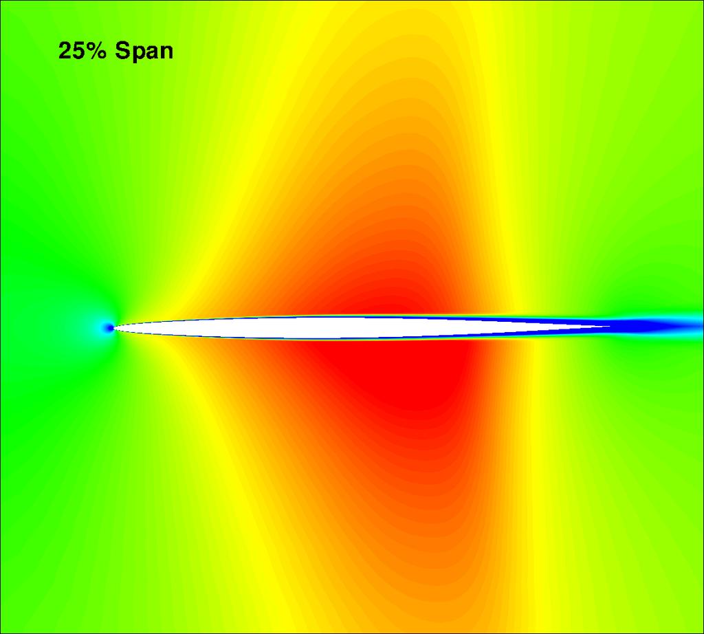
20 Figure 15: Instantaneous isentropic Mach number contours on suction surface. Left: M = 1.7; Right:M = M_is % Span T1=.3187 s T=.3371 s T3=.3734 s M_is % Span T1=.3187 s T=.3371 s T3=.3734 s M_is % Span T1=.3187 s T=.3371 s T3=.3734 s x/l x/l x/l Figure 16: Isentropic Mach number profile for M = 1.7


21 T1=.3451 s T=.3615 s T3=.381 s Figure 17: Mach number contours for M =.96 1
22 References [1] E. H. Dowell, and K. C. Hall, MODELING OF FLUID-STRUCTURE INTERACTION, Annual Review of Fluid Mechanics, vol. 33, pp , 1. [] O. Bendiksen and K. Kousen, Transonic Flutter Analysis Using the Euler Equations. AIAA Paper , [3] J. Rausch, R.D. Batina and T. Yang, Three-dimensional time-marching aeroelastic analyses using an unstructured-grid euler method, AIAA Journal, vol. 33, pp , [4] B. B. Prananta, H. M. H. L., and Z. R. J., Two-Dimensional Transonic Aeroelastic Analysis Using Thin-Layer Navier-Stokes Method, Journal of Fluid and Structures, vol. 1, pp , [5] E. Lee-Rausch and J. Batina, Calculation of AGARD Wing Flutter Using Navier-Stokes Aerodynamics. AIAA Paper , [6] K. Isogai, Transonic Dip Mechanism of Flutter of a Sweptback Wing: Part II, AIAA Journal, vol. 19, pp , September [7] Knight, D., Yan, H., Panaras, A. G., Zheltovodov, A., Advances in CFD Prediction of Shock Wave Turbulent Boundary Layer Interactions, Progress in Aerospace Sciences, vol. 39, pp , 3. [8] Sinha, K., Mahesh, K., Candler, G., Modeling the Effect of Shock Unsteadiness in Shock/Turbulent Boundary-Layer Interactions, AIAA Journal, vol. 43, pp , 5. [9] Morgan, B., Kawai, S., Lele, S. K., Large-Eddy Simulation of an Oblique Shock Impinging on a Turbulent Boundary Layer. AIAA Paper , 4th Fluid Dynamics Conference and Exhibit, June 8 - July 1, Chicago, Illinois, 1. [1] S. Priebe, M. Martin, Direct Numerical Simulation of Shockwave and Turbulent Boundary Layer Interactions. AIAA-9-589, 47th AIAA Aerospace Sciences Meeting, January 5-8, Orlando, FL, USA, 9. [11] P.R. Spalart, S. Deck, M. Shur, and K.D. Squires, A New Version of Detached-Eddy Simulation, Resistant to Ambiguous Grid Densities, Theoritical and Computational Fluid Dynamics, vol., pp , 6. [1] X.Y. Chen, B.Y. Wang, and G.C. Zha, Delayed Detached Eddy Simulation of 3-D Wing Flutter with Fully Coupled Fluid-Structural Interaction. AIAA Paper 1-53, 48th AIAA Aerospace Sciences Meeting Including the New Horizons Forum and Aerospace Exposition, Jan. 4-7, 1. [13] X.Y. Chen, and G.-C. Zha, Fully Coupled Fluid-Structural Interactions Using an Efficient High Solution Upwind Scheme, Journal of Fluid and Structure, vol., pp , 5. [14] X.-Y. Chen, G.-C. Zha, and M.-T. Yang, Numerical Simulation of 3-D Wing Flutter with Fully Coupled Fluid-Structural Interaction, Journal of Computers and Fluids, vol. 35, pp , 7. [15] Im, H.-S. and Zha, G.-C., Prediction of a Supersonic Wing Flutter Boundary Using a High Fidelity Detached Eddy Simulation. AIAA Paper 1-39, 5th AIAA Aerospace Sciences Meeting, Jan. 9-1., Nashville, TN, USA, 1. [16] P.R. Spalart, and S.R. Allmaras, A One-equation Turbulence Model for Aerodynamic Flows. AIAA , 199.
23 [17] P.R. Spalart, W.H. Jou, M. Strelets, and S.R. Allmaras, Comments on the Feasibility of LES for Wings, and on a Hybrid RANS/LES Approach. Advances in DNS/LES, 1st AFOSR Int. Conf. on DNS/LES, Greyden Press, Columbus, H., Aug. 4-8, [18] G.C. Zha, Y.Q. Shen, and B.Y. Wang, An improved low diffusion E-CUSP upwind scheme, Journal of Computer and Fluids, to appear 11. [19] G.C. Zha, Y.Q. Shen, and B.Y. Wang, Calculation of Transonic Flows Using WENO Method with a Low Diffusion E-CUSP Upwind Scheme. AIAA Paper 8-745, 46th AIAA Aerospace Sciences Meeting, Reno, NV, Jan. 8. [] P. Roe, Approximate Riemann Solvers, Parameter Vectors, and Difference Schemes, Journal of Computational Physics, vol. 43, pp , [1] J. Edwards, A Low-Diffusion Flux-Splitting Scheme for Navier-Stokes Calculations, Computer & Fluids, vol. 6, pp , [] B.Y. Wang, and G.C. Zha, Comparison of a Low Diffusion E-CUSP and the Roe Scheme for RANS Calculation. AIAA Paper 8-596, 46th AIAA Aerospace Sciences Meeting and Exhibit, Jan. 7-1, 8. [3] Shen, Y.Q., and Zha, G.C., Improvement of the WENO Scheme Smoothness Estimator, International Journal for Numerical Methods in Fluids, vol. 64,, pp , DOI:1.1/fld.186, 9. [4] Shen, Y.Q., Zha, G.C., and Wang, B.Y., Improvement of Stability and Accuracy of Implicit WENO Scheme, AIAA Journal, vol. 47, pp , DOI:1.514/ , 9. [5] Y.Q. Shen, B.Y. Wang, and G.C. Zha, Implicit WENO Scheme and High Order Viscous Formulas for Compressible Flows. AIAA Paper , 7. [6] A. Jameson, Time Dependent Calculations Using Multigrid with Applications to Unsteady Flows Past Airfoils and Wings. AIAA Paper , [7] E.C. Yates Jr., AGARD standard aeroelastic configurations for dynamic response. Candidate configuration I.-wing NASA-TM-149, [8] R.V. Goggett, R.V. Rainey, and H.G. Morgan, An experimental investigsation of Aerodynamic Effects of Airfoil Thickness on Transonic Flutter Characteristics. NASA TMX-79, [9] F. Liu, J. Cai, and Y. Zhu, Calculation of Wing flutter by a Coupled CFD-CSD method. AIAA- -97,. [3] M.A. Bakhle, T.S.R. Reddy, and T.G. Keith Jr., Time Domain Flutter Analysis of Cascades Using a Full-Potnetial Solver, AIAA Journal, vol. 3, pp ,
Investigation of Co-Flow Jet Airfoil Mixing Mechanism Using Large Eddy Simulation
 4st AIAA Fluid Dynamics Conference and Exhibit 27-3 June 2, Honolulu, Hawaii AIAA 2-398 Investigation of Co-Flow Jet Airfoil Mixing Mechanism Using Large Eddy Simulation Hong-Sik IM, Ge-Cheng Zha, Bertrand
Parallel Computation of Forced Vibration for A Compressor Cascade
 44th AIAA Aerospace Sciences Meeting and Exhibit 9-2 January 26, Reno, Nevada AIAA 26-628 AIAA Paper 26-628 Parallel Computation of Forced Vibration for A Compressor Cascade Zongjun Hu and Gecheng Zha
compression corner flows with high deflection angle, for example, the method cannot predict the location
 4nd AIAA Aerospace Sciences Meeting and Exhibit 5-8 January 4, Reno, Nevada Modeling the effect of shock unsteadiness in shock-wave/ turbulent boundary layer interactions AIAA 4-9 Krishnendu Sinha*, Krishnan
41st Aerospace Sciences Meeting and Exhibit 6-9 January 2003, Reno, Nevada Modeling shock unsteadiness in shock/turbulence interaction
 4st Aerospace Sciences Meeting and Exhibit 6-9 January 003, Reno, Nevada Modeling shock unsteadiness in shock/turbulence interaction AIAA 003-65 Krishnendu Sinha*, Krishnan Mahesh and Graham V. Candler
A HARMONIC BALANCE APPROACH FOR MODELING THREE-DIMENSIONAL NONLINEAR UNSTEADY AERODYNAMICS AND AEROELASTICITY
 ' - ' Proceedings of ASME International Mechanical Engineering Conference and Exposition November 17-22, 22, New Orleans, Louisiana, USA IMECE-22-3232 A HARMONIC ALANCE APPROACH FOR MODELING THREE-DIMENSIONAL
Available online at ScienceDirect. Procedia Engineering 79 (2014 ) 49 54
 49 54") Available online at www.sciencedirect.com ScienceDirect Procedia Engineering 79 (2014 ) 49 54 37th National Conference on Theoretical and Applied Mechanics (37th NCTAM 2013) & The 1st International Conference
Available online at www.sciencedirect.com ScienceDirect Procedia Engineering 79 (2014 ) 49 54 37th National Conference on Theoretical and Applied Mechanics (37th NCTAM 2013) & The 1st International Conference
Investigation of Non-synchronous Vibration Mechanism for a High Speed Axial Compressor Using Delayed DES
 AIAA SciTech 13-17 January 2014, National Harbor, Maryland 52nd Aerospace Sciences Meeting AIAA 2014-0789 Investigation of Non-synchronous Vibration Mechanism for a High Speed Axial Compressor Using Delayed
COMPUTATION OF CASCADE FLUTTER WITH A COUPLED AERODYNAMIC AND STRUCTURAL MODEL
 COMPUTATION OF CASCADE FLUTTER WITH A COUPLED AERODYNAMIC AND STRUCTURAL MODEL M. SADEGHI AND F. LIU Department of Mechanical and Aerospace Engineering University of California, Irvine, CA 92697-3975,
41st AIAA Aerospace Sciences Meeting and Exhibit January 6 9, 2003/Reno, NV
 AIAA 3 267 Calculation of Unsteady Transonic Flow by an Euler Method with Small Perturbation Boundary Conditions C. Gao, S. Luo, F. Liu Department of Mechanical and Aerospace Engineering University of
Simulation of Aeroelastic System with Aerodynamic Nonlinearity
 Simulation of Aeroelastic System with Aerodynamic Nonlinearity Muhamad Khairil Hafizi Mohd Zorkipli School of Aerospace Engineering, Universiti Sains Malaysia, Penang, MALAYSIA Norizham Abdul Razak School
COMPUTATIONAL STUDY OF SEPARATION CONTROL MECHANISM WITH THE IMAGINARY BODY FORCE ADDED TO THE FLOWS OVER AN AIRFOIL
 COMPUTATIONAL STUDY OF SEPARATION CONTROL MECHANISM WITH THE IMAGINARY BODY FORCE ADDED TO THE FLOWS OVER AN AIRFOIL Kengo Asada 1 and Kozo Fujii 2 ABSTRACT The effects of body force distribution on the
Limit Cycle Oscillations of a Typical Airfoil in Transonic Flow
 Limit Cycle Oscillations of a Typical Airfoil in Transonic Flow Denis B. Kholodar, United States Air Force Academy, Colorado Springs, CO 88 Earl H. Dowell, Jeffrey P. Thomas, and Kenneth C. Hall Duke University,
Improved Seventh-Order WENO Scheme
 48th AIAA Aerospace Sciences Meeting Including the New Horizons Forum and Aerospace Eposition 4-7 January 2, Orlando, Florida AIAA 2-45 Improved Seventh-Order WENO Scheme Yiqing Shen Gecheng Zha Dept.
Mixing-Plane Method for Flutter Computation in Multi-stage Turbomachines
 47th AIAA Aerospace Sciences Meeting Including The New Horizons Forum and Aerospace Exposition 5-8 January 2009, Orlando, Florida AIAA 2009-862 Mixing-Plane Method for Flutter Computation in Multi-stage
LES Study of Shock Wave and Turbulent Boundary Layer Interaction
 51st AIAA Aerospace Sciences Meeting including the New Horizons Forum and Aerospace Exposition 07-10 January 2013, Grapevine (Dallas/Ft. Worth Region), Texas AIAA 2013-0984 LES Study of Shock Wave and
Aeroelastic Analysis of Engine Nacelle Strake Considering Geometric Nonlinear Behavior
 Aeroelastic Analysis of Engine Nacelle Strake Considering Geometric Nonlinear Behavior N. Manoj Abstract The aeroelastic behavior of engine nacelle strake when subjected to unsteady aerodynamic flows is
Large-eddy simulations for wind turbine blade: rotational augmentation and dynamic stall
 Large-eddy simulations for wind turbine blade: rotational augmentation and dynamic stall Y. Kim, I.P. Castro, and Z.T. Xie Introduction Wind turbines operate in the atmospheric boundary layer and their
Computation of NACA0012 Airfoil Transonic Buffet Phenomenon with Unsteady Navier-Stokes Equations
 5th AIAA Aerospace Sciences Meeting including the New Horizons Forum and Aerospace Exposition 9-2 January 22, Nashville, Tennessee AIAA 22-699 Computation of NACA2 Airfoil Transonic Buffet Phenomenon with
Investigations of Double Surface Co-Flow Jet Transonic Airfoil
 University of Miami Scholarly Repository Open Access Theses Electronic Theses and Dissertations 2019-02-09 Investigations of Double Surface Co-Flow Jet Transonic Airfoil Luchen Wang University of Miami,
Analysis of Shock Motion in STBLI Induced by a Compression Ramp Configuration Using DNS Data
 45th AIAA Aerospace Science Meeting and Exhibit, January 8 11, 25/Reno, Nevada Analysis of Shock Motion in STBLI Induced by a Compression Ramp Configuration Using DNS Data M. Wu and M.P. Martin Mechanical
New DNS Results of Shockwave/Turbulent Boundary Layer Interaction
 36th AIAA Fluid Dynamics Conference, June 5 8, 26/San Francisco,California New DNS Results of Shockwave/Turbulent Boundary Layer Interaction M. Wu and M.P. Martin Mechanical and Aerospace Engineering Department
Application of Dual Time Stepping to Fully Implicit Runge Kutta Schemes for Unsteady Flow Calculations
 Application of Dual Time Stepping to Fully Implicit Runge Kutta Schemes for Unsteady Flow Calculations Antony Jameson Department of Aeronautics and Astronautics, Stanford University, Stanford, CA, 94305
Application of a Non-Linear Frequency Domain Solver to the Euler and Navier-Stokes Equations
 Application of a Non-Linear Frequency Domain Solver to the Euler and Navier-Stokes Equations Matthew McMullen and Antony Jameson and Juan J. Alonso Dept. of Aeronautics & Astronautics Stanford University
A Multi-Dimensional Limiter for Hybrid Grid
 APCOM & ISCM 11-14 th December, 2013, Singapore A Multi-Dimensional Limiter for Hybrid Grid * H. W. Zheng ¹ 1 State Key Laboratory of High Temperature Gas Dynamics, Institute of Mechanics, Chinese Academy
Nonlinear Aeroelastic Analysis of a Wing with Control Surface Freeplay
 Copyright c 7 ICCES ICCES, vol., no.3, pp.75-8, 7 Nonlinear Aeroelastic Analysis of a with Control Surface Freeplay K.S. Kim 1,J.H.Yoo,J.S.Bae 3 and I. Lee 1 Summary In this paper, nonlinear aeroelastic
Hybrid RANS/LES simulations of a cavitating flow in Venturi
 Hybrid RANS/LES simulations of a cavitating flow in Venturi TSFP-8, 28-31 August 2013 - Poitiers - France Jean Decaix jean.decaix@hevs.ch University of Applied Sciences, Western Switzerland Eric Goncalves
Transonic Flutter Prediction of Supersonic Jet Trainer with Various External Store Configurations
 Transonic Flutter Prediction of Supersonic Jet Trainer with Various External Store Configurations In Lee * Korea Advanced Institute of Science and Technology, Daejeon, 305-701, Korea Hyuk-Jun Kwon Agency
Numerical Investigation of the Transonic Base Flow of A Generic Rocket Configuration
 1 Numerical Investigation of the Transonic Base Flow of A Generic Rocket Configuration A. Henze, C. Glatzer, M. Meinke, W. Schröder Institute of Aerodynamics, RWTH Aachen University, Germany March 21,
APPLICATION OF HYBRID CFD/CAA TECHNIQUE FOR MODELING PRESSURE FLUCTUATIONS IN TRANSONIC FLOWS
 TASK QUARTERLY Vol. 17, Nos 3 4, 2013, pp. 145 154 APPLICATION OF HYBRID CFD/CAA TECHNIQUE FOR MODELING PRESSURE FLUCTUATIONS IN TRANSONIC FLOWS SŁAWOMIR DYKAS, WŁODZIMIERZ WRÓBLEWSKI AND SEBASTIAN RULIK
GT UNSTEADY SIMULATION OF A TWO-STAGE COOLED HIGH PRESSURE TURBINE USING AN EFFICIENT NON-LINEAR HARMONIC BALANCE METHOD
 Proceedings of ASME Turbo Expo 213: Turbine Technical Conference and Exposition GT213 June 3-7, 213, San Antonio, Texas, USA GT213-94574 UNSTEADY SIMULATION OF A TWO-STAGE COOLED HIGH PRESSURE TURBINE
Numerical investigation of the flow instabilities in centrifugal fan
 Proceedings of the 4th WSEAS International Conference on Fluid Mechanics and Aerodynamics, Elounda, Greece, August 21-23, 26 (pp282-288) Numerical investigation of the flow instabilities in centrifugal
DETACHED-EDDY SIMULATION OF FLOW PAST A BACKWARD-FACING STEP WITH A HARMONIC ACTUATION
 DETACHED-EDDY SIMULATION OF FLOW PAST A BACKWARD-FACING STEP WITH A HARMONIC ACTUATION Liang Wang*, Ruyun Hu*, Liying Li*, Song Fu* *School of Aerospace Engineering, Tsinghua University, Beijing 100084,
Elliptic Trailing Edge for a High Subsonic Turbine Cascade
 Elliptic Trailing Edge for a High Subsonic Turbine Cascade Mahmoud M. El-Gendi 1, Mohammed K. Ibrahim 2, Koichi Mori 3, and Yoshiaki Nakamura 4 1 Graduate School of Engineering, Nagoya University, Nagoya
Numerical Methods in Aerodynamics. Turbulence Modeling. Lecture 5: Turbulence modeling
 Turbulence Modeling Niels N. Sørensen Professor MSO, Ph.D. Department of Civil Engineering, Alborg University & Wind Energy Department, Risø National Laboratory Technical University of Denmark 1 Outline
INVESTIGATION OF THE FLOW OVER AN OSCILLATING CYLINDER WITH THE VERY LARGE EDDY SIMULATION MODEL
 ECCOMAS Congress 2016 VII European Congress on Computational Methods in Applied Sciences and Engineering M. Papadrakakis, V. Papadopoulos, G. Stefanou, V. Plevris (eds.) Crete Island, Greece, 5 10 June
Aerodynamic force analysis in high Reynolds number flows by Lamb vector integration
 Aerodynamic force analysis in high Reynolds number flows by Lamb vector integration Claudio Marongiu, Renato Tognaccini 2 CIRA, Italian Center for Aerospace Research, Capua (CE), Italy E-mail: c.marongiu@cira.it
Reduced order model of three-dimensional Euler equations using proper orthogonal decomposition basis
 Journal of Mechanical Science and Technology 24 (2) (2010) 601~608 www.springerlink.com/content/1738-494x DOI 10.1007/s12206-010-0106-0 Reduced order model of three-dimensional Euler equations using proper
Zonal hybrid RANS-LES modeling using a Low-Reynolds-Number k ω approach
 Zonal hybrid RANS-LES modeling using a Low-Reynolds-Number k ω approach S. Arvidson 1,2, L. Davidson 1, S.-H. Peng 1,3 1 Chalmers University of Technology 2 SAAB AB, Aeronautics 3 FOI, Swedish Defence
AA214B: NUMERICAL METHODS FOR COMPRESSIBLE FLOWS
 AA214B: NUMERICAL METHODS FOR COMPRESSIBLE FLOWS 1 / 29 AA214B: NUMERICAL METHODS FOR COMPRESSIBLE FLOWS Hierarchy of Mathematical Models 1 / 29 AA214B: NUMERICAL METHODS FOR COMPRESSIBLE FLOWS 2 / 29
MULTIGRID CALCULATIONS FOB. CASCADES. Antony Jameson and Feng Liu Princeton University, Princeton, NJ 08544
 MULTIGRID CALCULATIONS FOB. CASCADES Antony Jameson and Feng Liu Princeton University, Princeton, NJ 0544 1. Introduction Development of numerical methods for internal flows such as the flow in gas turbines
Aeroelasticity. Lecture 9: Supersonic Aeroelasticity. G. Dimitriadis. AERO0032-1, Aeroelasticity and Experimental Aerodynamics, Lecture 9
 Aeroelasticity Lecture 9: Supersonic Aeroelasticity G. Dimitriadis AERO0032-1, Aeroelasticity and Experimental Aerodynamics, Lecture 9 1 Introduction All the material presented up to now concerned incompressible
Active Flutter Control using an Adjoint Method
 44th AIAA Aerospace Sciences Meeting and Exhibit 9-12 January 26, Reno, Nevada AIAA 26-844 44th AIAA Aerospace Sciences Meeting and Exhibit, Reno, Nevada, 9 12 Jan, 26. Active Flutter Control using an
WALL ROUGHNESS EFFECTS ON SHOCK BOUNDARY LAYER INTERACTION FLOWS
 ISSN (Online) : 2319-8753 ISSN (Print) : 2347-6710 International Journal of Innovative Research in Science, Engineering and Technology An ISO 3297: 2007 Certified Organization, Volume 2, Special Issue
RANS Solutions Using High Order Discontinuous Galerkin Methods
 RANS Solutions Using High Order Discontinuous Galerkin Methods Ngoc Cuong Nguyen, Per-Olof Persson and Jaime Peraire Massachusetts Institute of Technology, Cambridge, MA 2139, U.S.A. We present a practical
COMPUTATIONAL SIMULATION OF THE FLOW PAST AN AIRFOIL FOR AN UNMANNED AERIAL VEHICLE
 COMPUTATIONAL SIMULATION OF THE FLOW PAST AN AIRFOIL FOR AN UNMANNED AERIAL VEHICLE L. Velázquez-Araque 1 and J. Nožička 2 1 Division of Thermal fluids, Department of Mechanical Engineering, National University
STUDY OF THREE-DIMENSIONAL SYNTHETIC JET FLOWFIELDS USING DIRECT NUMERICAL SIMULATION.
 42 nd AIAA Aerospace Sciences Meeting and Exhibit 5-8 January 2004/Reno, NV STUDY OF THREE-DIMENSIONAL SYNTHETIC JET FLOWFIELDS USING DIRECT NUMERICAL SIMULATION. B.R.Ravi * and R. Mittal, Department of
Implementing a Partitioned Algorithm for Fluid-Structure Interaction of Flexible Flapping Wings within Overture
 10 th Symposimum on Overset Composite Grids and Solution Technology, NASA Ames Research Center Moffett Field, California, USA 1 Implementing a Partitioned Algorithm for Fluid-Structure Interaction of Flexible
AN UNCERTAINTY ESTIMATION EXAMPLE FOR BACKWARD FACING STEP CFD SIMULATION. Abstract
 nd Workshop on CFD Uncertainty Analysis - Lisbon, 19th and 0th October 006 AN UNCERTAINTY ESTIMATION EXAMPLE FOR BACKWARD FACING STEP CFD SIMULATION Alfredo Iranzo 1, Jesús Valle, Ignacio Trejo 3, Jerónimo
Explicit algebraic Reynolds stress models for internal flows
 5. Double Circular Arc (DCA) cascade blade flow, problem statement The second test case deals with a DCA compressor cascade, which is considered a severe challenge for the CFD codes, due to the presence
Stabilization of Explicit Flow Solvers Using a Proper Orthogonal Decomposition Technique
 50th AIAA Aerospace Sciences Meeting including the New Horizons Forum and Aerospace Exposition 09-12 January 2012, Nashville, Tennessee AIAA 2012-1096 Stabilization of Explicit Flow Solvers Using a Proper
Numerical Researches on Aeroelastic Problem of a Rotor due to IGV/Fan Interaction
 47th AIAA Aerospace Sciences Meeting Including The New Horizons Forum and Aerospace Exposition 5-8 January 9, Orlando, Florida AIAA 9-865 Numerical Researches on Aeroelastic Problem of a Rotor due to IGV/Fan
DYNAMIC RESPONSE OF AN AIRPLANE ELASTIC STRUCTURE IN TRANSONIC FLOW
 DYNAMIC RESPONSE OF AN AIRPLANE ELASTIC STRUCTURE IN TRANSONIC FLOW S. Kuzmina*, F. Ishmuratov*, O. Karas*, A.Chizhov* * Central Aerohydrodynamic Institute (TsAGI), Zhukovsky, Russia Keywords: aeroelasticity,
Turbulent Boundary Layers & Turbulence Models. Lecture 09
 Turbulent Boundary Layers & Turbulence Models Lecture 09 The turbulent boundary layer In turbulent flow, the boundary layer is defined as the thin region on the surface of a body in which viscous effects
Non-Synchronous Vibrations of Turbomachinery Airfoils
 Non-Synchronous Vibrations of Turbomachinery Airfoils 600 500 NSV Frequency,!, hz 400 300 200 F.R. Flutter 100 SFV 0 0 1000 2000 3000 4000 5000 6000 7000 8000 9000 10000 Rotor Speed,!, RPM Kenneth C. Hall,
Masters in Mechanical Engineering. Problems of incompressible viscous flow. 2µ dx y(y h)+ U h y 0 < y < h,
+ U h y 0 < y < h,") Masters in Mechanical Engineering Problems of incompressible viscous flow 1. Consider the laminar Couette flow between two infinite flat plates (lower plate (y = 0) with no velocity and top plate (y =
Masters in Mechanical Engineering Problems of incompressible viscous flow 1. Consider the laminar Couette flow between two infinite flat plates (lower plate (y = 0) with no velocity and top plate (y =
Physical Diffusion Cures the Carbuncle Phenomenon
 Physical Diffusion Cures the Carbuncle Phenomenon J. M. Powers 1, J. Bruns 1, A. Jemcov 1 1 Department of Aerospace and Mechanical Engineering University of Notre Dame, USA Fifty-Third AIAA Aerospace Sciences
High Speed Aerodynamics. Copyright 2009 Narayanan Komerath
 Welcome to High Speed Aerodynamics 1 Lift, drag and pitching moment? Linearized Potential Flow Transformations Compressible Boundary Layer WHAT IS HIGH SPEED AERODYNAMICS? Airfoil section? Thin airfoil
A physically consistent and numerically robust k-ɛ model for computing turbulent flows with shock waves
 A physically consistent and numerically robust k-ɛ model for computing turbulent flows with shock waves Pratikkumar Raje, Krishnendu Sinha Indian Institute of Technology Bombay, Mumbai, 400076, India Abstract
Modeling Unsteady Flow in Turbomachinery Using a Harmonic Balance Technique
 Modeling Unsteady Flow in Turbomachinery Using a Harmonic Balance Technique Torsten Palenschat 317220 30.04.2014 Master seminar CES WS 2013/2014 Center for Computational Engineering Sciences RWTH Aachen
Zonal modelling approach in aerodynamic simulation
 Zonal modelling approach in aerodynamic simulation and Carlos Castro Barcelona Supercomputing Center Technical University of Madrid Outline 1 2 State of the art Proposed strategy 3 Consistency Stability
Direct Numerical Simulations of Plunging Airfoils
 48th AIAA Aerospace Sciences Meeting Including the New Horizons Forum and Aerospace Exposition 4-7 January 010, Orlando, Florida AIAA 010-78 Direct Numerical Simulations of Plunging Airfoils Yves Allaneau
Is My CFD Mesh Adequate? A Quantitative Answer
 Is My CFD Mesh Adequate? A Quantitative Answer Krzysztof J. Fidkowski Gas Dynamics Research Colloqium Aerospace Engineering Department University of Michigan January 26, 2011 K.J. Fidkowski (UM) GDRC 2011
Shock/boundary layer interactions
 Shock/boundary layer interactions Turbulent compressible channel flows F.S. Godeferd Laboratoire de Mécanique des Fluides et d Acoustique Ecole Centrale de Lyon, France Journée Calcul Intensif en Rhône
Numerical Study of Natural Unsteadiness Using Wall-Distance-Free Turbulence Models
 Numerical Study of Natural Unsteadiness Using Wall-Distance-Free urbulence Models Yi-Lung Yang* and Gwo-Lung Wang Department of Mechanical Engineering, Chung Hua University No. 707, Sec 2, Wufu Road, Hsin
URANS Computations of Cavitating Flow around a 2-D Wedge by Compressible Two-Phase Flow Solver
 URANS Computations of Cavitating Flow around a 2-D Wedge by Compressible Two-Phase Flow Solver *Yohan Choe 1), Hyeongjun Kim 1), Chongam Kim 2) 1), 2) Department of Aerospace Engineering, Seoul National
NUMERICAL SIMULATION AND MODELING OF UNSTEADY FLOW AROUND AN AIRFOIL. (AERODYNAMIC FORM)
") Journal of Fundamental and Applied Sciences ISSN 1112-9867 Available online at http://www.jfas.info NUMERICAL SIMULATION AND MODELING OF UNSTEADY FLOW AROUND AN AIRFOIL. (AERODYNAMIC FORM) M. Y. Habib
Journal of Fundamental and Applied Sciences ISSN 1112-9867 Available online at http://www.jfas.info NUMERICAL SIMULATION AND MODELING OF UNSTEADY FLOW AROUND AN AIRFOIL. (AERODYNAMIC FORM) M. Y. Habib
Effect of Applied Magnetic Field on Shock Boundary Layer Interaction
 University of Kentucky UKnowledge Mechanical Engineering Faculty Publications Mechanical Engineering 1-2012 Effect of Applied Magnetic Field on Shock Boundary Layer Interaction Ovais U. Khan University
FREQUENCY DOMAIN FLUTTER ANALYSIS OF AIRCRAFT WING IN SUBSONIC FLOW
 FREQUENCY DOMAIN FLUTTER ANALYSIS OF AIRCRAFT WING IN SUBSONIC FLOW Ms.K.Niranjana 1, Mr.A.Daniel Antony 2 1 UG Student, Department of Aerospace Engineering, Karunya University, (India) 2 Assistant professor,
Coupled Fluid and Heat Flow Analysis Around NACA Aerofoil Profiles at Various Mach Numbers
 International Journal of Engineering Research and Technology. ISSN 0974-3154 Volume 6, Number 2 (2013), pp. 249-258 International Research Publication House http://www.irphouse.com Coupled Fluid and Heat
APPLICATION OF SPACE-TIME MAPPING ANALYSIS METHOD TO UNSTEADY NONLINEAR GUST-AIRFOIL INTERACTION PROBLEM
 AIAA 2003-3693 APPLICATION OF SPACE-TIME MAPPING ANALYSIS METHOD TO UNSTEADY NONLINEAR GUST-AIRFOIL INTERACTION PROBLEM Vladimir V. Golubev* and Axel Rohde Embry-Riddle Aeronautical University Daytona
Aalto University School of Science and Technology CFD-group/ Department of Applied Mechanics. MEMO No CFD/MECHA DATE: March 15, 2012
 Aalto University School of Science and Technology CFD-group/ Department of Applied Mechanics MEMO No CFD/MECHA-2-212 DATE: March 15, 212 TITLE The Effect of Free-Stream Turbulence Parameters on the SST
Aeroelastic Gust Response
 Aeroelastic Gust Response Civil Transport Aircraft - xxx Presented By: Fausto Gill Di Vincenzo 04-06-2012 What is Aeroelasticity? Aeroelasticity studies the effect of aerodynamic loads on flexible structures,
EFFECT OF REYNOLDS NUMBER ON THE UNSTEADY FLOW AND ACOUSTIC FIELDS OF SUPERSONIC CAVITY
 Proceedings of FEDSM 03 4TH ASME_JSME Joint Fluids Engineering Conference Honolulu, Hawaii, USA, July 6 11, 2003 FEDSM2003-45473 EFFECT OF REYNOLDS NUMBER ON THE UNSTEADY FLOW AND ACOUSTIC FIELDS OF SUPERSONIC
EFFECTS OF ROTOR TIP CLEARANCE ON TIP CLEARANCE FLOW POTENTIALLY LEADING TO NSV IN AN AXIAL COMPRESSOR
 roceedings of ASME Turbo Expo, June -5,, Copenhagen, Denmark GT-6848 EFFECTS OF ROTOR TI CLEARANCE ON TI CLEARANCE FLOW OTENTIALLY LEADING TO NSV IN AN AXIAL COMRESSOR Hong-Sik Im Ge-Cheng Zha Dept. of
A Computational Investigation of a Turbulent Flow Over a Backward Facing Step with OpenFOAM
 206 9th International Conference on Developments in esystems Engineering A Computational Investigation of a Turbulent Flow Over a Backward Facing Step with OpenFOAM Hayder Al-Jelawy, Stefan Kaczmarczyk
Aerodynamic Resonance in Transonic Airfoil Flow. J. Nitzsche, R. H. M. Giepman. Institute of Aeroelasticity, German Aerospace Center (DLR), Göttingen
, Göttingen") Aerodynamic Resonance in Transonic Airfoil Flow J. Nitzsche, R. H. M. Giepman Institute of Aeroelasticity, German Aerospace Center (DLR), Göttingen Source: A. Šoda, PhD thesis, 2006 Slide 2/39 Introduction
Aerodynamic Resonance in Transonic Airfoil Flow J. Nitzsche, R. H. M. Giepman Institute of Aeroelasticity, German Aerospace Center (DLR), Göttingen Source: A. Šoda, PhD thesis, 2006 Slide 2/39 Introduction
[N175] Development of Combined CAA-CFD Algorithm for the Efficient Simulation of Aerodynamic Noise Generation and Propagation
![[N175] Development of Combined CAA-CFD Algorithm for the Efficient Simulation of Aerodynamic Noise Generation and Propagation](/thumbs/95/123895144.jpg "[N175] Development of Combined CAA-CFD Algorithm for the Efficient Simulation of Aerodynamic Noise Generation and Propagation") The 32nd International Congress and Exposition on Noise Control Engineering Jeju International Convention Center, Seogwipo, Korea, August 25-28, 2003 [N175] Development of Combined CAA-CFD Algorithm for
The 32nd International Congress and Exposition on Noise Control Engineering Jeju International Convention Center, Seogwipo, Korea, August 25-28, 2003 [N175] Development of Combined CAA-CFD Algorithm for
Manhar Dhanak Florida Atlantic University Graduate Student: Zaqie Reza
 REPRESENTING PRESENCE OF SUBSURFACE CURRENT TURBINES IN OCEAN MODELS Manhar Dhanak Florida Atlantic University Graduate Student: Zaqie Reza 1 Momentum Equations 2 Effect of inclusion of Coriolis force
In the continuing effort to better understand hypersonic flow phenomena, mixing characteristics of various
 50th AIAA Aerospace Sciences Meeting including the New Horizons Forum and Aerospace Exposition 09-12 January 2012, Nashville, Tennessee AIAA 2012-0480 Hybrid LES / RANS Simulations of Shock-Distorted Injection
SIMULATION OF THREE-DIMENSIONAL INCOMPRESSIBLE CAVITY FLOWS
 ICAS 2000 CONGRESS SIMULATION OF THREE-DIMENSIONAL INCOMPRESSIBLE CAVITY FLOWS H Yao, R K Cooper, and S Raghunathan School of Aeronautical Engineering The Queen s University of Belfast, Belfast BT7 1NN,
Some effects of large blade deflections on aeroelastic stability
 47th AIAA Aerospace Sciences Meeting Including The New Horizons Forum and Aerospace Exposition 5-8 January 29, Orlando, Florida AIAA 29-839 Some effects of large blade deflections on aeroelastic stability
Application of High-Order Summation-by-Parts Operators to the Steady Reynolds-Averaged Navier-Stokes Equations. Xiaoyue Shen
 Application of High-Order Summation-by-Parts Operators to the Steady Reynolds-Averaged Navier-Stokes Equations Xiaoyue Shen Supervisor: Prof. David W. Zingg A thesis submitted in conformity with the requirements
A Non-Intrusive Polynomial Chaos Method For Uncertainty Propagation in CFD Simulations
 An Extended Abstract submitted for the 44th AIAA Aerospace Sciences Meeting and Exhibit, Reno, Nevada January 26 Preferred Session Topic: Uncertainty quantification and stochastic methods for CFD A Non-Intrusive
THE ANALYSIS OF LAMINATE LAY-UP EFFECT ON THE FLUTTER SPEED OF COMPOSITE STABILIZERS
 THE ANALYSIS OF LAMINATE LAY-UP EFFECT ON THE FLUTTER SPEED OF COMPOSITE STABILIZERS Mirko DINULOVIĆ*, Boško RAŠUO* and Branimir KRSTIĆ** * University of Belgrade, Faculty of Mechanical Engineering, **
RANS Equations in Curvilinear Coordinates
 Appendix C RANS Equations in Curvilinear Coordinates To begin with, the Reynolds-averaged Navier-Stokes RANS equations are presented in the familiar vector and Cartesian tensor forms. Each term in the
Using Automatic Differentiation to Create a Nonlinear Reduced Order Model Aeroelastic Solver
 Using Automatic Differentiation to Create a Nonlinear Reduced Order Model Aeroelastic Solver Jeffrey P. Thomas, Earl H. Dowell, and Kenneth C. Hall Duke University, Durham, NC 27708 0300 A novel nonlinear
CHAPTER 4 OPTIMIZATION OF COEFFICIENT OF LIFT, DRAG AND POWER - AN ITERATIVE APPROACH
 82 CHAPTER 4 OPTIMIZATION OF COEFFICIENT OF LIFT, DRAG AND POWER - AN ITERATIVE APPROACH The coefficient of lift, drag and power for wind turbine rotor is optimized using an iterative approach. The coefficient
The Computations of Jet Interaction on a Generic Supersonic Missile
 The Computations of Jet Interaction on a Generic Supersonic Missile *Jinbum Huh 1) and Seungsoo Lee 2) 1), 2) Department of Aerospace Engineering, Inha Univ., Incheon, Korea 2) slee@inha.ac.kr ABSTRACT
On the transient modelling of impinging jets heat transfer. A practical approach
 Turbulence, Heat and Mass Transfer 7 2012 Begell House, Inc. On the transient modelling of impinging jets heat transfer. A practical approach M. Bovo 1,2 and L. Davidson 1 1 Dept. of Applied Mechanics,
A combined application of the integral wall model and the rough wall rescaling-recycling method
 AIAA 25-299 A combined application of the integral wall model and the rough wall rescaling-recycling method X.I.A. Yang J. Sadique R. Mittal C. Meneveau Johns Hopkins University, Baltimore, MD, 228, USA
RANS-LES inlet boundary condition for aerodynamic and aero-acoustic. acoustic applications. Fabrice Mathey Davor Cokljat Fluent Inc.
 RANS-LES inlet boundary condition for aerodynamic and aero-acoustic acoustic applications Fabrice Mathey Davor Cokljat Fluent Inc. Presented by Fredrik Carlsson Fluent Sweden ZONAL MULTI-DOMAIN RANS/LES
A finite-volume algorithm for all speed flows
 A finite-volume algorithm for all speed flows F. Moukalled and M. Darwish American University of Beirut, Faculty of Engineering & Architecture, Mechanical Engineering Department, P.O.Box 11-0236, Beirut,
Computational Fluid Dynamics 2
 Seite 1 Introduction Computational Fluid Dynamics 11.07.2016 Computational Fluid Dynamics 2 Turbulence effects and Particle transport Martin Pietsch Computational Biomechanics Summer Term 2016 Seite 2
Turbomachinery Applications with the Time Spectral Method
 35th AIAA Fluid Dynamics Conference and Exhibit, June 6-9,005, Toronto,Ontario Turbomachinery Applications with the Time Spectral Method Edwin van der Weide, Arathi K Gopinath and Antony Jameson Stanford
Detached Eddy Simulation on Hypersonic Base Flow Structure of Reentry-F Vehicle
 Available online at www.sciencedirect.com ScienceDirect Procedia Engineering 00 (2014) 000 000 www.elsevier.com/locate/procedia APISAT2014, 2014 Asia-Pacific International Symposium on Aerospace Technology,
Fluid-Structure Interaction Problems using SU2 and External Finite-Element Solvers
 Fluid-Structure Interaction Problems using SU2 and External Finite-Element Solvers R. Sanchez 1, D. Thomas 2, R. Palacios 1, V. Terrapon 2 1 Department of Aeronautics, Imperial College London 2 Department
DIRECT NUMERICAL SIMULATIONS OF HIGH SPEED FLOW OVER CAVITY. Abstract
 3 rd AFOSR International Conference on DNS/LES (TAICDL), August 5-9 th, 2001, Arlington, Texas. DIRECT NUMERICAL SIMULATIONS OF HIGH SPEED FLOW OVER CAVITY A. HAMED, D. BASU, A. MOHAMED AND K. DAS Department
Numerical Analysis of Active Cascade Flutter Control with Smart Structure
 Proceedings of the International Gas Turbine Congress Tokyo November -7, IGTCTokyo TS-55 Numerical Analysis of Active Cascade Flutter Control with Smart Structure Junichi Kazawa and Toshinori Watanabe
The Simulation of Wraparound Fins Aerodynamic Characteristics
 The Simulation of Wraparound Fins Aerodynamic Characteristics Institute of Launch Dynamics Nanjing University of Science and Technology Nanjing Xiaolingwei 00 P. R. China laithabbass@yahoo.com Abstract:
Further Studies of Airfoils Supporting Non-unique Solutions in Transonic Flow
 29th AIAA Applied Aerodynamics Conference 27-30 June 2011, Honolulu, Hawaii AIAA 2011-3509 Further Studies of Airfoils Supporting Non-unique Solutions in Transonic Flow Antony Jameson, John C. Vassberg,