Introduction and Background
|
|
|
- Tamsyn Bradley
- 5 years ago
- Views:
Transcription
1 Analog CMOS Integrated Circuit Design Introduction and Background Dr. Jawdat Abu-Taha Department of Electrical and Computer Engineering Islamic University of Gaza 1
2 Marking Assignments 10% (4 to 6) Midterm 25% Project 20% Final Exam 45% 2
3 References Recommended Textbook: Behzad Razavi, Design of Analog CMOS Integrated Hill, 2001 Some other useful references: Circuits, McGraw- T. Chan Carusone, D. Johns and K. Martin, Analog Integrated Circuit Design, 2 nd Edition, John Wiley, 2011 P. Gray, P. Hurst, S. Lewis, and R. Meyer, Analysis and Design of Analog Integrated Circuits, Edition, John Wiley, 2009 SM 5 th D. Holberg and P. Allen, CMOS Analog Circuit Design, Oxford University Press, 2011 R. Jacob Baker, CMOS Circuit Design, Layout, and Simulation, Edition, Wiley-IEEE Press, 2010 A. Sedra and K.C. Smith, Microelectronic Circuits, Oxford University Press, 2004, 2009 Journal Circuits 3 rd 5 th or 6 th Edition, 3 rd Edition, and conference articles including IEEE Journal of Solid-State and International Solid-State Circuits Conference 3
4 Why Analog? Most of the physical signals are analog in nature! Although digital is great we need an analog interface to convert physical signals from analog to digital Also, in some application after processing the signals in digital we need to convert them back to analog. Thus in many applications analog and mixed-signal circuits performance bottlenecks. domain, are the Also with constant process improvements the boundary of between high-speed digital and analog circuits becomes more and more fuzzy! That is why analog and mixed-signal designers are still and hopefully will be in demand for the foreseeable future. SM 5
5 Data Converter Typical Real World System AFE DSP Example: G Filter ADC DSP SM 6

6 Intel 45 nm Process SM 8
7 Suggested Reading Structure of MOS Transistors Threshold Voltage Background 4. Long-Channel Current Equations 5. Regions of Operation 6. Transconductance 7. Second-Order Effects 8. Short-Channel Effects 9. MOS Layout 10.Device Capacitances 11.Small-signal Models 12.Circuit Impedance 13.Equivalent Transconductance SM EECE 488 Set 1: Introduction and Background 9
8 Suggested Reading Most of the material in this set are based on Chapters 2, 16, and 17 of the Razavi s CMOS Integrated Circuits book: Design of Analog Many of the figures in this set are from Design of Analog CMOS Integrated Circuits, McGraw-Hill, 2001, unless otherwise noted. SM 10
9 Transistor Transistor stands for Transistor are semiconductor devices that can be classified as Bipolar Junction Transistors (BJTs) Field Effect Transistors (FETs) Depletion-Mode FETs or (e.g., JFETs) Enhancement-Mode FETs (e.g., MOSFETs) 11
10 Simplistic Model MOS transistors have three terminals: Gate, Source, and Drain The voltage of the Gate terminal determines between Source and Drain (Short or Open). Thus, MOS devices behave like a switch the type of connection NMOS PMOS V G high V G low Device is ON D is shorted to S Device is OFF D & S are disconnected Device is OFF D & S are disconnected Device is ON D is shorted to S 12

 except that Source")
11 Physical Structure - 1 Source and Drain terminals are identical charge carriers, and Drain receives them. MOS devices have in fact 4 terminals: Source, Drain, Gate, Substrate (bulk) except that Source provides 13

12 Physical Structure - 2 Charge Carriers are electrons in NMOS devices, PMOS devices. Electrons have a higher mobility than holes So, NMOS devices are faster than PMOS devices We rather to have a p-type substrate?! and holes in L D : Due to Side Diffusion Poly-silicon used instead of Metal for fabrication reasons Actual length of the channel (L eff ) is less than the length of gate 14
 4 terminals: In order to have all PN junctions reverse-biased, substrate of NMOS is connected to the most")
13 Physical Structure - 3 N-wells allow both NMOS and PMOS devices to reside on the same piece of die. As mentioned, NMOS Source, Drain, Gate, and PMOS devices have Substrate (bulk) 4 terminals: In order to have all PN junctions reverse-biased, substrate of NMOS is connected to the most negative voltage, and substrate of PMOS is connected to the most positive voltage. 15
14 Physical Structure - 4 MOS transistor Symbols: In NMOS Devices: Source e lect ron Drain Current flows from Drain to Source In PMOS Devices: Source h ole Drain Current flows from Source to Drain Current flow determines which terminal is Source and which one is Drain. Equivalently, source and drain can be determined based on their relative voltages. 16
15 Threshold Voltage - 1 Consider an NMOS: as the gate voltage is increased, the surface under the gate is depleted. If the gate voltage increases more, free electrons appear under the gate and a conductive channel is formed. (a) An NMOS driven by a gate voltage, (b) formation of depletion region, (c) onset of inversion, and (d) channel formation As mentioned channel under before, in NMOS devices charge carriers in the the gate are electrons. 17
 Increasing induces an gate voltage above this threshold (denoted by V TH or V t ) inversion layer (conductive channel) under the")
16 Threshold Voltage - 2 Intuitively, the threshold voltage is the gate voltage that forces the interface (surface under the gate) to be completely depleted of charge (in NMOS the interface is as much n-type as the substrate is p-type) Increasing induces an gate voltage above this threshold (denoted by V TH or V t ) inversion layer (conductive channel) under the gate. 18
17 Threshold Voltage - 3 Analytically: V TH MS 2 F Q dep C ox Where: MS Built - inpotential gate Silicon the difference between the work functions of the polysilico n gate and the silicon substrate Work Function (electrostatic potential) F K T q N ln sub ni Charge in the depletion region Q dep si F sub 4 q N 19
18 Threshold Voltage - 4 In practice, the native threshold value may not be suited for circuit design, e.g., V TH may be zero and the device may be on for any positive gate voltage. Typically threshold voltage is adjusted by ion implantation into the channel surface (doping P-type material will increase V TH of NMOS devices). When V DS is zero, there is no horizontal electric field present in the channel, and therefore no current between the source to the drain. When V DS is more than zero, there is some horizontal electric field which causes a flow of electrons from source to drain. 20
.")
 If V DS is not zero, the channel is tapered,")
19 Long Channel Current Equations - 1 The voltage of the surface under the gate, V(x), depends on the voltages of Source and Drain. If V DS is zero, V D = V S =V(x). The charge density Q d (unit C/m) is uniform. Q C V C oxwlv GS V TH Q d L L L Q d WC ox (V GS V TH ) If V DS is not zero, the channel is tapered, and V(x) is not constant. The charge density depends on x. Q d (x) WC ox (V GS V (x) V TH ) 21
 Current in terms of V(x): I WC [V V(x) V ] D ox GS TH n dv (x) dx L V DS I D dx WC ox n [V GS V ( x) V TH ]dv x0 V 0 Long-channel current equation: W 1 V 2 I D n C ox [(V GS V TH )V DS DS ] L 2")
20 Current : I Long Channel Current Equations - 3 dq dq dx Q d velocity dt dx dt Velocity in terms of V(x): velocity E, E velocity ( dv (x) ) dx Q d in terms of V(x): dv dt Q d (x) WC ox (V GS V (x) V TH ) Current in terms of V(x): I WC [V V(x) V ] D ox GS TH n dv (x) dx L V DS I D dx WC ox n [V GS V ( x) V TH ]dv x0 V 0 Long-channel current equation: W 1 V 2 I D n C ox [(V GS V TH )V DS DS ] L 2 Microelectronic Circuits, 2004 Oxford University Press 22

21 Long Channel Current Equations - 4 If V DS V GS -V TH we say the device is operating in triode (or linear) region. W 1 Current in Triode Region: I C V V V V 2 L 2 D n ox GS TH DS DS Terminology: Aspect Ratio W L Overdrive Voltage Effective Voltage V GS V TH V eff 23
22 Long Channel Current Equations - 5 For very small V DS (deep Triode Region): I D can be approximated to be a linear function of V DS. The device resistance will be independent of V DS and will only depend on V eff. The device will behave like a variable resistor If V DS 2V GS V TH : W I D n C ox V GS V TH L V DS V DS 1 R ON I W D n C ox V GS V TH L 24
23 Long Channel Current Equations - 6 Increasing V DS causes the channel to acquire a tapered shape. Eventually, as V DS reaches V GS V TH the channel is pinched off at the drain. Increasing V DS above V GS V TH has little effect (ideally, no effect) on the channel s shape. Microelectronic Circuits, 2004 Oxford University Press When V DS is more than V GS V TH the channel is pinched off, and the horizontal electric field produces a current. 25
 V TH ]dv V 0 1 W I C (V V 2 L' ) 2 D n ox GS TH Let s, for now, assume that L =L.")
24 Long Channel Current Equations - 7 If V DS > V GS V TH, the transistor is in saturation (active) region, and the channel is pinched off. L' I D dx x0 V GS V TH WC ox n [V GS V ( x) V TH ]dv V 0 1 W I C (V V 2 L' ) 2 D n ox GS TH Let s, for now, assume that L =L. The fact that L is not equal to L is a second-order effect known as channel-length modulation. Since I D only depends on V GS, MOS transistors in saturation can be used as current sources. 26
25 Long Channel Current Equations - 8 Current Equation for NMOS: I D I DS 0 n 1 2 ; if V GS V TH (Cut off ) W C ox V GS V TH V DS ; if V GS V TH, V DS 2(V GS V TH ) (Deep Triode) L V 1 V V V 2 n ox GS TH DS DS GS TH DS GS TH C W ; if V V, V V V (Triode) L 2 W ) 2 n Cox (VGS V TH ; if V GS V TH, VDS V GS V TH (Saturation ) L 27
26 Long Channel Current Equations - 9 Current Equation for PMOS: I D I SD 0 ; if V SG V TH (Cut off ) W p C ox V SG V TH V SD ; if V SG V TH, V SD 2(V SG V TH ) (Deep Triode) L W 1 V V 2 p Cox V SG V TH SD SD ; if V SG V TH, V SD VSG V TH (Triode) L 2 1 W ) 2 p Cox (V SG V TH ; if V SG V TH, V SD VSG V TH (Saturation ) 2 L 28

27 Regions of Operation - 1 Regions of Operation: Cut-off, triode (linear), and saturation (active or pinch-off) Microelectronic Circuits, 2004 Oxford University Press Once the channel is pinched off, the current through the channel is almost constant. As a result, the I-V curves have a very small slope in the pinch-off (saturation) region, indicating the large channel resistance. 29
28 Regions of Operation - 2 The following illustrates the transition from pinch-off to triode region for NMOS and PMOS devices. For NMOS devices: If V D increases (V G Const.), the device will go from Triode to Pinch-off. If V G increases (V D Const.), the device will go from Pinch-off to Triode. ** In NMOS, as V DG increases the device will go from Triode to Pinch-off. For PMOS devices: If V D decreases (V G Const.), the device will go from Triode to Pinch-off. If V G decreases (V D Const.), the device will go from Pinch-off to Triode. ** In PMOS, as V GD increases the device will go from Pinch-off to Triode. 30
29 NMOS Regions of Operation: Regions of Operation - 3 Microelectronic Circuits, 2004 Oxford University Press Relative levels of the terminal voltages of the enhancement-type transistor for different regions of operation. NMOS 31
30 PMOS Regions of Operation: Regions of Operation - 4 Microelectronic Circuits, 2004 Oxford University Press The relative levels of the terminal voltages of the enhancement-type PMOS transistor for different regions of operation. 32
31 Regions of Operation - 5 Example: For the following circuit assume that V TH =0.7V. When is the device on? What is the region of operation if the device is on? Sketch the on-resistance of transistor M 1 as a function of V G. 33
32 Transconductance - 1 The drain current of the MOSFET in saturation region is ideally a function of gate-overdrive voltage (effective voltage). In reality, it is also a function of V DS. It makes sense to define a figure of merit device converts the voltage to current. that indicates how well the Which current are we talking about? What voltage is in the designer s control? What is this figure of merit? g m I D V GS V DS Const. 34
33 Transconductance - 2 Example: Plot the transconductance of the following (assume V b is a constant voltage). circuit as a function of V DS Transconductance in triode: W V GS 1 2 g m n C ox V TH V DS VGS L 2 W n C ox V DS L Transconductance in saturation: V DS 1 C W g ) 2 m n ox (V GS VTH V GS 2 L V DS Const. W n C ox (V GS V TH ) L V DS Const. Moral: Transconductance drops if the device enters the triode region. 35
34 Transconductance - 3 Transconductance, g m, in saturation: 2 I g C W (V V ) 2 C W I D m n ox GS TH n ox D L L V GS VTH If the aspect ratio is constant: g m depends linearly on (V GS - V TH ). Also, g m depends on square root of I D. If I D is constant: g m is inversely proportional to (V GS - V TH ). Also, g m depends on square root of the aspect ratio. If the overdrive voltage is constant: g m depends Also, g m depends linearly on the aspect ratio. linearly on I D. 36

35 Second-Order Effects (Body Effect) Substrate Voltage: So far, we assumed that the bulk and source of the transistor are at the same voltage (V B =V S ). If V B >V s, then the bulk-source PN junction will be forward the device will not operate properly. If V B <V s, the bulk-source PN junction will be reverse biased. the depletion region widens, and Q dep increases. V TH will be increased (Body effect or Backgate effect). biased, and It can be shown that (what is the unit for : 2 q si N sub VTH VTH 0 2 F VSB 2 F where C ox 37
36 Body Effect - 2 Example: Consider the circuit below (assume the transistor is in the active region): If body-effect is ignored, V TH will be constant, and I 1 will only depend on V GS1 =V in -V out. Since I 1 is constant, V in -V out remains constant. V in V out V TH C Const. V in V out V TH C D Conts. In general, I 1 depends on V GS1 - V TH =V in -V out -V TH (and with body effect V TH is not constant). Since I 1 is constant, V in -V out -V TH remains constant: V in V out V TH C Const. V in V out V TH C As V out increases, V SB1 increases, and as a result V TH increases. Therefore, V in -V out Increases. No Body Effect With Body Effect 38
37 Body Effect - 3 Example: For the following Circuit sketch the drain current of transistor M 1 when V X varies from - to 0. Assume V TH0 =0.6V, =0.4V 1/2, and 2 F =0.7V. 39
38 Channel Length Modulation - 1 When a transistor is in the saturation region (V DS > the channel is pinched off. V GS V TH ), L 1 W I (VGS V TH ) 2 D n C ox where L' L-L 2 L' L L' L L L 1 L L L L L V 1 1 V L DS L L DS L' L L 1 W 2 1 W 2 I D n C ox (V GS V TH ) 2 L' 2 n C ox V GS V TH 1 V DS L The drain current is Assuming we get: The drain current is As I D actually depends on both V GS and V DS, MOS transistors are not ideal current sources (why?). 40
39 Channel Length Modulation - 2 represents the relative variation in effective length of the increment in V DS channel for a given For longer channels is smaller, i.e., L Transconductance: g m I D V GS V DS Const. In Triode: g C m n ox W L V DS In Saturation (ignoring channel length modulation): W 2 I g C (V V ) 2 C W I D m n ox GS TH n ox D L L V V In saturation with channel length modulation: W 2 I g V ) 1 V 2 C W D m n Cox (V GS TH DS n ox I D 1 VDS L L V V The dependence of I D on V DS is much weaker than its dependence on V GS GS TH GS TH 41
40 Channel Length Modulation - 3 Example: Given all other parameters constant, plot I D -V DS characteristic for L=L 1 and L=2L 1 In Triode Region: 2 W V GS V THV DS 1 V DS I D n C ox L 2 I Therefore : D W V DS L of an NMOS In Saturation Region: I D 2 L I D 1 n C ox W V GS V TH 2 1 V DS So we get : 1 n C W ox V GS VTH 2 V DS 2 L I Therefore : D W W L L 2 V DS Changing the length of the device from L 1 to 2L 1 will flatten the I D -V DS curves (slope will be divided by two in triode and by four in saturation). Increasing L will make a transistor a better current source, while degrading its current capability. Increasing W will improve the current capability. 42
41 Sub-threshold Conduction If V GS < V TH, the drain current is not zero. The MOS transistors behave similar to BJTs. V BE I I e In BJT: C S V T I I In MOS: D 0 V GS e V T As shown in the figure, in MOS transistors, the drain current drops by one decade for approximately each 80mV of drop in V GS. In BJT devices the current drops faster (one decade for approximately each 60mv of drop in V GS ). This current is known as sub-threshold or weak-inversion conduction. 43

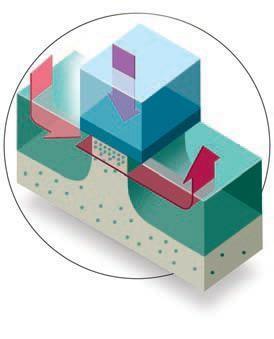
42 CMOS Processing Technology Top and side views of a typical CMOS process 44
43 CMOS Processing Technology Different layers comprising CMOS transistors 45
44 Photolithography (Lithography) Used to transfer circuit layout information to the wafer 46
45 Typical Fabrication Sequence 47
46 Self-Aligned Process Why source and drain junctions are formed after the gate oxide and polysilicon layers are deposited? 48

47 Oxide spacers and silicide Back-End Processing 49

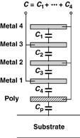
48 Back-End Processing Contact and metal layers fabrication 50

49 Back-End Processing Large contact areas should be avoided to minimize the possibility of spiking 51

50 MOS Layout - 1 It is beneficial to have some insight into the layout of the MOS devices. When laying out a design, there are many important parameters we need to pay attention to such as: drain and source areas, interconnects, and their connections to the silicon through contact windows. Design rules determine the criteria that a circuit layout must meet for a given technology. Things like, minimum length of transistors, minimum area of contact windows, 52
51 MOS Layout - 2 Example: Figures below show a circuit with a suggested layout. The same circuit can be laid out in different ways, producing different electrical parameters (such as different terminal capacitances). 53
52 Device Capacitances - 1 The quadratic model determines the DC behavior of a MOS transistor. The capacitances associated with the devices are important when studying the AC behavior of a device. There is a capacitance between any two terminals of a MOS transistor. So there are 6 Capacitances in total. The Capacitance between Drain and Source is negligible (C DS =0). These capacitances will depend on the region of operation (Bias values). 54
53 The following will be used terminals: Oxide Capacitance: Device Capacitances - 2 Depletion Capacitance: to calculate the capacitances between C 1 W L C ox C C 2 dep, W L ox Cox tox q si N su b 4 F 3. Overlap Capacitance: C 3 C 4 C ov W L D C ox C fringe 4. Junction Capacitance: Sidewall Capacitance: C jsw Bottom-plate Capacitance: C C 5 C 6 C j C jsw j C ju n C j0 V 1 R B m 55
54 In Cut-off: Device Capacitances - 3 C GS : is equal to the overlap capacitance. C GD : is equal to the overlap capacitance. C GS C GD C ov C 3 C ov C 4 C channel-bulk C GB : is equal to C gate-channel = C 1 in series with = C C SB : is equal to the junction capacitance between source and 5. bulk. C DB : is equal to the junction capacitance between source and bulk. C SB C 5 C DB C 6 56
55 Device Capacitances - 4 In Triode: The channel isolates the gate from the substrate. This means that if V G changes, the charge of the inversion layer are supplied by the drain and source as long as V DS is close to zero. So, C 1 is divided between gate and drain terminals, and gate and source terminals, and C 2 is divided between bulk and drain terminals, and bulk and source terminals C GS : C GD : C C GS GD C C ov ov C 1 2 C 1 2 C GB : the channel isolates the gate from the substrate. C GB 0 C SB : C DB : C C C SB 5 C DB 6 C 2 2 C
56 In Saturation: Device Capacitances - 5 The channel isolates the gate from the substrate. The voltage across the channel varies which can be accounted for by adding two equivalent capacitances to the source. One is between source and gate, and is equal to two thirds of C 1. The other is between source and bulk, and is equal to two thirds of C C C C 2 C GS : GS ov C GD : C GD C ov 3. C GB : the channel isolates the gate from the substrate. C GB 0 4. C SB : C C 2 SB 5 C C DB : C DB C 6 58
57 Device Capacitances - 6 In summary: Cut-off Triode Saturation C GS Cov C C 1 C 2 C ov 2 3 ov 1 C GD C ov C ov C 2 1 C ov C GB C 1 C 2 C GB C C 1 C 2 C SB C C C 2 2 C 2 C C DB C 6 C C C 6 SM 59

58 Importance of Layout Example (Folded Structure): Calculate the gate resistance of the circuits shown below. Folded structure: Decreases the drain capacitance Decreases the gate resistance Keeps the aspect ratio the same 60


59 Passive Devices Resistors 61

60 Passive Devices Capacitors: 62
61 Passive Devices Capacitors 63


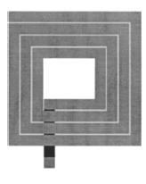
62 Passive Devices Inductors 64

63 Latch-Up Due to parasitic bipolar transistors in a CMOS process 65
64 Small Signal Models - 1 Small signal model is an approximation of the large-signal model around the operation point. In analog circuits most MOS transistors are biased in saturation region. In general, I D is a function of V GS, V DS, and V BS. We can use this Taylor series approximation: TaylorExpansion : I I I D V I D V I D V V GS V DS V BS D D0 GS DS BS second order terms I D I V D I V D V I V g V DS g V V GS V DS V BS r o D GS DS BS m GS mb BS 66
65 Current in Saturation: Small Signal Models W 2 1 W I D n C ox (V GS V TH ) n C ox 2 L' 2 L I I D D V I D I V V BS V V V Taylor approximation: D GS DS Partial Derivatives: I D V GS GS DS BS W n C ox (V GS V TH ) 1 V DS g L m 2 V GS V TH 1 V DS I D 1 W 1 C ) 2 n ox (VGS VTH I D V DS 2 L r o I D I D V TH W C ox (V GS V ) 1 V DS n TH V BS V TH V BS L 2 2 F V SB g m g m g mb 2 2 F V SB 67
66 Small-Signal Model: Small Signal Models - 3 id g m v GS v DS r o g mb v BS Terms, g m v GS and g mb v BS, can be modeled by dependent sources. These terms have the same polarity: increasing v G, has the same effect as increasing v B. The term, v DS /r o can be modeled using a resistor as shown below. 68
67 Small Signal Models - 4 Complete Small-Signal Model with Capacitances: Small signal model including all the capacitance (qualitative) analysis of even a few-transistor circuit makes the intuitive difficult! Typically, CAD tools are used for accurate circuit analysis For intuitive analysis we try to find a simplest model that can the role of each transistor with reasonable accuracy. represent 69
68 Circuit Impedance - 1 It is often useful to determine the impedance of specific pair of terminals. a circuit seen from a The following is the recipe to do so: Connect a voltage source, V X, to the port. Suppress all independent sources. Measure or calculate I X. R X V X I X 70
69 Example: Circuit Impedance - 2 Find the small-signal impedance of the following current sources. We draw the small-signal model, which is the same for both circuits, and connect a voltage source as shown below: v X i r g v X m GS o v r X o R X v X i X r o 71
70 Example: Circuit Impedance - 3 Find the small-signal impedance of the following circuits. We draw the small-signal model, which is the same for both circuits, and connect a voltage source as shown below: v X i g v g v g v g v X m GS mb BS m X mb X r r o v X v X R r X o i 1 g g g g m mb r X m mb o o 72
71 Example: Circuit Impedance - 4 Find the small-signal impedance of the following circuit. This circuit is known as the diode-connected load, and is used frequently in analog circuits. We draw source as the small-signal model and shown below: v X v X i g v g v v 1 g X m GS m X X m r r r o o o v X 1 1 R r X o i 1 g X m g m r o connect the voltage If channel length modulation is ignored (r o = ) we get: R r X o g g g m m m 73
72 Circuit Impedance - 5 Example: Find the small-signal impedance of the following circuit is a diode-connected load with body effect. circuit. This v X i g v g v g v g v X m GS mb BS m X mb X r r o v 1 g g X m mb ro v X R r r X o o i 1 g g g g g g m mb r X m mb m mb o v X o If channel length modulation is ignored (r o = ) we get: R r X o g g g g g g g g m mb m mb m mb m mb 74
73 Equivalent Transconductance - 1 Recall that the transconductance of a transistor was a a figure of merit that indicates how well the device converts a voltage to current. g m I D V V Const. GS DS It is sometimes useful to define the equivalent transconductance of a circuit as follows: I G OUT m V V Const. IN OUT The following is a small-signal block diagram of an arbitrary circuit with a Norton equivalent at the output port. We notice that: V OUT =Constant so v OUT =0 in the small signal model. G m i OUT v IN v 0 OUT 75
74 Example: Equivalent Transconductance - 2 Find the equivalent transconductance of an NMOS transistor in saturation from its small-signal model. i g v g v OUT m GS m IN G m i OUT v IN g m 76
75 Example: Equivalent Transconductance - 3 Find the equivalent transconductance of the following circuit when the NMOS transistor in saturation. v v v v i R IN GS S GS OUT S v S i R OUT i g v g v g (v i R ) g i R OUT m GS mb BS m IN OUT S mb OUT S r r O R S i 1 g R g R g v OUT m S mb S m IN ro i g g r OUT m m O G m v R 1 g R g R S r r g R g R R IN O O m S mb S S m S mb S r O O S 77
76 Short-Channel Effects Threshold Reduction Drain-induced barrier lowering (DIBL) Mobility degradation Velocity saturation Hot carrier effects Substrate current Gate current Output impedance variation 78

77 Threshold Voltage Variation in Short Channel Devices The Threshold of transistors fabricated on the same chip decreases as the channel length decreases. Intuitively, the extent of depletion regions associated with drain and source in the channel area, reduces the immobile charge that must be imaged by the charge on the gate. 79
78 Drain-Induced Barrier Lowering (DIBL) When the channel is voltage increases the short, the drain channel surface potential, lowering the barrier to flow charge from source (think of increased electric field) and therefore, decreasing the threshold. 80
79 Effects of Velocity Saturation Due to drop in mobility at high electric fields (a) Premature drain current saturation and (b) reduction in g m 81
80 Hot Carrier Effects Short channel devices may experience high lateral drain-source electric field Some carriers that make it to drain have high velocity (called hot carriers) Hot carriers may hit silicon atoms at high speed and cause impact ionization The resulting electron and holes are absorbed by the drain and substrate causing extra drain-substrate current Really hot carriers may be injected into gate oxide and flow out of gate causing gate current! 82

81 Output Impedance Variation Recall the definition of. 83
82 Output Impedance Variation in Short-Channel Devices 84
MOS Transistor Properties Review
 MOS Transistor Properties Review 1 VLSI Chip Manufacturing Process Photolithography: transfer of mask patterns to the chip Diffusion or ion implantation: selective doping of Si substrate Oxidation: SiO
ECE 342 Electronic Circuits. 3. MOS Transistors
 ECE 342 Electronic Circuits 3. MOS Transistors Jose E. Schutt-Aine Electrical & Computer Engineering University of Illinois jschutt@emlab.uiuc.edu 1 NMOS Transistor Typically L = 0.1 to 3 m, W = 0.2 to
Lecture 15: MOS Transistor models: Body effects, SPICE models. Context. In the last lecture, we discussed the modes of operation of a MOS FET:
 Lecture 15: MOS Transistor models: Body effects, SPICE models Context In the last lecture, we discussed the modes of operation of a MOS FET: oltage controlled resistor model I- curve (Square-Law Model)
MOSFET: Introduction
 E&CE 437 Integrated VLSI Systems MOS Transistor 1 of 30 MOSFET: Introduction Metal oxide semiconductor field effect transistor (MOSFET) or MOS is widely used for implementing digital designs Its major
Lecture 12: MOSFET Devices
 Lecture 12: MOSFET Devices Gu-Yeon Wei Division of Engineering and Applied Sciences Harvard University guyeon@eecs.harvard.edu Wei 1 Overview Reading S&S: Chapter 5.1~5.4 Supplemental Reading Background
The Devices. Digital Integrated Circuits A Design Perspective. Jan M. Rabaey Anantha Chandrakasan Borivoje Nikolic. July 30, 2002
 Digital Integrated Circuits A Design Perspective Jan M. Rabaey Anantha Chandrakasan Borivoje Nikolic The Devices July 30, 2002 Goal of this chapter Present intuitive understanding of device operation Introduction
ECE 342 Electronic Circuits. Lecture 6 MOS Transistors
 ECE 342 Electronic Circuits Lecture 6 MOS Transistors Jose E. Schutt-Aine Electrical & Computer Engineering University of Illinois jesa@illinois.edu 1 NMOS Transistor Typically L = 0.1 to 3 m, W = 0.2
The Devices: MOS Transistors
 The Devices: MOS Transistors References: Semiconductor Device Fundamentals, R. F. Pierret, Addison-Wesley Digital Integrated Circuits: A Design Perspective, J. Rabaey et.al. Prentice Hall NMOS Transistor
Chapter 4 Field-Effect Transistors
 Chapter 4 Field-Effect Transistors Microelectronic Circuit Design Richard C. Jaeger Travis N. Blalock 5/5/11 Chap 4-1 Chapter Goals Describe operation of MOSFETs. Define FET characteristics in operation
EE105 - Fall 2006 Microelectronic Devices and Circuits
 EE105 - Fall 2006 Microelectronic Devices and Circuits Prof. Jan M. Rabaey (jan@eecs) Lecture 7: MOS Transistor Some Administrative Issues Lab 2 this week Hw 2 due on We Hw 3 will be posted same day MIDTERM
Microelectronics Part 1: Main CMOS circuits design rules
 GBM8320 Dispositifs Médicaux telligents Microelectronics Part 1: Main CMOS circuits design rules Mohamad Sawan et al. Laboratoire de neurotechnologies Polystim! http://www.cours.polymtl.ca/gbm8320/! med-amine.miled@polymtl.ca!
EE105 - Fall 2005 Microelectronic Devices and Circuits
 EE105 - Fall 005 Microelectronic Devices and Circuits ecture 7 MOS Transistor Announcements Homework 3, due today Homework 4 due next week ab this week Reading: Chapter 4 1 ecture Material ast lecture
Device Models (PN Diode, MOSFET )
") Device Models (PN Diode, MOSFET ) Instructor: Steven P. Levitan steve@ece.pitt.edu TA: Gayatri Mehta, José Martínez Book: Digital Integrated Circuits: A Design Perspective; Jan Rabaey Lab Notes: Handed
Device Models (PN Diode, MOSFET ) Instructor: Steven P. Levitan steve@ece.pitt.edu TA: Gayatri Mehta, José Martínez Book: Digital Integrated Circuits: A Design Perspective; Jan Rabaey Lab Notes: Handed
MOS Transistor I-V Characteristics and Parasitics
 ECEN454 Digital Integrated Circuit Design MOS Transistor I-V Characteristics and Parasitics ECEN 454 Facts about Transistors So far, we have treated transistors as ideal switches An ON transistor passes
ECE 546 Lecture 10 MOS Transistors
 ECE 546 Lecture 10 MOS Transistors Spring 2018 Jose E. Schutt-Aine Electrical & Computer Engineering University of Illinois jesa@illinois.edu NMOS Transistor NMOS Transistor N-Channel MOSFET Built on p-type
6.012 Electronic Devices and Circuits Spring 2005
 6.012 Electronic Devices and Circuits Spring 2005 May 16, 2005 Final Exam (200 points) -OPEN BOOK- Problem NAME RECITATION TIME 1 2 3 4 5 Total General guidelines (please read carefully before starting):
Digital Integrated Circuits A Design Perspective. Jan M. Rabaey Anantha Chandrakasan Borivoje Nikolic. The Devices. July 30, Devices.
 Digital Integrated Circuits A Design Perspective Jan M. Rabaey Anantha Chandrakasan Borivoje Nikolic The July 30, 2002 1 Goal of this chapter Present intuitive understanding of device operation Introduction
EEC 118 Lecture #2: MOSFET Structure and Basic Operation. Rajeevan Amirtharajah University of California, Davis Jeff Parkhurst Intel Corporation
 EEC 118 Lecture #2: MOSFET Structure and Basic Operation Rajeevan Amirtharajah University of California, Davis Jeff Parkhurst Intel Corporation Announcements Lab 1 this week, report due next week Bring
The Devices. Digital Integrated Circuits A Design Perspective. Jan M. Rabaey Anantha Chandrakasan Borivoje Nikolic. July 30, 2002
 igital Integrated Circuits A esign Perspective Jan M. Rabaey Anantha Chandrakasan Borivoje Nikolic The evices July 30, 2002 Goal of this chapter Present intuitive understanding of device operation Introduction
FIELD-EFFECT TRANSISTORS
 FIEL-EFFECT TRANSISTORS 1 Semiconductor review 2 The MOS capacitor 2 The enhancement-type N-MOS transistor 3 I-V characteristics of enhancement MOSFETS 4 The output characteristic of the MOSFET in saturation
MOS Transistor Theory
 CHAPTER 3 MOS Transistor Theory Outline 2 1. Introduction 2. Ideal I-V Characteristics 3. Nonideal I-V Effects 4. C-V Characteristics 5. DC Transfer Characteristics 6. Switch-level RC Delay Models MOS
Practice 3: Semiconductors
 Practice 3: Semiconductors Digital Electronic Circuits Semester A 2012 VLSI Fabrication Process VLSI Very Large Scale Integration The ability to fabricate many devices on a single substrate within a given
Integrated Circuits & Systems
 Federal University of Santa Catarina Center for Technology Computer Science & Electronics Engineering Integrated Circuits & Systems INE 5442 Lecture 10 MOSFET part 1 guntzel@inf.ufsc.br ual-well Trench-Isolated
ECE315 / ECE515 Lecture-2 Date:
 Lecture-2 Date: 04.08.2016 NMOS I/V Characteristics Discussion on I/V Characteristics MOSFET Second Order Effect NMOS I-V Characteristics ECE315 / ECE515 Gradual Channel Approximation: Cut-off Linear/Triode
Chapter 13 Small-Signal Modeling and Linear Amplification
 Chapter 13 Small-Signal Modeling and Linear Amplification Microelectronic Circuit Design Richard C. Jaeger Travis N. Blalock 1/4/12 Chap 13-1 Chapter Goals Understanding of concepts related to: Transistors
Lecture 12: MOS Capacitors, transistors. Context
 Lecture 12: MOS Capacitors, transistors Context In the last lecture, we discussed PN diodes, and the depletion layer into semiconductor surfaces. Small signal models In this lecture, we will apply those
Electronic Circuits 1. Transistor Devices. Contents BJT and FET Characteristics Operations. Prof. C.K. Tse: Transistor devices
 Electronic Circuits 1 Transistor Devices Contents BJT and FET Characteristics Operations 1 What is a transistor? Three-terminal device whose voltage-current relationship is controlled by a third voltage
ECEN474/704: (Analog) VLSI Circuit Design Spring 2018
 VLSI Circuit Design Spring 2018") ECEN474/704: (Analog) SI Circuit Design Spring 2018 ecture 2: MOS ransistor Modeling Sam Palermo Analog & Mixed-Signal Center exas A&M University Announcements If you haven t already, turn in your 0.18um
ECEN474/704: (Analog) SI Circuit Design Spring 2018 ecture 2: MOS ransistor Modeling Sam Palermo Analog & Mixed-Signal Center exas A&M University Announcements If you haven t already, turn in your 0.18um
ECE 497 JS Lecture - 12 Device Technologies
 ECE 497 JS Lecture - 12 Device Technologies Spring 2004 Jose E. Schutt-Aine Electrical & Computer Engineering University of Illinois jose@emlab.uiuc.edu 1 NMOS Transistor 2 ρ Source channel charge density
Lecture 3: CMOS Transistor Theory
 Lecture 3: CMOS Transistor Theory Outline Introduction MOS Capacitor nmos I-V Characteristics pmos I-V Characteristics Gate and Diffusion Capacitance 2 Introduction So far, we have treated transistors
CMPEN 411 VLSI Digital Circuits. Lecture 03: MOS Transistor
 CMPEN 411 VLSI Digital Circuits Lecture 03: MOS Transistor Kyusun Choi [Adapted from Rabaey s Digital Integrated Circuits, Second Edition, 2003 J. Rabaey, A. Chandrakasan, B. Nikolic] CMPEN 411 L03 S.1
LECTURE 3 MOSFETS II. MOS SCALING What is Scaling?
 LECTURE 3 MOSFETS II Lecture 3 Goals* * Understand constant field and constant voltage scaling and their effects. Understand small geometry effects for MOS transistors and their implications modeling and
MOS Transistor Theory
 MOS Transistor Theory So far, we have viewed a MOS transistor as an ideal switch (digital operation) Reality: less than ideal EE 261 Krish Chakrabarty 1 Introduction So far, we have treated transistors
EE5311- Digital IC Design
 EE5311- Digital IC Design Module 1 - The Transistor Janakiraman V Assistant Professor Department of Electrical Engineering Indian Institute of Technology Madras Chennai October 28, 2017 Janakiraman, IITM
Metal-oxide-semiconductor field effect transistors (2 lectures)
") Metal-ide-semiconductor field effect transistors ( lectures) MOS physics (brief in book) Current-voltage characteristics - pinch-off / channel length modulation - weak inversion - velocity saturation -
Metal-ide-semiconductor field effect transistors ( lectures) MOS physics (brief in book) Current-voltage characteristics - pinch-off / channel length modulation - weak inversion - velocity saturation -
MOS Transistors. Prof. Krishna Saraswat. Department of Electrical Engineering Stanford University Stanford, CA
 MOS Transistors Prof. Krishna Saraswat Department of Electrical Engineering S Stanford, CA 94305 saraswat@stanford.edu 1 1930: Patent on the Field-Effect Transistor! Julius Lilienfeld filed a patent describing
The Devices. Jan M. Rabaey
 The Devices Jan M. Rabaey Goal of this chapter Present intuitive understanding of device operation Introduction of basic device equations Introduction of models for manual analysis Introduction of models
Lecture 04 Review of MOSFET
 ECE 541/ME 541 Microelectronic Fabrication Techniques Lecture 04 Review of MOSFET Zheng Yang (ERF 3017, email: yangzhen@uic.edu) What is a Transistor? A Switch! An MOS Transistor V GS V T V GS S Ron D
Lecture 11: MOS Transistor
 Lecture 11: MOS Transistor Prof. Niknejad Lecture Outline Review: MOS Capacitors Regions MOS Capacitors (3.8 3.9) CV Curve Threshold Voltage MOS Transistors (4.1 4.3): Overview Cross-section and layout
ELEC 3908, Physical Electronics, Lecture 26. MOSFET Small Signal Modelling
 ELEC 3908, Physical Electronics, Lecture 26 MOSFET Small Signal Modelling Lecture Outline MOSFET small signal behavior will be considered in the same way as for the diode and BJT Capacitances will be considered
ELEN0037 Microelectronic IC Design. Prof. Dr. Michael Kraft
 ELEN0037 Microelectronic IC Design Prof. Dr. Michael Kraft Lecture 2: Technological Aspects Technology Passive components Active components CMOS Process Basic Layout Scaling CMOS Technology Integrated
Fundamentals of the Metal Oxide Semiconductor Field-Effect Transistor
 Triode Working FET Fundamentals of the Metal Oxide Semiconductor Field-Effect Transistor The characteristics of energy bands as a function of applied voltage. Surface inversion. The expression for the
Lecture 10 MOSFET (III) MOSFET Equivalent Circuit Models
 MOSFET Equivalent Circuit Models") Lecture 10 MOSFET (III) MOSFET Equivalent Circuit Models Outline Lowfrequency smallsignal equivalent circuit model Highfrequency smallsignal equivalent circuit model Reading Assignment: Howe and Sodini;
Lecture 10 MOSFET (III) MOSFET Equivalent Circuit Models Outline Lowfrequency smallsignal equivalent circuit model Highfrequency smallsignal equivalent circuit model Reading Assignment: Howe and Sodini;
Quantitative MOSFET. Step 1. Connect the MOS capacitor results for the electron charge in the inversion layer Q N to the drain current.
 Quantitative MOSFET Step 1. Connect the MOS capacitor results for the electron charge in the inversion layer Q N to the drain current. V DS _ n source polysilicon gate y = y * 0 x metal interconnect to
Today s lecture. EE141- Spring 2003 Lecture 4. Design Rules CMOS Inverter MOS Transistor Model
 - Spring 003 Lecture 4 Design Rules CMOS Inverter MOS Transistor Model Today s lecture Design Rules The CMOS inverter at a glance An MOS transistor model for manual analysis Important! Labs start next
Lecture 4: CMOS Transistor Theory
 Introduction to CMOS VLSI Design Lecture 4: CMOS Transistor Theory David Harris, Harvey Mudd College Kartik Mohanram and Steven Levitan University of Pittsburgh Outline q Introduction q MOS Capacitor q
EE382M-14 CMOS Analog Integrated Circuit Design
 EE382M-14 CMOS Analog Integrated Circuit Design Lecture 3, MOS Capacitances, Passive Components, and Layout of Analog Integrated Circuits MOS Capacitances Type of MOS transistor capacitors Depletion capacitance
EECS240 Spring Today s Lecture. Lecture 2: CMOS Technology and Passive Devices. Lingkai Kong EECS. EE240 CMOS Technology
 EECS240 Spring 2013 Lecture 2: CMOS Technology and Passive Devices Lingkai Kong EECS Today s Lecture EE240 CMOS Technology Passive devices Motivation Resistors Capacitors (Inductors) Next time: MOS transistor
EE115C Winter 2017 Digital Electronic Circuits. Lecture 3: MOS RC Model, CMOS Manufacturing
 EE115C Winter 2017 Digital Electronic Circuits Lecture 3: MOS RC Model, CMOS Manufacturing Agenda MOS Transistor: RC Model (pp. 104-113) S R on D CMOS Manufacturing Process (pp. 36-46) S S C GS G G C GD
ECE-305: Fall 2017 MOS Capacitors and Transistors
 ECE-305: Fall 2017 MOS Capacitors and Transistors Pierret, Semiconductor Device Fundamentals (SDF) Chapters 15+16 (pp. 525-530, 563-599) Professor Peter Bermel Electrical and Computer Engineering Purdue
EE105 Fall 2014 Microelectronic Devices and Circuits. NMOS Transistor Capacitances: Saturation Region
 EE105 Fall 014 Microelectronic Devices and Circuits Prof. Ming C. Wu wu@eecs.berkeley.edu 511 Sutardja Dai Hall (SDH) 1 NMOS Transistor Capacitances: Saturation Region Drain no longer connected to channel
Lecture 5: CMOS Transistor Theory
 Lecture 5: CMOS Transistor Theory Slides courtesy of Deming Chen Slides based on the initial set from David Harris CMOS VLSI Design Outline q q q q q q q Introduction MOS Capacitor nmos I-V Characteristics
Figure 1: MOSFET symbols.
 c Copyright 2008. W. Marshall Leach, Jr., Professor, Georgia Institute of Technology, School of Electrical and Computer Engineering. The MOSFET Device Symbols Whereas the JFET has a diode junction between
MOSFET Physics: The Long Channel Approximation
 MOSFET Physics: The ong Channel Approximation A basic n-channel MOSFET (Figure 1) consists of two heavily-doped n-type regions, the Source and Drain, that comprise the main terminals of the device. The
Lecture 10 MOSFET (III) MOSFET Equivalent Circuit Models
 MOSFET Equivalent Circuit Models") Lecture 1 MOSFET (III) MOSFET Equivalent Circuit Models Outline Lowfrequency smallsignal equivalent circuit model Highfrequency smallsignal equivalent circuit model Reading Assignment: Howe and Sodini;
Lecture 1 MOSFET (III) MOSFET Equivalent Circuit Models Outline Lowfrequency smallsignal equivalent circuit model Highfrequency smallsignal equivalent circuit model Reading Assignment: Howe and Sodini;
CMOS INVERTER. Last Lecture. Metrics for qualifying digital circuits. »Cost» Reliability» Speed (delay)»performance
»performance") CMOS INVERTER Last Lecture Metrics for qualifying digital circuits»cost» Reliability» Speed (delay)»performance 1 Today s lecture The CMOS inverter at a glance An MOS transistor model for manual analysis
CMOS INVERTER Last Lecture Metrics for qualifying digital circuits»cost» Reliability» Speed (delay)»performance 1 Today s lecture The CMOS inverter at a glance An MOS transistor model for manual analysis
Microelectronics Main CMOS design rules & basic circuits
 GBM8320 Dispositifs médicaux intelligents Microelectronics Main CMOS design rules & basic circuits Mohamad Sawan et al. Laboratoire de neurotechnologies Polystim mohamad.sawan@polymtl.ca M5418 6 & 7 September
CMOS Devices. PN junctions and diodes NMOS and PMOS transistors Resistors Capacitors Inductors Bipolar transistors
 CMOS Devices PN junctions and diodes NMOS and PMOS transistors Resistors Capacitors Inductors Bipolar transistors PN Junctions Diffusion causes depletion region D.R. is insulator and establishes barrier
MOSFET Capacitance Model
 MOSFET Capacitance Model So far we discussed the MOSFET DC models. In real circuit operation, the device operates under time varying terminal voltages and the device operation can be described by: 1 small
ELEC 3908, Physical Electronics, Lecture 23. The MOSFET Square Law Model
 ELEC 3908, Physical Electronics, Lecture 23 The MOSFET Square Law Model Lecture Outline As with the diode and bipolar, have looked at basic structure of the MOSFET and now turn to derivation of a current
Lecture 15 OUTLINE. MOSFET structure & operation (qualitative) Review of electrostatics The (N)MOS capacitor
 Review of electrostatics The (N)MOS capacitor") Lecture 15 OUTLINE MOSFET structure & operation (qualitative) Review of electrostatics The (N)MOS capacitor Electrostatics t ti Charge vs. voltage characteristic Reading: Chapter 6.1 6.2.1 EE105 Fall 2007
Lecture 15 OUTLINE MOSFET structure & operation (qualitative) Review of electrostatics The (N)MOS capacitor Electrostatics t ti Charge vs. voltage characteristic Reading: Chapter 6.1 6.2.1 EE105 Fall 2007
Lecture 23: Negative Resistance Osc, Differential Osc, and VCOs
 EECS 142 Lecture 23: Negative Resistance Osc, Differential Osc, and VCOs Prof. Ali M. Niknejad University of California, Berkeley Copyright c 2005 by Ali M. Niknejad A. M. Niknejad University of California,
P. R. Nelson 1 ECE418 - VLSI. Midterm Exam. Solutions
 P. R. Nelson 1 ECE418 - VLSI Midterm Exam Solutions 1. (8 points) Draw the cross-section view for A-A. The cross-section view is as shown below.. ( points) Can you tell which of the metal1 regions is the
6.012 Electronic Devices and Circuits
 Page 1 of 12 YOUR NAME Department of Electrical Engineering and Computer Science Massachusetts Institute of Technology 6.012 Electronic Devices and Circuits FINAL EXAMINATION Open book. Notes: 1. Unless
Section 12: Intro to Devices
 Section 12: Intro to Devices Extensive reading materials on reserve, including Robert F. Pierret, Semiconductor Device Fundamentals EE143 Ali Javey Bond Model of Electrons and Holes Si Si Si Si Si Si Si
Circuits. L2: MOS Models-2 (1 st Aug. 2013) B. Mazhari Dept. of EE, IIT Kanpur. B. Mazhari, IITK. G-Number
 B. Mazhari Dept. of EE, IIT Kanpur. B. Mazhari, IITK. G-Number") EE610: CMOS Analog Circuits L: MOS Models- (1 st Aug. 013) B. Mazhari Dept. of EE, IIT Kanpur 3 NMOS Models MOS MODEL Above Threshold Subthreshold ( GS > TN ) ( GS < TN ) Saturation ti Ti Triode ( DS >
EE610: CMOS Analog Circuits L: MOS Models- (1 st Aug. 013) B. Mazhari Dept. of EE, IIT Kanpur 3 NMOS Models MOS MODEL Above Threshold Subthreshold ( GS > TN ) ( GS < TN ) Saturation ti Ti Triode ( DS >
6.012 Electronic Devices and Circuits
 Page 1 of 10 YOUR NAME Department of Electrical Engineering and Computer Science Massachusetts Institute of Technology 6.012 Electronic Devices and Circuits Exam No. 2 Thursday, November 5, 2009 7:30 to
Final Examination EE 130 December 16, 1997 Time allotted: 180 minutes
 Final Examination EE 130 December 16, 1997 Time allotted: 180 minutes Problem 1: Semiconductor Fundamentals [30 points] A uniformly doped silicon sample of length 100µm and cross-sectional area 100µm 2
ESE 570: Digital Integrated Circuits and VLSI Fundamentals
 ESE 570: Digital Integrated Circuits and VLSI Fundamentals Lec 4: January 23, 2018 MOS Transistor Theory, MOS Model Penn ESE 570 Spring 2018 Khanna Lecture Outline! CMOS Process Enhancements! Semiconductor
Operation and Modeling of. The MOS Transistor. Second Edition. Yannis Tsividis Columbia University. New York Oxford OXFORD UNIVERSITY PRESS
 Operation and Modeling of The MOS Transistor Second Edition Yannis Tsividis Columbia University New York Oxford OXFORD UNIVERSITY PRESS CONTENTS Chapter 1 l.l 1.2 1.3 1.4 1.5 1.6 1.7 Chapter 2 2.1 2.2
Chapter 2 CMOS Transistor Theory. Jin-Fu Li Department of Electrical Engineering National Central University Jungli, Taiwan
 Chapter 2 CMOS Transistor Theory Jin-Fu Li Department of Electrical Engineering National Central University Jungli, Taiwan Outline Introduction MOS Device Design Equation Pass Transistor Jin-Fu Li, EE,
Lecture 15 OUTLINE. MOSFET structure & operation (qualitative) Review of electrostatics The (N)MOS capacitor
 Review of electrostatics The (N)MOS capacitor") Lecture 15 OUTLINE MOSFET structure & operation (qualitative) Review of electrostatics The (N)MOS capacitor Electrostatics Charge vs. voltage characteristic Reading: Chapter 6.1 6.2.1 EE15 Spring 28 Lecture
Lecture 15 OUTLINE MOSFET structure & operation (qualitative) Review of electrostatics The (N)MOS capacitor Electrostatics Charge vs. voltage characteristic Reading: Chapter 6.1 6.2.1 EE15 Spring 28 Lecture
VLSI Design and Simulation
 VLSI Design and Simulation Performance Characterization Topics Performance Characterization Resistance Estimation Capacitance Estimation Inductance Estimation Performance Characterization Inverter Voltage
! PN Junction. ! MOS Transistor Topology. ! Threshold. ! Operating Regions. " Resistive. " Saturation. " Subthreshold (next class)
") ESE370: ircuitlevel Modeling, Design, and Optimization for Digital Systems Lec 7: September 20, 2017 MOS Transistor Operating Regions Part 1 Today! PN Junction! MOS Transistor Topology! Threshold! Operating
ESE370: ircuitlevel Modeling, Design, and Optimization for Digital Systems Lec 7: September 20, 2017 MOS Transistor Operating Regions Part 1 Today! PN Junction! MOS Transistor Topology! Threshold! Operating
Lecture 210 Physical Aspects of ICs (12/15/01) Page 210-1
 Page 210-1") Lecture 210 Physical Aspects of ICs (12/15/01) Page 210-1 LECTURE 210 PHYSICAL ASPECTS OF ICs (READING: Text-Sec. 2.5, 2.6, 2.8) INTRODUCTION Objective Illustrate the physical aspects of integrated circuits
Lecture 210 Physical Aspects of ICs (12/15/01) Page 210-1 LECTURE 210 PHYSICAL ASPECTS OF ICs (READING: Text-Sec. 2.5, 2.6, 2.8) INTRODUCTION Objective Illustrate the physical aspects of integrated circuits
Semiconductor Physics fall 2012 problems
 Semiconductor Physics fall 2012 problems 1. An n-type sample of silicon has a uniform density N D = 10 16 atoms cm -3 of arsenic, and a p-type silicon sample has N A = 10 15 atoms cm -3 of boron. For each
ESE 570: Digital Integrated Circuits and VLSI Fundamentals
 ESE 570: Digital Integrated Circuits and VLSI Fundamentals Lec 4: January 29, 2019 MOS Transistor Theory, MOS Model Penn ESE 570 Spring 2019 Khanna Lecture Outline! CMOS Process Enhancements! Semiconductor
VLSI Design The MOS Transistor
 VLSI Design The MOS Transistor Frank Sill Torres Universidade Federal de Minas Gerais (UFMG), Brazil VLSI Design: CMOS Technology 1 Outline Introduction MOS Capacitor nmos I-V Characteristics pmos I-V
A Compact Analytical Modelling of the Electrical Characteristics of Submicron Channel MOSFETs
 ROMANIAN JOURNAL OF INFORMATION SCIENCE AND TECHNOLOGY Volume 11, Number 4, 2008, 383 395 A Compact Analytical Modelling of the Electrical Characteristics of Submicron Channel MOSFETs Andrei SEVCENCO,
ECE321 Electronics I
 EE31 Electronics I Lecture 8: MOSET Threshold Voltage and Parasitic apacitances Payman Zarkesh-Ha Office: EE Bldg. 3B Office hours: Tuesday :-3:PM or by appointment E-mail: payman@ece.unm.edu Slide: 1
Field-Effect (FET) transistors
 transistors") Field-Effect (FET) transistors References: Barbow (Chapter 8), Rizzoni (chapters 8 & 9) In a field-effect transistor (FET), the width of a conducting channel in a semiconductor and, therefore, its current-carrying
Field-Effect (FET) transistors References: Barbow (Chapter 8), Rizzoni (chapters 8 & 9) In a field-effect transistor (FET), the width of a conducting channel in a semiconductor and, therefore, its current-carrying
ECE 415/515 ANALOG INTEGRATED CIRCUIT DESIGN
 ECE 415/515 ANALOG INTEGRATED CIRCUIT DESIGN CMOS PROCESS CHARACTERIZATION VISHAL SAXENA VSAXENA@UIDAHO.EDU Vishal Saxena DESIGN PARAMETERS Analog circuit designers care about: Open-loop Gain: g m r o
CMOS Cross Section. EECS240 Spring Dimensions. Today s Lecture. Why Talk About Passives? EE240 Process
 EECS240 Spring 202 CMOS Cross Section Metal p - substrate p + diffusion Lecture 2: CMOS Technology and Passive Devices Poly n - well n + diffusion Elad Alon Dept. of EECS EECS240 Lecture 2 4 Today s Lecture
Microelectronic Devices and Circuits Lecture 13 - Linear Equivalent Circuits - Outline Announcements Exam Two -
 6.012 Microelectronic Devices and Circuits Lecture 13 Linear Equivalent Circuits Outline Announcements Exam Two Coming next week, Nov. 5, 7:309:30 p.m. Review Subthreshold operation of MOSFETs Review Large
The Devices. Devices
 The The MOS Transistor Gate Oxyde Gate Source n+ Polysilicon Drain n+ Field-Oxyde (SiO 2 ) p-substrate p+ stopper Bulk Contact CROSS-SECTION of NMOS Transistor Cross-Section of CMOS Technology MOS transistors
UNIVERSITY OF CALIFORNIA College of Engineering Department of Electrical Engineering and Computer Sciences. EECS 130 Professor Ali Javey Fall 2006
 UNIVERSITY OF CALIFORNIA College of Engineering Department of Electrical Engineering and Computer Sciences EECS 130 Professor Ali Javey Fall 2006 Midterm 2 Name: SID: Closed book. Two sheets of notes are
Department of Electrical and Computer Engineering, Cornell University. ECE 3150: Microelectronics. Spring Due on March 01, 2018 at 7:00 PM
 Department of Electrical and Computer Engineering, Cornell University ECE 3150: Microelectronics Spring 2018 Homework 4 Due on March 01, 2018 at 7:00 PM Suggested Readings: a) Lecture notes Important Note:
Lecture #27. The Short Channel Effect (SCE)
") Lecture #27 ANNOUNCEMENTS Design Project: Your BJT design should meet the performance specifications to within 10% at both 300K and 360K. ( β dc > 45, f T > 18 GHz, V A > 9 V and V punchthrough > 9 V )
Lecture #27 ANNOUNCEMENTS Design Project: Your BJT design should meet the performance specifications to within 10% at both 300K and 360K. ( β dc > 45, f T > 18 GHz, V A > 9 V and V punchthrough > 9 V )
II III IV V VI B C N. Al Si P S. Zn Ga Ge As Se Cd In Sn Sb Te. Silicon (Si) the dominating material in IC manufacturing
 the dominating material in IC manufacturing") II III IV V VI B N Al Si P S Zn Ga Ge As Se d In Sn Sb Te Silicon (Si) the dominating material in I manufacturing ompound semiconductors III - V group: GaAs GaN GaSb GaP InAs InP InSb... The Energy Band
II III IV V VI B N Al Si P S Zn Ga Ge As Se d In Sn Sb Te Silicon (Si) the dominating material in I manufacturing ompound semiconductors III - V group: GaAs GaN GaSb GaP InAs InP InSb... The Energy Band
Electronics Fets and Mosfets Prof D C Dube Department of Physics Indian Institute of Technology, Delhi
 Electronics Fets and Mosfets Prof D C Dube Department of Physics Indian Institute of Technology, Delhi Module No. #05 Lecture No. #02 FETS and MOSFETS (contd.) In the previous lecture, we studied the working
University of Pennsylvania Department of Electrical Engineering. ESE 570 Midterm Exam March 14, 2013 FORMULAS AND DATA
 University of Pennsylvania Department of Electrical Engineering ESE 570 Midterm Exam March 4, 03 FORMULAS AND DATA. PHYSICAL CONSTANTS: n i = intrinsic concentration undoped) silicon =.45 x 0 0 cm -3 @
EE 560 MOS TRANSISTOR THEORY PART 2. Kenneth R. Laker, University of Pennsylvania
 1 EE 560 MOS TRANSISTOR THEORY PART nmos TRANSISTOR IN LINEAR REGION V S = 0 V G > V T0 channel SiO V D = small 4 C GC C BC substrate depletion region or bulk B p nmos TRANSISTOR AT EDGE OF SATURATION
Lecture 13 MOSFET as an amplifier with an introduction to MOSFET small-signal model and small-signal schematics. Lena Peterson
 Lecture 13 MOSFET as an amplifier with an introduction to MOSFET small-signal model and small-signal schematics Lena Peterson 2015-10-13 Outline (1) Why is the CMOS inverter gain not infinite? Large-signal
MOS Transistor Theory MOSFET Symbols Current Characteristics of MOSFET. MOS Symbols and Characteristics. nmos Enhancement Transistor
 MOS Transistor Theory MOSFET Symbols Current Characteristics of MOSFET Calculation of t and Important 2 nd Order Effects SmallSignal Signal MOSFET Model Summary Material from: CMOS LSI Design By Weste
Field effect = Induction of an electronic charge due to an electric field Example: Planar capacitor
 JFETs AND MESFETs Introduction Field effect = Induction of an electronic charge due to an electric field Example: Planar capacitor Why would an FET made of a planar capacitor with two metal plates, as
Lecture 11: J-FET and MOSFET
 ENE 311 Lecture 11: J-FET and MOSFET FETs vs. BJTs Similarities: Amplifiers Switching devices Impedance matching circuits Differences: FETs are voltage controlled devices. BJTs are current controlled devices.
1. The MOS Transistor. Electrical Conduction in Solids
 Electrical Conduction in Solids!The band diagram describes the energy levels for electron in solids.!the lower filled band is named Valence Band.!The upper vacant band is named conduction band.!the distance
SECTION: Circle one: Alam Lundstrom. ECE 305 Exam 5 SOLUTIONS: Spring 2016 April 18, 2016 M. A. Alam and M.S. Lundstrom Purdue University
 NAME: PUID: SECTION: Circle one: Alam Lundstrom ECE 305 Exam 5 SOLUTIONS: April 18, 2016 M A Alam and MS Lundstrom Purdue University This is a closed book exam You may use a calculator and the formula
EE 240B Spring Advanced Analog Integrated Circuits Lecture 2: MOS Transistor Models. Elad Alon Dept. of EECS
 EE 240B Spring 2018 Advanced Analog Integrated Circuits Lecture 2: MOS Transistor Models Elad Alon Dept. of EECS Square Law Model? Assumptions made to come up with this model: Charge density determined