Chapter 10: Sinusoidal Steady-State Analysis
|
|
|
- Avis King
- 5 years ago
- Views:
Transcription
1 Chapter 10: Sinusoidal Steady-State Analysis Basic Approach Nodal Analysis Mesh Analysis Superposition Theorem Source Transformation Thevenin & Norton Equivalent Circuits Applications Summary 1
2 10.1 Basic Approach 3 Steps to Analyze AC Circuits: 1. Transform the circuit to the phasor or frequency domain. 2. Solve the problem using circuit techniques (nodal analysis, mesh analysis, superposition, etc.). 3. Transform the resulting phasor to the time domain. Time to Freq Phasor Laplace xform Fourier xform Solve variables in Freq Phasor Inv. Laplace xform Fourier xform Freq to Time Sinusoidal Steady-State Analysis: Frequency domain analysis of AC circuit via phasors is much easier than analysis of the circuit in the time domain. 2
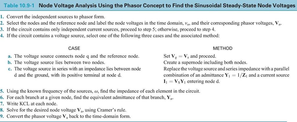
3 The basis of Nodal Analysis is KCL Nodal Analysis Example: Using nodal analysis, find V o. 3
4 The basis of Nodal Analysis is KCL Nodal Analysis Example: Using nodal analysis, find i o. 4
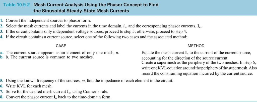
5 10.3 Mesh Analysis The basic of Mesh Analysis is KVL. Example: Find I o in the following figure using mesh analysis. (This problem was previously solved using Nodal analysis.) 5
6 10.3 Mesh Analysis The basic of Mesh Analysis is KVL. Example: Solve for i o using mesh analysis. 6
7 5
8 10.4 Superposition Theorem When a circuit has sources operating at different frequencies, The separate phasor circuit for each frequency must be solved independently, and The total response is the sum of time-domain responses of all the individual phasor circuits. Example: Calculate v o in the circuit using the superposition theorem. 6
9 4.3 Superposition Theorem (1) - Superposition states that the voltage across (or current through) an element in a linear circuit is the algebraic sum of the voltage across (or currents through) that element due to EACH independent source acting alone. - The principle of superposition helps us to analyze a linear circuit with more than one independent source by calculating the contribution of each independent source separately. - Steps to Apply Superposition Principle: 1. Turn off all indep. sources except one source. Find the output (v or i) due to that active source using techniques from earlier in the course. 2. Repeat Step 1 for each of the other indep. sources. 3. Find total contribution by adding all contributions from indep. sources. Note: In Step 1, this implies that we replace every voltage source by 0 V (or a short circuit), and every current source by 0 A (or an open circuit). Dependent sources are left intact because they are controlled by others.7
10 10.5 Source Transformation (1) Example: Find v o using the concept of source transformation. 1 0
11
12 4.4 Source Transformation (1) - Like series-parallel combination and wye-delta transformation, source transformation is another tool for simplifying circuits. - An equivalent circuit is one whose v-i characteristics are identical with the original circuit. - A source transformation is the process of replacing a voltage source v s in series with a resistor R by a current source i s in parallel with a resistor R, and vice versa. Transformation of independent sources Transformation of dependent sources The arrow of the current source is directed toward the positive terminal of the voltage source. The source transformation is not possible when R = 0 for voltage source and R = for current source. 10
13 4.4 Source Transformation (2) A voltage source v s connected in series with a resistor R s and a current source i s is connected in parallel with a resistor R p are equivalent circuits provided that R p R s & v s R s i s 11
14 10.6 Thevenin & Norton Equivalent Circuits Thevenin Equivalent Norton Equivalent Example: Find the Thevenin equivalent at terminals a b. 1 2
15 4.5 Thevenin s Theorem (1) It states that a linear two-terminal circuit (Fig. a) can be replaced by an equivalent circuit (Fig. b) consisting of a voltage source V Th in series with a resistor R Th, where V Th is the open-circuit voltage at the terminals. R Th is the input or equivalent resistance at the terminals when the independent sources are turned off. 13
16 To find R Th : 4.5 Thevenin s Theorem (2) Case 1: If the network has no dependent sources, we turn off all indep. Source. R Th is the input resistance of the network looking btw terminals a & b. Case 2: If the network has depend. Sources. Depend. sources are not to be turned off because they are controlled by circuit variables. (a) Apply v o at a & b and determine the resulting i o. Then R Th = v o /i o. Alternatively, (b) insert i o at a & b and determine v o. Again R Th = v o /i o. (a) (b) 4 1
17 4.6 Norton s Theorem (1) It states that a linear two-terminal circuit (Fig. a) can be replaced by an equivalent circuit (Fig. b) consisting of a current source I N in parallel with a resistor R N, (a) (b) where I N is the short-circuit current through the terminals. R N is the input or equivalent resistance at the terminals when the indepen. sources are turned off. 15

18 10.9 Summary (1) With the pervasive use of ac electric power in the home and industry, it is important for engineers to analyze circuits with sinusoidal independent sources. The steady-state response of a linear circuit to a sinusoidal input is itself a sinusoid having the same frequency as the input signal. Circuits that contain inductors and capacitors are represented by differential equations. When the input to the circuit is sinusoidal, the phasors and impedances can be used to represent the circuit in the frequency domain. In the frequency domain, the circuit is represented by algebraic equations. The steady-state response of a linear circuit with a sinusoidal input is obtained as follows: 1. Transform the circuit into the frequency domain, using phasors and impedances.
19 10.9 Summary (2) 2. Represent the frequency-domain circuit by algebraic equation, for example, mesh or node equations. 3. Solve the algebraic equations to obtain the response of the circuit. 4. Transform the response into the time domain, using phasors. A circuit contains several sinusoidal sources, two cases: When all of the sinusoidal sources have the same frequency, the response will be a sinusoid with that frequency, and the problem can be solved in the same way that it would be if there was only one source. When the sinusoidal sources have different frequencies, superposition is used to break the time-domain circuit up into several circuits, each with sinusoidal inputs all at the same frequency. Each of the separate circuits is analyzed separately and the responses are summed in the time domain.
Electric Circuits II Sinusoidal Steady State Analysis. Dr. Firas Obeidat
 Electric Circuits II Sinusoidal Steady State Analysis Dr. Firas Obeidat 1 Table of Contents 1 2 3 4 5 Nodal Analysis Mesh Analysis Superposition Theorem Source Transformation Thevenin and Norton Equivalent
Chapter 10 Sinusoidal Steady State Analysis Chapter Objectives:
 Chapter 10 Sinusoidal Steady State Analysis Chapter Objectives: Apply previously learn circuit techniques to sinusoidal steady-state analysis. Learn how to apply nodal and mesh analysis in the frequency
Sinusoidal Steady State Analysis (AC Analysis) Part I
 Part I") Sinusoidal Steady State Analysis (AC Analysis) Part I Amin Electronics and Electrical Communications Engineering Department (EECE) Cairo University elc.n102.eng@gmail.com http://scholar.cu.edu.eg/refky/
Sinusoidal Steady State Analysis (AC Analysis) Part I Amin Electronics and Electrical Communications Engineering Department (EECE) Cairo University elc.n102.eng@gmail.com http://scholar.cu.edu.eg/refky/
Chapter 10 AC Analysis Using Phasors
 Chapter 10 AC Analysis Using Phasors 10.1 Introduction We would like to use our linear circuit theorems (Nodal analysis, Mesh analysis, Thevenin and Norton equivalent circuits, Superposition, etc.) to
BFF1303: ELECTRICAL / ELECTRONICS ENGINEERING. Alternating Current Circuits : Basic Law
 BFF1303: ELECTRICAL / ELECTRONICS ENGINEERING Alternating Current Circuits : Basic Law Ismail Mohd Khairuddin, Zulkifil Md Yusof Faculty of Manufacturing Engineering Universiti Malaysia Pahang Alternating
Circuit Theorems Overview Linearity Superposition Source Transformation Thévenin and Norton Equivalents Maximum Power Transfer
 Circuit Theorems Overview Linearity Superposition Source Transformation Thévenin and Norton Equivalents Maximum Power Transfer J. McNames Portland State University ECE 221 Circuit Theorems Ver. 1.36 1
Chapter 10: Sinusoidal Steady-State Analysis
 Chapter 10: Sinusoidal Steady-State Analysis 1 Objectives : sinusoidal functions Impedance use phasors to determine the forced response of a circuit subjected to sinusoidal excitation Apply techniques
Chapter 10: Sinusoids and Phasors
 Chapter 10: Sinusoids and Phasors 1. Motivation 2. Sinusoid Features 3. Phasors 4. Phasor Relationships for Circuit Elements 5. Impedance and Admittance 6. Kirchhoff s Laws in the Frequency Domain 7. Impedance
UNIT 4 DC EQUIVALENT CIRCUIT AND NETWORK THEOREMS
 UNIT 4 DC EQUIVALENT CIRCUIT AND NETWORK THEOREMS 1.0 Kirchoff s Law Kirchoff s Current Law (KCL) states at any junction in an electric circuit the total current flowing towards that junction is equal
 Network Topology-2 & Dual and Duality Choice of independent branch currents and voltages: The solution of a network involves solving of all branch currents and voltages. We know that the branch current
4/27 Friday. I have all the old homework if you need to collect them.
 4/27 Friday Last HW: do not need to turn it. Solution will be posted on the web. I have all the old homework if you need to collect them. Final exam: 7-9pm, Monday, 4/30 at Lambert Fieldhouse F101 Calculator
Chapter 5. Department of Mechanical Engineering
 Source Transformation By KVL: V s =ir s + v By KCL: i s =i + v/r p is=v s /R s R s =R p V s /R s =i + v/r s i s =i + v/r p Two circuits have the same terminal voltage and current Source Transformation
Sinusoidal Steady State Analysis (AC Analysis) Part II
 Part II") Sinusoidal Steady State Analysis (AC Analysis) Part II Amin Electronics and Electrical Communications Engineering Department (EECE) Cairo University elc.n102.eng@gmail.com http://scholar.cu.edu.eg/refky/
Sinusoidal Steady State Analysis (AC Analysis) Part II Amin Electronics and Electrical Communications Engineering Department (EECE) Cairo University elc.n102.eng@gmail.com http://scholar.cu.edu.eg/refky/
ECE2262 Electric Circuits
 ECE2262 Electric Circuits Equivalence Chapter 5: Circuit Theorems Linearity Superposition Thevenin s and Norton s Theorems Maximum Power Transfer Analysis of Circuits Using Circuit Theorems 1 5. 1 Equivalence
EE 3120 Electric Energy Systems Study Guide for Prerequisite Test Wednesday, Jan 18, pm, Room TBA
 EE 3120 Electric Energy Systems Study Guide for Prerequisite Test Wednesday, Jan 18, 2006 6-7 pm, Room TBA First retrieve your EE2110 final and other course papers and notes! The test will be closed book
CHAPTER FOUR CIRCUIT THEOREMS
 4.1 INTRODUCTION CHAPTER FOUR CIRCUIT THEOREMS The growth in areas of application of electric circuits has led to an evolution from simple to complex circuits. To handle the complexity, engineers over
3.1 Superposition theorem
 Many electric circuits are complex, but it is an engineer s goal to reduce their complexity to analyze them easily. In the previous chapters, we have mastered the ability to solve networks containing independent
ECE2262 Electric Circuits. Chapter 5: Circuit Theorems
 ECE2262 Electric Circuits Chapter 5: Circuit Theorems 1 Equivalence Linearity Superposition Thevenin s and Norton s Theorems Maximum Power Transfer Analysis of Circuits Using Circuit Theorems 2 5. 1 Equivalence
Basic. Theory. ircuit. Charles A. Desoer. Ernest S. Kuh. and. McGraw-Hill Book Company
 Basic C m ш ircuit Theory Charles A. Desoer and Ernest S. Kuh Department of Electrical Engineering and Computer Sciences University of California, Berkeley McGraw-Hill Book Company New York St. Louis San
D C Circuit Analysis and Network Theorems:
 UNIT-1 D C Circuit Analysis and Network Theorems: Circuit Concepts: Concepts of network, Active and passive elements, voltage and current sources, source transformation, unilateral and bilateral elements,
NETWORK ANALYSIS WITH APPLICATIONS
 NETWORK ANALYSIS WITH APPLICATIONS Third Edition William D. Stanley Old Dominion University Prentice Hall Upper Saddle River, New Jersey I Columbus, Ohio CONTENTS 1 BASIC CIRCUIT LAWS 1 1-1 General Plan
Chapter 5 Steady-State Sinusoidal Analysis
 Chapter 5 Steady-State Sinusoidal Analysis Chapter 5 Steady-State Sinusoidal Analysis 1. Identify the frequency, angular frequency, peak value, rms value, and phase of a sinusoidal signal. 2. Solve steady-state
Thevenin Norton Equivalencies - GATE Study Material in PDF
 Thevenin Norton Equivalencies - GATE Study Material in PDF In these GATE 2018 Notes, we explain the Thevenin Norton Equivalencies. Thevenin s and Norton s Theorems are two equally valid methods of reducing
ECE 1311: Electric Circuits. Chapter 2: Basic laws
 ECE 1311: Electric Circuits Chapter 2: Basic laws Basic Law Overview Ideal sources series and parallel Ohm s law Definitions open circuits, short circuits, conductance, nodes, branches, loops Kirchhoff's
MAE140 - Linear Circuits - Fall 14 Midterm, November 6
 MAE140 - Linear Circuits - Fall 14 Midterm, November 6 Instructions (i) This exam is open book. You may use whatever written materials you choose, including your class notes and textbook. You may use a
Lecture #3. Review: Power
 Lecture #3 OUTLINE Power calculations Circuit elements Voltage and current sources Electrical resistance (Ohm s law) Kirchhoff s laws Reading Chapter 2 Lecture 3, Slide 1 Review: Power If an element is
EIE/ENE 104 Electric Circuit Theory
 EIE/ENE 104 Electric Circuit Theory Lecture 01a: Circuit Analysis and Electrical Engineering Week #1 : Dejwoot KHAWPARISUTH office: CB40906 Tel: 02-470-9065 Email: dejwoot.kha@kmutt.ac.th http://webstaff.kmutt.ac.th/~dejwoot.kha/
Series & Parallel Resistors 3/17/2015 1
 Series & Parallel Resistors 3/17/2015 1 Series Resistors & Voltage Division Consider the single-loop circuit as shown in figure. The two resistors are in series, since the same current i flows in both
1. Review of Circuit Theory Concepts
 1. Review of Circuit Theory Concepts Lecture notes: Section 1 ECE 65, Winter 2013, F. Najmabadi Circuit Theory is an pproximation to Maxwell s Electromagnetic Equations circuit is made of a bunch of elements
CHAPTER 4. Circuit Theorems
 CHAPTER 4 Circuit Theorems The growth in areas of application of electrical circuits has led to an evolution from simple to complex circuits. To handle such complexity, engineers over the years have developed
Lecture Notes on DC Network Theory
 Federal University, Ndufu-Alike, Ikwo Department of Electrical/Electronics and Computer Engineering (ECE) Faculty of Engineering and Technology Lecture Notes on DC Network Theory Harmattan Semester by
QUESTION BANK SUBJECT: NETWORK ANALYSIS (10ES34)
") QUESTION BANK SUBJECT: NETWORK ANALYSIS (10ES34) NOTE: FOR NUMERICAL PROBLEMS FOR ALL UNITS EXCEPT UNIT 5 REFER THE E-BOOK ENGINEERING CIRCUIT ANALYSIS, 7 th EDITION HAYT AND KIMMERLY. PAGE NUMBERS OF
QUESTION BANK SUBJECT: NETWORK ANALYSIS (10ES34) NOTE: FOR NUMERICAL PROBLEMS FOR ALL UNITS EXCEPT UNIT 5 REFER THE E-BOOK ENGINEERING CIRCUIT ANALYSIS, 7 th EDITION HAYT AND KIMMERLY. PAGE NUMBERS OF
Basic Electrical Circuits Analysis ECE 221
 Basic Electrical Circuits Analysis ECE 221 PhD. Khodr Saaifan http://trsys.faculty.jacobs-university.de k.saaifan@jacobs-university.de 1 2 Reference: Electric Circuits, 8th Edition James W. Nilsson, and
ELEC 250: LINEAR CIRCUITS I COURSE OVERHEADS. These overheads are adapted from the Elec 250 Course Pack developed by Dr. Fayez Guibaly.
 Elec 250: Linear Circuits I 5/4/08 ELEC 250: LINEAR CIRCUITS I COURSE OVERHEADS These overheads are adapted from the Elec 250 Course Pack developed by Dr. Fayez Guibaly. S.W. Neville Elec 250: Linear Circuits
Notes on Electric Circuits (Dr. Ramakant Srivastava)
") Notes on Electric ircuits (Dr. Ramakant Srivastava) Passive Sign onvention (PS) Passive sign convention deals with the designation of the polarity of the voltage and the direction of the current arrow
Notes on Electric ircuits (Dr. Ramakant Srivastava) Passive Sign onvention (PS) Passive sign convention deals with the designation of the polarity of the voltage and the direction of the current arrow
LABORATORY MODULE ELECTRIC CIRCUIT
 LABORATORY MODULE ELECTRIC CIRCUIT HIGH VOLTAGE AND ELECTRICAL MEASUREMENT LAB ELECTRICAL ENGINEERING DEPARTMENT FACULTY OF ENGINEERING UNIVERSITAS INDONESIA DEPOK 2018 MODULE 1 LABORATORY BRIEFING All
EIT Review. Electrical Circuits DC Circuits. Lecturer: Russ Tatro. Presented by Tau Beta Pi The Engineering Honor Society 10/3/2006 1
 EIT Review Electrical Circuits DC Circuits Lecturer: Russ Tatro Presented by Tau Beta Pi The Engineering Honor Society 10/3/2006 1 Session Outline Basic Concepts Basic Laws Methods of Analysis Circuit
Basics of Network Theory (Part-I)
") Basics of Network Theory (PartI). A square waveform as shown in figure is applied across mh ideal inductor. The current through the inductor is a. wave of peak amplitude. V 0 0.5 t (m sec) [Gate 987: Marks]
Basics of Network Theory (PartI). A square waveform as shown in figure is applied across mh ideal inductor. The current through the inductor is a. wave of peak amplitude. V 0 0.5 t (m sec) [Gate 987: Marks]
Chapter 9 Objectives
 Chapter 9 Engr8 Circuit Analysis Dr Curtis Nelson Chapter 9 Objectives Understand the concept of a phasor; Be able to transform a circuit with a sinusoidal source into the frequency domain using phasor
BASIC NETWORK ANALYSIS
 SECTION 1 BASIC NETWORK ANALYSIS A. Wayne Galli, Ph.D. Project Engineer Newport News Shipbuilding Series-Parallel dc Network Analysis......................... 1.1 Branch-Current Analysis of a dc Network......................
DC STEADY STATE CIRCUIT ANALYSIS
 DC STEADY STATE CIRCUIT ANALYSIS 1. Introduction The basic quantities in electric circuits are current, voltage and resistance. They are related with Ohm s law. For a passive branch the current is: I=
Chapter 1W Basic Electromagnetic Concepts
 Chapter 1W Basic Electromagnetic Concepts 1W Basic Electromagnetic Concepts 1W.1 Examples and Problems on Electric Circuits 1W.2 Examples on Magnetic Concepts This chapter includes additional examples
Electric Circuits I Final Examination
 EECS:300 Electric Circuits I ffs_elci.fm - Electric Circuits I Final Examination Problems Points. 4. 3. Total 38 Was the exam fair? yes no //3 EECS:300 Electric Circuits I ffs_elci.fm - Problem 4 points
Sinusoids and Phasors
 CHAPTER 9 Sinusoids and Phasors We now begins the analysis of circuits in which the voltage or current sources are time-varying. In this chapter, we are particularly interested in sinusoidally time-varying
To find the step response of an RC circuit
 To find the step response of an RC circuit v( t) v( ) [ v( t) v( )] e tt The time constant = RC The final capacitor voltage v() The initial capacitor voltage v(t ) To find the step response of an RL circuit
Fall 2011 ME 2305 Network Analysis. Sinusoidal Steady State Analysis of RLC Circuits
 Fall 2011 ME 2305 Network Analysis Chapter 4 Sinusoidal Steady State Analysis of RLC Circuits Engr. Humera Rafique Assistant Professor humera.rafique@szabist.edu.pk Faculty of Engineering (Mechatronics)
Physics 116A Notes Fall 2004
 Physics 116A Notes Fall 2004 David E. Pellett Draft v.0.9 Notes Copyright 2004 David E. Pellett unless stated otherwise. References: Text for course: Fundamentals of Electrical Engineering, second edition,
Electric Circuits I. Midterm #1
 The University of Toledo Section number s5ms_elci7.fm - Electric Circuits I Midterm # Problems Points. 3 2. 7 3. 5 Total 5 Was the exam fair? yes no The University of Toledo Section number s5ms_elci7.fm
Preamble. Circuit Analysis II. Mesh Analysis. When circuits get really complex methods learned so far will still work,
 Preamble Circuit Analysis II Physics, 8 th Edition Custom Edition Cutnell & Johnson When circuits get really complex methods learned so far will still work, but they can take a long time to do. A particularly
Chapter 3. Loop and Cut-set Analysis
 Chapter 3. Loop and Cut-set Analysis By: FARHAD FARADJI, Ph.D. Assistant Professor, Electrical Engineering, K.N. Toosi University of Technology http://wp.kntu.ac.ir/faradji/electriccircuits2.htm References:
Midterm Exam (closed book/notes) Tuesday, February 23, 2010
 Tuesday, February 23, 2010") University of California, Berkeley Spring 2010 EE 42/100 Prof. A. Niknejad Midterm Exam (closed book/notes) Tuesday, February 23, 2010 Guidelines: Closed book. You may use a calculator. Do not unstaple
University of California, Berkeley Spring 2010 EE 42/100 Prof. A. Niknejad Midterm Exam (closed book/notes) Tuesday, February 23, 2010 Guidelines: Closed book. You may use a calculator. Do not unstaple
Electric Circuit Theory
 Electric Circuit Theory Nam Ki Min nkmin@korea.ac.kr 010-9419-2320 Chapter 11 Sinusoidal Steady-State Analysis Nam Ki Min nkmin@korea.ac.kr 010-9419-2320 Contents and Objectives 3 Chapter Contents 11.1
Discussion Question 6A
 Discussion Question 6 P212, Week 6 Two Methods for Circuit nalysis Method 1: Progressive collapsing of circuit elements In last week s discussion, we learned how to analyse circuits involving batteries
Circuit Analysis. by John M. Santiago, Jr., PhD FOR. Professor of Electrical and Systems Engineering, Colonel (Ret) USAF. A Wiley Brand FOR-
 USAF. A Wiley Brand FOR-") Circuit Analysis FOR A Wiley Brand by John M. Santiago, Jr., PhD Professor of Electrical and Systems Engineering, Colonel (Ret) USAF FOR- A Wiley Brand Table of Contents. ' : '" '! " ' ' '... ',. 1 Introduction
Circuit Analysis FOR A Wiley Brand by John M. Santiago, Jr., PhD Professor of Electrical and Systems Engineering, Colonel (Ret) USAF FOR- A Wiley Brand Table of Contents. ' : '" '! " ' ' '... ',. 1 Introduction
Chapter 4. Techniques of Circuit Analysis
 Chapter 4. Techniques of Circuit Analysis By: FARHAD FARADJI, Ph.D. Assistant Professor, Electrical Engineering, K.N. Toosi University of Technology http://wp.kntu.ac.ir/faradji/electriccircuits1.htm Reference:
MAE140 - Linear Circuits - Winter 09 Midterm, February 5
 Instructions MAE40 - Linear ircuits - Winter 09 Midterm, February 5 (i) This exam is open book. You may use whatever written materials you choose, including your class notes and textbook. You may use a
Study Notes on Network Theorems for GATE 2017
 Study Notes on Network Theorems for GATE 2017 Network Theorems is a highly important and scoring topic in GATE. This topic carries a substantial weight age in GATE. Although the Theorems might appear to
Circuits with Capacitor and Inductor
 Circuits with Capacitor and Inductor We have discussed so far circuits only with resistors. While analyzing it, we came across with the set of algebraic equations. Hereafter we will analyze circuits with
Kirchhoff's Laws and Circuit Analysis (EC 2)
") Kirchhoff's Laws and Circuit Analysis (EC ) Circuit analysis: solving for I and V at each element Linear circuits: involve resistors, capacitors, inductors Initial analysis uses only resistors Power sources,
Kirchhoff's Laws and Circuit Analysis (EC ) Circuit analysis: solving for I and V at each element Linear circuits: involve resistors, capacitors, inductors Initial analysis uses only resistors Power sources,
Chapter 5: Circuit Theorems
 Chapter 5: Circuit Theorems This chapter provides a new powerful technique of solving complicated circuits that are more conceptual in nature than node/mesh analysis. Conceptually, the method is fairly
EECE251 Circuit Analysis I Lecture Integrated Program Set 3: Circuit Theorems
 EECE251 Circuit Analysis I Lecture Integrated Program Set 3: Circuit Theorems Shahriar Mirabbasi Department of Electrical and Computer Engineering University of British Columbia shahriar@ece.ubc.ca 1 Linearity
Electrical Circuit & Network
 Electrical Circuit & Network January 1 2017 Website: www.electricaledu.com Electrical Engg.(MCQ) Question and Answer for the students of SSC(JE), PSC(JE), BSNL(JE), WBSEDCL, WBSETCL, WBPDCL, CPWD and State
PHASOR DIAGRAMS HANDS-ON RELAY SCHOOL WSU PULLMAN, WA.
 PHASOR DIAGRAMS HANDS-ON RELAY SCHOOL WSU PULLMAN, WA. RON ALEXANDER - BPA What are phasors??? In normal practice, the phasor represents the rms maximum value of the positive half cycle of the sinusoid
Fundamental of Electrical circuits
 Fundamental of Electrical circuits 1 Course Description: Electrical units and definitions: Voltage, current, power, energy, circuit elements: resistors, capacitors, inductors, independent and dependent
SINUSOIDAL STEADY STATE CIRCUIT ANALYSIS
 SINUSOIDAL STEADY STATE CIRCUIT ANALYSIS 1. Introduction A sinusoidal current has the following form: where I m is the amplitude value; ω=2 πf is the angular frequency; φ is the phase shift. i (t )=I m.sin
PHASOR DIAGRAMS HANDS-ON RELAY SCHOOL WSU PULLMAN, WA. RON ALEXANDER - BPA
 PHASOR DIAGRAMS HANDS-ON RELAY SCHOOL WSU PULLMAN, WA. RON ALEXANDER - BPA I m VECTOR. Cause I m committing crimes with magnitude and direction at the same time!" What are phasors??? In normal practice,
Notes for course EE1.1 Circuit Analysis TOPIC 10 2-PORT CIRCUITS
 Objectives: Introduction Notes for course EE1.1 Circuit Analysis 4-5 Re-examination of 1-port sub-circuits Admittance parameters for -port circuits TOPIC 1 -PORT CIRCUITS Gain and port impedance from -port
E1.1 Analysis of Circuits ( ) Revision Lecture 1 1 / 13
 Revision Lecture 1 1 / 13") RevisionLecture 1: E1.1 Analysis of Circuits (2014-4530) Revision Lecture 1 1 / 13 Format Question 1 (40%): eight short parts covering the whole syllabus. Questions 2 and 3: single topic questions (answer
RevisionLecture 1: E1.1 Analysis of Circuits (2014-4530) Revision Lecture 1 1 / 13 Format Question 1 (40%): eight short parts covering the whole syllabus. Questions 2 and 3: single topic questions (answer
Thevenin equivalent circuits
 Thevenin equivalent circuits We have seen the idea of equivalency used in several instances already. 1 2 1 2 same as 1 2 same as 1 2 R 3 same as = 0 V same as 0 A same as same as = EE 201 Thevenin 1 The
Electric Circuit Theory
 Electric Circuit Theory Nam Ki Min nkmin@korea.ac.kr 010-9419-2320 Chapter 18 Two-Port Circuits Nam Ki Min nkmin@korea.ac.kr 010-9419-2320 Contents and Objectives 3 Chapter Contents 18.1 The Terminal Equations
UC DAVIS. Circuits I Course Outline
 UC DAVIS Circuits I Course Outline ENG 17 Professor Spencer Fall 2010 2041 Kemper Hall Lecture: MWF 4:10-5:00, 1003 Giedt Hall 752-6885 Discussion Section 1: W 1:10-2:00, 55 Roessler CRN: 61417 Discussion
Chapter 2. Engr228 Circuit Analysis. Dr Curtis Nelson
 Chapter 2 Engr228 Circuit Analysis Dr Curtis Nelson Chapter 2 Objectives Understand symbols and behavior of the following circuit elements: Independent voltage and current sources; Dependent voltage and
Network Graphs and Tellegen s Theorem
 Networ Graphs and Tellegen s Theorem The concepts of a graph Cut sets and Kirchhoff s current laws Loops and Kirchhoff s voltage laws Tellegen s Theorem The concepts of a graph The analysis of a complex
Sinusoidal Steady-State Analysis
 Sinusoidal Steady-State Analysis Almost all electrical systems, whether signal or power, operate with alternating currents and voltages. We have seen that when any circuit is disturbed (switched on or
11. AC Circuit Power Analysis
 . AC Circuit Power Analysis Often an integral part of circuit analysis is the determination of either power delivered or power absorbed (or both). In this chapter First, we begin by considering instantaneous
Module 2. DC Circuit. Version 2 EE IIT, Kharagpur
 Module 2 DC Circuit Lesson 5 Node-voltage analysis of resistive circuit in the context of dc voltages and currents Objectives To provide a powerful but simple circuit analysis tool based on Kirchhoff s
ENGG 225. David Ng. Winter January 9, Circuits, Currents, and Voltages... 5
 ENGG 225 David Ng Winter 2017 Contents 1 January 9, 2017 5 1.1 Circuits, Currents, and Voltages.................... 5 2 January 11, 2017 6 2.1 Ideal Basic Circuit Elements....................... 6 3 January
GATE ELECTRICAL ENGINEERING Vol 1 of 4
 GATE ELECTRICAL ENGINEERING Vol 1 of 4 Second Edition GATE ELECTRICAL ENGINEERING Vol 1 of 4 RK Kanodia Ashish Murolia NODIA & COMPANY GATE Electrical Engineering Vol 1, 2e RK Kanodia & Ashish Murolia
Phasors: Impedance and Circuit Anlysis. Phasors
 Phasors: Impedance and Circuit Anlysis Lecture 6, 0/07/05 OUTLINE Phasor ReCap Capacitor/Inductor Example Arithmetic with Complex Numbers Complex Impedance Circuit Analysis with Complex Impedance Phasor
Sinusoidal Steady-State Analysis
 Chapter 4 Sinusoidal Steady-State Analysis In this unit, we consider circuits in which the sources are sinusoidal in nature. The review section of this unit covers most of section 9.1 9.9 of the text.
Appendix A Installing QUCS
 Appendix A Installing QUCS In this appendix, we will discuss how to install QUCS [1]. Note that QUCS has a lot of components, many of which we will not use. Nevertheless, we will install all components
1.7 Delta-Star Transformation
 S Electronic ircuits D ircuits 8.7 Delta-Star Transformation Fig..(a) shows three resistors R, R and R connected in a closed delta to three terminals, and, their numerical subscripts,, and, being opposite
Basics of Electric Circuits
 António Dente Célia de Jesus February 2014 1 Alternating Current Circuits 1.1 Using Phasors There are practical and economic reasons justifying that electrical generators produce emf with alternating and
Homework 2 SJTU233. Part A. Part B. Problem 2. Part A. Problem 1. Find the impedance Zab in the circuit seen in the figure. Suppose that R = 5 Ω.
 Homework 2 SJTU233 Problem 1 Find the impedance Zab in the circuit seen in the figure. Suppose that R = 5 Ω. Express Zab in polar form. Enter your answer using polar notation. Express argument in degrees.
Chapter 5 Objectives
 Chapter 5 Engr228 Circuit Analysis Dr Curtis Nelson Chapter 5 Objectives State and apply the property of linearity State and apply the property of superposition Investigate source transformations Define
Prerequisites: Successful completion of PHYS 2222 General Physics (Calculus) with a grade of C or better.
 with a grade of C or better.") Prepared by: P. Blake Reviewed by: M. Mayfield Date prepared: March 13, 2017 C&GE approved: April 17, 2017 Board approved: May 10, 2017 Semester effective: Spring 2018 Engineering (ENGR) 2000 Circuit Analysis
Prepared by: P. Blake Reviewed by: M. Mayfield Date prepared: March 13, 2017 C&GE approved: April 17, 2017 Board approved: May 10, 2017 Semester effective: Spring 2018 Engineering (ENGR) 2000 Circuit Analysis
MAE140 Linear Circuits Fall 2016 Final, December 6th Instructions
 MAE40 Linear Circuits Fall 206 Final, December 6th Instructions. This exam is open book. You may use whatever written materials you choose, including your class notes and textbook. You may use a handheld
Electric Circuits I. Nodal Analysis. Dr. Firas Obeidat
 Electric Circuits I Nodal Analysis Dr. Firas Obeidat 1 Nodal Analysis Without Voltage Source Nodal analysis, which is based on a systematic application of Kirchhoff s current law (KCL). A node is defined
Review of Circuit Analysis
 Review of Circuit Analysis Fundamental elements Wire Resistor Voltage Source Current Source Kirchhoff s Voltage and Current Laws Resistors in Series Voltage Division EE 42 Lecture 2 1 Voltage and Current
POLYTECHNIC UNIVERSITY Electrical Engineering Department. EE SOPHOMORE LABORATORY Experiment 2 DC circuits and network theorems
 POLYTECHNIC UNIVERSITY Electrical Engineering Department EE SOPHOMORE LABORATORY Experiment 2 DC circuits and network theorems Modified for Physics 18, Brooklyn College I. Overview of Experiment In this
Circuit Analysis-III. Circuit Analysis-II Lecture # 3 Friday 06 th April, 18
 Circuit Analysis-III Sinusoids Example #1 ü Find the amplitude, phase, period and frequency of the sinusoid: v (t ) =12cos(50t +10 ) Signal Conversion ü From sine to cosine and vice versa. ü sin (A ± B)
LAPLACE TRANSFORMATION AND APPLICATIONS. Laplace transformation It s a transformation method used for solving differential equation.
 LAPLACE TRANSFORMATION AND APPLICATIONS Laplace transformation It s a transformation method used for solving differential equation. Advantages The solution of differential equation using LT, progresses
Notes for course EE1.1 Circuit Analysis TOPIC 4 NODAL ANALYSIS
 Notes for course EE1.1 Circuit Analysis 2004-05 TOPIC 4 NODAL ANALYSIS OBJECTIVES 1) To develop Nodal Analysis of Circuits without Voltage Sources 2) To develop Nodal Analysis of Circuits with Voltage
Networks and Systems Prof. V. G. K. Murti Department of Electrical Engineering Indian Institute of Technology, Madras
 Networks and Systems Prof. V. G. K. Murti Department of Electrical Engineering Indian Institute of Technology, Madras Lecture - 34 Network Theorems (1) Superposition Theorem Substitution Theorem The next
1 Phasors and Alternating Currents
 Physics 4 Chapter : Alternating Current 0/5 Phasors and Alternating Currents alternating current: current that varies sinusoidally with time ac source: any device that supplies a sinusoidally varying potential
EE40 Homework #6. Due Oct 15 (Thursday), 12:00 noon in Cory 240
, 12:00 noon in Cory 240") Fall 2009 EE40 Homework #6 Due Oct 15 (Thursday), 12:00 noon in Cory 240 Reading Assignments Chapter 5 of Hambley textbook. Section 5.7 on Three-Phase circuit is optional Sections 6.1-6.5 of Hambley textbook
Fall 2009 EE40 Homework #6 Due Oct 15 (Thursday), 12:00 noon in Cory 240 Reading Assignments Chapter 5 of Hambley textbook. Section 5.7 on Three-Phase circuit is optional Sections 6.1-6.5 of Hambley textbook
Solution: Based on the slope of q(t): 20 A for 0 t 1 s dt = 0 for 3 t 4 s. 20 A for 4 t 5 s 0 for t 5 s 20 C. t (s) 20 C. i (A) Fig. P1.
: 20 A for 0 t 1 s dt = 0 for 3 t 4 s. 20 A for 4 t 5 s 0 for t 5 s 20 C. t (s) 20 C. i (A) Fig. P1.") Problem 1.24 The plot in Fig. P1.24 displays the cumulative charge q(t) that has entered a certain device up to time t. Sketch a plot of the corresponding current i(t). q 20 C 0 1 2 3 4 5 t (s) 20 C Figure
Problem 1.24 The plot in Fig. P1.24 displays the cumulative charge q(t) that has entered a certain device up to time t. Sketch a plot of the corresponding current i(t). q 20 C 0 1 2 3 4 5 t (s) 20 C Figure
E2.2 Analogue Electronics
 E2.2 Analogue Electronics Instructor : Christos Papavassiliou Office, email : EE 915, c.papavas@imperial.ac.uk Lectures : Monday 2pm, room 408 (weeks 2-11) Thursday 3pm, room 509 (weeks 4-11) Problem,
EE40. Lec 3. Basic Circuit Analysis. Prof. Nathan Cheung. Reading: Hambley Chapter 2
 EE40 Lec 3 Basic Circuit Analysis Prof. Nathan Cheung 09/03/009 eading: Hambley Chapter Slide Outline Chapter esistors in Series oltage Divider Conductances in Parallel Current Divider Node-oltage Analysis
Schedule. ECEN 301 Discussion #20 Exam 2 Review 1. Lab Due date. Title Chapters HW Due date. Date Day Class No. 10 Nov Mon 20 Exam Review.
 Schedule Date Day lass No. 0 Nov Mon 0 Exam Review Nov Tue Title hapters HW Due date Nov Wed Boolean Algebra 3. 3.3 ab Due date AB 7 Exam EXAM 3 Nov Thu 4 Nov Fri Recitation 5 Nov Sat 6 Nov Sun 7 Nov Mon