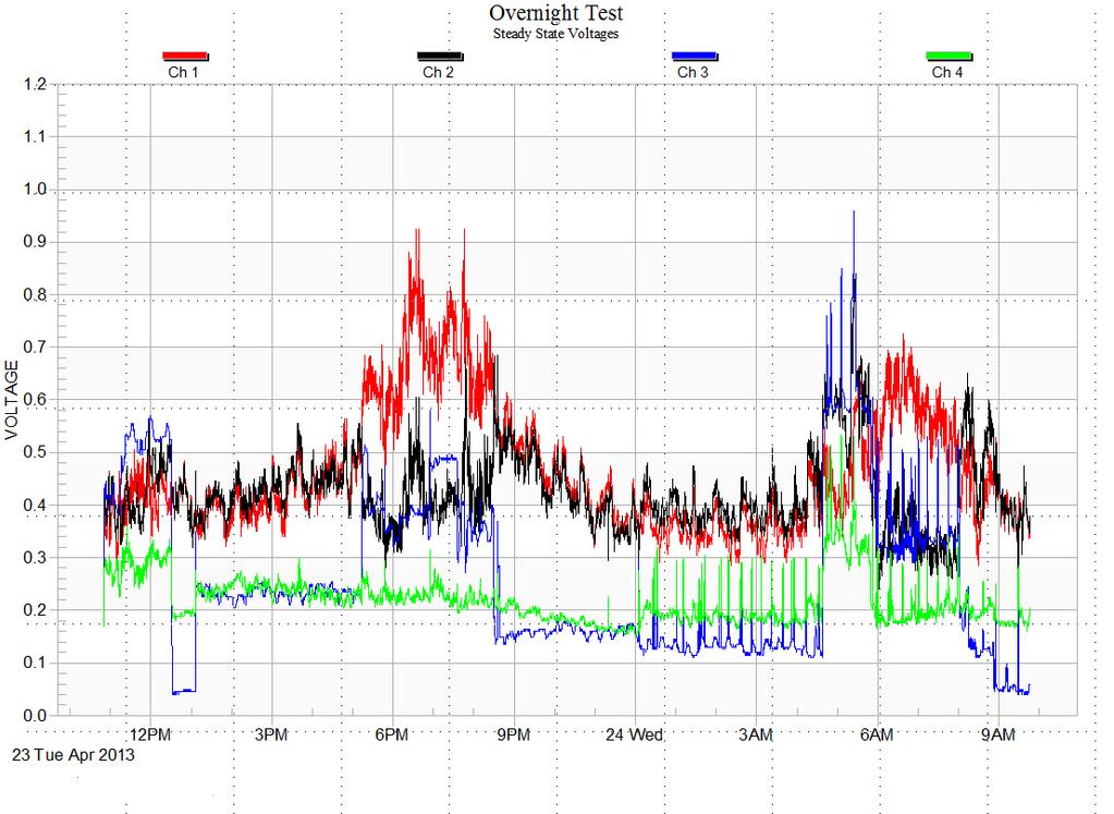
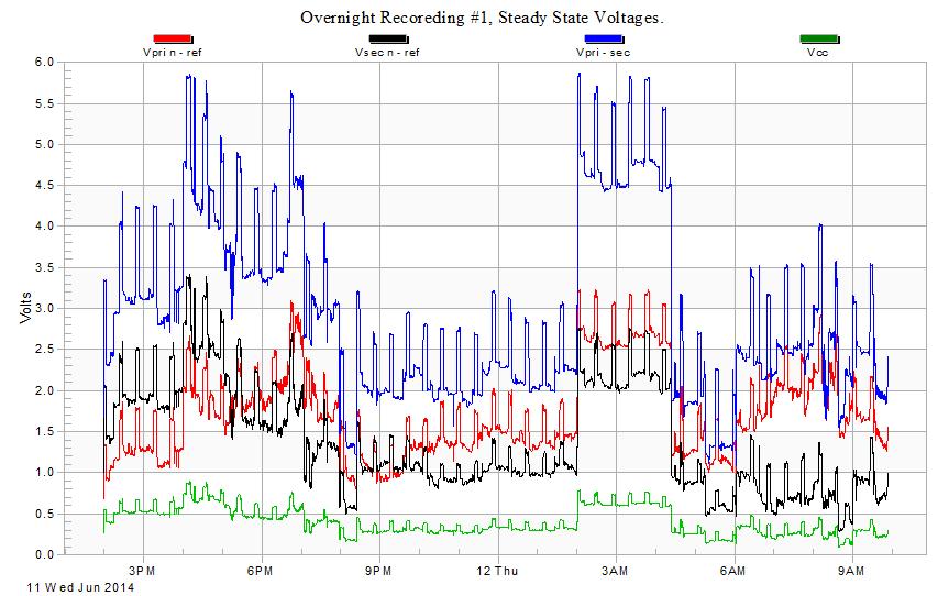
How to distinguish the contributions of Vp and Vps.
|
|
|
- Milo Montgomery
- 5 years ago
- Views:
Transcription
1 How to distinguish the contributions of Vp and Vps.

2
3
4
5 Load Box Test Current is injected at this point in the circuit (at the transformer) by a load box load, and measured on all of the paths leaving the transformer.
6
7
8 Test Load
9
10
11 0.75 Volts 3.5 Volts 0.8 Volts 2.8 Volts
12 K (Vps) = 21 % K(Vp) = 26%
13 Example
14
15
16
17 From the Load Box Test Rt = 0.23 Ohms Rf = 0.93 Ohms Rp = 0.32 Ohms K = 28 % ΔCR =74%
18 From V-Drop Test 0.25 Volts 12.8 A 0.05 Volts 0.02 Volts K(Vps) = 20% 0.2 Volts
19
20 K (Vps) = 20% K(Vp) = 28% x 0.20 (Vps) = 0.11 Volts 1.7 x 0.28 (Vs) = 0.48 Volts 0.48 V V = 0.37 Volts Vcc max measured = Volts
21 Example
22
23
24
25 From the Load Box Test Rt = 0.18 Ohms Rf = 0.97 Ohms Rp = 0.25 Ohms K = 21 % ΔCR =90%
26 From V-Drop Test 3.75 Volts 11.5 A 0.56 Volts 1.62 Volts K(Vps) = 15% 2.16 Volts
27
28 K (Vps) = 15% K(Vp) = 21% 5.8 x 0.15 (Vps) = 0.87 Volts 2.5 x 0.21 (Vp) = 0.53 Volts 0.87 V V = 1.4 Volts But Vcc max measured = 0.91 Volts
29 Vps affecting Vp Vps Impact on Vp 43 % Thus Vps of 5.8 V impacts Vp by 2.5 V 2.5 V x 21% = V 0.53V = 0.97 V
30 After Connector Fixed
31
32
33
34 From the Load Box Test Rt = 0.16 Ohms Rf = 0.88 Ohms Rp = 0.20 Ohms K = 21 % ΔCR =80%
35 From V-Drop Test 0.35 Volts 12.6 A 0.09 Volts 0.07 Volts K(Vps) = 21% 0.26 Volts
36
37 K (Vps) = 26% K(Vp) = 21% 0.13 x 0.26 (Vps) = 0.03 Volts 1.24 x 0.21 (Vp) = 0.26 Volts 0.03 V V = 0.29 Volts Vcc max measured = 0.27 Volts
38
39
40
41
42
43 Example #2
44
45
46
47
48 From the Load Box Test Rt = 0.28 Ohms Rf = 1.68 Ohms Rp = 0.32 Ohms K = 38 % ΔCR =85%
49 From V-Drop Test 0.6 Volts 13.5 A 0.32 Volts 0.03 Volts 0.60 Volts
50 K (Vps) = 53 % K(Vp) = 38% 0.53 x 0.89 (Vps) = 0.47 Volts 0.38 x (Vp) = 0.64 Volts 0.47 V V = 1.11 Volts Vcc max measured = 1.22 Volts
51 From the Voltage Drop Test, almost all of the voltage drop between the transformer and the barn shows up as barn panel to reference rod voltage.
52 From the voltage drop test, a 13.5 Amp load generated a change of 0.32 Volts in the cow contact voltage. Thus a 0.89 Volt drop should generate a Vcc change of 0.89/0.6 x 0.32 = 0.47 Volts
53 0.38 (k factor) x 2.57 Volts (Vs) = 0.98 Volts Vps = 0.89 Volts 100 % of 0.89 Volts =.89 Volts 0.05 % of 0.89 Volts = 0.04 Volts Adjusted Vs without Voltage drop = 1.69 Volts. Adjusted Vp without Voltage drop = 1.69 Volts. Contribution from Vp = 1.69 x 0.38 = 0.64Volts From Vps, 0.89 x 38 % = 0.34 Volts = 0.98 Volts = 1.11 Volts
54 Example #3
55
56
57
58
59 From the Load Box Test Rt = 0.12 Ohms Rf = 6.82 Ohms Rp = 0.13 Ohms K = 51 % ΔCR =98%
60 From V-Drop Test 0.90 Volts 12.7 A 0.27 Volts 0.15 Volts 0.76 Volts
61 K (Vps) = 30 % K(Vp) = 51% 0.30 x 0.84 (Vps) = 0.25 Volts 0.51 x 0.41 (Vp) = 0.21 Volts 0.25 V V = 0.46 Volts Vcc max measured = 0.54 Volts
62 From the Voltage Drop Test, 85 % of the voltage drop between the transformer and the barn shows up as barn panel to reference rod voltage. And thus 15 % shows up at as a change in Vp.
63 From the voltage drop test, a 12.7 Amp load generated a Vdrop of 0.9 Volts and a change of 0.27 Volts in the cow contact voltage. Thus a 0.89 Volt drop should generate a Vcc change of about the same in the overnight recording.
64 0.51 (k factor) x 0.7 Volts (Vs) = 0.36 Volts Vps = 0.89 Volts 85 % of 0.89 Volts =.76 Volts 0.15 % of 0.89 Volts = 0.13 Volts Adjusted Vs without Voltage drop = Volts. Adjusted Vp without Voltage drop = Volts. Contribution from Vp = 0.41 X 0.51 = 0.21Volts From Vps, 0.71 x 51 % = 0.36 Volts
65 Example # 4
66
67
68
69
70 From the Load Box Test Rt = 0.18 Ohms Rf = 2.25 Ohms Rp = 0.22 Ohms K = 41 % ΔCR =82%
71 From V-Drop Test 0.76 Volts 12.9 A 0.32 Volts 0.06 Volts 0.67 Volts
72 K (Vps) = 42 % K(Vp) = 41% x 0.42 (Vps) = 0.59 Volts 0.22 x 0.41 (Vp) = 0.09 Volts 0.7 V V = 0.68 Volts Vcc max measured = 0.79 Volts
73 Example # 4A
74
75
76
77
78 From the Load Box Test Rt = 0.27 Ohms Rf = 7.2 Ohms Rp = 0.28 Ohms K = 48 % ΔCR =98%
79 From V-Drop Test 0.34 Volts 13.4 A 0.17 Volts 0.01 Volts 0.35 Volts
80 K (Vps) = 50 % K(Vp) = 48% 0.74 x 0.5 (Vps) = 0.37Volts x 0.48 (Vp) = 0.19 Volts 0.37 V V = 0.56 Volts Vcc max measured = Volts
81 Example # 5
82
83
84
85
86 From the Load Box Test Rt = 0.15 Ohms Rf = 1.5 Ohms Rp = 0.16 Ohms K = 30 % ΔCR =91%
87 From V-Drop Test 1.53 Volts A 0.40 Volts 0.3 Volts 1.3 Volts
88 K (Vps) = 26 % K(Vp) = 30% 1.66 x 0.26 (Vps) = 0.43Volts 0.57 x 0.30 (Vp) = 0.17 Volts 0.61 V V = 0.60 Volts Vcc max measured = 0.56 Volts
89 Example # 6
90
91
92
93
94 From the Load Box Test Rt = 0.23 Ohms Rf = 1.12 Ohms Rp = 0.27 Ohms K = 18 % ΔCR =83%
95 From V-Drop Test 0.32 Volts 13.7 A 0.06 Volts 0.06 Volts 0.17 Volts
96 K (Vps) = 30 % K(Vp) = 18% x 0.30 (Vps) = 0.02Volts 1.46 x 0.18 (Vp) = 0.26 Volts 0.26 V V = 0.28 Volts Vcc max measured = Volts
97 On Farm Source, Not Vps
98 Example # 7
99
100
101
102
103 From the Load Box Test Rt = 0.18 Ohms Rf = 0.97 Ohms Rp = 0.25 Ohms K = 21 % ΔCR =90%
104 From V-Drop Test 3.75 Volts 11.5 A 0.56 Volts 1.62 Volts 2.16 Volts
105 K (Vps) = 15% K(Vp) = 21% 5.8 x 0.15 (Vps) = 0.87 Volts 2.5 x 0.21 (Vp) = 0.53 Volts 0.87 V V = 1.4 Volts But Vcc max measured = 0.91 Volts
106 Vps affecting Vp Vps Impact on Vp 43 % Thus Vps of 5.8 V impacts Vp by 2.5 V 2.5 V x 21% = V 0.53V = 0.97 V
107 After Connector Fixed
108
109
110
111
112 From the Load Box Test Rt = 0.16 Ohms Rf = 0.88 Ohms Rp = 0.20 Ohms K = 21 % ΔCR =80%
113 From V-Drop Test 0.35 Volts 12.6 A 0.09 Volts 0.07 Volts 0.26 Volts
114 K (Vps) = 26% K(Vp) = 21% 0.13 x 0.26 (Vps) = 0.03 Volts 1.24 x 0.21 (Vp) = 0.26 Volts 0.03 V V = 0.29 Volts Vcc max measured = 0.27 Volts
115 Example #1
116
117
118
119 From the Load Box Test Rt = 0.03 Ohms Rf = 0.2 Ohms Rp = 0.05 Ohms K = 73 % ΔCR =82%
120 From V-Drop Test 0.23 Volts 13 Amps Volts 0.05 Volts 0.18 Volts
121 80 % shows up at the barn pnl 20 % show up at the primary neutral
122 K (Vps) = 59 % K(Vp) = 73% 0.59 x 0.33 (Vps) = 0.19 Volts 0.73 x (Vp) = 0.24 Volts 0.19 V V = 0.43 Volts Vcc max (as measured) = 0.42 Volts
123 Without the voltage drop, Vp would = Vs, and Vcc should be k x Vs (or Vp) So what is the contribution of Vp to the stray voltage levels at the time of highest Vcc?
124 0.73 (k factor) x 0.57 Volts (Vs) = 0.42 Volts Vps = 0.33 Volts 80 % of 0.33 Volts =.24 Volts 20 % of 0.33 Volts = 0.06 Volts Adjusted Vs without Voltage drop = 0.33 Volts. Adjusted Vp without Voltage drop = Volts. Contribution from Vp = Volts Vps x 0.24 x 73 % = 0.18 Volts = 0.42 Volts.
resistance in the circuit. When voltage and current values are known, apply Ohm s law to determine circuit resistance. R = E/I ( )
") DC Fundamentals Ohm s Law Exercise 1: Ohm s Law Circuit Resistance EXERCISE OBJECTIVE When you have completed this exercise, you will be able to determine resistance by using Ohm s law. You will verify
DC Fundamentals Ohm s Law Exercise 1: Ohm s Law Circuit Resistance EXERCISE OBJECTIVE When you have completed this exercise, you will be able to determine resistance by using Ohm s law. You will verify
0-2 Operations with Complex Numbers
 Simplify. 1. i 10 1 2. i 2 + i 8 0 3. i 3 + i 20 1 i esolutions Manual - Powered by Cognero Page 1 4. i 100 1 5. i 77 i 6. i 4 + i 12 2 7. i 5 + i 9 2i esolutions Manual - Powered by Cognero Page 2 8.
0-2 Operations with Complex Numbers
 Simplify. 1. i 10 2. i 2 + i 8 3. i 3 + i 20 4. i 100 5. i 77 esolutions Manual - Powered by Cognero Page 1 6. i 4 + i 12 7. i 5 + i 9 8. i 18 Simplify. 9. (3 + 2i) + ( 4 + 6i) 10. (7 4i) + (2 3i) 11.
3-3 Complex Numbers. Simplify. SOLUTION: 2. SOLUTION: 3. (4i)( 3i) SOLUTION: 4. SOLUTION: 5. SOLUTION: esolutions Manual - Powered by Cognero Page 1
( 3i) SOLUTION: 4. SOLUTION: 5. SOLUTION: esolutions Manual - Powered by Cognero Page 1") 1. Simplify. 2. 3. (4i)( 3i) 4. 5. esolutions Manual - Powered by Cognero Page 1 6. 7. Solve each equation. 8. Find the values of a and b that make each equation true. 9. 3a + (4b + 2)i = 9 6i Set the
1. Simplify. 2. 3. (4i)( 3i) 4. 5. esolutions Manual - Powered by Cognero Page 1 6. 7. Solve each equation. 8. Find the values of a and b that make each equation true. 9. 3a + (4b + 2)i = 9 6i Set the
What to Add Next time you update?
 What to Add Next time you update? Work sheet with 3 and 4 resistors Create worksheet of tables Add Hypothesis and Questions Add Lab and Lecture Objectives Add equipment needed Add science standards Review
Sirindhorn International Institute of Technology Thammasat University at Rangsit
 Sirindhorn International Institute of Technology Thammasat University at Rangsit School of Information, Computer and Communication Technology COURSE : ECS 304 Basic Electrical Engineering Lab INSTRUCTOR
Topic 4 Formula. Introduction: V = IR Write down the formula being used. V = (5)(10) Substitute I with 5 and R with 10
(10) Substitute I with 5 and R with 10") Topic 4 Formula Introduction: In many situations in science and business we use formulas. these formula are essentially just an algebraic expression where the variables used have very specific meanings.
Topic 4 Formula Introduction: In many situations in science and business we use formulas. these formula are essentially just an algebraic expression where the variables used have very specific meanings.
Fig. 1-1 Current Flow in a Resistive load
 1 Electric Circuits: Current flow in a resistive load flows either from (-) to () which is labeled below as Electron flow or the Conventional flow from () to (-). We will use conventional flow in this
Delta & Y Configurations, Principles of Superposition, Resistor Voltage Divider Designs
 BME/ISE 3511 Bioelectronics - Test Three Course Notes Fall 2016 Delta & Y Configurations, Principles of Superposition, esistor Voltage Divider Designs Use following techniques to solve for current through
Exercise 1: Thermistor Characteristics
 Exercise 1: Thermistor Characteristics EXERCISE OBJECTIVE When you have completed this exercise, you will be able to describe and demonstrate the characteristics of thermistors. DISCUSSION A thermistor
The per unit system is based on the formula shown in Equation (1).
.") TECHNCAL ULLETN 007 Overview The per unit system is based on the formula shown in Equation (1). (1) per unit actual quantity base quantity Using this method, all quantities are expressed as ratios of some
TECHNCAL ULLETN 007 Overview The per unit system is based on the formula shown in Equation (1). (1) per unit actual quantity base quantity Using this method, all quantities are expressed as ratios of some
2015 EdExcel A-Level Physics Topic 3. Charge and current
 2015 EdExcel A-Level Physics Topic 3 Charge and current 9/17/2018 Electric Charge Atoms consists of Negatively-charged electrons and Positively charged protons. Atoms have the same number of protons and
STEAM Clown Production. Series Circuits. STEAM Clown & Productions Copyright 2017 STEAM Clown. Page 2
 Production Series Circuits Page 2 Copyright 2017 Series Parallel Circuits + + SERIES CIRCUIT PARALLEL CIRCUIT Page 3 Copyright 2017 Trick to Remember Ohm s Law V V=I*R R = V I I R I = V R Page 4 Copyright
Lecture (5) Power Factor,threephase circuits, and Per Unit Calculations
 Power Factor,threephase circuits, and Per Unit Calculations") Lecture (5) Power Factor,threephase circuits, and Per Unit Calculations 5-1 Repeating the Example on Power Factor Correction (Given last Class) P? Q? S? Light Motor From source 1000 volts @ 60 Htz 10kW
Lecture (5) Power Factor,threephase circuits, and Per Unit Calculations 5-1 Repeating the Example on Power Factor Correction (Given last Class) P? Q? S? Light Motor From source 1000 volts @ 60 Htz 10kW
POE Practice Test - Electricity, Power, & Energy
 Class: Date: POE Practice Test - Electricity, Power, & Energy Multiple Choice Identify the choice that best completes the statement or answers the question. 1. Which of the following forms of energy is
Unit 2 Electrical Quantities and Ohm s Law
 Electrical Quantities and Ohm s Law Objectives: Define a coulomb. Define an ampere. Define a volt. Define an ohm. Define a watt. Objectives: Compute electrical values using Ohm s law. Discuss basic types
EE 321 Analog Electronics, Fall 2013 Homework #3 solution
 EE 32 Analog Electronics, Fall 203 Homework #3 solution 2.47. (a) Use superposition to show that the output of the circuit in Fig. P2.47 is given by + [ Rf v N + R f v N2 +... + R ] f v Nn R N R N2 R [
Name. Section. Short Answer Questions. 1. (20 Pts) 2. (10 Pts) 3. (5 Pts) 4. (10 Pts) 5. (10 Pts) Regular Questions. 6. (25 Pts) 7.
 2. (10 Pts) 3. (5 Pts) 4. (10 Pts) 5. (10 Pts) Regular Questions. 6. (25 Pts) 7.") Name Section Short Answer Questions 1. (20 Pts) 2. (10 Pts) 3. (5 Pts). (10 Pts) 5. (10 Pts) Regular Questions 6. (25 Pts) 7. (20 Pts) Notes: 1. Please read over all questions before you begin your work.
Name Section Short Answer Questions 1. (20 Pts) 2. (10 Pts) 3. (5 Pts). (10 Pts) 5. (10 Pts) Regular Questions 6. (25 Pts) 7. (20 Pts) Notes: 1. Please read over all questions before you begin your work.
ELECTRICITY. Electric Circuit. What do you already know about it? Do Smarty Demo 5/30/2010. Electric Current. Voltage? Resistance? Current?
 ELECTRICITY What do you already know about it? Voltage? Resistance? Current? Do Smarty Demo 1 Electric Circuit A path over which electrons travel, out through the negative terminal, through the conductor,
Review. Multiple Choice Identify the letter of the choice that best completes the statement or answers the question.
 Review Multiple Choice Identify the letter of the choice that best completes the statement or answers the question. 1. When more devices are added to a series circuit, the total circuit resistance: a.
Chapter 21 Electric Current and Circuits
 Chapter 21 Electric Current and Circuits 1 As an introduction to this chapter you should view the following movie. If you cannot click on the link, then copy it and paste it into your web browser. http://www.ionaphysics.org/movies/vir.mp4
Fundamentals of Electric Circuits, Second Edition - Alexander/Sadiku
 Chapter 3, Problem 9(8). Find V x in the network shown in Fig. 3.78. Figure 3.78 Chapter 3, Solution 9(8). Consider the circuit below. 2 Ω 2 Ω -j 8 30 o I j 4 j 4 I 2 -j2v For loop, 8 30 = (2 j4)i ji 2
Elevated Neutral to Earth Voltages Due to Harmonics A T&D Update
 Elevated Neutral to Earth Voltages Due to Harmonics A T&D Update E. R. (Randy) Collins, PhD, PE Dept. of Electrical and Computer Engineering Clemson University Clemson, South Carolina Stray Voltage Panel
What are the two types of current? The two types of current are direct current and alternating current.
 Electric Current What are the two types of current? The two types of current are direct current and alternating current. Electric Current The continuous flow of electric charge is an electric current.
BACKGROUND KNOWLEDGE for Teachers and Students
 Pathway: Mechanical Systems and Technology Lesson: AMT A4 3: Measuring and Calculating Electricity Common Core State Standards for Mathematics: 9-12.A-CED.1, 9-12.A-CED.4 Domain: Creating Equations A-CED
EE-201 Review Exam I. 1. The voltage Vx in the circuit below is: (1) 3V (2) 2V (3) -2V (4) 1V (5) -1V (6) None of above
 3V (2) 2V (3) -2V (4) 1V (5) -1V (6) None of above") EE-201, Review Probs Test 1 page-1 Spring 98 EE-201 Review Exam I Multiple Choice (5 points each, no partial credit.) 1. The voltage Vx in the circuit below is: (1) 3V (2) 2V (3) -2V (4) 1V (5) -1V (6)
EE-201, Review Probs Test 1 page-1 Spring 98 EE-201 Review Exam I Multiple Choice (5 points each, no partial credit.) 1. The voltage Vx in the circuit below is: (1) 3V (2) 2V (3) -2V (4) 1V (5) -1V (6)
CHAPTER 6 SIMPLE EQUATIONS
 CHAPTER 6 SIMPLE EQUATIONS EXERCISE 6, Page 5 1. Solve the equation: x + 5 = 7 Since x + 5 = 7 then x = 7 5 x = from which, x = = 1. Solve the equation: 8-3t = Since 8 3t = then 8 = 3t 6 = 3t from which,
JFET Homework. Nov. 4, 2007, rev. Nov. 12, 2015
 Nov. 4, 2007, rev. Nov. 12, 2015 These homework problems provide practice with analysis and design involving the most common type of JFET circuits. There is one problem for each type of circuit. Answers
Chapter 3 Static and Current Electricity
 Chapter 3 Static and Current Electricity 3.1 Static Electricity - the build up of an electronic charge on a body (object) Electroscope - a device for detecting (not measuring) static charge attraction/repulsion
US ARMY INTELLIGENCE CENTER CIRCUITS
 SUBCOURSE IT 0334 EDITION C US ARMY INTELLIGENCE CENTER CIRCUITS CIRCUITS Subcourse Number IT0334 EDITION C US ARMY INTELLIGENCE CENTER FORT HUACHUCA, AZ 85613-6000 4 Credit Hours Edition Date: December
Exercise 1: RC Time Constants
 Exercise 1: RC EXERCISE OBJECTIVE When you have completed this exercise, you will be able to determine the time constant of an RC circuit by using calculated and measured values. You will verify your results
E E 2320 Circuit Analysis. Calculating Resistance
 E E 30 Circuit Analysis Lecture 03 Simple esistive Circuits it and Applications Calculating esistance l A 6 1.67 10 cm cu 6 al.7010 Area, A When conductor has uniform crosssection cm l 1 Temperature Coefficient
Exercise 2: Bending Beam Load Cell
 Transducer Fundamentals The Strain Gauge Exercise 2: Bending Beam Load Cell EXERCISE OBJECTIVE When you have completed this exercise, you will be able to explain and demonstrate the operation of a board,
Electricity Review completed.notebook. June 13, 2013
 Which particle in an atom has no electric charge associated with it? a. proton c. neutron b. electron d. nucleus Jun 12 9:28 PM The electrons in a metal sphere can be made to move by touching it with a
Grade 6 Math Circles. Circuits
 Faculty of Mathematics Waterloo, Ontario NL 3G Electricity Grade 6 Math Circles March 8/9, 04 Circuits Centre for Education in Mathematics and Computing Electricity is a type of energy that deals with
mith College Computer Science CSC270 Spring 16 Circuits and Systems Lecture Notes Week 3 Dominique Thiébaut
 mith College Computer Science CSC270 Spring 16 Circuits and Systems Lecture Notes Week 3 Dominique Thiébaut dthiebaut@smith.edu Crash Course in Electricity and Electronics Zero Physics background expected!
Exercise 2: The DC Ohmmeter
 Exercise 2: The DC Ohmmeter EXERCISE OBJECTIVE When you have completed this exercise, you will be able to measure resistance by using a basic meter movement. You will verify ohmmeter operation by measuring
K&J Magnetics Mendocino Motor Worksheet
 K&J Magnetics Mendocino Motor Worksheet This report summarizes some theoretical work we did to answer these questions: What solar panels should we use? What gauge of magnet wire should we use? How many
EE301 RESISTANCE AND OHM S LAW
 Learning Objectives a. Describe the concept of resistance b. Use Ohm s law to calculate current, voltage, and resistance values in a circuit c. Discuss the difference between an open circuit and a short
Engineering Fundamentals and Problem Solving, 6e
 Engineering Fundamentals and Problem Solving, 6e Chapter 17 Electrical Circuits Chapter Objectives Compute the equivalent resistance of resistors in series and in parallel Apply Ohm s law to a resistive
Study Guide and Intervention
 Study Guide and Intervention Pure Imaginary Numbers A square root of a number n is a number whose square is n. For nonnegative real numbers a and b, ab = a b and a b = a, b 0. b The imaginary unit i is
B: Know Circuit Vocabulary: Multiple Choice Level 1 Prerequisites: None Points to: Know Circuit Vocabulary (Short Answer)
") B: Know Circuit Vocabulary: Multiple Choice Level 1 Prerequisites: None Points to: Know Circuit Vocabulary (Short Answer) Objectives: - Memorize the definitions of voltage, current resistance, and power.
B: Know Circuit Vocabulary: Multiple Choice Level 1 Prerequisites: None Points to: Know Circuit Vocabulary (Short Answer) Objectives: - Memorize the definitions of voltage, current resistance, and power.
Problem info Geometry model Labelled Objects Results Nonlinear dependencies
 Problem info Problem type: Transient Magnetics (integration time: 9.99999993922529E-09 s.) Geometry model class: Plane-Parallel Problem database file names: Problem: circuit.pbm Geometry: Circuit.mod Material
DC CIRCUIT ANALYSIS. Loop Equations
 All of the rules governing DC circuits that have been discussed so far can now be applied to analyze complex DC circuits. To apply these rules effectively, loop equations, node equations, and equivalent
Experiment #6. Thevenin Equivalent Circuits and Power Transfer
 Experiment #6 Thevenin Equivalent Circuits and Power Transfer Objective: In this lab you will confirm the equivalence between a complicated resistor circuit and its Thevenin equivalent. You will also learn
Electromagnetism Checklist
 Electromagnetism Checklist Elementary Charge and Conservation of Charge 4.1.1A Convert from elementary charge to charge in coulombs What is the charge in coulombs on an object with an elementary charge
Ohm's Law and Resistance
 Ohm's Law and Resistance Resistance Resistance is the property of a component which restricts the flow of electric current. Energy is used up as the voltage across the component drives the current through
8 TH GRADE MATHEMATICS:
 8 TH GRADE MATHEMATICS: AIM: USING OHM S LAW TO SOLVE MATH PROBLEMS HOME WORK: HANDOUT BY MR. AKOMAH ENCHANCING STUDENTS SKILLS IN INVERESE OPERATION USING OHMS LAW : Students will 1.Become aware of Ohm's
CIRCUITS AND ELECTRONICS. Dependent Sources and Amplifiers
 6.00 CIRCUITS AN ELECTRONICS ependent Sources and Amplifiers Review Nonlinear circuits can use the node method Small signal trick resulted in linear response Today ependent sources Amplifiers Reading:
Figure (13-1) Single Thermoelectric Couple where Th > Tc
 Single Thermoelectric Couple where Th > Tc") Technical Brief Basics on TEG Power Generation 13.0 Power Generation 13.1 Bismuth Telluride-based thermoelectric power modules are designed primarily for cooling or combined cooling and heating applications
Technical Brief Basics on TEG Power Generation 13.0 Power Generation 13.1 Bismuth Telluride-based thermoelectric power modules are designed primarily for cooling or combined cooling and heating applications
1. Mark the correct statement(s)
") 1. Mark the correct statement(s) Figure to the right shows a mass measurement scale using a spring. 1.1 The span of the scale is a) 16 kg b) 21 kg c) 11 kg d) 5-16 kg 1.2 The range of the scale is a) 16
1. Mark the correct statement(s) Figure to the right shows a mass measurement scale using a spring. 1.1 The span of the scale is a) 16 kg b) 21 kg c) 11 kg d) 5-16 kg 1.2 The range of the scale is a) 16
Name: Lab Partner: Section:
 Chapter 6 Capacitors and RC Circuits Name: Lab Partner: Section: 6.1 Purpose The purpose of this experiment is to investigate the physics of capacitors in circuits. The charging and discharging of a capacitor
DC motor / generator. Jeffrey A. Meunier
 DC motor / generator Jeffrey A. Meunier jeffm@engr.uconn.edu Electric motor An electric motor is used to convert electrical energy into mechanical energy. Electric motor An electric motor is used to convert
ENGG 1203 Tutorial_05. Use of Multimeter. Lab 5 : SYSTEM. Office hours : Chow Yei Ching, CB-LG205 Thu, Fri; 15:30-17:30
 ENGG 1203 Tutorial_05 Office hours : Chow Yei Ching, CB-LG205 Thu, Fri; 15:30-17:30 HW : -25%/day at least after 4 days, sample answer posted for study Lab 5 : Use of Multimeter The value showing is maximum
Electric Charges & Current. Chapter 12. Types of electric charge
 Electric Charges & Current Chapter 12 Types of electric charge Protons w/ + charge stuck in the nucleus Electrons w/ - charge freely moving around the nucleus in orbits 1 Conductors Allow the easy flow
Chapter 33 - Electric Fields and Potential. Chapter 34 - Electric Current
 Chapter 33 - Electric Fields and Potential Chapter 34 - Electric Current Electric Force acts through a field An electric field surrounds every electric charge. It exerts a force that causes electric charges
Greek Letter Omega Ω = Ohm (Volts per Ampere)
") ) What is electric current? Flow of Electric Charge 2) What is the unit we use for electric current? Amperes (Coulombs per Second) 3) What is electrical resistance? Resistance to Electric Current 4) What
) What is electric current? Flow of Electric Charge 2) What is the unit we use for electric current? Amperes (Coulombs per Second) 3) What is electrical resistance? Resistance to Electric Current 4) What
Chapter 18. Direct Current Circuits
 Chapter 18 Direct Current Circuits Sources of emf The source that maintains the current in a closed circuit is called a source of emf Any devices that increase the potential energy of charges circulating
ELECTRICITY & MAGNETISM CHAPTER 8
 ELECTRICITY & MAGNETISM CHAPTER 8 E & M - Focus Electric Charge & Force Magnetism Current, Voltage & Power Electromagnetism Simple Electrical Circuits Voltage & Current Transformation Electric Charge &
Electrostatics and Charge. Creating Electric Fields
 Electrostatics and Charge Creating Electric Fields Electric Charges Recall that all matter is made of atoms. Neutral atoms can acquire a charge in several different ways, all of which require movement
PHYSICS FORM 5 ELECTRICAL QUANTITES
 QUANTITY SYMBOL UNIT SYMBOL Current I Amperes A Voltage (P.D.) V Volts V Resistance R Ohm Ω Charge (electric) Q Coulomb C Power P Watt W Energy E Joule J Time T seconds s Quantity of a Charge, Q Q = It
Basic Electricity Video Exam
 Name: Class: Date: Basic Electricity Video Exam Multiple Choice Identify the choice that best completes the statement or answers the question. 1. Matter is made of. a. plasma, gas, and solid b. solid,
EXP. NO. 3 Power on (resistive inductive & capacitive) load Series connection
 load Series connection") OBJECT: To examine the power distribution on (R, L, C) series circuit. APPARATUS 1-signal function generator 2- Oscilloscope, A.V.O meter 3- Resisters & inductor &capacitor THEORY the following form for
OBJECT: To examine the power distribution on (R, L, C) series circuit. APPARATUS 1-signal function generator 2- Oscilloscope, A.V.O meter 3- Resisters & inductor &capacitor THEORY the following form for
Exploring Operations Involving Complex Numbers. (3 + 4x) (2 x) = 6 + ( 3x) + +
 (2 x) = 6 + ( 3x) + +") Name Class Date 11.2 Complex Numbers Essential Question: What is a complex number, and how can you add, subtract, and multiply complex numbers? Explore Exploring Operations Involving Complex Numbers In
Name Class Date 11.2 Complex Numbers Essential Question: What is a complex number, and how can you add, subtract, and multiply complex numbers? Explore Exploring Operations Involving Complex Numbers In
Three Terminal Regulators & Overvoltage Protection. Bill Leonard N0CU
 Three Terminal Regulators & Overvoltage Protection Bill Leonard N0CU Three Terminal Regulators 101 V IN IN 3 Term Reg ADJ OUT R1 V OUT (1.2-33V) Volt Adjust R2 Current & power dissipation limits vary with
Electron Theory of Charge. Electricity. 1. Matter is made of atoms. Refers to the generation of or the possession of electric charge.
 Electricity Refers to the generation of or the possession of electric charge. There are two kinds of electricity: 1. Static Electricity the electric charges are "still" or static 2. Current Electricity
Which of these particles has an electrical charge?
 Which of these particles has an electrical charge? A. Proton. B. Electron. C. Ion. D. All of the above. Which is the predominant carrier of charge in copper wire? A. Proton. B. Electron. C. Ion. D. All
Current Electricity.notebook. December 17, 2012
 1 Circuit Diagrams and Assembly 1. Draw a circuit diagram containing a battery, a single throw switch, and a light. 2. Once the diagram has been checked by your teacher, assemble the circuit. Keep the
Basic Electricity. ME 120 Lecture Notes. Portland State University Mechanical and Materials Engineering
 Basic Electricity ME 120 Lecture Notes Portland State University Mechanical and Materials Engineering Learning Objectives Successful completion of this module will enable students to Link the basic model
Coulomb s constant k = 9x10 9 N m 2 /C 2
 1 Part 2: Electric Potential 2.1: Potential (Voltage) & Potential Energy q 2 Potential Energy of Point Charges Symbol U mks units [Joules = J] q 1 r Two point charges share an electric potential energy
This addendum describes the use of new termination actions in the Arbitrary Control Experiment in FuelCell Version 3.8d and later.
 FuelCell Addendum Arbitrary Control Termination D. Johnson, Scribner Associates, Inc. 4/16/2007, Ver. 2 Introduction This addendum describes the use of new termination actions in the Arbitrary Control
WHAT ARE THE EFFECTS OF MOVING CHARGES?
 ELECTRICITY WHAT ARE THE EFFECTS OF MOVING CHARGES? ELECTRICAL CHARGES Most atoms have the same number of protons and electrons. They often lose and gain electrons. When this happens, the atom s charge
Unit 3 BLM Answers UNIT 3 BLM 3-46
 UNIT 3 BLM 3-46 Unit 3 BLM Answers BLM 3-3, Charge Transfer Diagrams 1. Positively charged objects should have more (+) than ( ). Negatively charged objects should have more ( ) than (+). 2. They must
Continuous flow of electric charges. Current Electricity
 Continuous flow of electric charges Current Electricity Did You Know? The voltage across a muscle cell in your body is about 70 millivolts. A millivolt (mv) is one thousandth of a volt. AC and DC DC Direct
320-amp-models.tex Page 1 ECE 320. Amplifier Models. ECE Linear Active Circuit Design
 320ampmodels.tex Page 1 ECE 320 Amplifier Models ECE 320 Linear Active Circuit Design 320ampmodels.tex Page 2 2Port Networks A 2port network is any circiut with two pairs of wires connecting to the outside
Switch or amplifies f. Capacitor i. Capacitance is measured in micro/pico farads ii. Filters frequencies iii. Stores electrical energy
 Applied Science Study Guide By Patton and Zahen 1. Relationships between Science and Technology a. Circuits are a relationship between Science and technology because the power within a current comes from
Notes on Electricity (Circuits)
") A circuit is defined to be a collection of energy-givers (batteries) and energy-takers (resistors, light bulbs, radios, etc.) that form a closed path (or complete path) through which electrical current
A circuit is defined to be a collection of energy-givers (batteries) and energy-takers (resistors, light bulbs, radios, etc.) that form a closed path (or complete path) through which electrical current
SNC1DI Unit Review: Static & Current Electricity
 SNC1DI Unit Review: Static & Current Electricity 1. Be able to recognize the definitions for the following terms: Friction Contact Induction Lightning Electrostatic Series Pithball electroscope Insulators
Current and Resistance
 Current and Resistance 1 Define the current. Understand the microscopic description of current. Discuss the rat at which the power transfer to a device in an electric current. 2 2-1 Electric current 2-2
EE 321 Analog Electronics, Fall 2013 Homework #8 solution
 EE 321 Analog Electronics, Fall 2013 Homework #8 solution 5.110. The following table summarizes some of the basic attributes of a number of BJTs of different types, operating as amplifiers under various
Chapter 2. Engr228 Circuit Analysis. Dr Curtis Nelson
 Chapter 2 Engr228 Circuit Analysis Dr Curtis Nelson Chapter 2 Objectives Understand symbols and behavior of the following circuit elements: Independent voltage and current sources; Dependent voltage and
Arduino Software: How long before my battery is dead?, version 2.4
 Arduino Software: How long before my battery is dead?, version 2.4 By R. G. Sparber Protected by Creative Commons. 1 When powering an Arduino from a battery, it can be useful to be able to monitor available
Operational Amplifiers
 Operational Amplifiers A Linear IC circuit Operational Amplifier (op-amp) An op-amp is a high-gain amplifier that has high input impedance and low output impedance. An ideal op-amp has infinite gain and
Section 1 Electric Charge and Force
 CHAPTER OUTLINE Section 1 Electric Charge and Force Key Idea questions > What are the different kinds of electric charge? > How do materials become charged when rubbed together? > What force is responsible
PICK UP: Papers & Calc. TURN IN: - (orange sheet if you did not yesterday) DO NOW: On a half-sheet, draw the schematic for the following circuit.
 DO NOW: On a half-sheet, draw the schematic for the following circuit.") PICK UP: Papers & Calc HW: U7-9 (green) Next Test: QUIZ TOMORROW Exam 7 on 3/28 TURN IN: - (orange sheet if you did not yesterday) DO NOW: On a half-sheet, draw the schematic for the following circuit.
PICK UP: Papers & Calc HW: U7-9 (green) Next Test: QUIZ TOMORROW Exam 7 on 3/28 TURN IN: - (orange sheet if you did not yesterday) DO NOW: On a half-sheet, draw the schematic for the following circuit.
Chapter 28. Direct Current Circuits
 Chapter 28 Direct Current Circuits Electromotive Force An electromotive force device, or emf device, is a source of constant potential. The emf describes the work done per unit charge and has units of
Ohm s Law is a formula used to calculate the relationship between voltage, current and resistance in an electrical circuit.
 Quantity What is Ohm s Law? Ohm s Law is a formula used to calculate the relationship between voltage, current and resistance in an electrical circuit. To students of electronics, Ohm s Law (E = IR) is
SMPS-12 SERVICE MANUAL V2.00. Eclipse Use Switching Power Supply. Copyright 2001, RF Technology
 SMPS- Eclipse Use Switching Power Supply SERVICE MANUAL V.00 Copyright 00, Contents A. General Description... B. Rear Panel Description Power output P D-sub connector... I/O P D-sub connector... C. Circuit
670 Intro Physics Notes: Electric Current and Circuits
 Name: Electric Current Date: / / 670 Intro Physics Notes: Electric Current and Circuits 1. Previously, we learned about static electricity. Static electricity deals with charges that are at rest. 2. Now
EE313 Fall 2013 Exam #1 (100 pts) Thursday, September 26, 2013 Name. 1) [6 pts] Convert the following time-domain circuit to the RMS Phasor Domain.
![EE313 Fall 2013 Exam #1 (100 pts) Thursday, September 26, 2013 Name. 1) [6 pts] Convert the following time-domain circuit to the RMS Phasor Domain.](/thumbs/95/123488230.jpg "EE313 Fall 2013 Exam #1 (100 pts) Thursday, September 26, 2013 Name. 1) [6 pts] Convert the following time-domain circuit to the RMS Phasor Domain.") Name If you have any questions ask them. Remember to include all units on your answers (V, A, etc). Clearly indicate your answers. All angles must be in the range 0 to +180 or 0 to 180 degrees. 1) [6 pts]
Name If you have any questions ask them. Remember to include all units on your answers (V, A, etc). Clearly indicate your answers. All angles must be in the range 0 to +180 or 0 to 180 degrees. 1) [6 pts]
Chapter 5 Solution P5.2-2, 3, 6 P5.3-3, 5, 8, 15 P5.4-3, 6, 8, 16 P5.5-2, 4, 6, 11 P5.6-2, 4, 9
 Chapter 5 Solution P5.2-2, 3, 6 P5.3-3, 5, 8, 15 P5.4-3, 6, 8, 16 P5.5-2, 4, 6, 11 P5.6-2, 4, 9 P 5.2-2 Consider the circuit of Figure P 5.2-2. Find i a by simplifying the circuit (using source transformations)
Notes: Ohm s Law and Electric Power
 Name: Date: / / 644 Intro Physics Notes: Ohm s Law and Electric Power Ohm s Law: Important Terms Term Symbol Units Definition 1. current I amps flow of electric charges through a conductor 2. voltage V
U1 is zero based because its noninverting terminal is connected to circuit common. Therefore, the circuit reference voltage is 0 V.
 When you have completed this exercise, you will be able to operate a zener-clamped op amp comparator circuit using dc and ac voltages. You will verify your results with an oscilloscope. U1 is zero based
Electrical Forces arise from particles in atoms.
 Electrostatics Electrical Forces arise from particles in atoms. The protons(+) in the nucleus attract the electrons and hold them in orbit Electrons(-)repel other electrons and protons repel other protons
FOCUS: Water Pollkon Prevention and Control
 FOCUS: Water Pollkon Prevention and Control Many industrial processes, such as wastewater treatment, require careful control of ph/orp... By THOMAS H. MARTIN Consulting Chemist Delta Chemicals & Equipment,
Electricity & Magnetism
 Electricity & Magnetism Unit 7 Recall that Atoms l Have neutrons, protons, and electrons. l Protons are positively charged l Electrons are negatively charged l Opposite charges attract l Same charges repel
Electricity & Magnetism. Unit 6
 Electricity & Magnetism Unit 6 Recall that Atoms l Have neutrons, protons, and electrons. l Protons are positively charged l Electrons are negatively charged l Opposite charges attract l Same charges repel
Electrical Machines and Energy Systems: Operating Principles (Part 2) SYED A Rizvi
 SYED A Rizvi") Electrical Machines and Energy Systems: Operating Principles (Part 2) SYED A Rizvi AC Machines Operating Principles: Synchronous Motor In synchronous motors, the stator of the motor has a rotating magnetic
Electrical Machines and Energy Systems: Operating Principles (Part 2) SYED A Rizvi AC Machines Operating Principles: Synchronous Motor In synchronous motors, the stator of the motor has a rotating magnetic
wave speed (metre/second, m/s) = frequency (hertz, Hz) x wavelength (metre, m)
 = frequency (hertz, Hz) x wavelength (metre, m)") Physics formulae: Unit P1 (GCSE Science ( Core Science )): The relationship between wave speed, frequency and wavelength: wave speed (metre/second, m/s) = frequency (hertz, Hz) x wavelength (metre, m)
Physics formulae: Unit P1 (GCSE Science ( Core Science )): The relationship between wave speed, frequency and wavelength: wave speed (metre/second, m/s) = frequency (hertz, Hz) x wavelength (metre, m)