ATMOSPHERIC DISTURBANCE MONITOR MAIN CIRCUIT BOARD V5
|
|
|
- Darrell Robbins
- 5 years ago
- Views:
Transcription
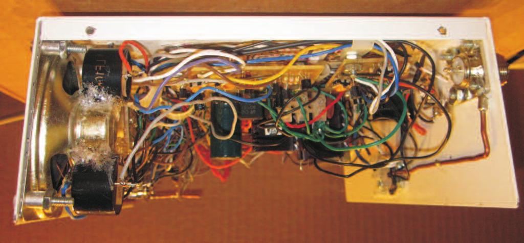
1 P VOL TMOSPHRI ISTURN MONITOR MIN IRUIT OR V5 R 70K IN 0mH 0pF OLLTOR OUT TST.00mF IN 70K mh Q R 0pF OLOR O: R 0mF N9 TRIM N9 K9. SI LIHTNIN TTOR (-) to (+) Pulse Out 5 00mF (+) to (-) Pulse Out 0R *R 0R R9 6 7mF 6 T 5V IN 5 P OUNTR *R PR VOLUM +5V FROM PULSS OLOR O: YN R N9 R0 K R 0M R K 7 70mF Q5 TRIM 0 to 00 mv Out. SVRITY MTR R 5V OLOR O: ROWN. L L ULTR- RIHT From Pulses. 5 V I OLOR O: ORN MO00 MP 6 5 0R MT 5V Q6 00V 6 MT TRI 5V MTR LS ML-ML STRW HT OOL WHIT L.FV 0-00 mv from Meter kt. +5V R R9 70K TRIM 50K PRST JUST R0 0M I LM9 5. PRST LVL R K (0) R Q7 N7000 S + OLOR O: OL 7 SIRN LO XX OUT 00m MX 0R 5 P Z 6. P Q7: N-hnnel nhncement Moe Fiel ffect Trnsistor STS FULL ON/OFF STT ntenn IN 0mH I MO00 R 70K 0pF 5V IN (TRI) 0R P ounter XX LNNI ZINK 5V Q LIHTNIN TTOR V5 5V OUT (TRI) 0R Pulse(+) HRLS WNZL 6 µ7f 70K *R 0R R9 0.00µF IN mh TST MT MT te TST *R PR VOLUM R 5 00µF R SIRN K TRIM R0 50K 0M PRST Q6 00V 6 R TRI K (0) I LM9 R9 5 70K 7 Q7 L S 70µF N7000 R etector 6 R TRIM R0 K K TRIM N9 (-)Pulse 0pF in (Mtr j) 0µF K9 N9 N9 S STTION TTOR OR PRTS LYOUT R 0M Q5 R L PRST R XX 5V LNNI ZINK Q P VOL S STTION TTOR OR OTTOM VIW LIHTNIN TTOR V5 HRLS WNZL
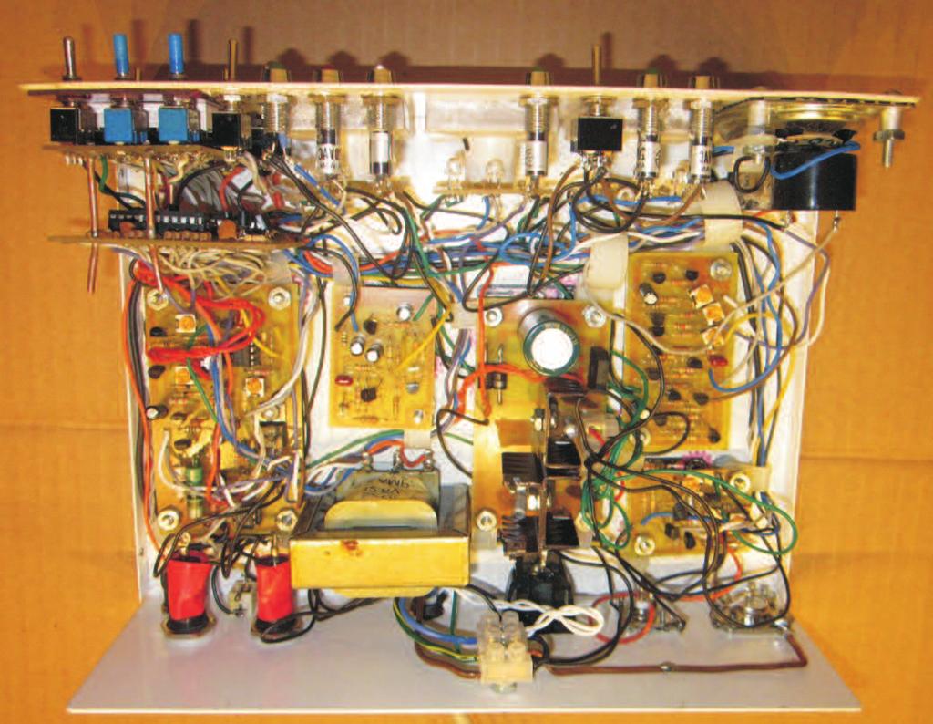
2 IIT OUNTR V IIT OUNTR V TMOSPHRI ISTURN MONITOR ONNTIONS to 5++6 b +0+5 c e f g ++ RST 0nF (0.0) f 5 e 9 F S 5 b c S S ISPLY OR PRTS LYOUT ebounce ircuit R 70K 5 6 I 09 I NOT US OUNT 0nF (0.0) g 9 LNNI ZINK I 09 I Note: W soli wire is solere to the isply bor extening out the bck fr enough to piggy-bck the compnion circuit bor. Slightly lrger holes llow bor to be remove. Soler is pplie to wire t stop points. Hlf-inch tils re slightly bent to keep bor in plce yet llow removl. to 5++6 b +0+5 c e f g ++ -IIT L ISPLY OMMON THO LT-5RI LUMX IIKY 67-5-N N RRY RST LOK LTH nf (.00) 6 b c I 0 5 e 9 f g S I S 55 S R R R f 7 THR IIT OUNTR V e, 6 om g c b 5 0 f b 0 g e c 6 9 om 7 6 f b 7 5 g e c 0 om F R9 R0 R 09 5V FROM PULSS R F R 70K F + N ommon Test 0nF (O.O) f g 5 -R c b I e 9 0n (0.0) R 70K LNNI ZINK Reset IIT OUNTR V LNNI ZINK Reset F + ommon Test IIT OUNTR V LNNI ZINK.mF I 09 7 R nf I 55 R 9 6 ISPLY OR OTTOM VIW LOI OR PRTS LYOUT LOI OR OTTOM VIW
3 SOP V - 7 LNNI ZINK Z TMOSPHRI ISTURN MONITOR PIZZ PN NTNN + MTL S R 0M N N9 S M 0-00m N9 R VR 50K ZRO S VR 5K LN LTROSOP V7 L 560K M7 90R L VR 5K LN N + R 0M NT N9 S R VR 50K ZRO N9 S M7 560K 90R PRTS LYOUT - SOP V 7 Z LNNI ZINK OTTOM VIW
4 LNNI ZINK STORM SIRN V TMOSPHRI ISTURN MONITOR 7mF 560K mf R0 0R XX 7 SIRN R R OPTIONL 0K 0pF K R R9 5 00mF R 00R SPK ohm MRNY SIRN SIMULTOR simple n fntstic circuit! Opertion is smooth n cn be triggere with low voltge. When switche off, the siren souns until it reches its low frequency cut off. The ecy is long so it tkes while! Originl version (Wenzel) wile when powere on. This feture ws not esirble for this project. R R R0 0R 7mF 560K mf R R9 00mF 00R 5 LNNI ZINK STORM SIRN V 0pF 0K R K PRTS LYOUT OTTOM VIW
5 TMOSPHRI ISTURN MONITOR W TTOR Q5 R Q7 R9 5K Q9 R0 LRM FLSHR VR R LK R 0R 60K * mf R * 0.mF *, SUPPRSSS 60Hz NOIS IN LON LS VR0 VR9 INTNSITY R 0R Q6 R R TTOR MOISTUR TTOR MTR WITH LRM V0 R Q 9 PT LRM F R 7K R 70K R 0 R 7mF Q5 R mf Q7 R 7mF R9 Q 5K 0 R R R 0R R R0 60K 70K Q9 Q6 R VR 0R VR0 5 R R R F R 7K VR9 (0) Z MTR W LNNI ZINK RN SNSOR TTOR V0 W MTR /SNSOR UZZR/ PRTS LYOUT LNNI ZINK W RN MTR TTOR V0 OTTOM VIW
6 +V LNNI ZINK +V ++V KUP SUPPLY TTRY OUL POWR - V TMOSPHRI ISTURN MONITOR 0V VT. ( VOLTS OVR HIHST OUTPUT) POWR TRMINL RRL POWR PLU S N5 00-0,000µF 5-50V S N µF 5V POWR SUPPLY WITH TTRY KUP WIR O: 709 5V +5V + 0.µF 0µF 5V 5 0.µF RUNS HOT. XTR HT SINK 0µF 5v 0.µF O I 0µF 5v ++V +V OUL POWR SUPPLY TTRY KUP LNNI ZINK S N5 UT O I +V UT FOR TTRY KUP US 0.µF - V UT S N5 00mF 5-50V OMPONNT LYOUT OTTOM VIW

7 TMOSPHRI ISTURN MONITOR

8 TMOSPHRI ISTURN MONITOR

9 TMOSPHRI ISTURN MONITOR
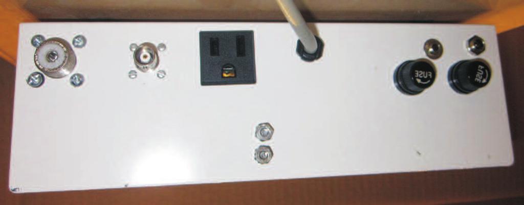
10 LTRIL ISHR NTNN TMOSPHRI HR NTNN TRI ONTROLL 5 V LIN OR TRNSFORMR FUS FUS SNSOR TRI FUS FUS VOLT TTRY TMOSPHRI ISTURN MONITOR OUNT RST TST HR tmospheric lectricl ischrge PRST WRNIN 9 W TMOSPHRI HR ISHR SVRITY W INTNSITY P 5 OUNT T SIRN 6 7 POWR tmospheric Monitor isturbnce with ttery ckup HOY LTRONIS, IN. POWR n P switches were swppe when upgre to bttery bckup. Upte LYOUT Lbel
11 LTRIL ISHR NTNN TMOSPHRI HR NTNN TRI ONTROLL TRNSFORMR FUS TRI FUS 5 V LIN OR SNSOR VOLT TTRY TMOSPHRI ISTURN MONITOR OUNT RST TST HR tmospheric lectricl ischrge PRST WRNIN W P OUNT T SIRN POWR tmospheric Monitor isturbnce with ttery ckup HOY LTRONIS, IN. POWR n P switches were swppe when upgre to bttery bckup. Upte Lbel
PROMOTES EXPERIMENTATION AND EXPLORATION
 Updated: 0- UIO & V POWR TO ORI / TRO / MONO PL N PL TRO JK UIO TH (MF/harge/Light/udio/Induction/RF/ferics) PROMOT XPRIMNTTION N XPLORTION 00pF R K MONO JK 0.µF 0µ F V 0M N.0µF LL-N 0M N0 WNZL UIO PUT
SEE PAGE 2 FOR BRUSH MOTOR WIRING SEE PAGE 3 FOR MANUFACTURER SPECIFIC BLDC MOTOR WIRING EXAMPLES EZ SERVO EZSV17 WIRING DIAGRAM FOR BLDC MOTOR
 0V TO 0V SUPPLY GROUN +0V TO +0V RS85 ONVRTR 9 TO OM PORT ON P TO P OM PORT US 9600 U 8IT, NO PRITY, STOP, NO FLOW TRL. OPTO SNSOR # GROUN +0V TO +0V GROUN RS85 RS85 OPTO SNSOR # PHOTO TRNSISTOR TO OTHR
SEE PAGE 2 FOR BRUSH MOTOR WIRING SEE PAGE 3 FOR MANUFACTURER SPECIFIC BLDC MOTOR WIRING EXAMPLES A
 7V TO 0V SUPPLY +7V TO +0V RS85 ONVRTR TO P OM PORT OR US US 9600 U 8IT, NO PRITY, STOP, NO FLOW TRL. 9 TO OM PORT ON P TO OTHR Z SRVOS OR Z STPPRS OPTO SNSOR # OPTO SNSOR # PHOTO TRNSISTOR OPTO SNSOR
 WIR OLOR O: K - LK R - ROWN - RK LU G - RK GRN GY - GRY L - LIGHT LU LG - LIGHT GRN OR - ORNG PK - PINK R - R YL - YLLOW VT - VIO WT - WHIT NOTS: ) LL ONNTORS R SHOWN IN TH LO POSITION. ) SPIL USTOMR OPTIONS
section 6 wiring diagrams
 section wiring diagrams W KOHLR TO HLIHT TO NUTRL SWITH ISTRIUTION LOK TO INITION SWITH US HOLR / / O RROW / / O RROW VIW - / / RTIIR / / STRTR SOLNOI OIL SNSOR NIN STOP ROUN ( ) POWR OUTLTS HLIHT SWITH
F102 1/4 AMP +240 VDC SEE FIGURE 5-14 FILAMENT AND OVEN CKTS BLU J811 BREAK-IN TB103 TO S103 TRANSMITTER ASSOCIATED CAL OFF FUNCTION NOTE 2 STANDBY
 OWR OR F0 M NOT S0 RT OF FUNTI FL0 T0 OWR SULY SUSSIS T0 T0 WIR FOR 0 V OWR SULY SUSSIS T0 WIR FOR V 0 0 RT V0 RT V0. V RT V0 RT V0 NOT. V. V NOT +0 V 0 +0 V. V 0 FUNTI NOT L +0 V S FIUR - FILMNT N OVN
135-91G00N ONE-WAY CUSTOMER UNIT FOR VAT 30GX AND Easy-aire 10GX
 ON-WY TV SYSTM OR VT GX UNITS L92 LL -8-999-6 -GN ON-WY USTOMR UNIT OR VT 2GX ND VT 2GX " (8. mm) OLOR D MR IN N NVIRONMNTLLY ONTROLLD HOUSING DIMNSIONS IN MILLIMTRS (DIMNSIONS IN T-INHS) -9GN ON-WY USTOMR
Q11 Q12 BF423 BF422 BF422 Q5 BC184L R39 5K6 Q15 BF422 R59 39K C28 C30 100UF 100NF R40 1K5 C23 100NF R38 R36 220K Q13 BF422 Q14 BF423 R71 47R
 R R HT+ 0 00N/ 00V R 0R R K R 0R R9 K GT RSISTORS R - R LT+ 00U MP R 0P R 00N/ R0 R Q R 0K Q VR 0R Q Q R 0R R R Q Q9 R R R K R R R 0R Q Q Q0 R R9 Q R R R R Z V Z V R K 00U/ V 00U V 9 00U/ V R0 / Q R 00N
INTLT W INTERIOR LIGHT DISCONNECT OPTION CUSTOMER LINE CONNECTION DISC SW PCB L1 L2 4L1 SEE MODBUS COMMUNICATION OPTION CI/HL DIG IN RS485 SCR RLY4
 LINE 0VPH0/0HZ OR L L L L S LIST LIST OF MTERIL J FU FU FU FU H H HETER R R R R H H L F L SPE LU TERMINLS 0. WHT T T LU T T MTR ORN T T T T LK JP T T YEL MOTOR TERMINLS P OFF ON INTERIOR LIHT 0 INTLT W
MATC DIGITAL ELECTRONICS LAB ASYNCHRONOUS RIPPLE COUNTERS
 MT IGITL ELETONIS L SYNHONOUS IPPLE OUNTES Submitted to: Mr. Pham Submitted by: Jody ecker Submitted on: //00 Performed on: //00 Lab Group # OJETIVES Jody ecker Elctec 0-00 Lab synchronous ounters Page
 Page of 5 Service Manual: SYSTM WIRIN IRMS POWR ISTRIUTI 003 hevrolet Monte arlo 3.8L ng SS ig : Power istribution ircuit ( of 5) USIL (0 -RUST) USIL (6 -LK) (W/NTI-LOK RKS SYSTM) USIL (8 -LU) STRTR MOR
LIVING/DINING 23'-6" x 13'-1" W/D M&E METER CLOSET OPT. PANTRY W/D. LIVING/DINING 23'-6" x 13'-1" ROOF TOP TERRACE AREA SQ. FT.
 NTRY NTRY '-3" x 8'-0" '-3" x 8'-0" ###### x 8'-3" / 23'-" x 3'-" NTRY NTRY 3'-" x 7'-0" 9'-7" x 9'-7" '-0" x '-9" RKST NOOK 9'-0" x '-" 0 0 0 LVTIONS N TILS ON 9 SRIS. SHUL N TILS ON 9 SRIS. '-3" x 8'-0"
 http://www.prodemand.com/print/index?content=tabs&module=true&tab=true&terms=tru... Page of //0 Toyota valon.0l ng XLS Service Manual: SYSTM WIRING IGRMS Print ate: //0 PRFORMN >.0L Fig :.0L, ngine Performance
 http://www.prodemand.com/print/index?content=tabs&module=true&tab=true&terms=tr... Page of //0 Service anual: SYST WIRING IGRS - G00 IR ONITIONING 0 hevrolet xpress.l ng G00 ig : anual / ircuit, argo Van
Service Information. Service. Service. Service FW-V220. Product Service Group CE Audio A02-160
 Service Service Service W-V0 0-0 Product Service Group udio Service Information lready published Service Informations: ORRTION TO SRVI MNUL elow are corrections to the circuit diagram parts list: OMI OR
CONNECTOR SYMBOL A SPLICE WIRE GAUGE CHART:
 RWING INX ONNTOR LOING IGRMS...--5--- ONNTOR LOTING IGRM...9 POWR ISTRIUTION...0- GROUN ISTRIUTION... SWITHS...-5 WIPR SYSTM... ORWR LMP WIRING... RR LIGHT WIRING-STNR...-9 LRN LIGHT SYSTM...0 RONT LRN
 H NT Z N RT L 0 4 n f lt r h v d lt n r n, h p l," "Fl d nd fl d " ( n l d n l tr l t nt r t t n t nt t nt n fr n nl, th t l n r tr t nt. r d n f d rd n t th nd r nt r d t n th t th n r lth h v b n f
160 SSC Variable Speed Drive (Series C)
") 0 SS Variable Speed rive (Series ) Publication 0-P onfigured rive Package Important User Information Solid state equipment has operational characteristics differing from those of electromechanical equipment.
0 SS Variable Speed rive (Series ) Publication 0-P onfigured rive Package Important User Information Solid state equipment has operational characteristics differing from those of electromechanical equipment.
NHT Pro. A20 Digital Meter. From Low. Voltage 3 R814. Power 3. Supply. From Left Power Amp. From. Rigjht 2. Amp R810 4.
 igital Meter R0.K V 0 0.UF U0 R 0 V R0 K 0 0.uF 0.V R9 R K K V V V 0 09 0 N0 0UF/V Low 0UF/V 00UF/V R R 00K 00K 0 pf Left N0 0 N N 0 VR0 0K 0 0.uF R 0M 0 0.uF k U0 9 0 V0 0.uF N0 V PI 0 09 R R 0 SPL GREEN
3V3 DECOUPLING DS90LV018A MCLKTON 4U7/10V +/-10% C196 +/-10% LCLK1IN+ NMCLKTON SK18 74LS123 MULTI +/-5% C N C94 10N
 0 THIS RWG ONORMS TO.S. -T-0-00-0- U/0V +/-% 00N +/-0% 0N +/-0% U/0V +/-% 00N +/-0% 0 0N +/-0% R R 0R % P/0V +/-% K % U S YLLOW U 0 U U S0LV0 MLKTON /R S S R SK LS MULTI U/0V +/-% 00N +/-0% 0N +/-0% LLK+
 D t r l f r th n t d t t pr p r d b th t ff f th l t tt n N tr t n nd H n N d, n t d t t n t. n t d t t. h n t n :.. vt. Pr nt. ff.,. http://hdl.handle.net/2027/uiug.30112023368936 P bl D n, l d t z d
3-Way Mixing and Sequencing Globe Valves, Flared (5/8 in. O.D.) with Electric, Hydraulic, and Pneumatic Actuators
 with Electric, Hydraulic, and Pneumatic Actuators") lectric, Hydrulic, nd Pneumtic ctutors TL 1. Select Vlve ody including P ode (Vlve Size, v Rting, Port ode) or select Vlve ssemly correct (refer to Tle 3 nd Tle 3 lso) less ctutor ode (XXX) including the
lectric, Hydrulic, nd Pneumtic ctutors TL 1. Select Vlve ody including P ode (Vlve Size, v Rting, Port ode) or select Vlve ssemly correct (refer to Tle 3 nd Tle 3 lso) less ctutor ode (XXX) including the
Amphenol Canada Corp.
 HT SINK OPTION = PIN STYL HT SINK (NIKL PLT) N LIP (H=.mm; SN HIGHT) = PIN STYL HT SINK (NIKL PLT) N LIP (H=.mm; PI HIGHT) = PIN STYL HT SINK (NIKL PLT) N LIP (H=.mm; TLL) = PIN-FIN HT SINK (NOIZ, LK)N
EE1000 Project 4 Digital Volt Meter
 Ovrviw EE1000 Projt 4 Diitl Volt Mtr In this projt, w mk vi tht n msur volts in th rn o 0 to 4 Volts with on iit o ury. Th input is n nlo volt n th output is sinl 7-smnt iit tht tlls us wht tht input s
J400 C UF,50V,20% V-STBY 10.0K,1%,1/4W R63 R61 1M,5%,1/4W V-STBY R K,1%,1/4W AC-OK RY3A R11INT 1 NC NO COM 47K,5%,1/4W R11
 MNL-PIN J MNL-PIN J MNL-PIN J MNL-PIN J J00-00 MNL-PIN J MV J MNL-PIN PHS-REF (Sh. ) IN-RET (Sh.,) -OK (Sh. ) HOT-IN 0V(US) 00V(INT) MV LIN-XFER (Sh. ) +V OOST (Sh. ) TRIM (Sh. ) MNL-PIN MNL-PIN 0V(US)
1) Actual pressure drop required for each metering land, up to the specified maximum flow rate is: Q ΔP actual. ) 2 PSI; (Q in GPM) actual Q rated
 Actual pressure drop required for each metering land, up to the specified maximum flow rate is: Q ΔP actual. ) 2 PSI; (Q in GPM) actual Q rated") tlog HY14-255/US echnicl Informtion Generl escription proportionl directionl control vlves re high performnce, two stge pilot operted solenoid vlves with electronic spool position feedck, nd on-ord integrted
tlog HY14-255/US echnicl Informtion Generl escription proportionl directionl control vlves re high performnce, two stge pilot operted solenoid vlves with electronic spool position feedck, nd on-ord integrted
+18VL. 220uf 25V. 0.1u C10UF. 100k AGND LEFT_OUT_+VE R19 22R -18VL. C9 150pF +18VL LEFT_OUT_-VE R uf 25V 22R
 RVIION ROR O NO: PPROV: T: VL LFT_IN_V Pt Q 0 Q R Q 0 R Q 0nf Q 0 N W R 0 00 0k Pt R 00 R R k R W R 00 0 00u W 00pf u R 00k N Q J u 0 Q Q 0 0.u 0UF 0uf V R 00k N R R LFT_OUT_V Notes: Use either Q/Q or
1K21 LED GR N +33V 604R VR? 1K0 -33V -33V 0R0 MUTE SWTH? JA? T1 T2 RL? +33V 100R A17 CB? 1N N RB? 2K0 QBI? OU T JE182 4K75 RB? 1N914 D?
 L P.O. O X 0, N L R. PROROUH, ONRIO N KJ Y PHO N (0) FX (0) 0 WWW.RYSON. ate : Size : 000 File : OVRLL SHMI.Schoc Sheet : 0 of 0 Rev : rawn : 0.0 0K K 0K K 0K0 0K0 0K0 0K0 0K0 00K R K0 R K 0R??? 00N M?
8-3/8" G HANDHOLE C A 1 SUCTION STEEL BASE TABLE OF DIMENSIONS
 VORTX SOLIS-NLIN WSTWTR S K OUR " N ONNTIONS OUR " I. OLS OR NOR OLTS -/" STION 0 OUTLIN RWIN TYP VTX- JO: SS-7 T VTX- VORTX (S) OR _PM T _T. T J PPX. N OVRLL L M PLN VIW PPX. P OVRLL 8-/8" P ISR OUPLIN
 ---------------------------------------------------------------------------------------------------------- PHYS 2326 University Physics II Class number ---------------------------------------------------------------------------------------------------------------------
DESIGN REVIEW BOARD Staff Report
 SIGN RVIW OR Staff Report genda Item F. Meeting ate: March, 0 TO: Goleta esign Review oard FROM: rian Hiefield, ssistant Planner; 9-9 SUJT: -0-R; ourtyard by Marriott Overall Sign Plan 0 Storke Road; PN
FEATURES. Tolerance. Value 2020 = +/- 20% 3030 = +/- 30% (See note 5) (See note 4) Taper. A = Linear B = Log. C = Alog.
 (See note 4) Taper. A = Linear B = Log. C = Alog.") Bushless version MHNIL SPIFITIONS Mechanical rotation angle: 300 ± lectrical rotation angle: ± Torque: 0. to. Ncm. (0.7 to 2. in-oz) Stop torque: > 0 Ncm. ( > in-oz) Max. torque nut (binding out): < 0
Bushless version MHNIL SPIFITIONS Mechanical rotation angle: 300 ± lectrical rotation angle: ± Torque: 0. to. Ncm. (0.7 to 2. in-oz) Stop torque: > 0 Ncm. ( > in-oz) Max. torque nut (binding out): < 0
P/N A042C868 TB-311 TB V +10V +10V LED 59 K23 +10V LED 60 LED 58 LED 47 K15 U18(P2) U14(P1) U18(P0) U18(P1) +10V +10V +10V LED 15 LED 18
 U14(P1) U18(P0) U18(P1) +10V +10V +10V LED 15 LED 18") P/N 0 P/N 0H0 TO PUMP ONTROLLER T- T- T- FPDP GEN II S P/N 0G SS P/N 0G P/N 0G ORD LED U(PIN) T- LED T- T- T- T- T- T-0 T-0 T-0 T-0 T-0 T-0 T- T- T-0 T-0 K U(P) T-0 LED U(P0) LED K U(P) LED K U(P) LED
P/N 0 P/N 0H0 TO PUMP ONTROLLER T- T- T- FPDP GEN II S P/N 0G SS P/N 0G P/N 0G ORD LED U(PIN) T- LED T- T- T- T- T- T-0 T-0 T-0 T-0 T-0 T-0 T- T- T-0 T-0 K U(P) T-0 LED U(P0) LED K U(P) LED K U(P) LED
828.^ 2 F r, Br n, nd t h. n, v n lth h th n l nd h d n r d t n v l l n th f v r x t p th l ft. n ll n n n f lt ll th t p n nt r f d pp nt nt nd, th t
 2Â F b. Th h ph rd l nd r. l X. TH H PH RD L ND R. L X. F r, Br n, nd t h. B th ttr h ph rd. n th l f p t r l l nd, t t d t, n n t n, nt r rl r th n th n r l t f th f th th r l, nd d r b t t f nn r r pr
TCI SERIES, 3 CELL THE COOLING TOWER CO., L.C. TCI 3 CELL SERIES GA
 of T SIN IS T PROPRTY O T OOLIN TOWR OMPNY, L, N IS LON OR MUTUL SSISTN. IT IS NOT TO ORWR NOR RPRINT IN NY ORM WITOUT WRITTN PRMISSION. L W OPTIONL SS PLTORM " x " STNR PLTORM PR LL OPTIONL VIRTION SWIT
KEB INVERTER L1 L2 L3 FLC - RELAY 1 COMMON I1 - APPROACH CLOSE 0V - DIGITAL COMMON FLA - RELAY 1 N.O. AN1+ - ANALOG 1 (+) CRF - +10V OUTPUT
 CRF - +10V OUTPUT") XT SSMLY MOL 00 (O FS) 00 (I- PT) 00 (SIGL SLI) WG O 0 0-0 0-0-0 0.0. 0 0-0 0-0-0 0 0-0 0-0-0 VOLTG F.L...0..0..0.0..0 IIG POW FOM US SUPPLI ISOT (S TL) US OP OUTOS T T 0 O HIGH H IUIT POTTIO OT: H IUIT
XT SSMLY MOL 00 (O FS) 00 (I- PT) 00 (SIGL SLI) WG O 0 0-0 0-0-0 0.0. 0 0-0 0-0-0 0 0-0 0-0-0 VOLTG F.L...0..0..0.0..0 IIG POW FOM US SUPPLI ISOT (S TL) US OP OUTOS T T 0 O HIGH H IUIT POTTIO OT: H IUIT
n r t d n :4 T P bl D n, l d t z d th tr t. r pd l
 n r t d n 20 20 :4 T P bl D n, l d t z d http:.h th tr t. r pd l 2 0 x pt n f t v t, f f d, b th n nd th P r n h h, th r h v n t b n p d f r nt r. Th t v v d pr n, h v r, p n th pl v t r, d b p t r b R
Topic 4 Formula. Introduction: V = IR Write down the formula being used. V = (5)(10) Substitute I with 5 and R with 10
(10) Substitute I with 5 and R with 10") Topic 4 Formula Introduction: In many situations in science and business we use formulas. these formula are essentially just an algebraic expression where the variables used have very specific meanings.
Topic 4 Formula Introduction: In many situations in science and business we use formulas. these formula are essentially just an algebraic expression where the variables used have very specific meanings.
+8A STATUS CVBS TXT (A9) STATUS AUDIO IN AUDIO OUT +8SC VOLUME PAL C CHROMA DECODER P Y +8A B Y. 4.43MHz PAL / SECAM CHROMA. 64uS. 4.
 STATUS AUDIO IN AUDIO OUT +8SC VOLUME PAL C CHROMA DECODER P Y +8A B Y. 4.43MHz PAL / SECAM CHROMA. 64uS. 4.") LOK IAAM V INT AT AT AT AUIO OUT 0 0 P P P V EXT FL AT OVE AUIO IN V INT V EXT IF (OUN) AE AN V L/L' 0 AW /I' / L A A FM AM OUN AM +A FM TATU + EXTENAL AM / L TATU TATU AUIO IN 0 A A AM 0 FM + VOLUME +A
LOK IAAM V INT AT AT AT AUIO OUT 0 0 P P P V EXT FL AT OVE AUIO IN V INT V EXT IF (OUN) AE AN V L/L' 0 AW /I' / L A A FM AM OUN AM +A FM TATU + EXTENAL AM / L TATU TATU AUIO IN 0 A A AM 0 FM + VOLUME +A
12 - M G P L Z - M9BW. Port type. Bore size ø12, ø16 20/25/32/40/50/ MPa 10 C to 60 C (With no condensation) 50 to 400 mm/s +1.
 50 to 400 mm/s +1.") ris - MP - Compt gui ylinr ø, ø, ø, ø, ø, ø, ø, ø ow to Orr Cln sris lif typ (with spilly trt sliing prts) Vuum sution typ (with spilly trt sliing prts) ir ylinr otry tutor - M P - - MW ll ushing ring
ris - MP - Compt gui ylinr ø, ø, ø, ø, ø, ø, ø, ø ow to Orr Cln sris lif typ (with spilly trt sliing prts) Vuum sution typ (with spilly trt sliing prts) ir ylinr otry tutor - M P - - MW ll ushing ring
CLKOUT CLKOUT VCC CLKOUT RESOUT OSCOUT ALE TEST AD0 66 AD2 INT0 INT0 AD INT1 AD INT2/INTA0 AD5 AD7 AD7 INT AD8 AD8 AD10
 I U N R 00K RSIN* RST S N.0u Y LK TP RP K L TP USY INT0 INT RISMINT P.0 P. P. P. P. P. P. RY OL RX0 TX0 T P.0 P. P. P. S* S* S* S* RROR* SLK U LKIN LKOUT LKOUT LKIN LKOUT OSOUT 0 OSOUT L L RSIN* L 0 0
SEASHORE LEARNING CENTER
 0 PR- 0 V-R T-R R PR- 0 V-R R V-R INR 0 V-R T-R STOR 0. VSTIUL 0 R IRLS 0. R OYS 0. ORRIOR 0 OYS 0. IRLS 0. R VSTIUL 0 STOR 0. OYS 0. R VSTIUL 0 IRLS 0. V-R INR 0 STOR 0 R PR- 0 V-R T-R PR- 0 V-R RZWY
Washer Alt Current Sensor Layout Norbert Doerry September 25, 2005 Rev A: Oct 28, Sensor LED1 LED2LED3 12V
 LED LEDLED V 00 uf.0 uf D. uf D 0 0 LM9 ensor 00 D D P L 0 uf NOTE: Component Positions re pproximte R Wsher lt Current ensor Lyout eptemer, 00 Rev : Oct 8, 00 0 O OP MP OP MP OP MP O O V V V V V 00 Current
 Printer riendly View http://www.prodemand.com/print/index?content=tabs&module=true&tab=true&terms=tr... Page of /0/0 Service anual: WIRIN IRS - 00 STRTIN/HRIN 00 hevrolet Silverado.L Eng 00 ig : harging
Basis of test: VDE 0660, part 500/IEC Rated peak withstand current I pk. Ip peak short-circuit current [ka] Busbar support spacing [mm]
![Basis of test: VDE 0660, part 500/IEC Rated peak withstand current I pk. Ip peak short-circuit current [ka] Busbar support spacing [mm]](/thumbs/74/70457982.jpg "Basis of test: VDE 0660, part 500/IEC Rated peak withstand current I pk. Ip peak short-circuit current [ka] Busbar support spacing [mm]") Powr istriution Short-iruit withstn strngth to EC Short-iruit withstn strngth to EC 439-1 Typ tsting to EC 439-1 During th ours of systm typ-tsting, th following tsts wr onut on th Rittl usr systms n on
Powr istriution Short-iruit withstn strngth to EC Short-iruit withstn strngth to EC 439-1 Typ tsting to EC 439-1 During th ours of systm typ-tsting, th following tsts wr onut on th Rittl usr systms n on
Low-Cost, Low-Voltage, Quad, SPST, CMOS Analog Switches
 19-0439; Rev 1; 3/96 ow-ost, ow-voltage, Quad, SPST, General escription The 4066/4066 quad, SPST, MOS analog switches are designed to provide superior performance over the industry-standard devices. These
Electrical Schematic VMC 710 XV FANUC OIMC
 Electrical Schematic VM 70 XV FNU OIM ontrol Type.. : OIM-P Power Supply.: 06-6-H0# Spindle mp...: 06-6-H0# X-Y xis mp : 06-6-H0# Z xis mp.: 06-6-H0# Spindle Motor : 06-5-0 X-Y xes Motor.: 06-0078-00 Z
CS P/N A042C868 SS P/N A042F943 TB-6 TB-8 TB-11 TO PUMP CONTROLLER TB-311 TB-312 TB V +10V +10V +10V LED 59 K23 LED 60 LED 58 LED 47 K15
 TO PUMP ONTROLLER S P/N 0 SS P/N 0F T- T- T- P/N 0H0 FPDP GEN II S P/N 0G SS P/N 0G P/N 0G ORD LED U(PIN) T- LED T- T- T- T- T- T-0 T-0 T-0 T-0 T-0 T-0 T- T- T-0 T-0 K U(P) T-0 LED K U(P0) LED K U(P) LED
SP490/SP491. Full Duplex RS-485 Transceivers. Now Available in Lead Free Packaging
 SP490/SP491 Full uplx RS-485 Transcivrs FTURS +5V Only Low Powr icmos rivr/rcivr nal (SP491) RS-485 and RS-422 rivrs/rcivrs Pin Compatil with LTC490 and SN75179 (SP490) Pin Compatil with LTC491 and SN75180
Aquauno Video 6 Plus Page 1
 Connt th timr to th tp. Aquuno Vio 6 Plus Pg 1 Usr mnul 3 lik! For Aquuno Vio 6 (p/n): 8456 For Aquuno Vio 6 Plus (p/n): 8413 Opn th timr unit y prssing th two uttons on th sis, n fit 9V lklin ttry. Whn
MAX6325/MAX6341/MAX6350
 VILLE 19-123; Rev 1; 1/1 Pin onfiguration 8V TO 36V INPUT TOP VIEW 2.2µF * NR IN TRI REFERENE 2.2µF * I.. IN NR 1 2 3 4 DIP/SO 8 7 6 5 I.. I.. TRI *OPTIONL I.. = INTERNLLY ONNETED; DO NOT USE For pricing,
DISPLAY 1 DISPLAY 2 a. a b. a f. a f. b g. c d. c d. 16 x 2 HD44780 BASED ALPHANUMERIC DISPLAY LCD 16 X 2
 SEGMENT LE ISPLY R MUX MUX MUX MUX R nf SEG_ SEG_ SEG_ SEG_ SEG_ SEG_ SEG_ SEG_ U R xt P P P P P P P P MX MX ss SL S P P P P P P P P nf S SEG_SL SEG_S SEG_ SEG_ SEG_ SEG_ SEG_ SEG_ SEG_ SEG_ SEG_I_SL_
CS 5500 LOBBY CASH DISPENSER STANDARD AND FULL HEIGHT - FRONT LOAD
 L6 STNR N ULL IT - RONT LO mm ( ") UL S "LL IMNSIONS N SIN RITRI PROJTION P O RONT - STNR IT S PS and OR S 00 STNR IT TILS RONT - ULL IT S PS and OR S 00 ULL IT TILS IL NO. -66 RV. RR - STNR IT RR - ULL
Data Sheet. HDSP-B0xE 18:88 and 88: " Four Digit GaP HER Seven Segment Display. Description. Features
 HSP-x 18:88 and 88:88." our igit ap HR Seven Segment isplay ata Sheet escription The 18:88 and 88:88." our igit Seven Segment isplays have surface painted in neutral gray for enhanced on/off contrast.
46 D b r 4, 20 : p t n f r n b P l h tr p, pl t z r f r n. nd n th t n t d f t n th tr ht r t b f l n t, nd th ff r n b ttl t th r p rf l pp n nt n th
 n r t d n 20 0 : T P bl D n, l d t z d http:.h th tr t. r pd l 46 D b r 4, 20 : p t n f r n b P l h tr p, pl t z r f r n. nd n th t n t d f t n th tr ht r t b f l n t, nd th ff r n b ttl t th r p rf l
Manual Control. Class 11-3RV, SMF, MMS. Wiring Diagrams 8/130. Signaling Contact for Class 11-3RV. Typical Wiring Diagrams Class SMF.
 Manual ontrol lass - RV, MF, MM lass - RV ignaling ontact for lass - RV Typical lass MF RV9-M Typical MM Reversing Manual tarter and Manual Motor tarting witches -peed Manual Motor tarting witches FD REV
For max 243 R2OUT is low when R2IN is disconnected enabling the MAX 489 (RS-485) This will not work if MAX232 is used!
 This will not work if MAX232 is used!") JP RS_SELET V For max ROUT is low when RIN is disconnected enabling the MX (RS-) This will not work if MX is used! V On Front Panel -F (To Pg.) RS- RE_ RE_ RV_Y RV_Z 0.uF V U MXUK STR U- H G U MX 0 Y Z
JP RS_SELET V For max ROUT is low when RIN is disconnected enabling the MX (RS-) This will not work if MX is used! V On Front Panel -F (To Pg.) RS- RE_ RE_ RV_Y RV_Z 0.uF V U MXUK STR U- H G U MX 0 Y Z
Solution of Tutorial 2 Converter driven DC motor drive
 chool of Electricl Engineering & Telecommunictions, UNW olution of Tutoril Converter driven DC motor drive Question 1. T V s D V I L E V 50 V,.5, I 0 A rted rted f 400 Hz, 0 rev/ min s rted (i) 0 6.8 rd
TP16 THREE TP18 TP VAC R76 THREE. +185VDC R82 100k 70VAC TP18. 1 R63 100k. 220k C22 R80 1/2W. C39 220k THREE C20 C36 TP20 R61 R73 400V .
 V I S I O N S V. SIPTION T PPOV P0 0-JN- H K 0-M- H K 0-JUL- H K -SP- H K P -JUN- H K +0V TH pf % +V 0mV 0mV k V- 00V k.k +.V TP 0pF 00V 0pF 00V J J0 O 0pF 00V J TH GIN.00 TH_MUT 0 0 0M.0 Q J TH Z N V%
THAT Corporation. QSC Digital Cinema Monitor DCM-2/DCM-3 Monitor Board
 anyone without the written permission of THT orporation. escription ate 00 Released // 0 Per EO # /0/ pproved ataports,,, -00.SH VMON & IMON Input Select of -00.SH UNLESS OTHERWISE NOTE: ataports E,F,G,H
PR D NT N n TR T F R 6 pr l 8 Th Pr d nt Th h t H h n t n, D D r r. Pr d nt: n J n r f th r d t r v th tr t d rn z t n pr r f th n t d t t. n
 R P RT F TH PR D NT N N TR T F R N V R T F NN T V D 0 0 : R PR P R JT..P.. D 2 PR L 8 8 J PR D NT N n TR T F R 6 pr l 8 Th Pr d nt Th h t H h n t n, D.. 20 00 D r r. Pr d nt: n J n r f th r d t r v th
MATERIAL SEE BOM ANGLES = 2 > 2000 DATE MEDIUM FINISH
 NOTS:. LN MTN SUR WT NTUR/SOPROPYL LOOL PROR TO RN L OR LOO. PPLY LOTT 4 ON TRS. TORQU TO. Nm / 00 lb-in 4. TORQU TO 45-50 Nm / - lb-ft 5. TORQU TO Nm / 4.5 lb-ft. TORQU TO 0 Nm / lb-in. TORQU TO 5.5 Nm
Humanistic, and Particularly Classical, Studies as a Preparation for the Law
 University of Michigan Law School University of Michigan Law School Scholarship Repository Articles Faculty Scholarship 1907 Humanistic, and Particularly Classical, Studies as a Preparation for the Law
PROMOTES EXPERIMENTATION AND EXPLORATION
 Updated: 0- & V POWER TO ACCESSORIES / / MONO PL B PL JACK SIGNAL PROMOTES EXPERIMENTATION AND EXPLORATION 00pF R K 0K MONO JACK SIGNAL 0.µF 0µ F V 0M D N.0µF ALL-BAND 0M Q N0 WENZEL PUT 0K typical Input
ECE Experiment #6 Kitchen Timer
 ECE 367 - Exprimnt #6 Kithn Timr Sprin 2006 Smstr Introution This xprimnt hs you onstrut iruit intrfin nin I/O lins from th 68HC11 with two svn smnt isplys n mtrix kyp, n writ ssmbly lnu o to rliz prormmbl
Terminal Block Accessories
 Kliptite (Quick onnect) - Single Row Specifications: Terminal lock ccessories Kliptite (Quick onnect) accept standard female wire terminals. These Klipties are ideal for applications that require a positive,
Present state Next state Q + M N
 Qustion 1. An M-N lip-lop works s ollows: I MN=00, th nxt stt o th lip lop is 0. I MN=01, th nxt stt o th lip-lop is th sm s th prsnt stt I MN=10, th nxt stt o th lip-lop is th omplmnt o th prsnt stt I
 Page of Service anual: SYSTE WIRING IGRS - P0 ENGINE PERFORNE >.L hevrolet Forward ontrol.l Eng P0 Fig :.L (VIN J), Engine Performance ircuits, otor Home hassis ( of ) SHFT POSITION (INTERNL TO ISTRIUTOR)
P/N A042C868 TO PUMP CONTROLLER TB-307 TB-311 TB V +10V +10V LED 59 K23 +10V LED 60 LED 47 LED 58 K15 U18(P2) U14(P1) U18(P1) U18(P0) +10V
 U14(P1) U18(P1) U18(P0) +10V") P/N 0 P/N 0H0 TO PUMP ONTROLLER T- T- T- FPDP GEN II S P/N 0G SS P/N 0G P/N 0G ORD LED U(PIN) T- LED T- T- T- T- T- T-0 T-0 T-0 T-0 T-0 T-0 T- T- T-0 T-0 K U(P) T-0 LED K U(P0) LED K U(P) LED K U(P) LED
P/N 0 P/N 0H0 TO PUMP ONTROLLER T- T- T- FPDP GEN II S P/N 0G SS P/N 0G P/N 0G ORD LED U(PIN) T- LED T- T- T- T- T- T-0 T-0 T-0 T-0 T-0 T-0 T- T- T-0 T-0 K U(P) T-0 LED K U(P0) LED K U(P) LED K U(P) LED
NOTE: ONLY RIGHT IDLER (CONFIGURATION A) ARM SHOWN IN VIEWS ON THIS PAGE
 ARM SHOWN IN VIEWS ON THIS PAGE") 0 PP PP PP PP PP PP NOT: ONLY RIT ILR (ONIURTION ) RM SOWN IN VIWS ON TIS P ITM SRIPTION MTRIL QTY. IL RM - RIT / RIL LIN TUIN / O (0.0 WLL) ISI RT 0 ROMOLY LINR INS IL RM - LT / RIL LIN TUIN / O (0.0
0 PP PP PP PP PP PP NOT: ONLY RIT ILR (ONIURTION ) RM SOWN IN VIWS ON TIS P ITM SRIPTION MTRIL QTY. IL RM - RIT / RIL LIN TUIN / O (0.0 WLL) ISI RT 0 ROMOLY LINR INS IL RM - LT / RIL LIN TUIN / O (0.0
8 sin 3 V. For the circuit given, determine the voltage v for all time t. Assume that no energy is stored in the circuit before t = 0.
 For the circuit given, determine the voltage v for all time t. Assume that no energy is stored in the circuit before t = 0. Spring 2015, Exam #5, Problem #1 4t Answer: e tut 8 sin 3 V 1 For the circuit
 l f t n nd bj t nd x f r t l n nd rr n n th b nd p phl t f l br r. D, lv l, 8. h r t,., 8 6. http://hdl.handle.net/2027/miun.aey7382.0001.001 P bl D n http://www.hathitrust.org/access_use#pd Th r n th
LIGITEK ELECTRONICS CO.,LTD. Property of Ligitek Only. FOUR DIGIT LED DISPLAY (0.39 Inch) Lead-Free Parts DATA SHEET LFD4K5/63HS-XX/S7-PF REV.
 Lead-Free Parts DATA SHEET LFD4K5/63HS-XX/S7-PF REV.") LIITK LTRONIS O.,LT. OUR IIT L ISPLY (0.39 Inch) Pb Lead-ree Parts L4K5/63HS-XX/S7-P T SHT O. NO : QW0905- L4K5/63HS-XX/S7-P RV. : T : 12 - ug. - 2006 LIITK LTRONIS O.,LT. PRT NO. L4K5/63HS-XX/S7-P Page
LIITK LTRONIS O.,LT. OUR IIT L ISPLY (0.39 Inch) Pb Lead-ree Parts L4K5/63HS-XX/S7-P T SHT O. NO : QW0905- L4K5/63HS-XX/S7-P RV. : T : 12 - ug. - 2006 LIITK LTRONIS O.,LT. PRT NO. L4K5/63HS-XX/S7-P Page
 Printer riendly View Page of 7 2004 M nvoy 4.2L ng Service Manual: SYSTM WIRIN IRMS Print ate: POWR ISTRIUTION ig : Power istribution ircuit ( of 7) R R R TTRY USIL LINK (8 -R) UNROO R TO LOWR (IRM 2 O
Th n nt T p n n th V ll f x Th r h l l r r h nd xpl r t n rr d nt ff t b Pr f r ll N v n d r n th r 8 l t p t, n z n l n n th n rth t rn p rt n f th v
 Th n nt T p n n th V ll f x Th r h l l r r h nd xpl r t n rr d nt ff t b Pr f r ll N v n d r n th r 8 l t p t, n z n l n n th n rth t rn p rt n f th v ll f x, h v nd d pr v n t fr tf l t th f nt r n r
ES-TA-3..1 Six- and Ten-Input E-Stop Safety Modules with DeviceNet
 Emergeny Stop Sfety Moules Moel Seletion ES-TA-3..1 Six- n Ten-Input E-Stop Sfety Moules with DevieNet Sfety Moules s up to ten normlly lose emergeny stop swith iruits for ontt filure or wiring fult Diverse-reunnt
CA3162. A/D Converters for 3-Digit Display. Features. Description. Ordering Information. Pinout FN April 2002
 CA April 00 A/D Converters for -Digit Disply Fetures Dul Slope A/D Conversion Multiplexe BCD Disply Ultr Stble Internl Bn Gp Voltge Reference Cpble of Reing mv Below Groun with Single Supply Differentil
ECE 241L Fundamentals of Electrical Engineering. Experiment 5 Transient Response
 ECE 241L Fundamentals of Electrical Engineering Experiment 5 Transient Response NAME PARTNER A. Objectives: I. Learn how to use the function generator and oscilloscope II. Measure step response of RC and
Chapter 2 Equations and Inequalities. 2. z = -6 then z + 11 = z + 11 = 5 3. m = -5 then 6 - m = 6 -(-5) 6 - m = 11
 6 - m = 11") Chapter Equations and Inequalities Section. Definitions and Solving Equations Practice... 7 - y = - 7 - (8) - - = - 8 is a solution. - n = (n-) - (6) (6 - ) - () - 6 is not a solution. (x - ) = x - (-
Chapter Equations and Inequalities Section. Definitions and Solving Equations Practice... 7 - y = - 7 - (8) - - = - 8 is a solution. - n = (n-) - (6) (6 - ) - () - 6 is not a solution. (x - ) = x - (-
#1 10P/DIL NORTH #3 #3 #3 #3 #3 #3 #3 #3 R198 RES0603 RES0603 DNP DNP DNP RES0603 RES0603 RES SDI_N 3-SDO_N 3-ALERT_N 3-CS_N 3-SCLK_N 3-CONV_N
 P REVISION REOR J SP88 0 - RE N_JK P 90-00_-POS TP # - Remove these components to stack north # - Populate these components to stack north Use k Resistors or adjust as needed Header - Molex 90-0 PITORS,
ECE COMBINATIONAL BUILDING BLOCKS - INVEST 13 DECODERS AND ENCODERS
 C 24 - COMBINATIONAL BUILDING BLOCKS - INVST 3 DCODS AND NCODS FALL 23 AP FLZ To o "wll" on this invstition you must not only t th riht nswrs ut must lso o nt, omplt n onis writups tht mk ovious wht h
STATECHARTS: A Visual Formalism for Complex Systems
 STTERTS: Visul Formlism for omplex Systems lessnr Nri Fn Mo EE249 isussion Setion Septemer 14, 1999 STTERTS - 1 n Visul formlism for the speifition of retive systems not support, ut the wy itself n Extension
176 5 t h Fl oo r. 337 P o ly me r Ma te ri al s
 A g la di ou s F. L. 462 E l ec tr on ic D ev el op me nt A i ng er A.W.S. 371 C. A. M. A l ex an de r 236 A d mi ni st ra ti on R. H. (M rs ) A n dr ew s P. V. 326 O p ti ca l Tr an sm is si on A p ps
The RLC circuits have a wide range of applications, including oscillators and frequency filters
 9. The RL ircuit The RL circuits have a wide range of applications, including oscillators and frequency filters This chapter considers the responses of RL circuits The result is a second-order differential
PRODUCED BY AN AUTODESK EDUCATIONAL PRODUCT PRODUCED BY AN AUTODESK EDUCATIONAL PRODUCT
 PROU Y UTOSK UTIOL PROUT RWI O. RWI M PROU Y UTOSK UTIOL PROUT RVISIO PROU Y UTOSK UTIOL PROUT T- O.- TO- RSTORTIO & RPIRS O UILIS O UIVRSITY O LHI PHYSIS HMISTRY MULTISTORI UILI 115 PROU Y UTOSK UTIOL
Agilent HDSP-B0xG 18:88 and 88: " Four Digit GaP Green Seven Segment Display
 gilent HSP-x 1: and :." our igit ap reen Seven Segment isplay ata Sheet eatures xcellent appearance venly illuminated segments ray face for optimum on/off contrast hoice of colors: reen hoice of character
CD54/74HC30, CD54/74HCT30
 /70, /7T0 ata sheet acquired from arris Semiconductor SS ugust 997 - Revised September 00 igh Speed MOS Logic -Input NN ate [ /Title ( 0, 7 0, 7 T0) /Subject (igh Speed MOS Logic - eatures uffered Inputs
Sheet_Symbol_Overspeed. HA_Vel_Feedback Dec_Vel_Feedback. HA_Overspeed_N Dec_Overspeed_N
 NOTES: ISION LOK. Unless otherwise stated: Resistors are mw, % tolerance. apacitors are V, % tolerance.... J Port and Net Name scopes for this project are: Port NOT Global (connected via Sheet Symbols)
Math 166 Week in Review 2 Sections 1.1b, 1.2, 1.3, & 1.4
 Mt 166 WIR, Sprin 2012, Bnjmin urisp Mt 166 Wk in Rviw 2 Stions 1.1, 1.2, 1.3, & 1.4 1. S t pproprit rions in Vnn irm tt orrspon to o t ollowin sts. () (B ) B () ( ) B B () (B ) B 1 Mt 166 WIR, Sprin 2012,
SCHEMATIC AD9265 EVALUATION BOARD REV. DRAWING NO. 02_A03421 RELAY CONTROL CHART A A DE N V C L O REVISIONS JUMPER TABLE S.
 THIS RWIN IS THE PROPERTY OF NLO EVIES IN. IT IS NOT TO E REPROUE OR OPIE, IN WHOLE OR IRT, OR USE IN FURNISHIN INFORMTION TO OTHERS, OR FOR NY OTHER PURPOSE ETRIMTL TO THE INTERESTS OF NLO EVIES. THE
(PP/2-1)x S(PP) SIGNAL CONTACTS 0.50 FRONT POLARIZATION KEY SEE TABLE DIM A ( 10.00) D D
x S(PP) SIGNAL CONTACTS 0.50 FRONT POLARIZATION KEY SEE TABLE DIM A ( 10.00) D D") IM #0. P[(+NN)/+] P(+NN) 0. PITH.0 PITH (/)x (NN/)x.. PITH (PP/)x (.) S[(PP/)+]... P POWR ONTTS P[(+NN)/] 0.0 RONT POLRIZTION KY S TL S SIGNL ONTTS S(PP/) IM.0 IM (.9) ROSS PS G R POSITION WHN ULL MT NOT...
IM #0. P[(+NN)/+] P(+NN) 0. PITH.0 PITH (/)x (NN/)x.. PITH (PP/)x (.) S[(PP/)+]... P POWR ONTTS P[(+NN)/] 0.0 RONT POLRIZTION KY S TL S SIGNL ONTTS S(PP/) IM.0 IM (.9) ROSS PS G R POSITION WHN ULL MT NOT...
0 t b r 6, 20 t l nf r nt f th l t th t v t f th th lv, ntr t n t th l l l nd d p rt nt th t f ttr t n th p nt t th r f l nd d tr b t n. R v n n th r
 n r t d n 20 22 0: T P bl D n, l d t z d http:.h th tr t. r pd l 0 t b r 6, 20 t l nf r nt f th l t th t v t f th th lv, ntr t n t th l l l nd d p rt nt th t f ttr t n th p nt t th r f l nd d tr b t n.
AN6783S. IC for long interval timer. ICs for Timer. Overview. Features. Applications. Block Diagram
 IC for long interval timer Overview The is an IC designed for a long interval timer. It is oscillated by using the external resistor and capacitor, and the oscillation frequency divided by a - stage F.F.
Cross-section section of DC motor. How does a DC Motor work? 2 Commutator Bars N X. DC Motors 26.1
 DC Motors 26.1 How does DC Motor work? Crosssection section of DC motor Mgnetic field vector, B oft Iron Core (otor) Wire length vector, dl Force vector, df Current, i Permnent Mgnet (ttor) Crosssection
(For United Kingdom) Before use Remove the connector cover.
 Before use Remove the connector cover.") (For United Kingdom) ( area code model only) For your safety, please read the following text carefully. This appliance is supplied with a moulded three pin mains plug for your safety and convenience. A
(For United Kingdom) ( area code model only) For your safety, please read the following text carefully. This appliance is supplied with a moulded three pin mains plug for your safety and convenience. A
core Tiny6410.sch DM9000 DM9000-etc.sch AC97 AC97-etc.sch USB HUB USB-HUB.sch Tiny6410SDK 1103
 core Tiny0.sch M000 M000-etc.sch -etc.sch US HU US-HU.sch Tiny0SK 0 M_ VV V V V V V V V V V VN VSYN VLK VUS OTGI OTGM OTGP IN0 S_LK S_n S_T0 S_T OUT0 INT INT INT RST ( 红色 ) Tiny0 Tiny0 P Power Supply S
Care Cliner Parts List 1 2 3
 Page of 7 0500 STR, STL 5" TOTL LOK VRSION, 00550 STR, NYLON 5" TOTL LOK (NO LONGR VILL),, 00560 STR, NYLON 5" IRTNL LOK (NO LONGR VILL) 00560K OSOLT IRTIONL STR RPLMNT KIT VRSION 00575 STR, NYLON 5" TOTL
B02CSP08BLC and UB02CSP08BLC
 LOW PTN LP P, -RTONL, TVS O 02SP08L U02SP08L TURS 250 Watts peak pulse power (tp = 8/20µs) Transient protection for data lines to 61000-4-2 (S)± 15kV (air), ± 8kV (contact) 61000-4-4 (T) 40 (5/50ns) idirectional
Electrical Schematic VMC 710XV FANUC OIMC
 Electrical Schematic VM 70XV FNU OIM ontrol Type.. : OIM-P Power Supply.: 06-6-H0# Spindle mp...: 06-6-H0# X-Y xis mp : 06-6-H0# Z xis mp.: 06-6-H0# Spindle Motor : 06-5-0 X-Y xes Motor.: 06-0078-00 Z
SHT 1 OF 3 SHT 2 AND 3 ARE -A- SIZE
 0 SH NO TYP O MOL NXT SSMLY QTY PT NUM SIPTION O MTIL ITM 00 MIN ION SOL SI K-O ION SOL SI X X 0 Y U T 0 U OM O SSY 0-0-0 V SHM 0-0-00 U U 0 O J X U 0 0 X S TIL V T 0 V U U J L U L MH U U V U0 0 U U U