Manning Equation - Open Channel Flow using Excel. Harlan H. Bengtson, PhD, P.E. COURSE CONTENT
|
|
|
- Darren Tyler Johnson
- 5 years ago
- Views:
Transcription

1 Manning Equation - Open Channel Flow using Excel Harlan H. Bengtson, PhD, P.E. COURSE CONTENT 1. Introduction The Manning equation is a widely used empirical equation for uniform open channel flow of water. It provides a relationship among several open channel flow parameters of interest: flow rate or average velocity, bottom slope of the channel, cross-sectional area of flow, wetted perimeter, and Manning roughness coefficient for the channel. Open channel flow takes place in natural channels like rivers and streams, as well as in manmade channels like those used to transport wastewater and in circular sewers flowing partially full. The main topic of this course is uniform open channel flow, in which the channel slope, water velocity and water depth remain constant. This includes a variety of example calculations with the Manning equation and the use of Excel spreadsheets for those calculations. Figure 1. Bighorn River in Montana a Natural Open Channel

2 Image Source: National Park Service, Bighorn Canyon National Recreational Area website at: Figure 2. Irrigation Canal Branch in Sinai A man-made open channel Image Source: Egypt-Finland Agric. Res Proj 2. Learning Objectives At the conclusion of this course, the student will Know the differences between laminar & turbulent, steady state & unsteady state, and uniform & non-uniform open channel flow. Be able to calculate the hydraulic radius for flow of a specified depth in an open channel with specified cross-sectional shape and size. Be able to calculate the Reynolds Number for a specified open channel flow and determine whether the flow will be laminar or turbulent flow. Be able to use tables such as the examples given in this course to determine a value for Manning roughness coefficient for flow in a manmade or natural open channel.
3 Be able to use the Manning Equation to calculate volumetric flow rate, average velocity, Manning roughness coefficient, or channel bottom slope, if given adequate information about a reach of open channel flow Be able to use the Manning Equation, with an iterative procedure, to calculate normal depth for specified volumetric flow rate, channel bottom slope, channel shape & size, and Manning roughness coefficient for a reach of open channel flow Be able to make Manning Equation calculations in either U.S. units or S.I. units Be able to calculate the Manning roughness coefficient for a natural channel based on descriptive information about the channel. Be able to carry out a variety of calculations for full or partially full flow under gravity in a circular pipe site. 3. Topics Covered in this Course I. Open Channel Flow vs Pipe Flow II. Classifications of Open Channel Flow A. Laminar or Turbulent Flow B. Steady State or Unsteady State Flow C. Supercritical, Subcritical or Critical Flow D. Uniform or Nonuniform flow III. Manning Equation/Uniform Open Channel Flow Basics A. The Manning Equation B. Manning Roughness Coefficient C. Reynolds Number
4 D. Hydraulic Radius E. The Manning Equation in S.I. Units F. The Manning Equation in Terms of V Instead of Q IV. Manning Equation Calculations for Manmade Channels A. The Easy Parameters to Calculate with the Manning Equation B. The Hard Parameter to Calculate - Determination of Normal Depth C. Circular Pipes Flowing Full D. Circular Pipes Flowing Partially Full V. Uniform Flow Calculations for Natural Channels A. The Manning Roughness Coefficient for Natural Channels B. Manning Equation Calculations VI. Summary VII. References and Websites 4. Open Channel Flow vs Pipe Flow The term open channel flow is used to refer to flow with a free surface at atmospheric pressure, in which the driving force for flow is gravity. Pipe flow, on the other hand is used to refer to flow in a closed conduit under pressure, in which the primary driving force is typically pressure. Open channel flow occurs in natural channels, such as rivers and streams and in manmade channels, as for storm water, waste water and irrigation water. This course is about open channel flow, and in particular, about uniform open channel flow. The next section covers several different classifications of types of open channel flow, including clarification of the difference between uniform and nonuniform open channel flow.
 as well as for")
5 5. Classifications of Open Channel Flow A. Turbulent and Laminar Flow: Description of a given flow as being either laminar or turbulent is used for several fluid flow applications (like pipe flow and flow past a flat plate) as well as for open channel flow. In each of these fluid flow applications a Reynolds number is used for the criterion to determine whether a given flow will be laminar or turbulent. For open channel flow a Reynolds number below 500 is typically used as the criterion for laminar flow, while the flow will typically be turbulent for a Reynolds number greater than 12,500. For a flow with Reynolds number between 500 and 12,500, other conditions, like the upstream channel conditions and the roughness of the channel walls will determine whether the flow is laminar or turbulent. Background on Laminar and Turbulent Flow: Osborne Reynolds reported in the late 1800s on experiments that he performed observing the difference between laminar and turbulent flow in pipes and quantifying the conditions for which each would occur. In his classic experiments, he injected dye into a transparent pipe containing a flowing fluid. He observed that the dye flowed in a streamline and didn t mix with the rest of the fluid under some conditions, which he called laminar flow. Under other conditions, however, he observed that the net velocity of the fluid was in the direction of flow, but there were eddy currents in all directions that caused mixing of the fluid. Under these turbulent flow conditions, the entire fluid became colored with the dye. The figure below illustrates laminar and turbulent open channel flow. Figure 3. Dye injection into laminar & turbulent open channel flow
6 Laminar flow, sometimes also called streamline flow, occurs for flows with high fluid viscosity and/or low velocity. Turbulent flow takes place for flows with low fluid viscosity and/or high velocity. More discussion of the Reynolds number and its calculation for open channel flow are given in Section 6 of this course. For most practical cases of water transport in either manmade or natural open channels, the Reynolds number is greater than 12,500, and thus the flow is turbulent. One notable exception is flow of a thin liquid layer on a large flat surface, such as rainfall runoff from a parking lot, highway, or airport runway. This type of flow, often called sheet flow, is typically laminar. B. Unsteady State and Steady State Flow: The concepts of steady state and unsteady state flow are used for a variety of fluid flow applications, including open channel flow. Steady state flow is taking place whenever there are no changes in velocity pattern or magnitude with time at a given channel cross section. When unsteady state flow is present, however, there are changes of velocity with time at any given cross section in the flow. Steady state open channel flow takes place when a constant flow rate of liquid is passing through the channel. Unsteady state open channel flow takes place when there is a changing flow rate, as for example in a river after a rainstorm. Steady state or nearly steady state conditions are present for many practical open channel flow situations. The equations and calculations presented in this course are all for steady state flow. C. Critical, Subcritical, and Supercritical Flow: Any open channel flow must be one of these three classifications: supercritical, subcritical or critical flow. The interpretation of these three classifications of open channel flow, and the differences among them, aren t as obvious or intuitive as the interpretation and the differences for the other classifications (steady and unsteady state, laminar and turbulent, and uniform and non-uniform flow). Some of the behaviors for subcritical and supercritical flow and the transitions between them may not be what you would intuitively expect. Supercritical flow takes place
7 when there is a relatively high liquid velocity and relatively shallow depth of flow. Subcritical flow, as one might expect, takes place when there is a relatively low liquid velocity and relatively deep flow. The Froude number (Fr = V/(gl) 1/2 ) provides information about whether a given flow is supercritical, subcritical or critical. For subcritical flow, Fr is less than one; for supercritical flow, it is greater than one; and for critical flow it is equal to one. Further details about subcritical, supercritical and critical flow are beyond the scope of this course. D. Non-Uniform and Uniform Flow: Uniform flow will occur in a reach of open channel whenever there is a constant flow rate of liquid passing through the channel, the bottom slope is constant, the channel surface roughness is constant, and the cross-section shape & size are constant. Under these conditions, the depth of flow and the average velocity of the flowing liquid will remain constant in that reach of channel. Non-uniform flow will be present for reaches of channel where there are changes in the bottom slope, channel surface roughness, cross-section shape, and/or cross-section size. Whenever the bottom slope, surface roughness, and channel cross-section shape and size become constant in a downstream reach of channel, another set of uniform flow conditions will occur there. This is illustrated in Figure 4. Figure 4. Non-uniform and Uniform Open Channel Flow
8 6. Manning Equation/Uniform Open Channel Flow Basics As just described above, uniform open channel flow takes place in a channel reach that has constant channel cross-section size and shape, constant surface roughness, and constant bottom slope, with a constant volumetric flow rate of liquid passing through the channel. These conditions lead to flow at a constant depth of flow and constant liquid velocity, as illustrated in Figure 2. A. The Manning Equation is an empirical equation that was developed by the French engineer, Philippe Gauckler in It was redeveloped by the Irish engineer, Robert Manning, in Although this equation is also known as the Gauckler-Manning equation, it is much more commonly known simply as the Manning equation or Manning formula in the United States. This formula gives the relationship among several parameters of interest for uniform flow of water in an open channel. Not only is the Manning equation empirical, it is also a dimensional equation. This means that the units to be used for each of the parameters must be specified for a given constant in the equation. For commonly used U.S. units the Manning Equation and the units for its parameters are as follows: Q = (1.49/n)A(Rh 2/3 )S 1/2 (1) Where: Q = the volumetric flow rate of water passing through the channel reach in ft 3 /sec. n = the Manning roughness coefficient for the channel surface ( a dimensionless, empirical constant).
9 A = the cross-sectional area of water normal to the flow direction in ft 2. R h = the hydraulic radius (R h = A/P). (A is the cross-sectional area as defined just above in ft 2 and P is the wetted perimeter of the crosssectional area of flowing water in ft. S = the bottom slope of the channel* in ft/ft (dimensionless). *S is actually the slope of the energy grade line. For uniform flow, however, the depth of flow is constant and the velocity head is constant, so the slope of the energy grade line is the same as that of the hydraulic grade line and is the same as the slope of the water surface, which is the same as the channel bottom slope. For convenience, the channel bottom slope is typically used for S in the Manning Equation. B. Manning Roughness Coefficient, n, is a dimensionless, empirical constant, as just described above. Its value depends on the nature of the channel and its surfaces. There are table with values of n for various channel types and surfaces in many handbooks and textbooks, as well as at several online sources. Table 1 below is a typical table of this type. This table gives n values for several manmade open channel surfaces. Values of n for natural channels will be addressed in Section 8.
10 Table 1. Manning Roughness Coefficient, n, for Selected Surfaces Source for n values in Table 1: C. The Reynolds number for open channel flow is defined as Re = VRh/, where Rh is the hydraulic radius, as defined above, V is the liquid velocity (= Q/A), and and are the density and viscosity respectively of the flowing fluid. Since the Reynolds number is dimensionless, any consistent set of units can be used for Rh V, and. If done properly, all of the units will cancel out, leaving Re dimensionless. The flow must be in the turbulent regime in order to use the Manning equation for uniform open channel flow. It is fortunate that nearly all practical instances
11 of water transport through an open channel have Re greater than 12,500, in which case the flow is turbulent and the Manning equation can be used. The Manning equation is specifically for the flow of water, and no water properties are required in the equation. In order to calculate the Reynolds number to check on whether the flow is turbulent, however, values of density and viscosity for the water in question are needed. Tables of density and viscosity values for water as a function of temperature are available in many textbooks, handbooks, and websites. Table 2 below gives values for density and viscosity of water from 32 o F to 70 o F. Table 2. Density and Viscosity of Water Example #1: Water at 60 o F is flowing 1.2 feet deep in a 3 foot wide rectangular open channel, as shown in the diagram below. The channel is made of concrete (made with wooden forms) and has a bottom slope of Determine whether the flow is laminar or turbulent.
12 Solution: Based on the problem statement, this will be uniform flow. The flow is probably turbulent, however the velocity is needed in order to calculate the Reynolds number. Hence we will assume that the flow is turbulent, use the Manning equation to calculate Q and V. Then Re can be calculated to check on whether the flow is indeed turbulent. The parameters needed for the right side of the Manning equation are as follows: From Table 1, for concrete made with wooden forms: n = A = (1.2)(3) = 3.6 ft 2 P = 3 + (2)(1.2) = 5.4 ft R h = A/P = 3.6/5.4 = ft S = (given in problem statement) Substituting into the Manning equation (Q = (1.49/n)A(Rh 2/3 )S 1/2 ) : Q = 1.49/0.015)(3.6)( /3 )( /2 ) = 7.72 cfs Now the average velocity, V, can be calculated: V = Q/A = 7.72/3.6 = 2.14 ft/sec
13 From Table 2, for 60 o F: = slugs/ft 3 and = x 10-5 lb-sec/ft 2 Substituting into Re = VRh/ : Re = (1.938)(2.14)(0.6667)/2.334 x 10-5 = 118,470 Since Re > 12,500, this open channel flow is turbulent D. Hydraulic Radius is a parameter that must be calculated for various channel shapes in order to use the Manning Equation. Some common cross-sectional shapes used for open channel flow are rectangular, trapezoidal triangular, circular, and semicircular. Formulas for the hydraulic radius for each of these channel shapes will now be presented. A rectangular channel allows easy calculation of the hydraulic radius. The bottom width will be represented by b and the depth of flow will be represented by y, as shown in the Figure 5 below. Figure 5. Rectangular Open Channel Cross-Section The area and wetted perimeter will be as follows: A = by P = 2y + b Then R h = A/P, or: For a rectangular channel: Rh = by/(2y + b) (2)
14 A trapezoidal cross-section is used for some manmade open channels and can be used as an approximation of the cross-sectional shape for some natural channels. Figure 6 shows the parameters typically used to describe the size and shape of a trapezoidal channel. Figure 6. Trapezoidal Open Channel Cross-section The channel bottom width and the water depth are represented by b and y, the same as with the rectangular channel. Additional parameters for the trapezoidal channel shape are: B, the water surface width; l, the wetted length of the sloped side;, the angle of the sloped side of the channel from the vertical; and z, the channel side slope expressed as horiz:vert = z:1. The size and shape of a trapezoidal channel are often specified with the bottom width, b, and the side slope, z. The hydraulic radius for flow in a trapezoidal open channel can be expressed in terms of y, b, and z, as follows:
15 i) The cross-sectional area of flow, A, is the area of the trapezoid in Figure 4: A = y(b + B)/2 = (y/2)(b + B) From Figure 6, it can be seen that the surface width, B, is greater than the bottom width, b, by zy at each end, or: B = b + 2zy Substituting for B into the equation for A gives: A = (y/2)(b + b + 2zy) = (y/2)(2b + 2zy) Simplifying gives: A = by + zy 2 As shown in Figure 6, the wetted perimeter of the cross-sectional area of flow is P = b + 2l By Pythagoras Theorem for the triangle at each end of the trapezoid: l 2 = y 2 + (yz) 2 or l = [y 2 + (yz) 2 ] 1/2 Substituting for l into the equation for P and simplifying gives: P = b + 2y(1 + z 2 ) 1/2 Substituting for A and P in R h = A/P gives: For a trapezoidal open channel: Rh = (by + zy 2 )/[b + 2y(1 + z 2 ) 1/2 ] (3) Example #2: Determine the hydraulic radius of water flowing 1.5 ft deep in a trapezoidal open channel with a bottom width of 2 ft and side slope of horiz:vert = 3:1. Solution: From the problem statement, y = 1.5 ft, b = 2 ft, and z = 3. Substituting these values into the expression for hydraulic radius gives:
16 Rh = (2* *1.5 2 )/[2 + 2*1.5( ) 1/2 ] = ft This type of calculation can conveniently be done using an Excel spreadsheet like the simple one shown in the screenshot in Figure 7 below. This particular spreadsheet is set up to allow user entry of the channel bottom width, the depth of flow, and the side slope expressed as z. The spreadsheet then calculates the cross-sectional area of flow, A, the wetted perimeter, P, and the hydraulic radius, Rh, for the trapezoidal channel. The equations shown at the bottom of the worksheet are the same as those presented and discussed in this course. Figure 7. Hydraulic Radius Calculator Spreadsheet
17 The triangular open channel cross-sectional shape is the third one that we ll be considering. Figure 8 below shows the parameters typically used to specify the size and shape of a triangular channel. They are: B, the surface width of the water in the channel y, the water depth in the channel, measured from the triangle vertex l, the wetted length of the sloped side; and z, the channel side slope expressed as horiz:vert = z:1. Figure 8. Triangular Open Channel Cross-Section For a triangular open channel, it s convenient to have the hydraulic radius expressed in terms of y and z, which can be done as follows: The area of the triangle in Figure 8, which represents the area of flow is: A = (1/2)By, but as shown in the figure, B = 2zy. Substituting for B in the equation for A and simplifying gives: A = y 2 z Also from Figure 8, it can be seen that the wetted perimeter is: P = 2l.
18 Substituting l = [y 2 + (yz) 2 ] 1/2 (as shown above for the trapezoid), and simplifying gives: P = 2[y 2 (1 + z 2 )] 1/2 Substituting for A and P in R h = A/P gives: For a trianglular open channel: Rh = y 2 z/{2[y 2 (1 + z 2 )] 1/2 } (4) Circular pipes are used for open channel (gravity) flow for applications like storm sewers, sanitary sewers, and circular culverts. These pipe typically flow only partially full most of the time, but the full flow scenario is often used for hydraulic design. Hydraulic radius expressions for the full flow and half full cross-sections will be developed here. There will be additional discussion of partially full pipe flow in Section 7. Figure 9 shows a diagram for a pipe flowing full and a pipe flowing half full. The only parameters needed for either of these cases are the diameter and the radius of the pipe. Figure 9. Circular and semicircular Open Channel Cross-Sections
19 The hydraulic radius for a circular pipe of diameter D, flowing full, can be calculated as follows: The cross-sectional area of flow is: A = D 2 /4 The wetted perimeter is: P = D The hydraulic radius is: R h = A/P = ( D 2 /4)/( d) Or simply (for a pipe flowing full): Rh = D/4 (5) For the semicircular shape of a pipe flowing exactly half full, the area, A, and the wetted perimeter, P, will each be half of the values for the full pipe flow. Thus the hydraulic radius will remain the same, so (for a pipe flowing half full): Rh = D/4 (6) E. The Manning Equation in SI Units is the same as that for U.S. units except that the constant is 1.00 instead of 1.49: Where: Q = (1.00/n)A(Rh 2/3 )S 1/2 (7) Q = the volumetric flow rate of water passing through the channel reach in m 3 /s. n = the Manning roughness coefficient for the channel surface ( a dimensionless, empirical constant). A = the cross-sectional area of water normal to the flow direction in m 2. R h = the hydraulic radius in m (R h = A/P). (A is the cross-sectional area as defined just above in m 2 and P is the wetted perimeter of the crosssectional area of flowing water in m.
20 S = the bottom slope of the channel* in m/m (dimensionless). F. The Manning Equation in terms of Average Velocity: For some calculations, it is better to have the Manning Equation expressed in terms of average velocity, V, instead of in terms of volumetric flow rate. The definition of average velocity is V = Q/A, where Q and A are as previously defined. Substituting Q = VA into the Manning equation as given in Equation (1), and solving for V gives the following form of the Manning equation. For U.S. units: V = (1.49/n)(Rh 2/3 )S 1/2 (8) For S.I. units, the constant is 1.00 instead of 1.49, giving: For S.I. units: V = (1.00/n)(Rh 2/3 )S 1/2 (9) 7. Manning Equation Calculations for Manmade Channels A. The Easy Parameters to Calculate with the Manning Equation: Several different parameters can be the unknown to be calculated with the Manning equation, based on known values for enough other parameters. If Q and V, S, or n is the unknown parameter to be calculated, and enough information is known to calculate the hydraulic radius, then the solution involves simply substituting values into the Manning equation and solving for the desired unknown parameter. These four parameters are thus the easy parameters to calculate. This type of Manning equation calculation is illustrated with several examples here. Then in the next section, we ll take a look at the hard parameter to calculate, normal depth. Example #3: Use the Manning equation to determine the volumetric flow rate and average velocity of water flowing 0.9 m deep in a trapezoidal open channel
21 with bottom width equal to 1.2 m and side slope of horiz:vert = 2:1. The channel is concrete poured with steel forms and its bottom slope is Solution: The hydraulic radius can be calculated from the specified information (y = 0.9 m, b = 1.2 m, & z = 2) using the formula for a trapezoidal channel as follows: Rh = (by + zy 2 )/[b + 2y(1 + z 2 ) 1/2 ] = (1.2* *0.9 2 )/[ *0.9( ) 1/2 ] R h = m (also: A = by + zy 2 = 1.2* *0.9 2 = 2.70 m 2 Substituting R h and A into Equation (1) along with S = (given) and n = (from Table 1) gives: Q = (1.00/n)A(Rh 2/3 )S 1/2 = (1.00/0.011)(2.70)( /3 )( /2 ) Q = 2.74 m 3 /s Now the average velocity, V, can be calculated from V = Q/A = 2.74/2.70 m/s V = 1.01 m/s This type of calculation is also easy to make with an Excel spreadsheet, like the one shown in the Figure 8 screenshot on the next page. Example #4: What would be the required slope for a 15 inch diameter circular storm sewer made of centrifugally spun concrete, if it needs to have an average velocity of at least 3.0 ft/sec when it s flowing full? Solution: For the 15 diameter sewer, R h = D/4 = (15/12)/4 = ft. From Table 1, for centrifugally spun concrete, n = Substituting these values for R h and n, along with the given value of V = 3.0 ft/sec, into Equation (8) and solving for S gives:
![S = {(0.013)(3.0)/[1.49(1/4) 2/3 ]} 2 = 0.00435 = S Figure 10.](/docs-images/83/87813131/images/22-0.jpg "A Spreadsheet for Q & V in a Trapezoidal Channel Determination of the required Manning roughness coefficient, n, for a specified flow rate or velocity, bottom slope, and adequate information to")
22 S = {(0.013)(3.0)/[1.49(1/4) 2/3 ]} 2 = = S Figure 10. A Spreadsheet for Q & V in a Trapezoidal Channel Determination of the required Manning roughness coefficient, n, for a specified flow rate or velocity, bottom slope, and adequate information to calculate the hydraulic radius, would be a less common calculation, but would proceed in a manner very similar to Example #3 and Example #4.
23 B. The Hard Parameter to Calculate - Determination of Normal Depth: When the depth of flow, y, is the unknown parameter to be determined using the Manning equation, an iterative calculation procedure is often required. This is because an equation with y as the only unknown can typically be obtained, but the equation usually can t be solved explicitly for y, making this the hard parameter to calculate. The depth of flow for a given flow rate through a channel reach of known shape size & material and known bottom slope is called the normal depth, and is sometimes represented by the symbol, y o. The typical situation requiring determination of the normal depth, y o, will have specified values for the flow rate, Q, the Manning roughness coefficient, n, and channel bottom slope, S, along with adequate channel size and shape information to allow A and R h to be expressed as functions of y o. The approach for calculating the normal depth, y o, for a situation as described above, is to rearrange the Manning equation to: ARh 2/3 = Qn/(1.49S 1/2 ) (10) The right side of this equation will be a constant and the left side will be an expression with y o as the only unkown. The next couple of examples illustrate calculation of y o using an iterative calculation with Equation (10). Example #5: Determine the normal depth for a water flow rate of 20 ft 3 /sec, through a rectangular channel with a bottom slope of , bottom width of 4 ft, and Manning roughness coefficient of Solution: Substituting the expressions for A and R h for a rectangular channel into the left hand of Equation (10) and substituting the given values for Q, n, and S into the right side, gives: 4y o (4y o /(4 + 2y o )) 2/3 = (20)(0.012)/[1.49 ( /2 )] = This equation has y o as the only unknown. The equation can t be solved explicitly for y o, but it can be solved by an iterative (trial and error) process as illustrated in the Excel spreadsheet screenshot in Figure 11 on the next page. The spreadsheet screenshot shows the solution to be: yo = 2.40 ft, accurate to 3

24 significant figures. Note that this type of iterative calculation can also be accomplished with Excel's Goal Seek or Solver tool. Figure 11. A Spreadsheet for Normal Depth in a Rectangular Channel Example #6: Determine the normal depth for a water flow rate of 20 ft 3 /sec, through a trapezoidal channel with a bottom slope of , bottom width of 4 ft, side slope of horiz:vert = 2:1, and Manning roughness coefficient of
25 Solution: The values of Q, n, & S are the same as for Example #5, so the right hand side of Equation (10) will remain the same at The left hand side will be somewhat more complicated with the expression for R h as a function of y o for a trapezoid. Equation (10) for this calculation is: (4y o + 2y o 2 ){(4y o + 2y o 2 )/[4 + 2y o ( ) 1/2 ]} 2/3 = The iterative calculations leading to yo = 1.49 ft are shown below. The solution is y o = 1.49 ft, because is closer to the target value of , than the value of for y o = 1.48 or for y o = C. Circular Pipes Flowing Full : Because of the simple form of the equations for hydraulic radius and cross-sectional area as functions of the diameter for a circular pipe flowing full ( R h = D/4 and A = D 2 /4 ), the Manning equation can be conveniently used to calculate Q and V, D, S, or n if the other parameters are known. Several useful forms of the Manning equation for a circular pipe flowing full under gravity are: Q = (1.49/n)( D 2 /4)((D/4) 2/3 )S 1/2 (11) V = (1.49/n)((D/4) 2/3 )S 1/2 (12) D = 4[Vn/(1.49S 1/2 )] 3/2 (13) D = 1.33Qn/S 1/2 (14) Note that these four equations are for the U.S. units previously specified. For S.I. units, the 1.49 should be replaced with 1.00 in the first three equations. In Equation (14), 1.33 should be replaced with
26 Hydraulic design of storm sewers is typically based on full pipe flow using equations (11) through (14). Example #7: What would be the flow rate and velocity in a 30 inch diameter storm sewer that has n = and slope = , when it is flowing full under gravity? Solution: Substituting the given values of n, D, and S into Equation (12) gives: V = (1.49/0.011)[((30/12)/4) 2/3 ]( /2 ) = ft/sec = V Then Q can be calculated from Q = VA = V( D 2 /4) Q = (3.05 ft/sec)[ (2.5 2 )/4 ft 2 ] = 15.0 cfs = Q D. Circular Pipes Flowing Partially Full : Although hydraulic design of storm sewers is typically done on the basis of the circular pipe flowing full, a storm sewer will often flow partially full due to a storm of intensity less than the design storm. Thus, there is sometimes interest in calculations for partially full pipe flow, such as the flow rate or velocity at a given depth of flow or the depth of flow for a given velocity or flow rate. Figure 12 shows the depth of flow, y, and the diameter, D, as used for partially full pipe flow calculations.
27 Figure 12. Depth of flow, y, and Diameter, D, for Partially Full Pipe Flow Graphical Solution: One common way of handling partially full pipe flow calculations is through the use of a graph that correlates V/V full and Q/Q full to y/d, as shown in Figure 13. Figure 13. Flow Rate and Velocity Ratios in Pipes Flowing Partially Full
28 If values of D, V full and Q full are known or can be calculated, then the velocity, V, and flow rate, Q, can be calculated for any depth of flow, y, in that pipe through the use of figure 13. Example #8: What would be the velocity and flow rate in the storm sewer of Example #7 (D = 30, n = 0.011, S = ) when it is flowing at a depth of 12 inches? Solution: From the solution to Example #7: V full = ft/sec and Q full = 15.0 cfs. From the given y and D values: y/d = 12/30 = From Figure 13, for y/d = 0.40, V/V full = 0.70 and Q/Q full = V = (V/V full )V full = (0.70)(3.052) ft/sec = 2.14 ft/sec = V Q = (Q/Q full )Q full = (0.25)(15.0) cfs = Q Background on Equations for Partially Full Pipe Flow: There are equations available to calculate the A and P for any depth of flow in a circular pipe (as presented below). These equations allow calculation of the hydraulic radius for partially full pipe flow. If the hydraulic radius calculated by this method is used with the Manning equation, using the full pipe value for n, the calculated flow rate and velocity don t agree well with experimental measurements. This was observed by T.R Camp in 1946 (reference #3). Camp developed a method that uses Manning roughness, n, to be variable as a function of y/d, which makes calculated results agree with experimental measurements. Camp is the original source for a diagram like Figure 13, which gives V/V full, Q/Q full, and n/n full as functions of y/d. The graphs in Figure 13 were created using values read from a similar graph in Steel & McGhee (reference # 2). Equations for less than half full pipe flow: The diagram and equations below summarize the calculation of A, P, & R h for a pipe flowing less than half full

29 Figure 14. Diagram and Equations for Less Than Half Full Pipe Flow For known pipe diameter, D, and depth of flow, y, the equations above allow calculation of cross-sectional area of flow, A, and wetted perimeter, P. Then the hydraulic radius can be calculated from R h = A/P, for a pipe flowing less than half full. Equations for more than half full pipe flow: The diagram and equations below summarize the calculation of A, P, & R h for a pipe flowing more than half full:

30 Figure 15. Diagram and Equations for More Than Half Full Pipe Flow Similarly, this set of equations allow calculation of A, P, and R h if the pipe diameter and depth of flow are known for more than half full pipe flow. Equation for n/nfull: As discussed above, in addition to the value of the hydraulic radius, the value of Mannings roughness coefficient is needed at the given y/d value in order to proceed with a Manning equation calculation. The following equation can be used to calculate n/nfull as a function of y/d:
31 The source for this equation is: Goswami, I., Civil Engineering All-in-One PE Exam Guide Breadth and Depth, 2nd Ed, McGraw-Hill, NY, NY, 2012, Equation These equations provide all of the tools necessary to make Manning equation calculations for partially full pipe flow. With all of the equations and all of the steps required, Excel spreadsheets are ideal for this type of calculation. For a more detailed discussion of Manning equation calculations for partially full pipe flow, and the use of spreadsheets for those calculations, see reference #6 at the end of this course. 8. Uniform Flow Calculations for Natural Open Channels The Manning equation is used a lot for natural channel flow calculations, as well as with the manmade channel examples we ve already considered. One of the primary differences in using the Manning equation for natural channel flow is the lack of precision in estimation of Manning roughness coefficient values. A. The Manning Roughness Coefficient: There are several approaches available for determining the Manning roughness coefficient, n, for flow in a natural open channel, including i) experimental determination of n; ii) use of a table or tables that give maximum, minimum and average n values for a variety of channel descriptions; and iii) a method devised by Cowan (reference #4) that uses a base n value determined by the general type of channel and modifies that base n value based on various descriptors of the channel. A bit more about each of these methods follows.
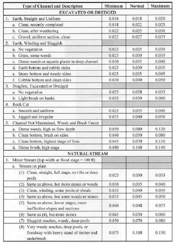
32 i) Experimental determination of the Manning roughness coefficient can be accomplished by measuring the depth of flowing water, the size and shape of the channel cross-section, and the volumetric flow rate for a given reach of channel. These measured values can be used to calculate an empirical value for n that can then be used for subsequent Manning equation calculations for that reach of channel. Example #9: Calculate the Manning roughness coefficient, n, for a reach of river channel that has a bottom slope of , with a cross-section that can be approximated as a trapezoid with bottom width equal to 8 ft and side slopes of horiz:vert = 4:1, if the flow rate has been estimated to be 75 cfs in that reach when the depth of water is 3 ¼ ft. Solution: The Manning equation can be solved for n to give: n = (1.49/Q)A(R h 2/3 )S 1/2 The area and hydraulic radius of the trapezoidal cross-section are calculated as follows: A = by + zy 2 = 8* * = ft 2 P = b + 2y(1 + z 2 ) 1/2 = 8 + 2*3.25( ) 1/2 = ft R h = A/P = 68.25/34.80 = 1.96 ft Substituting values into the above equation for n gives: n = (1.49/75)(68.25)(1.96 2/3 )( /2 ) = = n ii) There are Tables of n values in many textbooks and handbooks, as well as on websites. The table on the next two pages is an example from the Indiana Department of Transportation Design Manual (website ref # 1 ). Similar tables of n values are available on many state agency websites. The table below from the Indiana DOT Design Manual gives minimum, maximum, and normal values of the Manning roughness coefficient for a range of excavated or dredged and natural stream channels.
33

34 Table 3. Manning Roughness Coefficient, n, for Natural Channels
35 Example #10: What are the minimum, maximum, and normal values of the Manning roughness coefficient, n, for a minor mountain stream with no vegetation in the channel, banks usually steep, trees and brush along banks submerged at high stages, and cobbles with large boulders on the bottom, based on Table 3 below, from the Indiana DOT Design Manual? Solution: From Table 3, the values of n for the described natural channel are: nmin = 0.040, nmax = 0.07, nnormal = iii) The Cowan procedure was first presented in reference #4. There is also a good description of this method in McCuen (reference #5). This procedure uses a base n value with several terms added to it based on characteristics of the channel, as described below. 1. The Base Roughness Coefficient, n1, is selected from the following based on the character of the channel: Channels in earth: n 1 = 0.02 Channels cut into rock: n 1 = Channels in fine gravel: n 1 = Channels in coarse gravel: n 1 = The value for the Irregularity Modifier, n2, is selected from the following based on the degree of irregularity: Smooth (surface comparable to the best attainable for the materials involved) n 2 = Minor (good dredged channels; slightly eroded or scoured side slopes of canals) n 2 = 0.005
36 Moderate (fair to poor deredged channels; moderately sloughed or eroded canal side slopes) n 2 = Severe (badly sloughed banks of natural streams; badly eroded or sloughed sides of canals or drainage channels; unshaped, jagged and irregular surfaces of channels excavated in rock n 2 = The value for the Cross Section Modifier, n3, is selected from the following based on the character of variations in size & shape of cross section: Change in size or shape occurs gradually n 3 = Large & small sections alternate occasionally or shape changes cause occasional shifting of main flow from side to side n 3 = Large & small sections alternate frequently or shape changes cause frequent shifting of main flow from side to side n 3 = The value for the Obstruction Modifier, n4, is selected from the following based on the relative effect of obstructions: Negligible n 4 = Minor n 4 = Appreciable n 4 = Severe n 4 =
37 5. The value for the Vegetation Modifier, n5, is selected from the following based on the degree of vegetation effect on n: Low n 5 = Medium n 5 = Appreciable n 5 = Very High n 5 = The value for the Menadering Modifier, n6, is selected from the following based on the degree of meander: Minor ( meander length:straight length = ) n 6 = Appreciable ( meander length:straight length = ) n 6 = 0.15n s Severe ( meander length:straight length > 1.5 ) n 6 = 0.30n s Where n s = n 1 + n 2 + n 3 + n 4 + n 5 7. The value of the Manning Roughness Coefficient is calculated from: n = n1 + n2 + n3 + n4 + n5 + n6 Example #11: Estimate the value for the Manning roughness coefficient for a channel in earth with minor irregularity, only gradual changes in size or shape, minor obstructions, medium effect of vegetation, and minor meander.
38 Solution: From the lists above: n 1 = 0.02, n 2 = 0.005, n 3 = 0.000, n 4 = , n 5 = , and n 6 = Choosing the midpoint of the ranges given for n 4 and n 5 (n 4 = and n 5 = 0.015) gives the following equation for n: n = n = B. Manning Equation Calculations for natural channels are the same as for manmade channels except for less precision in estimating the Manning roughness coefficient and greater difficulty in determining the hydraulic radius if the channel cross-section isn t a simple shape. Example #12: A reach of channel of a minor stream on a plain is described as clean, winding, with some pools. The bottom slope is fairly constant at for this reach of channel. Its cross-section over this reach can be approximated as a trapezoid with a bottom width of 6 feet and side slopes of horiz:vert = 3:1. Find the range of flow rates that could be expected for this reach of channel for a 3.75 ft depth of flow, based on the maximum and minimum values of the Manning roughness coefficient from Table 3. Solution: From the information given in the problem statement, b = 6 ft, y = 3.75 ft, z = 3, and S = From Table 3 (for the channel description given in the problem statement), n min = and n max = From the equations for A, P, & R h for a trapezoidal open channel: R h = [(6)(3.75) + 3( )]/[6 + (2)(3.75)( ) 1/2 ] = ft A = (6)(3.75) + 3( ) = ft 2 Substituting values into the Manning Equation [Q = (1.49/n)A(R h 2/3 )S 1/2 ] gives the following results:
39 For n min (0.033): Q max = (1.49/0.033)(64.69)( /3 )( ) 1/2 Qmax = 86.4 ft 3 /sec For n max (0.045): Q min = (1.49/0.045)(64.69)( /3 )( ) 1/2 Qmin = 63.3 ft 3 /sec 9. Summary Open channel flow, which has a free liquid surface at atmospheric pressure, occurs in a variety of natural and man-made settings. Open channel flow may be classified as i) laminar or turbulent, ii) steady state or unsteady state, iii) critical, subcritical, or supercritical, and iv) uniform or nonuniform flow. Many practical cases of open channel flow can be treated as turbulent, steady state, uniform flow. Several open channel flow parameters are related through the empirical Manning Equation, for turbulent, uniform open channel flow (Q = (1.49/n)A(Rh 2/3 )S 1/2 ). The use of the Manning equation for uniform open channel flow calculations and for the calculation of parameters in the equation, such as cross-sectional area and hydraulic radius, are illustrated in this course through worked examples for manmade channels and for natural channels. 10. References and Websites 1. Munson, B. R., Young, D. F., & Okiishi, T. H., Fundamentals of Fluid Mechanics, 4 th Ed., New York: John Wiley and Sons, Inc, Steel, E.W. & McGhee, T.J., Water Supply and Sewerage, 5 th Ed., New York, McGraw-Hill Book Company, 1979.
40 3. Camp, T.R., Design of Sewers to Facilitate Flow, Sewage Works Journal, 18 (3), Cowan, W.L., "Estimating Hydraulic Roughness Coefficients," Agricultural Engineering, Vol. 37: , McCuen, R.H., Hydrologic Analysis and Design, 2nd Ed., Prentice Hall, Upper Saddle River, NJ, Bengtson, H.H., Partially Full Pipe flow Calculations with Excel Spreadsheets, an online article at 7. Bengtson, H.H., The Manning Equation for Open Channel Flow Calculations, available as a paperback and as an Amazon Kindle e-book. Websites: 1. Indiana Department of Transportation Design Manual, available on the internet at: 2. Illinois Department of Transportation Drainage Manual, available on the internet at: 3. Low Cost Easy to Use Excel Spreadsheets for Engineering Calculations, at
Open Channel Flow I - The Manning Equation and Uniform Flow COURSE CONTENT
 Open Channel Flow I - The Manning Equation and Uniform Flow Harlan H. Bengtson, PhD, P.E. COURSE CONTENT 1. Introduction Flow of a liquid may take place either as open channel flow or pressure flow. Pressure
Open Channel Hydraulics I - Uniform Flow
 PDHonline Course H138 (2 PDH) Open Channel Hydraulics I - Uniform Flow Instructor: Harlan H. Bengtson, Ph.D., PE 2012 PDH Online PDH Center 5272 Meadow Estates Drive Fairfax, VA 22030-6658 Phone & Fax:
Engineers Edge, LLC PDH & Professional Training
 510 N. Crosslane Rd. Monroe, Georgia 30656 (770) 266-6915 fax (678) 643-1758 Engineers Edge, LLC PDH & Professional Training Copyright, All Rights Reserved Engineers Edge, LLC Pipe Flow-Friction Factor
Pipe Flow/Friction Factor Calculations using Excel Spreadsheets
 Pipe Flow/Friction Factor Calculations using Excel Spreadsheets Harlan H. Bengtson, PE, PhD Emeritus Professor of Civil Engineering Southern Illinois University Edwardsville Table of Contents Introduction
Closed duct flows are full of fluid, have no free surface within, and are driven by a pressure gradient along the duct axis.
 OPEN CHANNEL FLOW Open channel flow is a flow of liquid, basically water in a conduit with a free surface. The open channel flows are driven by gravity alone, and the pressure gradient at the atmospheric
OPEN CHANNEL FLOW. One-dimensional - neglect vertical and lateral variations in velocity. In other words, Q v = (1) A. Figure 1. One-dimensional Flow
 A. Figure 1. One-dimensional Flow") OPEN CHANNEL FLOW Page 1 OPEN CHANNEL FLOW Open Channel Flow (OCF) is flow with one boundary exposed to atmospheric pressure. The flow is not pressurized and occurs because of gravity. Flow Classification
OPEN CHANNEL FLOW Page 1 OPEN CHANNEL FLOW Open Channel Flow (OCF) is flow with one boundary exposed to atmospheric pressure. The flow is not pressurized and occurs because of gravity. Flow Classification
Orifice and Venturi Pipe Flow Meters
 Orifice and Venturi Pipe Flow Meters by Harlan H. Bengtson, PhD, P.E. 1. Introduction Your Course Title Here The flow rate of a fluid flowing in a pipe under pressure is measured for a variety of applications,
Open Channel Hydraulics III - Sharpcrested
 PDHonline Course H140 (2 PDH) Open Channel Hydraulics III - Sharpcrested Weirs Instructor: Harlan H. Bengtson, Ph.D., PE 2012 PDH Online PDH Center 5272 Meadow Estates Drive Fairfax, VA 22030-6658 Phone
Open Channel Flow Part 2. Ch 10 Young, notes, handouts
 Open Channel Flow Part 2 Ch 10 Young, notes, handouts Uniform Channel Flow Many situations have a good approximation d(v,y,q)/dx=0 Uniform flow Look at extended Bernoulli equation Friction slope exactly
Presented by: Civil Engineering Academy
 Presented by: Civil Engineering Academy Open-Channel Flow Uniform Flow (See CERM Ch. 19) Characterized by constant depth volume, and cross section. It can be steady or unsteady Non-uniform Flow *Not on
Orifice and Venturi Pipe Flow Meters
 Orifice and Venturi Pipe Flow Meters For Liquid and Gas Flow by Harlan H. Bengtson, PhD, P.E. 1. Introduction Orifice and Venturi Pipe Flow Meters The flow rate of a fluid flowing in a pipe under pressure
GEOL 652. Poudre River Fieldtrip
 GEOL 652. Poudre River Fieldtrip One of the more difficult variables to measure and/or estimate when studying flow in natural channels is that of roughness. Roughness, usually approximated with Manning
presented by Umut Türker Open Channel Flow
 presented by Umut Türker Open Channel Flow What is open channel flow? Open channel flow is a flow which has a free surface and flows due to the gravitational effect What is open channel flow? Open channel
STEADY UNIFORM FLOW IN OPEN CHANNEL
 11/4/018 School of Environmental Engineering STEY UNIFORM FLOW IN OEN CHNNEL ZULKRNIN BIN HSSN COURSE OUTCOMES CO1: ble to analyze and design the steady flow in pipeline (O1) CO: ble to analyze and design
Basic Hydraulics June 2007
 Basic Hydraulics www.concrete-pipe.org June 2007 2007 Overview Open Channel Flow Manning Equation Basic Culvert Design Sanitary Sewer Design Flow, Velocity Stormwater Sewer Design Flow, Velocity 2 Open
DEPARTMENT OF CIVIL AND ENVIRONMENTAL ENGINEERING Urban Drainage: Hydraulics. Solutions to problem sheet 2: Flows in open channels
 DEPRTMENT OF CIVIL ND ENVIRONMENTL ENGINEERING Urban Drainage: Hydraulics Solutions to problem sheet 2: Flows in open channels 1. rectangular channel of 1 m width carries water at a rate 0.1 m 3 /s. Plot
Lecture Note for Open Channel Hydraulics
 Chapter -one Introduction to Open Channel Hydraulics 1.1 Definitions Simply stated, Open channel flow is a flow of liquid in a conduit with free space. Open channel flow is particularly applied to understand
We will assume straight channels with simple geometries (prismatic channels) and steady state flow (in time).
 and steady state flow (in time).") 56 Review Drag & Lift Laminar vs Turbulent Boundary Layer Turbulent boundary layers stay attached to bodies longer Narrower wake! Lower pressure drag! 8. Open-Channel Flow Pipe/duct flow closed, full,
56 Review Drag & Lift Laminar vs Turbulent Boundary Layer Turbulent boundary layers stay attached to bodies longer Narrower wake! Lower pressure drag! 8. Open-Channel Flow Pipe/duct flow closed, full,
Uniform Flow in Open Channels
 1 UNIT 2 Uniform Flow in Open Channels Lecture-01 Introduction & Definition Open-channel flow, a branch of hydraulics, is a type of liquid flow within a conduit with a free surface, known as a channel.
Open Channel Flow Measurement Weirs and Flumes
 Open Channel Flow Measurement Weirs and Flumes by Harlan H. Bengtson, PhD, P.E. 1. Introduction Measuring the flow rate of water in an open channel typically involves some type of obstruction in the path
FE Fluids Review March 23, 2012 Steve Burian (Civil & Environmental Engineering)
") Topic: Fluid Properties 1. If 6 m 3 of oil weighs 47 kn, calculate its specific weight, density, and specific gravity. 2. 10.0 L of an incompressible liquid exert a force of 20 N at the earth s surface.
Topic: Fluid Properties 1. If 6 m 3 of oil weighs 47 kn, calculate its specific weight, density, and specific gravity. 2. 10.0 L of an incompressible liquid exert a force of 20 N at the earth s surface.
UNIFORM FLOW CRITICAL FLOW GRADUALLY VARIED FLOW
 UNIFORM FLOW CRITICAL FLOW GRADUALLY VARIED FLOW Derivation of uniform flow equation Dimensional analysis Computation of normal depth UNIFORM FLOW 1. Uniform flow is the flow condition obtained from a
Hydraulics Part: Open Channel Flow
 Hydraulics Part: Open Channel Flow Tutorial solutions -by Dr. K.N. Dulal Uniform flow 1. Show that discharge through a channel with steady flow is given by where A 1 and A 2 are the sectional areas of
Basic Hydraulics. Rabi H. Mohtar ABE 325
 Basic Hydraulics Rabi H. Mohtar ABE 35 The river continues on its way to the sea, broken the wheel of the mill or not. Khalil Gibran The forces on moving body of fluid mass are:. Inertial due to mass (ρ
Effect of Roughness on Discharge
 Effect of Roughness on Discharge T.W. Lau, and N.R. Afshar Abstract These Water resource projects and hydraulic engineering works have been developing rapidly throughout the world, thus prediction of water
LECTURE 9: Open channel flow: Uniform flow, best hydraulic sections, energy principles, Froude number
 LECTURE 9: Open channel flow: Uniform flow, best hydraulic sections, energy principles, Froude number Assist. Prof. Neslihan SEMERCİ Marmara University Department of Environmental Engineering Open channel
Design Data 17. Partial Flow Conditions of Box Culverts
 Design Data 17 Partial Flow Conditions of Box Culverts Sewers, both sanitary and storm, are designed to carry a peak flow based on anticipated land development. The hydraulic capacity of sewers or culverts
STEADY FLOW THROUGH PIPES DARCY WEISBACH EQUATION FOR FLOW IN PIPES. HAZEN WILLIAM S FORMULA, LOSSES IN PIPELINES, HYDRAULIC GRADE LINES AND ENERGY
 STEADY FLOW THROUGH PIPES DARCY WEISBACH EQUATION FOR FLOW IN PIPES. HAZEN WILLIAM S FORMULA, LOSSES IN PIPELINES, HYDRAULIC GRADE LINES AND ENERGY LINES 1 SIGNIFICANCE OF CONDUITS In considering the convenience
Hydromechanics: Course Summary
 Hydromechanics: Course Summary Hydromechanics VVR090 Material Included; French: Chapters to 9 and 4 + Sample problems Vennard & Street: Chapters 8 + 3, and (part of it) Roberson & Crowe: Chapter Collection
Guo, James C.Y. (1999). "Critical Flow Section in a Collector Channel," ASCE J. of Hydraulic Engineering, Vol 125, No. 4, April.
. Critical Flow Section in a Collector Channel, ASCE J. of Hydraulic Engineering, Vol 125, No. 4, April.") Guo, James C.Y. (1999). "Critical Flow Section in a Collector Channel," ASCE J. of Hydraulic Engineering, Vol 15, No. 4, April. CRITICAL FLOW SECTION IN A COLLECTOR CHANNEL By James C.Y. Guo, PhD, P.E.
Guo, James C.Y. (1999). "Critical Flow Section in a Collector Channel," ASCE J. of Hydraulic Engineering, Vol 15, No. 4, April. CRITICAL FLOW SECTION IN A COLLECTOR CHANNEL By James C.Y. Guo, PhD, P.E.
MODELING FLUID FLOW IN OPEN CHANNEL WITH HORSESHOE CROSS SECTION
 July. 2. Vol. 7. No. 2 MODELING FLUID FLOW IN OPEN CHANNEL WITH HORSESHOE CROSS SECTION 1 J. JOMBA, 2 D.M.THEURI, 2 E. MWENDA, 2 C. CHOMBA ABSTRACT Flow in a closed conduit is regarded as open channel
NPTEL Quiz Hydraulics
 Introduction NPTEL Quiz Hydraulics 1. An ideal fluid is a. One which obeys Newton s law of viscosity b. Frictionless and incompressible c. Very viscous d. Frictionless and compressible 2. The unit of kinematic
FLOW IN CONDUITS. Shear stress distribution across a pipe section. Chapter 10
 Chapter 10 Shear stress distribution across a pipe section FLOW IN CONDUITS For steady, uniform flow, the momentum balance in s for the fluid cylinder yields Fluid Mechanics, Spring Term 2010 Velocity
Uniform Channel Flow Basic Concepts Hydromechanics VVR090
 Uniform Channel Flow Basic Concepts Hydromechanics VVR090 ppt by Magnus Larson; revised by Rolf L Feb 2014 SYNOPSIS 1. Definition of Uniform Flow 2. Momentum Equation for Uniform Flow 3. Resistance equations
OPEN CHANNEL FLOW. Computer Applications. Numerical Methods and. Roland Jeppson. CRC Press UNIVERSITATSB'BUOTHEK TECHNISCHE. INFORMATlONSBiBUOTHEK
 OPEN CHANNEL FLOW Numerical Methods and Computer Applications Roland Jeppson TECHNISCHE INFORMATlONSBiBUOTHEK UNIVERSITATSB'BUOTHEK HANNOVER Si. i. CRC Press Taylor &.Francis Group Boca Raton London New
Fluid Mechanics Prof. S.K. Som Department of Mechanical Engineering Indian Institute of Technology, Kharagpur
 Fluid Mechanics Prof. S.K. Som Department of Mechanical Engineering Indian Institute of Technology, Kharagpur Lecture - 42 Flows with a Free Surface Part II Good morning. I welcome you to this session
Hydraulics for Urban Storm Drainage
 Urban Hydraulics Hydraulics for Urban Storm Drainage Learning objectives: understanding of basic concepts of fluid flow and how to analyze conduit flows, free surface flows. to analyze, hydrostatic pressure
VARIED FLOW IN OPEN CHANNELS
 Chapter 15 Open Channels vs. Closed Conduits VARIED FLOW IN OPEN CHANNELS Fluid Mechanics, Spring Term 2011 In a closed conduit there can be a pressure gradient that drives the flow. An open channel has
Flow in Open Channel Flow Conditions
 Civil Engineering Hydraulics Flow The graduate with a Science degree asks, "Why does it work?" The graduate with an Engineering degree asks, "How does it work?" The graduate with an Accounting degree asks,
New approach for the computation of Flow velocity in partially filled pipes Arranged In parallel
 New approach for the computation of Flow velocity in partially filled pipes Arranged In parallel Lotfi ZEGHADNIA, 1, Lakhdar DJEMILI 2, Rezgui Nouredin 1 1 Departement of Civil Engineering, Faculty of
Fluid Flow Analysis Penn State Chemical Engineering
 Fluid Flow Analysis Penn State Chemical Engineering Revised Spring 2015 Table of Contents LEARNING OBJECTIVES... 1 EXPERIMENTAL OBJECTIVES AND OVERVIEW... 1 PRE-LAB STUDY... 2 EXPERIMENTS IN THE LAB...
Pressure Head: Pressure head is the height of a column of water that would exert a unit pressure equal to the pressure of the water.
 Design Manual Chapter - Stormwater D - Storm Sewer Design D- Storm Sewer Sizing A. Introduction The purpose of this section is to outline the basic hydraulic principles in order to determine the storm
FLOW FRICTION CHARACTERISTICS OF CONCRETE PRESSURE PIPE
 11 ACPPA TECHNICAL SERIES FLOW FRICTION CHARACTERISTICS OF CONCRETE PRESSURE PIPE This paper presents formulas to assist in hydraulic design of concrete pressure pipe. There are many formulas to calculate
Open Channel Flow K Subramanya Solution Manual
 We have made it easy for you to find a PDF Ebooks without any digging. And by having access to our ebooks online or by storing it on your computer, you have convenient answers with open channel flow k
Lecture 13 Flow Measurement in Pipes. I. Introduction
 Lecture 13 Flow Measurement in Pipes I. Introduction There are a wide variety of methods for measuring discharge and velocity in pipes, or closed conduits Many of these methods can provide very accurate
Flow Measurement in Pipes and Ducts COURSE CONTENT
 Flow Measurement in Pipes and Ducts Dr. Harlan H. Bengtson, P.E. COURSE CONTENT 1. Introduction This course is about measurement of the flow rate of a fluid flowing under pressure in a closed conduit.
FLUID MECHANICS PROF. DR. METİN GÜNER COMPILER
 FLUID MECHANICS PROF. DR. METİN GÜNER COMPILER ANKARA UNIVERSITY FACULTY OF AGRICULTURE DEPARTMENT OF AGRICULTURAL MACHINERY AND TECHNOLOGIES ENGINEERING 1 5. FLOW IN PIPES Liquid or gas flow through pipes
Atmospheric pressure. 9 ft. 6 ft
 Name CEE 4 Final Exam, Aut 00; Answer all questions; 145 points total. Some information that might be helpful is provided below. A Moody diagram is printed on the last page. For water at 0 o C (68 o F):
CE 6403 APPLIED HYDRAULIC ENGINEERING UNIT - II GRADUALLY VARIED FLOW
 CE 6403 APPLIED HYDRAULIC ENGINEERING UNIT - II GRADUALLY VARIED FLOW Dynamic equations of gradually varied and spatially varied flows - Water surface flow profile classifications: Hydraulic Slope, Hydraulic
Advanced Hydraulics Prof. Dr. Suresh A. Kartha Department of Civil Engineering Indian Institute of Technology, Guwahati
 Advanced Hydraulics Prof. Dr. Suresh A. Kartha Department of Civil Engineering Indian Institute of Technology, Guwahati Module - 2 Uniform Flow Lecture - 1 Introduction to Uniform Flow Good morning everyone,
CHAPTER 07 CANAL DESIGN
 CHAPTER 07 CANAL DESIGN Dr. M. R. Kabir Professor and Head, Department of Civil Engineering University of Asia Pacific (UAP), Dhaka LECTURE 17 Canal Design Types Canal Design Drainage Channel Design Irrigation
Water Flow in Open Channels
 The Islamic Universit of Gaza Facult of Engineering Civil Engineering Department Hdraulics - ECIV 33 Chapter 6 Water Flow in Open Channels Introduction An open channel is a duct in which the liquid flows
P = 2Rθ. The previous Manning formulas are used to predict V o and Q for uniform flow when the above expressions are substituted for A, P, and R h.
 Uniform Flow in a Partly Full, Circular Pipe Fig. 10.6 shows a partly full, circular pipe with uniform flow. Since frictional resistance increases with wetted perimeter, but volume flow rate increases
53:071 Principles of Hydraulics Laboratory Experiment #3 ANALYSIS OF OPEN-CHANNEL FLOW TRANSITIONS USING THE SPECIFIC ENERGY DIAGRAM
 53:071 Principles of Hydraulics Laboratory Experiment #3 ANALYSIS OF OPEN-CHANNEL FLOW TRANSITIONS USING THE SPECIFIC ENERGY DIAGRAM Principle Adaptation of the Bernoulli equation to open-channel flows
Review of pipe flow: Friction & Minor Losses
 ENVE 204 Lecture -1 Review of pipe flow: Friction & Minor Losses Assist. Prof. Neslihan SEMERCİ Marmara University Department of Environmental Engineering Important Definitions Pressure Pipe Flow: Refers
5. ROADSIDE AND MEDIAN CHANNELS
 5. ROADSIDE AND MEDIAN CHANNELS Roadside and median channels are open-channel systems which collect and convey stormwater from the pavement surface, roadside, and median areas. These channels may outlet
The most common methods to identify velocity of flow are pathlines, streaklines and streamlines.
 4 FLUID FLOW 4.1 Introduction Many civil engineering problems in fluid mechanics are concerned with fluids in motion. The distribution of potable water, the collection of domestic sewage and storm water,
Properties and Definitions Useful constants, properties, and conversions
 Properties and Definitions Useful constants, properties, and conversions gc = 32.2 ft/sec 2 [lbm-ft/lbf-sec 2 ] ρwater = 1.96 slugs/ft 3 γwater = 62.4 lb/ft 3 1 ft 3 /sec = 449 gpm 1 mgd = 1.547 ft 3 /sec
3.2 CRITICAL DEPTH IN NONRECTANGULAR CHANNELS AND OCCUR- RENCE OF CRITICAL DEPTH
 3.2 CRITICAL DEPTH IN NONRECTANGULAR CHANNELS AND OCCUR- RENCE OF CRITICAL DEPTH Critical Depth in Non-Rectangular Channels Consider an irregular channel: da w dd dd d Specific energy is defined as: E
PENNSYLVANIA DEPARTMENT OF TRANSPORTATION ENGINEERING DISTRICT 3-0
 PENNSYLVANIA DEPARTMENT OF TRANSPORTATION ENGINEERING DISTRICT 3-0 LYCOMING COUNTY S.R.15, SECTION C41 FINAL HYDROLOGIC AND HYDRAULIC REPORT STEAM VALLEY RUN STREAM RELOCATION DATE: June, 2006 REVISED:
CIE4491 Lecture. Hydraulic design
 CIE4491 Lecture. Hydraulic design Marie-claire ten Veldhuis 19-9-013 Delft University of Technology Challenge the future Hydraulic design of urban stormwater systems Focus on sewer pipes Pressurized and
Hydraulics Prof. Dr. Arup Kumar Sarma Department of Civil Engineering Indian Institute of Technology, Guwahati
 Hydraulics Prof. Dr. Arup Kumar Sarma Department of Civil Engineering Indian Institute of Technology, Guwahati Module No. # 04 Gradually Varied Flow Lecture No. # 07 Rapidly Varied Flow: Hydraulic Jump
Influence of Two-line Emergent Floodplain Vegetation on A Straight Compound Channel Flow
 International Journal of Integrated Engineering, Vol. 5 No. 1 (2013) p. 58-63 Influence of Two-line Emergent Floodplain Vegetation on A Straight Compound Channel Flow Mazlin Jumain 1,*, Zulkiflee Ibrahim
CEE 3310 Open Channel Flow,, Nov. 18,
 CEE 3310 Open Channel Flow,, Nov. 18, 2016 165 8.1 Review Drag & Lit Laminar vs Turbulent Boundary Layer Turbulent boundary layers stay attached to bodies longer Narrower wake! Lower pressure drag! C D
Open Channel Flow - General. Hydromechanics VVR090
 Open Channel Flow - General Hydromechanics VVR090 ppt by Magnus Larson; revised by Rolf L Jan 2014, Feb 2015 SYNOPSIS 1. Introduction and Applications 2. The History of Open Channel Flow 3. Flow Classification
Geomorphology Geology 450/750 Spring Fluvial Processes Project Analysis of Redwood Creek Field Data Due Wednesday, May 26
 Geomorphology Geology 450/750 Spring 2004 Fluvial Processes Project Analysis of Redwood Creek Field Data Due Wednesday, May 26 This exercise is intended to give you experience using field data you collected
Gradually Varied Flow I+II. Hydromechanics VVR090
 Gradually Varied Flow I+II Hydromechanics VVR090 Gradually Varied Flow Depth of flow varies with longitudinal distance. Occurs upstream and downstream control sections. Governing equation: dy dx So Sf
Technical Memorandum. To: From: Copies: Date: 10/19/2017. Subject: Project No.: Greg Laird, Courtney Moore. Kevin Pilgrim and Travis Stroth
 Technical Memorandum To: From: Greg Laird, Courtney Moore Kevin Pilgrim and Travis Stroth 5777 Central Avenue Suite 228 Boulder, CO 80301 www.otak.com Copies: [Electronic submittal] Date: 10/19/2017 Subject:
EXPERIMENTAL STUDY OF BACKWATER RISE DUE TO BRIDGE PIERS AS FLOW OBSTRUCTIONS
 Tenth International Water Technology Conference, IWTC1 6, Alexandria, Egypt 19 EXPERIMENTAL STUDY OF BACKWATER RISE DUE TO BRIDGE PIERS AS FLOW OBSTRUCTIONS Kassem Salah El-Alfy Associate Prof., Irrigation
Chapter 8: Flow in Pipes
 Objectives 1. Have a deeper understanding of laminar and turbulent flow in pipes and the analysis of fully developed flow 2. Calculate the major and minor losses associated with pipe flow in piping networks
Department of Hydro Sciences, Institute for Urban Water Management. Urban Water
 Department of Hydro Sciences, Institute for Urban Water Management Urban Water 1 Global water aspects Introduction to urban water management 3 Basics for systems description 4 Water transport 5 Matter
Visualization of flow pattern over or around immersed objects in open channel flow.
 EXPERIMENT SEVEN: FLOW VISUALIZATION AND ANALYSIS I OBJECTIVE OF THE EXPERIMENT: Visualization of flow pattern over or around immersed objects in open channel flow. II THEORY AND EQUATION: Open channel:
Open Channel Flow - General. Open Channel Flow
 Open Channel Flow - General Hydromechanics VVR090 Open Channel Flow Open channel: a conduit for flow which has a free surface Free surface: interface between two fluids of different density Characteristics
Chapter 8: Flow in Pipes
 8-1 Introduction 8-2 Laminar and Turbulent Flows 8-3 The Entrance Region 8-4 Laminar Flow in Pipes 8-5 Turbulent Flow in Pipes 8-6 Fully Developed Pipe Flow 8-7 Minor Losses 8-8 Piping Networks and Pump
Fluid Mechanics Prof. T.I. Eldho Department of Civil Engineering Indian Institute of Technology, Bombay. Lecture - 17 Laminar and Turbulent flows
 Fluid Mechanics Prof. T.I. Eldho Department of Civil Engineering Indian Institute of Technology, Bombay Lecture - 17 Laminar and Turbulent flows Welcome back to the video course on fluid mechanics. In
Convection. forced convection when the flow is caused by external means, such as by a fan, a pump, or atmospheric winds.
 Convection The convection heat transfer mode is comprised of two mechanisms. In addition to energy transfer due to random molecular motion (diffusion), energy is also transferred by the bulk, or macroscopic,
P10.5 Water flows down a rectangular channel that is 4 ft wide and 3 ft deep. The flow rate is 15,000 gal/min. Estimate the Froude number of the flow.
 P10.5 Water flows down a rectangular channel that is 4 ft wide and ft deep. The flow rate is 15,000 gal/min. Estimate the Froude number of the flow. Solution: Convert the flow rate from 15,000 gal/min
Lateral Inflow into High-Velocity Channels
 Lateral Inflow into High-Velocity Channels by Richard L. Stockstill PURPOSE: This Coastal and Hydraulics Engineering Technical Note (CHETN) investigates lateral flow discharging into a high-velocity channel.
Fundamentals of Fluid Mechanics
 Sixth Edition Fundamentals of Fluid Mechanics International Student Version BRUCE R. MUNSON DONALD F. YOUNG Department of Aerospace Engineering and Engineering Mechanics THEODORE H. OKIISHI Department
GLG598 Surface Processes and Landform Evolution K. Whipple Fall 2012 VERDE RIVER: FLOW MECHANICS, ROUGHNESS, AND SHEAR STRESS
 VERDE RIVER: FLOW MECHANICS, ROUGHNESS, AND SHEAR STRESS This lab will introduce you to some common field techniques and some general understanding of the geomorphic processes operating in a stream. The
Q = α n AR2/3 h S1/2 0. bd 2d + b d if b d. 0 = ft1/3 /s
 CEE 330 Open Channel Flow, Nov., 00 7 8.8 Review Open Channel Flow Gravity friction balance. In general we take an energy equation approach. y Uniform Flow x = 0 z = S 0L = h f where we could find h f
Lab 7: Nonuniform Flow and Open Channel Transitions
 CE 3620: Water Resources Engineering Spring 2015 Lab 7: Nonuniform Flow and Open Channel Transitions BACKGROUND An open channel transition may be defined as a change either in the direction, slope, or
Bernoulli and Pipe Flow
 Civil Engineering Hydraulics Mechanics of Fluids Head Loss Calculations Bernoulli and The Bernoulli equation that we worked with was a bit simplistic in the way it looked at a fluid system All real systems
Formation Of Hydraulic Jumps On Corrugated Beds
 International Journal of Civil & Environmental Engineering IJCEE-IJENS Vol:10 No:01 37 Formation Of Hydraulic Jumps On Corrugated Beds Ibrahim H. Elsebaie 1 and Shazy Shabayek Abstract A study of the effect
FORMATION OF HYDRAULIC JUMPS ON CORRUGATED BEDS
 International Journal of Civil & Environmental Engineering IJCEE-IJENS Vol: 10 No: 01 40 FORMATION OF HYDRAULIC JUMPS ON CORRUGATED BEDS Ibrahim H. Elsebaie 1 and Shazy Shabayek Abstract A study of the
CONCEPTS Conservational Channel Evolution and Pollutant Transport System
 CONCEPTS Conservational Channel Evolution and Pollutant Transport System Eddy J. Langendoen Watershed Physical Processes Research Unit National Sedimentation Laboratory USDA Agricultural Research Service
ME 305 Fluid Mechanics I. Chapter 8 Viscous Flow in Pipes and Ducts
 ME 305 Fluid Mechanics I Chapter 8 Viscous Flow in Pipes and Ducts These presentations are prepared by Dr. Cüneyt Sert Department of Mechanical Engineering Middle East Technical University Ankara, Turkey
Reservoir Oscillations with Through Flow
 American Journal of Environmental Sciences 3 (): 37-42, 27 ISSN 553-345X 27 Science Publications Reservoir Oscillations with Through Flow A. A. Khan 28 Lowry Hall, epartment of Civil Engineering, Clemson
Dr. Muhammad Ali Shamim ; Internal 652
 Dr. Muhammad Ali Shamim ali.shamim@uettaxila.edu.pk 051-904765; Internal 65 Channel Tranistions A channel transition is defined as change in channel cross section e.g. change in channel width and/or channel
1 Branch: CIVIL ENGINEERING Sub: HYDRAULICS AND HYDRAULIC MACHINERY Date: 11/03/2017
 G.PULLAIAH COLLEGE OF ENGINEERING & TECHNOLOGY (AT) II B.Tech Objective Paper I MID EXAM 1 Branch: CIVIL ENGINEERING Sub: HYDRAULICS AND HYDRAULIC MACHINERY Date: 11/03/2017 Time: 20 min Max.Marks:10 Roll
Open-channel hydraulics
 Open-channel hydraulics STEADY FLOW IN OPEN CHANNELS constant discharge, other geometric and flow characteristics depended only on position Uniform flow Non-uniform flow S; y; v const. i i 0 i E y 1 y
Beaver Creek Corridor Design and Analysis. By: Alex Previte
 Beaver Creek Corridor Design and Analysis By: Alex Previte Overview Introduction Key concepts Model Development Design Accuracy Conclusion Refresh v = Beaver Creek Site = Wittenberg Introduction Low head
Analysis of Flow Resistance for Different Bed Materials with Varying Discharge Experimentally in Open Channels
 Analysis of Flow Resistance for Different Bed Materials with Varying Discharge Experimentally in Open Channels Lakshmi Mitra 1, Dr.Mimi Das Saikia 2 M.Tech. Student, Department of Civil Engineering, Assam
Flow Measurement in Pipes and Ducts
 Flow Measurement in Pipes and Ducts Course No: M04-040 Credit: 4 PDH Harlan H. Bengtson, Ph.D., P.E. Continuing Education and Development, Inc. 9 Greyridge Farm Court Stony Point, NY 10980 P: (877) 322-5800
Habitat Assessment. Peggy Compton UW-Extension Water Action Volunteers Program Coordinator
 Habitat Assessment Peggy Compton UW-Extension Water Action Volunteers Program Coordinator Adapted from a presentation by Jean Unmuth, Water Quality Biologist, WI DNR dnr.wi.gov www.uwex.edu erc.cals.wisc.edu
Flow Measurement in Pipes and Ducts COURSE CONTENT
 Flow Measurement in Pipes and Ducts Dr. Harlan H. Bengtson, P.E. COURSE CONTENT 1. Introduction This course is about measurement of the flow rate of a fluid flowing under pressure in a closed conduit.
Advanced Hydraulics Prof. Dr. Suresh A Kartha Department of Civil Engineering Indian Institute of Technology, Guwahati
 Advanced Hydraulics Prof. Dr. Suresh A Kartha Department of Civil Engineering Indian Institute of Technology, Guwahati Module - 2 Uniform Flows Lecture - 6 Design of Channels for Uniform Flow (Refer Slide
Uniform Channel Flow Basic Concepts. Definition of Uniform Flow
 Uniform Channel Flow Basic Concepts Hydromechanics VVR090 Uniform occurs when: Definition of Uniform Flow 1. The depth, flow area, and velocity at every cross section is constant 2. The energy grade line,
Chapter 10 Flow in Conduits
 Chapter 10 Flow in Conduits 10.1 Classifying Flow Laminar Flow and Turbulent Flow Laminar flow Unpredictable Turbulent flow Near entrance: undeveloped developing flow In developing flow, the wall shear