Laboratory-on-chip based sensors Part 2: Capacitive measurements
|
|
|
- Delilah Rice
- 5 years ago
- Views:
Transcription


1 GBM8320 Dispositifs Médicaux Intelligents Laboratory-on-chip based sensors Part 2: Capacitive measurements Mohamad Sawan et al. Laboratoire de neurotechnologies Polystim!!! M February 2012
2 Laboratory-on-Chip : Outline I. Introduction II. Biochemistry III. Microfluidic Packaging IV. Capacitive Sensors V. Cells Manipulation and Detection. GBM Dispositifs Médicaux Intelligents 2
3 Laboratory-on-Chip : Capacitive sensors GBM Dispositifs Médicaux Intelligents 3


4 Laboratory-on-Chip : Capacitor sensors Capacitive sensors for LoC applications do not require determining a single value of the sensing capacitance, but to distinguish between the device behavior in the presence rather than in the absence of analyte in microfluidic channel. 3D Accelerometer Low complexity Array of capacitive sensors Offset cancellation Sandia National Laboratories, SUMMiT TM Technologyies Capacitive sensor LOC E.coli Bacteria Ghafar-Zadeh & Sawan, IEEE-IMST3W 2008 GBM Dispositifs Médicaux Intelligents 4

5 LoC : Charge-Based Capacitive Measurement Interconnect or sensing capacitance can be retrieved/measured from the following equation: (I S I R ) = f V dd ΔC where Originated ΔC = Cs - C0, and C0 = CR Year 1997 UC Berkeley ΔC IR CR M3 B M4 Vdd CBCM F1 M1 A F2 M2 Gnd Is CS External tools Main application DC Ammeter Capacitance characterization F1 F2 Resolution Sub femtofarad Frequency <15 MHz GBM Dispositifs Médicaux Intelligents 5
6 LoC : CBCM-based capacitive sensor Current mirror and integrating capacitor instead of dc Ammeter. ( Vdd VTP ) CS VS = ( Vdd VTP ) dv K ( V V ) t + C S 2 CS = K x ( Vgs VTP ) Vdd-Vs=Vgs 2 dt [( Vdd VTP ) CS ] K x AI 1 I( CS, t) 2 F1, F2 Low K ( V V ) t + C F1 F2 V d d A I S M 1 C A M 2 F1 F2 M 1 V d d M 3 M 4 Vs Cs M 2 x dd TP S [ ] x dd TP S Is I(Cs,t) Is Vout Cin Cin Ghafar-zadeh, Sawan, IEEE TBioCAS, 2007 GBM Dispositifs Médicaux Intelligents 6

, Voff does not affect the accuracy, but large Voff may limit the dynamic range, then Voff should be minimized.")
7 LoC : CBCM-based capacitive sensor C in dv dt out = I S dv S s CS = dt A I Δ C + C V = A ( V V ) + V 0 out I dd TP Cin F2 Cancellation of C0 (C0 >> ΔC ) Accurate reference current IR is needed. V out = A I Cs C in (V dd V TP ) + V off I 0 F1 M 1 M 2 V d d A I S C F1 F2 Is/AI Vout Reset mode Charging mode Sampling Voff = f(mismatch in process, remnant in channel), Voff does not affect the accuracy, but large Voff may limit the dynamic range, then Voff should be minimized. ΔC << Cp, the effect of Cp is almost cancelled by measuring CS-CR before converting to voltage. IR Is Vout GBM Dispositifs Médicaux Intelligents 7

8 LoC : CBCM-based capacitive sensor Vdd M3 M5 1.5 ΔC=3fF 1.3 CBCM* F1 M1 ID1 Vout Vout (V) m ΔC=2fF ΔC=1fF F2 M13 Gnd CS Cint Is M10 Ck5 700m 500m ΔC=0 300m µ 200µ 300µ 400µ Time (s) Gnd GBM Dispositifs Médicaux Intelligents 8


9 LoC : CBCM-based capacitive sensor In agreement with the calculation and simulation; Higher dielectric constant of organic solvent, higher output voltage. ID1 F1 M F2 M Vb1 7 CS Gnd Vout Is M1 13 F1 M5 M3 CBCM* Dichloromethane Injection Methanol Injection Vout Is-IR IR F2 Vout Cint Gnd M10 Gnd GBM Dispositifs Médicaux Intelligents 9

10 Laboratory-on-Chip : Outline Large interdigitated electrode CBCM structure. Sensing electrodes Microchannel F1 Vdd M1 Φ2 Outlet M2 Φ1 M1 A Φ1 Inlet Vdd F2 M2 Interdigitated electrode CBCM Process Φ µm CMOS Gnd Sensing electrode µm² Vdd 1.8 Volt Frequency (f) CBCM E1 Cp1 Cs 100Hz-1MHz E2 E2 Cs/2 Cp1 Cp1 Analyte Passivation layers E1 Cp1 Cs/2 Cp1 E2 Cp2 CM-S CBCM Cp2 CM-s Cp2 Ghafar-Zadeh, E., Sawan, M., IEEE TBioCAS, 2007 GBM Dispositifs Médicaux Intelligents 10

11 LoC : CBCM-based capacitive sensor Microscopic images of chip. Interdigitated electrodes Passivation layer removal Reference and sensing electrodes. Ghafar-Zadeh et al, Sensors and Actuators A: Physical, 2008 GBM Dispositifs Médicaux Intelligents 11
 9.4 9.0 Dichloromethane (D) 10.8 Acetone (A) 20.0 Methanol (M) 32.0 Deionised water (W) 80.8 Saline water (S) conductive 0.4 0 40 80 Dielectric constant 8.")
12 LoC : CBCM-based capacitive sensor C (pf) Sensing capacitances values for different analytes; Parasitic capacitances of different chip samples; Average of recorded samples from 3 electrodes C0 (pf) Dichloromethane (D) 10.8 Acetone (A) 20.0 Methanol (M) 32.0 Deionised water (W) 80.8 Saline water (S) conductive Dielectric constant Measured chips The recorded data for a particular organic solvent shows a decoded output of a 6-bit resolution. GBM Dispositifs Médicaux Intelligents 12
 900 700")

13 LoC : CBCM : Linearity & mismatch error Mismatch only affects an offset voltage M7 M4 M2 M % change of 1100 W1 W2 W3 W4 IR Vb1 IR M3 F1 M1 IS Vout Vb1 Vout (mv) W5 W6 W7 W8 CR M8 F2 M6 CS Cint % change in Wi Reset mode Vout Sampled voltage Cs (ff) GBM Dispositifs Médicaux Intelligents 13
14 LoC : CBCM-based capacitive sensor Cancellation of Vos Vdd Rp through Rp; A replica of sensing circuit is employed to generate reference current. M8 IR CR M10 M7 ID2 M2 M4 SR F2 Gnd Cin M1 M5 Cs M3 IS - IR ID1 M6 IS M9 FPGA F1 F2 Vo Gnd GBM Dispositifs Médicaux Intelligents 14
15 Laboratory-on-Chip : Outline Non-linearity of output voltage versus Rp1 and Rp2. Rp1 Rp2 1.2 Vdd Vo (V) 1.1 Rp2 M8 M7 M2 1.0 CR B M4 0.9 IR Rp1/2 (kohms) M10 M9 GBM Dispositifs Médicaux Intelligents 15
16 Laboratory-on-Chip : Outline Adjustable current mirror gain (D1-Dm) Three stages unity current mirror. M13 M 1 3 V d d B A I s S 1 A CBCM IR Q2 Q1 CBCM V a V b C M 10 M 9 M 8 V c M 14 I M 5 V o u t B M c m M c 1 M 15 S W 1 M 6 D m D 1 M 7 C GBM Dispositifs Médicaux Intelligents 16
17 Laboratory-on-Chip : Outline Adjustable current mirror gain (D1-Dm) 1-bit DAC Calibration circuit Vdd MDAC MCM MC1 M6 M4 M3 M5 SDAC SCM SC1 qn Dm D1 IDAC IR Vb1 M8 Vb2 M10 CR IR M2 M14 CBCM Ck1 Ck2 Gnd M1 M13 ID1 Is M7 CS Vb2 M9 Cint M11 Vb1 Vout Is-IR Ck3 M12 Gnd I R = I R0 (1 + 2 m-1 D C m-k D Ck + + D CM ). M10 GBM Dispositifs Médicaux Intelligents 17
18 Laboratory-on-Chip : Outline By adding a voltage comparator and a switch in series with a current source, a DC input sigma delta can be realized. x n I x + LPF q n Vout V R 1-bit DAC I s Xn q n = I x x Sw1 I x - + V R I(Cs, t) V o C i n Sw2 F 1 F n Q 1 Q 2 Ghafar-zadeh & Sawan, J. of IEEE Sensors, no.4, 2008 GBM Dispositifs Médicaux Intelligents 18
 V o C i n Sw2 Vout (output pulse) Q 1 Q 2 1. 8 C = 0.")
19 Laboratory-on-Chip : Sigma-Delta ADC Xn Post-layout simulation results Unique sequence. I x Sw1 - + V R I(Cs, t) V o C i n Sw2 Vout (output pulse) Q 1 Q C = 0.3 ff (V) C = 0.22 ff Time (msec) GBM Dispositifs Médicaux Intelligents 19
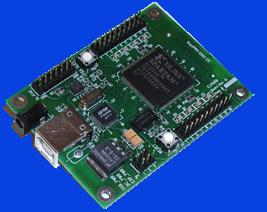
20 Laboratory-on-Chip : Outline An array of capacitive sensors. O f f - c h i p F P G A S y s t e m CS1 CS2 CS3 Adjustable reference current. Sigma-Delta DC A/D converter Offset cancellation procedure ( FPGA). Stop calibration & recording D1-m N o F 1 F 2 S1 S2 S3 U < V t h D 1 - m = D 1 - m + 1 Y e s ADC Reset UIC1 S 1 V o u t B u f f e r UIC2 S 2 I s Cin CR UIC3 S 3 I R Ajustable Current Mirror D 1-8 f s VR On-chip circuit GBM Dispositifs Médicaux Intelligents 20
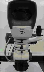
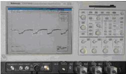


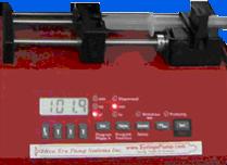


21 Laboratory-on-Chip : Measurement set-up GBM Dispositifs Médicaux Intelligents 21
22 Laboratory-on-Chip : Outline ( I I ) = f V ΔC S R dd log( I I ) = log f + log( V ΔC) 2 1 dd ΔC where Cs=ΔC+C0 Extraction of sensing capacitance variation 10 Log (I2-I1) Dichloromethane Acetone Methanol DI water ( C0: Parasitic capacitance) D C B A 1E1 1E2 1E3 f(hz) 1E4 1E5 1E6 GBM Dispositifs Médicaux Intelligents 22

23 Laboratory-on-Chip : Outline Microscopic image of fabricated chip (a) Die including the electrodes and sigma delta sensor, (b) Interdigitated electrode. Ghafar-Zadeh et al, Sensors and Actuators A: Physical, 2008 GBM Dispositifs Médicaux Intelligents 23

24 Laboratory-on-Chip : Bacteria growth monitoring GBM Dispositifs Médicaux Intelligents 24

25 Laboratory-on-Chip : Outline Illustration of the proposed system for Bacteria-on- Chip monitoring: LB : medium for bacteria Bacteria settles on the surface of chip which results in a capacitive element. GBM Dispositifs Médicaux Intelligents 25
26 Laboratory-on-Chip : Bacteria growth monitoring Output of sensor versus parameters V C = 1 T = 2t t T RBC1 RL CB (C Vdd VTP e e AI ( C 0 in RB RL (C / 2 1 / 2) )dt /2) T >> 0 1 B 1 (V dd VTP ) AI + Cin C C + V Instead of Impedance measurement with R, we measure here only Cs. V OS OS GBM Dispositifs Médicaux Intelligents 26


27 Laboratory-on-Chip : Bacteria growth monitoring GBM Dispositifs Médicaux Intelligents 27


28 Laboratory-on-Chip : Magnetic manipulation Carbon array of electrodes used to push the bacteria toward the sensing electrode for measurement. GBM Dispositifs Médicaux Intelligents 28

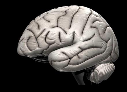


29 Laboratory-on-Chip : Cells Detection/manipulation LoC Intracortical neural Control Data acquisition Implantable devices Neurotransmitter detection & separation High sensitivity / selectivity Target diseases: Epilepsy Alzheimer Parkinson GBM Dispositifs Médicaux Intelligents 29

 Output signal referring to liquid concentration")


30 Laboratory-on-Chip : Cells Detection/manipulation Actuation electrode matrix Quadrature signals Sensing electrodes: capacitive sensor * DEP force CMOS chip ** (0.18µm) Output signal referring to liquid concentration Actuation module: Frequency / Magnitude control CMOS chip ** (0.18µm) Acquisition module: CBCM technique * Technology: Mixed CMOS-Microfluidic ** The same CMOS chip include both the acquisition and actuation module. GBM Dispositifs Médicaux Intelligents 30
31 Laboratory-on-Chip : References 1. A. Romani et al Capacitive sensor array for localization of bioparticles in CMOS lab-on-achip, Digest of Technical Papers, IEEE ISSCC Conf., 2004, pp D. Sylvester et al, Investigation of interconnect capacitance characterization using CBCM technique and three-dimensional simulation, IEEE JSSC, Vol. 33, no. 3, C. Guiducci, C. Stagni, G. Zuccheri, "DNA detection by integrable electronics," J.. Biosensors and Bioelectronics, vol. 19, no. 9, A. Hierlemann, Integrated Chemical Microsensor Systems in CMOS Technology, New York: Springer-Verlag, E. Ghafar-Zadeh, M. Sawan and D. Therriault, Novel direct-write CMOS-based laboratoryon-chip: Design, assembly and experimental results, Sensors and Actuators A: Physical, Volume 134, Issue 1, 28 February 2007, Pages E. Ghafar-Zadeh, M. Sawan, A Core-CBCM Sigma Delta Capacitive Sensor Array Dedicated to Lab-on-Chip Applications, In press in Sensors & Actuators: A. Physical 7. E. Ghafar-Zadeh, M. Sawan and D. Therriault, A Microfluidic Packaging Technique for Labon-Chip Applications, In press IEEE Trans. on Advanced Packaging. 8. E. Ghafar-Zadeh, M. Sawan, Charge-Based Capacitive Sensor Array for CMOS-Based Laboratory-On-Chip Applications, IEEE Sensors, Vol. 8, No. 4, April 2008, pp E. Ghafar-Zadeh, M. Sawan, A Hybrid Microfluidic/CMOS Capacitive Sensor Dedicated to Lab-on-Chip Applications, IEEE TBioCAS, Vol. 1, No. 4, December 2007, pp GBM Dispositifs Médicaux Intelligents 31
32 Quizz 1. Capacitive sensor is optimized to: a. Mesure a single value of the capacitance b. Mesure a capacitance change c. Mesure liquid concentration d. Mesure liquid concentration change GBM Dispositifs Médicaux Intelligents 32
33 Quizz 1. Capacitive sensor is optimized to: a. Mesure a single value of the capacitance b. Mesure a capacitance change c. Mesure liquid concentration d. Mesure liquid concentration change GBM Dispositifs Médicaux Intelligents 33
34 Quiz 2. CBCM measures: a. Capacitance change b. Current change c. Voltage change d. Resistance change GBM Dispositifs Médicaux Intelligents 34
35 Quiz 2. CBCM measures: a. Capacitance change b. Current change c. Voltage change d. Resistance change GBM Dispositifs Médicaux Intelligents 35
36 Quiz 3. When you design interdigitited electrodes on the top of a CMOS chip: a. You have to remove the passivation layer b. You have to add an isolation layer c. You have to add Poly layer d. (a,b and c) GBM Dispositifs Médicaux Intelligents 36
37 Quiz 3. When you design interdigitited electrodes on the top of a CMOS chip: a. You have to remove the passivation layer b. You have to add an isolation layer c. You have to add Poly layer d. (a,b and c) GBM Dispositifs Médicaux Intelligents 37
38 Quiz 4. LoC contains a. Only microfluidic chip b. Only Microelectronic chip c. Only MEMS device d. (a,b and c ) GBM Dispositifs Médicaux Intelligents 38
39 Quiz 4. LoC contains a. Only microfluidic chip b. Only Microelectronic chip c. Only MEMS device d. (a,b and c ) GBM Dispositifs Médicaux Intelligents 39
I. Introduction II. Biochemistry III. Microfluidic Packaging IV. Capacitive Sensors V. Cells Manipulation and Detection.
 March 2011 Laboratory-on-hip : Outline I. Introduction II. Biochemistry III. Microfluidic Packaging IV. apacitive Sensors V. ells Manipulation and Detection. GBM8320 - Dispositifs Médicaux Intelligents
I. Introduction II. Biochemistry III. Microfluidic Packaging IV. Capacitive Sensors V. On-Chip Cells Detection and Manipulation.
 25 février 2010 Laboratory-on-Chip : Outline I. Introduction II. Biochemistry III. Microfluidic Packaging IV. Capacitive Sensors V. On-Chip Cells Detection and Manipulation. GBM8320 - Dispositifs Médicaux
Microelectronics Main CMOS design rules & basic circuits
 GBM8320 Dispositifs médicaux intelligents Microelectronics Main CMOS design rules & basic circuits Mohamad Sawan et al. Laboratoire de neurotechnologies Polystim mohamad.sawan@polymtl.ca M5418 6 & 7 September
Microelectronics Part 1: Main CMOS circuits design rules
 GBM8320 Dispositifs Médicaux telligents Microelectronics Part 1: Main CMOS circuits design rules Mohamad Sawan et al. Laboratoire de neurotechnologies Polystim! http://www.cours.polymtl.ca/gbm8320/! med-amine.miled@polymtl.ca!
EE247 Lecture 16. Serial Charge Redistribution DAC
 EE47 Lecture 16 D/A Converters D/A examples Serial charge redistribution DAC Practical aspects of current-switch DACs Segmented current-switch DACs DAC self calibration techniques Current copiers Dynamic
A novel Capacitor Array based Digital to Analog Converter
 Chapter 4 A novel Capacitor Array based Digital to Analog Converter We present a novel capacitor array digital to analog converter(dac architecture. This DAC architecture replaces the large MSB (Most Significant
Successive Approximation ADCs
 Department of Electrical and Computer Engineering Successive Approximation ADCs Vishal Saxena Vishal Saxena -1- Successive Approximation ADC Vishal Saxena -2- Data Converter Architectures Resolution [Bits]
EE247 Lecture 19. EECS 247 Lecture 19: Data Converters 2006 H.K. Page 1. Summary Last Lecture
 EE247 Lecture 19 ADC Converters Sampling (continued) Clock boosters (continued) Sampling switch charge injection & clock feedthrough Complementary switch Use of dummy device Bottom-plate switching Track
Switched-Capacitor Circuits David Johns and Ken Martin University of Toronto
 Switched-Capacitor Circuits David Johns and Ken Martin University of Toronto (johns@eecg.toronto.edu) (martin@eecg.toronto.edu) University of Toronto 1 of 60 Basic Building Blocks Opamps Ideal opamps usually
Power Consumption in CMOS CONCORDIA VLSI DESIGN LAB
 Power Consumption in CMOS 1 Power Dissipation in CMOS Two Components contribute to the power dissipation:» Static Power Dissipation Leakage current Sub-threshold current» Dynamic Power Dissipation Short
Circuits. L5: Fabrication and Layout -2 ( ) B. Mazhari Dept. of EE, IIT Kanpur. B. Mazhari, IITK. G-Number
 B. Mazhari Dept. of EE, IIT Kanpur. B. Mazhari, IITK. G-Number") EE610: CMOS Analog Circuits L5: Fabrication and Layout -2 (12.8.2013) B. Mazhari Dept. of EE, IIT Kanpur 44 Passive Components: Resistor Besides MOS transistors, sometimes one requires to implement passive
EE610: CMOS Analog Circuits L5: Fabrication and Layout -2 (12.8.2013) B. Mazhari Dept. of EE, IIT Kanpur 44 Passive Components: Resistor Besides MOS transistors, sometimes one requires to implement passive
Spurious-Tone Suppression Techniques Applied to a Wide-Bandwidth 2.4GHz Fractional-N PLL. University of California at San Diego, La Jolla, CA
 Spurious-Tone Suppression Techniques Applied to a Wide-Bandwidth 2.4GHz Fractional-N PLL Kevin Wang 1, Ashok Swaminathan 1,2, Ian Galton 1 1 University of California at San Diego, La Jolla, CA 2 NextWave
ECEN 610 Mixed-Signal Interfaces
 ECEN 610 Mixed-Signal Interfaces Sebastian Hoyos Texas A&M University Analog and Mixed Signal Group Spring 014 S. Hoyos-ECEN-610 1 Sample-and-Hold Spring 014 S. Hoyos-ECEN-610 ZOH vs. Track-and-Hold V(t)
Lecture 10, ATIK. Data converters 3
 Lecture, ATIK Data converters 3 What did we do last time? A quick glance at sigma-delta modulators Understanding how the noise is shaped to higher frequencies DACs A case study of the current-steering
Low-Noise Sigma-Delta Capacitance-to-Digital Converter for Sub-pF Capacitive Sensors with Integrated Dielectric Loss Measurement
 Low-Noise Sigma-Delta Capacitance-to-Digital Converter for Sub-pF Capacitive Sensors with Integrated Dielectric Loss Measurement Markus Bingesser austriamicrosystems AG Rietstrasse 4, 864 Rapperswil, Switzerland
ELEN0037 Microelectronic IC Design. Prof. Dr. Michael Kraft
 ELEN0037 Microelectronic IC Design Prof. Dr. Michael Kraft Lecture 2: Technological Aspects Technology Passive components Active components CMOS Process Basic Layout Scaling CMOS Technology Integrated
DATASHEET CD4093BMS. Features. Pinout. Functional Diagram. Applications. Description. CMOS Quad 2-Input NAND Schmitt Triggers
 DATASHEET CD9BMS CMOS Quad -Input NAND Schmitt Triggers FN Rev. December 199 Features High Voltage Types (V Rating) Schmitt Trigger Action on Each Input With No External Components Hysteresis Voltage Typically.9V
EE 330 Lecture 16. MOS Device Modeling p-channel n-channel comparisons Model consistency and relationships CMOS Process Flow
 EE 330 Lecture 16 MOS Device Modeling p-channel n-channel comparisons Model consistency and relationships CMOS Process Flow Review from Last Time Operation Regions by Applications Id I D 300 250 200 150
Biosensors and Instrumentation: Tutorial 2
 Biosensors and Instrumentation: Tutorial 2. One of the most straightforward methods of monitoring temperature is to use the thermal variation of a resistor... Suggest a possible problem with the use of
Extremely small differential non-linearity in a DMOS capacitor based cyclic ADC for CMOS image sensors
 Extremely small differential non-linearity in a DMOS capacitor based cyclic ADC for CMOS image sensors Zhiheng Wei 1a), Keita Yasutomi ) and Shoji Kawahito b) 1 Graduate School of Science and Technology,
An 85%-Efficiency Fully Integrated 15-Ratio Recursive Switched- Capacitor DC-DC Converter with 0.1-to-2.2V Output Voltage Range
 An 85%-Efficiency Fully Integrated 15-Ratio Recursive Switched- Capacitor DC-DC Converter with 0.1-to-2.2V Output Voltage Range Loai G. Salem and Patrick P. Mercier University of California, San Diego
Lecture 310 Open-Loop Comparators (3/28/10) Page 310-1
 Page 310-1") Lecture 310 Open-Loop Comparators (3/28/10) Page 310-1 LECTURE 310 OPEN-LOOP COMPARATORS LECTURE ORGANIZATION Outline Characterization of comparators Dominant pole, open-loop comparators Two-pole, open-loop
Lecture 310 Open-Loop Comparators (3/28/10) Page 310-1 LECTURE 310 OPEN-LOOP COMPARATORS LECTURE ORGANIZATION Outline Characterization of comparators Dominant pole, open-loop comparators Two-pole, open-loop
Summary Last Lecture
 EE247 Lecture 19 ADC Converters Sampling (continued) Sampling switch charge injection & clock feedthrough Complementary switch Use of dummy device Bottom-plate switching Track & hold T/H circuits T/H combined
Lecture 5: DC & Transient Response
 Lecture 5: DC & Transient Response Outline q Pass Transistors q DC Response q Logic Levels and Noise Margins q Transient Response q RC Delay Models q Delay Estimation 2 Activity 1) If the width of a transistor
ECE 546 Lecture 11 MOS Amplifiers
 ECE 546 Lecture MOS Amplifiers Spring 208 Jose E. Schutt-Aine Electrical & Computer Engineering University of Illinois jesa@illinois.edu ECE 546 Jose Schutt Aine Amplifiers Definitions Used to increase
CS 152 Computer Architecture and Engineering
 CS 152 Computer Architecture and Engineering Lecture 12 VLSI II 2005-2-24 John Lazzaro (www.cs.berkeley.edu/~lazzaro) TAs: Ted Hong and David Marquardt www-inst.eecs.berkeley.edu/~cs152/ Last Time: Device
Lecture 7 Circuit Delay, Area and Power
 Lecture 7 Circuit Delay, Area and Power lecture notes from S. Mitra Intro VLSI System course (EE271) Introduction to VLSI Systems 1 Circuits and Delay Introduction to VLSI Systems 2 Power, Delay and Area:
EE 466/586 VLSI Design. Partha Pande School of EECS Washington State University
 EE 466/586 VLSI Design Partha Pande School of EECS Washington State University pande@eecs.wsu.edu Lecture 8 Power Dissipation in CMOS Gates Power in CMOS gates Dynamic Power Capacitance switching Crowbar
Design of Analog Integrated Circuits
 Design of Analog Integrated Circuits Chapter 11: Introduction to Switched- Capacitor Circuits Textbook Chapter 13 13.1 General Considerations 13.2 Sampling Switches 13.3 Switched-Capacitor Amplifiers 13.4
Systematic Design of Operational Amplifiers
 Systematic Design of Operational Amplifiers Willy Sansen KULeuven, ESAT-MICAS Leuven, Belgium willy.sansen@esat.kuleuven.be Willy Sansen 10-05 061 Table of contents Design of Single-stage OTA Design of
Course on Electrochemical nano-bio-sensing and Bio/CMOS interfaces 13. CMOS architectures for Bio-Sensing
 Course on Electrochemical nano-bio-sensing and Bio/CMOS interfaces 13. CMOS architectures for Bio-Sensing 1 Detection Architecture Voltage Follower Analog Adder Analog Shifter Current Amplifier Analog
Simulation of CMOS compatible sensor structures for dielectrophoretic biomolecule immobilization
 Simulation of CMOS compatible sensor structures for dielectrophoretic biomolecule immobilization Honeyeh Matbaechi Ettehad *, Subhajit Guha, Christian Wenger IHP, Im Technologiepark 25, 15236 Frankfurt
Lecture 320 Improved Open-Loop Comparators and Latches (3/28/10) Page 320-1
 Page 320-1") Lecture 32 Improved OpenLoop Comparators and es (3/28/1) Page 321 LECTURE 32 IMPROVED OPENLOOP COMPARATORS AND LATCHES LECTURE ORGANIZATION Outline Autozeroing Hysteresis Simple es Summary CMOS Analog
Lecture 32 Improved OpenLoop Comparators and es (3/28/1) Page 321 LECTURE 32 IMPROVED OPENLOOP COMPARATORS AND LATCHES LECTURE ORGANIZATION Outline Autozeroing Hysteresis Simple es Summary CMOS Analog
Chapter 20. Current Mirrors. Basics. Cascoding. Biasing Circuits. Baker Ch. 20 Current Mirrors. Introduction to VLSI
 Chapter 20 Current Mirrors Basics Long Channel Matching Biasing Short Channel Temperature Subthreshold Cascoding Simple Low Voltage, Wide Swing Wide Swing, Short Channel Regulated Drain Biasing Circuits
UNIVERSITY OF CALIFORNIA College of Engineering Department of Electrical Engineering and Computer Sciences. Professor Oldham Fall 1999
 UNIVERSITY OF CLIFORNI College of Engineering Department of Electrical Engineering and Computer Sciences Professor Oldham Fall 1999 EECS 40 FINL EXM 13 December 1999 Name: Last, First Student ID: T: Kusuma
Exercise 1: Capacitors
 Capacitance AC 1 Fundamentals Exercise 1: Capacitors EXERCISE OBJECTIVE When you have completed this exercise, you will be able to describe the effect a capacitor has on dc and ac circuits by using measured
Early Monolithic Pipelined ADCs
 Early Monolithic Pipelined ADCs Stephen H. Lewis Solid-State Circuits Research Laboratory Department of Electrical and Computer Engineering University of California, Davis CA USA 1 Pipelining Stage 1 Stage
CMOS Comparators. Kyungpook National University. Integrated Systems Lab, Kyungpook National University. Comparators
 IsLab Analog Integrated ircuit Design OMP-21 MOS omparators כ Kyungpook National University IsLab Analog Integrated ircuit Design OMP-1 omparators A comparator is used to detect whether a signal is greater
UNIVERSITÀ DEGLI STUDI DI CATANIA. Dottorato di Ricerca in Ingegneria Elettronica, Automatica e del Controllo di Sistemi Complessi, XXII ciclo
 UNIVERSITÀ DEGLI STUDI DI CATANIA DIPARTIMENTO DI INGEGNERIA ELETTRICA, ELETTRONICA E DEI SISTEMI Dottorato di Ricerca in Ingegneria Elettronica, Automatica e del Controllo di Sistemi Complessi, XXII ciclo
ESE 570: Digital Integrated Circuits and VLSI Fundamentals
 ESE 570: Digital Integrated Circuits and VLSI Fundamentals Lec 15: March 15, 2018 Euler Paths, Energy Basics and Optimization Midterm! Midterm " Mean: 89.7 " Standard Dev: 8.12 2 Lecture Outline! Euler
P. R. Nelson 1 ECE418 - VLSI. Midterm Exam. Solutions
 P. R. Nelson 1 ECE418 - VLSI Midterm Exam Solutions 1. (8 points) Draw the cross-section view for A-A. The cross-section view is as shown below.. ( points) Can you tell which of the metal1 regions is the
Behavioral Model of Split Capacitor Array DAC for Use in SAR ADC Design
 Behavioral Model of Split Capacitor Array DAC for Use in SAR ADC Design PC.SHILPA 1, M.H PRADEEP 2 P.G. Scholar (M. Tech), Dept. of ECE, BITIT College of Engineering, Anantapur Asst Professor, Dept. of
Last Name _Di Tredici_ Given Name _Venere_ ID Number
 Last Name _Di Tredici_ Given Name _Venere_ ID Number 0180713 Question n. 1 Discuss noise in MEMS accelerometers, indicating the different physical sources and which design parameters you can act on (with
MCP9700/9700A MCP9701/9701A
 Low-Power Linear Active Thermistor ICs Features Tiny Analog Temperature Sensor Available Packages: SC-70-5, SOT-23-5, TO-92-3 Wide Temperature Measurement Range: - -40 C to +125 C Accuracy: - ±2 C (max.),
ECE 342 Solid State Devices & Circuits 4. CMOS
 ECE 34 Solid State Devices & Circuits 4. CMOS Jose E. Schutt-Aine Electrical & Computer Engineering University of Illinois jschutt@emlab.uiuc.edu ECE 34 Jose Schutt Aine 1 Digital Circuits V IH : Input
Digital Integrated Circuits
 Chapter 6 The CMOS Inverter 1 Contents Introduction (MOST models) 0, 1 st, 2 nd order The CMOS inverter : The static behavior: o DC transfer characteristics, o Short-circuit current The CMOS inverter :
EE 330 Lecture 16. MOSFET Modeling CMOS Process Flow
 EE 330 Lecture 16 MOSFET Modeling CMOS Process Flow Model Extensions 300 Id 250 200 150 100 50 300 0 0 1 2 3 4 5 Vds Existing Model 250 200 Id 150 100 50 Slope is not 0 0 0 1 2 3 4 Actual Device Vds Model
BEHAVIORAL MODEL OF SPLIT CAPACITOR ARRAY DAC FOR USE IN SAR ADC DESIGN
 BEHAVIORAL MODEL OF SPLIT CAPACITOR ARRAY DAC FOR USE IN SAR ADC DESIGN 1 P C.SHILPA, 2 M.H PRADEEP 1 P.G. Scholar (M. Tech), Dept. of ECE, BITIT College of Engineering, Anantapur 2 Asst Professor, Dept.
Lecture 4: DC & Transient Response
 Introduction to CMOS VLSI Design Lecture 4: DC & Transient Response David Harris Harvey Mudd College Spring 004 Outline DC Response Logic Levels and Noise Margins Transient Response Delay Estimation Slide
CMOS Cross Section. EECS240 Spring Today s Lecture. Dimensions. CMOS Process. Devices. Lecture 2: CMOS Technology and Passive Devices
 EECS240 Spring 2008 CMOS Cross Section Metal p - substrate p + diffusion Lecture 2: CMOS echnology and Passive Devices Poly n - well n + diffusion Elad Alon Dept. of EECS EECS240 Lecture 2 4 oday s Lecture
PURPOSE: See suggested breadboard configuration on following page!
 ECE4902 Lab 1 C2011 PURPOSE: Determining Capacitance with Risetime Measurement Reverse Biased Diode Junction Capacitance MOSFET Gate Capacitance Simulation: SPICE Parameter Extraction, Transient Analysis
ESE 570: Digital Integrated Circuits and VLSI Fundamentals
 ESE 570: Digital Integrated Circuits and VLSI Fundamentals Lec 24: April 19, 2018 Crosstalk and Wiring, Transmission Lines Lecture Outline! Crosstalk! Repeaters in Wiring! Transmission Lines " Where transmission
Current Mirrors. For the nmos mirror, 2. If transistors are matched, then + =± +
 Current Mirrors For the nmos mirror, I V V D1 = β1( GS1 th1) / I V V V D = β( GS th) / = V GS1 GS ± I I V V β + =± + D1 D th1 th 1 β If transistors are matched, then β W L I = I = I 1 D D1 D1 β1 W1 L Thus,
Introduction to AC Circuits (Capacitors and Inductors)
") Introduction to AC Circuits (Capacitors and Inductors) Amin Electronics and Electrical Communications Engineering Department (EECE) Cairo University elc.n102.eng@gmail.com http://scholar.cu.edu.eg/refky/
Introduction to AC Circuits (Capacitors and Inductors) Amin Electronics and Electrical Communications Engineering Department (EECE) Cairo University elc.n102.eng@gmail.com http://scholar.cu.edu.eg/refky/
Lecture 040 Integrated Circuit Technology - II (5/11/03) Page ECE Frequency Synthesizers P.E. Allen
 Page ECE Frequency Synthesizers P.E. Allen") Lecture 040 Integrated Circuit Technology - II (5/11/03) Page 040-1 LECTURE 040 INTEGRATED CIRCUIT TECHNOLOGY - II (Reference [7,8]) Objective The objective of this presentation is: 1.) Illustrate and
Lecture 040 Integrated Circuit Technology - II (5/11/03) Page 040-1 LECTURE 040 INTEGRATED CIRCUIT TECHNOLOGY - II (Reference [7,8]) Objective The objective of this presentation is: 1.) Illustrate and
Midterm. ESE 570: Digital Integrated Circuits and VLSI Fundamentals. Lecture Outline. Pass Transistor Logic. Restore Output.
 ESE 570: Digital Integrated Circuits and VLSI Fundamentals Lec 16: March 21, 2017 Transmission Gates, Euler Paths, Energy Basics Review Midterm! Midterm " Mean: 79.5 " Standard Dev: 14.5 2 Lecture Outline!
A LDO Regulator with Weighted Current Feedback Technique for 0.47nF-10nF Capacitive Load
 A LDO Regulator with Weighted Current Feedback Technique for 0.47nF-10nF Capacitive Load Presented by Tan Xiao Liang Supervisor: A/P Chan Pak Kwong School of Electrical and Electronic Engineering 1 Outline
The influence of parasitic capacitors on SAR ADC characteristics
 The influence of parasitic capacitors on SAR ADC characteristics DMITRY NORMANOV, DMITRY OSIPOV National Research Nuclear University MEPHI ASIC Lab 59, Moscow, Kashirskoe shosse, 3 RUSSIA simplere@ya.ru
Slide Set Data Converters. Digital Enhancement Techniques
 0 Slide Set Data Converters Digital Enhancement Techniques Introduction Summary Error Measurement Trimming of Elements Foreground Calibration Background Calibration Dynamic Matching Decimation and Interpolation
! Crosstalk. ! Repeaters in Wiring. ! Transmission Lines. " Where transmission lines arise? " Lossless Transmission Line.
 ESE 570: Digital Integrated Circuits and VLSI Fundamentals Lec 24: April 19, 2018 Crosstalk and Wiring, Transmission Lines Lecture Outline! Crosstalk! Repeaters in Wiring! Transmission Lines " Where transmission
A Novel LUT Using Quaternary Logic
 A Novel LUT Using Quaternary Logic 1*GEETHA N S 2SATHYAVATHI, N S 1Department of ECE, Applied Electronics, Sri Balaji Chockalingam Engineering College, Arani,TN, India. 2Assistant Professor, Department
EE241 - Spring 2001 Advanced Digital Integrated Circuits
 EE241 - Spring 21 Advanced Digital Integrated Circuits Lecture 12 Low Power Design Self-Resetting Logic Signals are pulses, not levels 1 Self-Resetting Logic Sense-Amplifying Logic Matsui, JSSC 12/94 2
Advanced Current Mirrors and Opamps
 Advanced Current Mirrors and Opamps David Johns and Ken Martin (johns@eecg.toronto.edu) (martin@eecg.toronto.edu) slide 1 of 26 Wide-Swing Current Mirrors I bias I V I in out out = I in V W L bias ------------
VLSI GATE LEVEL DESIGN UNIT - III P.VIDYA SAGAR ( ASSOCIATE PROFESSOR) Department of Electronics and Communication Engineering, VBIT
 Department of Electronics and Communication Engineering, VBIT") VLSI UNIT - III GATE LEVEL DESIGN P.VIDYA SAGAR ( ASSOCIATE PROFESSOR) contents GATE LEVEL DESIGN : Logic Gates and Other complex gates, Switch logic, Alternate gate circuits, Time Delays, Driving large
VLSI UNIT - III GATE LEVEL DESIGN P.VIDYA SAGAR ( ASSOCIATE PROFESSOR) contents GATE LEVEL DESIGN : Logic Gates and Other complex gates, Switch logic, Alternate gate circuits, Time Delays, Driving large
Testing Thermodynamic States
 Testing Thermodynamic States Joe T. Evans, January 16, 2011 www.ferrodevices.com Presentation Outline Introduction A charge model for electrical materials Instrumentation theory based on the charge model
INTEGRATED CIRCUITS. For a complete data sheet, please also download:
 INTEGRATED CIRCUITS DATA SHEET For a complete data sheet, please also download: The IC6 74HC/HCT/HCU/HCMOS Logic Family Specifications The IC6 74HC/HCT/HCU/HCMOS Logic Package Information The IC6 74HC/HCT/HCU/HCMOS
Lecture 6 Power Zhuo Feng. Z. Feng MTU EE4800 CMOS Digital IC Design & Analysis 2010
 EE4800 CMOS Digital IC Design & Analysis Lecture 6 Power Zhuo Feng 6.1 Outline Power and Energy Dynamic Power Static Power 6.2 Power and Energy Power is drawn from a voltage source attached to the V DD
INTEGRATED CIRCUITS. For a complete data sheet, please also download:
 INTEGRATED CIRCUITS DATA SEET For a complete data sheet, please also download: The IC0 74C/CT/CU/CMOS ogic Family Specifications The IC0 74C/CT/CU/CMOS ogic Package Information The IC0 74C/CT/CU/CMOS ogic
An Efficient Bottom-Up Extraction Approach to Build the Behavioral Model of Switched-Capacitor. ΔΣ Modulator. Electronic Design Automation Laboratory
 Electronic Design Automation Laboratory National Central University Department of Electrical Engineering, Taiwan ( R.O.C) An Efficient Bottom-Up Extraction Approach to Build the Behavioral Model of Switched-Capacitor
PARALLEL DIGITAL-ANALOG CONVERTERS
 CMOS Analog IC Design Page 10.2-1 10.2 - PARALLEL DIGITAL-ANALOG CONVERTERS CLASSIFICATION OF DIGITAL-ANALOG CONVERTERS CMOS Analog IC Design Page 10.2-2 CURRENT SCALING DIGITAL-ANALOG CONVERTERS GENERAL
Master Degree in Electronic Engineering. Analog and Telecommunication Electronics course Prof. Del Corso Dante A.Y Switched Capacitor
 Master Degree in Electronic Engineering TOP-UIC Torino-Chicago Double Degree Project Analog and Telecommunication Electronics course Prof. Del Corso Dante A.Y. 2013-2014 Switched Capacitor Working Principles
EECS 427 Lecture 11: Power and Energy Reading: EECS 427 F09 Lecture Reminders
 EECS 47 Lecture 11: Power and Energy Reading: 5.55 [Adapted from Irwin and Narayanan] 1 Reminders CAD5 is due Wednesday 10/8 You can submit it by Thursday 10/9 at noon Lecture on 11/ will be taught by
Experimental Verification of a Timing Measurement Circuit With Self-Calibration
 19 th IEEE IMS3TW, Porto Alegre, Brazil Sept. 17, 2014 Experimental Verification of a Timing Measurement Circuit With Self-Calibration Kateshi Chujyo, Daiki Hirabayashi, Kentaroh Katoh Conbing Li, Yutaroh
TM04N- General Description
 N ( CH Capacitive Touch Sensor Module) N -CH Capacitance Touch Sensor Module with Differential Sensitivity Calibration General Description The N Touch Sensor Module is designed specifically for detecting
Amplifiers, Source followers & Cascodes
 Amplifiers, Source followers & Cascodes Willy Sansen KULeuven, ESAT-MICAS Leuven, Belgium willy.sansen@esat.kuleuven.be Willy Sansen 0-05 02 Operational amplifier Differential pair v- : B v + Current mirror
EE105 - Fall 2005 Microelectronic Devices and Circuits
 EE105 - Fall 005 Microelectronic Devices and Circuits ecture 7 MOS Transistor Announcements Homework 3, due today Homework 4 due next week ab this week Reading: Chapter 4 1 ecture Material ast lecture
CMOS Digital Integrated Circuits Lec 13 Semiconductor Memories
 Lec 13 Semiconductor Memories 1 Semiconductor Memory Types Semiconductor Memories Read/Write (R/W) Memory or Random Access Memory (RAM) Read-Only Memory (ROM) Dynamic RAM (DRAM) Static RAM (SRAM) 1. Mask
Analog Integrated Circuit Design Prof. Nagendra Krishnapura Department of Electrical Engineering Indian Institute of Technology, Madras
 Analog Integrated Circuit Design Prof. Nagendra Krishnapura Department of Electrical Engineering Indian Institute of Technology, Madras Lecture No - 42 Fully Differential Single Stage Opamp Hello and welcome
EE 330 Lecture 17. MOSFET Modeling CMOS Process Flow
 EE 330 Lecture 17 MOSFET Modeling CMOS Process Flow Review from Last Lecture Limitations of Existing Models V DD V OUT V OUT V DD?? V IN V OUT V IN V IN V DD Switch-Level Models V DD Simple square-law
Capacitive Sensor Interfaces
 Capacitive Sensor Interfaces Bernhard E. Boser Berkeley Sensor & Actuator Center Dept. of Electrical Engineering and Computer Sciences University of California, Berkeley Capacitive Sensor Interfaces 1996
D/A Converters. D/A Examples
 D/A architecture examples Unit element Binary weighted Static performance Component matching Architectures Unit element Binary weighted Segmented Dynamic element matching Dynamic performance Glitches Reconstruction
Design for Manufacturability and Power Estimation. Physical issues verification (DSM)
") Design for Manufacturability and Power Estimation Lecture 25 Alessandra Nardi Thanks to Prof. Jan Rabaey and Prof. K. Keutzer Physical issues verification (DSM) Interconnects Signal Integrity P/G integrity
Design for Manufacturability and Power Estimation Lecture 25 Alessandra Nardi Thanks to Prof. Jan Rabaey and Prof. K. Keutzer Physical issues verification (DSM) Interconnects Signal Integrity P/G integrity
System on a Chip. Prof. Dr. Michael Kraft
 System on a Chip Prof. Dr. Michael Kraft Lecture 3: Sample and Hold Circuits Switched Capacitor Circuits Circuits and Systems Sampling Signal Processing Sample and Hold Analogue Circuits Switched Capacitor
Simple piezoresistive accelerometer
 Simple piezoresistive pressure sensor Simple piezoresistive accelerometer Simple capacitive accelerometer Cap wafer C(x)=C(x(a)) Cap wafer may be micromachined silicon, pyrex, Serves as over-range protection,
EECS 105: FALL 06 FINAL
 University of California College of Engineering Department of Electrical Engineering and Computer Sciences Jan M. Rabaey TuTh 2-3:30 Wednesday December 13, 12:30-3:30pm EECS 105: FALL 06 FINAL NAME Last
Lecture 23. Dealing with Interconnect. Impact of Interconnect Parasitics
 Lecture 23 Dealing with Interconnect Impact of Interconnect Parasitics Reduce Reliability Affect Performance Classes of Parasitics Capacitive Resistive Inductive 1 INTERCONNECT Dealing with Capacitance
EE241 - Spring 2000 Advanced Digital Integrated Circuits. References
 EE241 - Spring 2000 Advanced Digital Integrated Circuits Lecture 26 Memory References Rabaey, Digital Integrated Circuits Memory Design and Evolution, VLSI Circuits Short Course, 1998.» Gillingham, Evolution
Miniature Electronically Trimmable Capacitor V DD. Maxim Integrated Products 1
 19-1948; Rev 1; 3/01 Miniature Electronically Trimmable Capacitor General Description The is a fine-line (geometry) electronically trimmable capacitor (FLECAP) programmable through a simple digital interface.
EEE 421 VLSI Circuits
 EEE 421 CMOS Properties Full rail-to-rail swing high noise margins» Logic levels not dependent upon the relative device sizes transistors can be minimum size ratioless Always a path to V dd or GND in steady
Analog and Telecommunication Electronics
 Politecnico di Torino Electronic Eng. Master Degree Analog and Telecommunication Electronics D2 - DAC taxonomy and errors» Static and dynamic parameters» DAC taxonomy» DAC circuits» Error sources AY 2015-16
Experiment Guide for RC Circuits
 Guide-P1 Experiment Guide for RC Circuits I. Introduction 1. Capacitors A capacitor is a passive electronic component that stores energy in the form of an electrostatic field. The unit of capacitance is
Pipelined multi step A/D converters
 Department of Electrical Engineering Indian Institute of Technology, Madras Chennai, 600036, India 04 Nov 2006 Motivation for multi step A/D conversion Flash converters: Area and power consumption increase
3D Stacked Buck Converter with SrTiO 3 (STO) Capacitors on Silicon Interposer
 Capacitors on Silicon Interposer") 3D Stacked Buck Converter with SrTiO 3 (STO) Capacitors on Silicon Interposer Makoto Takamiya 1, Koichi Ishida 1, Koichi Takemura 2,3, and Takayasu Sakurai 1 1 University of Tokyo, Japan 2 NEC Corporation,
3D Stacked Buck Converter with SrTiO 3 (STO) Capacitors on Silicon Interposer Makoto Takamiya 1, Koichi Ishida 1, Koichi Takemura 2,3, and Takayasu Sakurai 1 1 University of Tokyo, Japan 2 NEC Corporation,
Errata of CMOS Analog Circuit Design 2 nd Edition By Phillip E. Allen and Douglas R. Holberg
 Errata 2 nd Ed. (5/22/2) Page Errata of CMOS Analog Circuit Design 2 nd Edition By Phillip E. Allen and Douglas R. Holberg Page Errata 82 Line 4 after figure 3.2-3, CISW CJSW 88 Line between Eqs. (3.3-2)
Fundamentals of ANALOG TO DIGITAL CONVERTERS: Part I.3. Technology
 Fundamentals of ANALOG TO DIGITAL CONVERTERS: Part I.3 Technology January 019 Texas A&M University 1 Spring, 019 Well-Diffusion Resistor Example shows two long resistors for K range Alternatively, serpentine
7.Piezoelectric, Accelerometer and Laser Sensors
 7.Piezoelectric, Accelerometer and Laser Sensors 7.1 Piezoelectric sensors: (Silva p.253) Piezoelectric materials such as lead-zirconate-titanate (PZT) can generate electrical charge and potential difference
Core Technology Group Application Note 3 AN-3
 Measuring Capacitor Impedance and ESR. John F. Iannuzzi Introduction In power system design, capacitors are used extensively for improving noise rejection, lowering power system impedance and power supply
S No. Questions Bloom s Taxonomy Level UNIT-I
 GROUP-A (SHORT ANSWER QUESTIONS) S No. Questions Bloom s UNIT-I 1 Define oxidation & Classify different types of oxidation Remember 1 2 Explain about Ion implantation Understand 1 3 Describe lithography
E18 DR. Giorgio Mussi 14/12/2018
 POLITECNICO DI MILANO MSC COURSE - MEMS AND MICROSENSORS - 2018/2019 E18 DR Giorgio Mussi 14/12/2018 In this class we will define and discuss an important parameter to characterize the performance of an
MOS Transistor Theory
 CHAPTER 3 MOS Transistor Theory Outline 2 1. Introduction 2. Ideal I-V Characteristics 3. Nonideal I-V Effects 4. C-V Characteristics 5. DC Transfer Characteristics 6. Switch-level RC Delay Models MOS