Solid-Liquid Extraction
|
|
|
- Alison Copeland
- 5 years ago
- Views:
Transcription
1 Chapter (10) Solid-Liquid Extraction (( Leaching )) Leaching: is the separation of a solute from solid mixture by dissolving it in a liquid phase. Leaching occurs in two steps: 1. Contacting solvent and solid to effect a transfer of a solute (leaching). 2. The separation of the solution from the remaining solid (washing). Factors influencing the rate of extraction: There are four important factors to be considered: 1. Particle size. 2. Solvent. 3. Temperature. 4. Agitation of the fluid.
2 Batch Leaching Mass transfer rates within the porous residue are difficult to assess because it is impossible to define the shape of the channels through which transfer must take place. It is possible, however, to obtain an approximate indication of the rate of transfer from the particles to the bulk of the liquid. Using the concept of a thin film as providing the resistance to transfer, the equation for mass transfer may be written as: (A) Leaching: N A = D AL b C S C = K L C S C N A = K L. A C S C N A = kmol s = dm dt dm dt = K L. A C S C M = C V dm = V dc (Constant volume) C 0 dc C S C t = K L. A 0 V dt ln C S C C S = K L. A V t C S C C S = e K L. A V t C = C S 1 e K L. A V t Where: D AL : is the diffusion coefficient in the liquid phase. b: is the effective thickness of the liquid film surrounding the particles. C: is the concentration of the solute in the bulk of the solution at time (t). Cs: is the concentration of the saturated solution in contact with the particles. M: is the mass of solute transferred in time (t). V: is the volume of the solution. K L : is the mass transfer coefficient in the liquid phase. 2
3 (B) Number of Washing: θ N = β N β = b a Where: θ N : is the fraction of solute remain with the residue from the original. β: Solvent decanted per solvent remaining in the insoluble solid. a : is the solvent remaining. b : is the solvent decanted. θ N = S N S S N : is the weight of solute remaining in the solid after washing. S : is the original weight of the solute which was in the solid before washing. Example (1): 500 kg of the inert solid containing 28 percent by mass of the water-soluble component (A), is agitated with 100 m 3 of water for 600 sec. After each decanting 25% of the solution produced remain in the residue. Water is saturated with the solute at a concentration of 2.5 kg/m 3. Find the concentration of the solute (A) in the solution after the leaching and number of washing such that the concentration of A in the solid residue is 0.01% by mass. In a pilot scale test using a vessel 1m 3 in volume, a solute was leached from an inert solid and the water was 75 percent saturated in 10 s. Assuming conditions are equivalent to those in the pilot scale vessel. Solution: For the pilot scale vessel: V = 1 m 3, t = 10 sec, Cs = 2.5 kg/m 3 and C = 0.75 Cs C = C S 1 e K L. A V t K L. A 0.75 C S = C S 1 e (1) (10) K L. A =
4 For the full scale vessel: V = 100 m 3, t =?, C = C S 1 e K L. A V t C = e (100 ) (600) C = 1.4 kg/m 3 The initial amount of the solute in the solid = (500) (0.28) =140 kg The maximum conc. of the solute that can be removed = That s mean that the leaching process is efficient. mass volume = 140 = 1.4 kg/m3 100 Number of washing: θ N = β N Final conc. = = S N B + S N, dry basis B = (500) (1-0.28) = 360 kg = S N 360+S N S N = kg S = (0.25) (100) (1.4) = 35 kg θ N = S N S = = β = o = 3 θ N = 1 1+β N N = log 1 θ N log 1 + β = log log =
5 Example (2): Repeat the previous example (1) but the time of leaching is 300 sec. Find the concentration of solute in the solid (dry basis)? after five washes where the decanting ratio is the same. Solution: C = C S 1 e K L. A V t C = e (100 ) (300) C = kg/m 3 The amount of solute unleached = (500) (0.28) (0.847) (100) = = 55.3 kg θ N = β N = = S = (0.847) (100) (0.25) = kg θ N = S N S = S N S N = (21.175) ( ) = kg B = (500) (1-0.28) = 360 kg Total solute = unleached + remaining in the solid after washing Solute conc. X A = = = kg =
6 Continuous Leaching 1. Counter current: Where: L: is the of flow solute in overflow (kg/s). S: is the of flow solute in underflow (kg/s). V: is the of flow solution in overflow (kg/s). W: is the of flow solution in underflow (kg/s). B: is the of flow insoluble solid in underflow (kg/s). 6
7 Case I: Constant under flow: The amount of solvent removed with the insoluble solid in the underflow is constant, and independent of the concentration of the solution in the thickener, then the amount of solvent leaving each thickener in the underflow will then be the same, and therefore the amount of solvent in the overflow will also be the same. Hence the ratio of the solvent discharged in the overflow to that in the underflow is constant. This will be taken as R, where: R = Also: R = Also: R = Amount of solvent discharge in overflow Amount of solvent discharge in underflow = V L W S Amount of solute discharge in overflow Amount of solute discharge in underflow = L S Amount of solution discharge in overflow Amount of solution discharge in underflow = V W Solute material balance on stage (n) S n 1 + L n+1 = L n + S n S n 1 + R S n+1 = R S n + S n 1 R S n 1 + S n+1 = S n + 1 R S n when L= R S S n R S n + 1 R S n 1 = 0 Using E-operator E S n R S n + 1 R E 1 S n = 0.. ( E) E 2 S n R E S n + 1 R S n = 0 Change E to ρ: ρ R ρ + 1 R = 0 ρ 1 = 1 and ρ 2 = 1 R 7
8 2 nd order difference equation with the solution: S n = A ρ 1 n + B ρ 2 n S n = A + B 1 R n.. (1) Using boundary conditions to find the constants (A and B): B.C.1: At n = 0 S n = S 0 Sub. in equation (1): S 0 = A + B 1 R 0 S 0 = A + B (2) B.C.2: At n = 1 S n = S 1 Sub. in equation (1): S 1 = A + B 1 R 1 S 1 = A + B 1 R when L= R S L 1 R = A + B 1 R L 1 = RA + B.. (3) Subtraction Eq.(3) from Eq.(2) to obtain: L 1 S 0 = A (R 1) A = L 1 S 0 R 1 In the case for using solute free solvent (pure solvent), L n+1 =0: L 1 = S 0 S n A = S 0 S n S 0 R 1 = S n R 1 A = S n R 1..(4) Substitute Eq.(4) in Eq.(2): S 0 = S n R 1 + B B = S 0 L 1 S 0 R 1 = S 0 R 1 L 1 + S 0 R 1 8
9 B = S 0R S 0 L 1 +S 0 R 1 = S 0R L 1 R 1 = S 0R S 0 +S n R 1 B = S 0(R 1)+S n R 1 5 S n = A + B 1 R n S n R n = A R n + B S n R n = S n R 1 Rn + S 0 (R 1)+S n R 1 S n R n R 1 = S n R n + S 0 R 1 + S n S n R n R 1 = S n (1 R n ) + S 0 R 1 S n R n R 1 S n (1 R n ) = S 0 R 1 S n R n R 1 S n + S n R n ) = S 0 R 1 S n (R n+1 1) = S 0 R 1 S n S 0 = R 1 (R n+1 1) f = S N S 0 = R 1 (R N+1 1) Where: f = fractional of solute discharge. Recovery = 1 f N = 1 log 1 + (R ) f log (R) 1 We can know the type of continuous leaching (constant under flow) from the sentence: (The residue from each stage contain 0.25 kg water/kg insoluble solid) 9
10 Example: 1.6 kg/s of sand-salt mixture containing 62.5% sand is leached with 0.5 kg/s of water in a counter-current. The residue from each stage containing 0.25 kg water per kg insoluble solid. Find the number of stages such that the sand from the final stage contains 10% salt when dried. Solution: B = (0.625) (1.6) = 1 kg/s S 0 = = 0.6 kg/s V N+1 = 0.5 kg/s L N+1 = 0 (Pure solvent) The amount of solvent in under flow = W S = (0.25) (B) = 0.25 kg/s 0.1 = S N B+ S N = R = V L W S = = 2 f = S N S 0 = = log 1 + (R ) N = f log (R) 1 log 1 + (2 N = ) log (2) S N 1+ S N S N = 0.11 kg/s 1 1 = stages 10
11 Case II: Variable under flow: Variable under flow: W 1 W 2 W 3 W 3 Wn W N Let: x = L V = S W = kg solute kg solution solution under flow is variable = weight fraction Solute material balance on the last section: S n 1 + L N+1 = L n + S N. (1) Solution material balance on the last section: W n 1 + V N+1 = V n + W N. (2) From Eq.(1) and Eq.(2): L n = L N+1 + S n 1 S N.. (3) V n = V N+1 + W n 1 W N.. (4) Divided Eq.(3) by Eq.(4): L n V n = L N +1+S n 1 S N V N +1 +W n 1 W N x n = L N +1+S n 1 S N V N +1 +W n 1 W N.. (S 1 ) W = a + b X (S 2 ) S = X W.... (S 3 ) 11
 to gain X 1. 3. We substitute X 1 in Eq. (S 2 ) to gain W 1. 4. We substitute X 1 and W 1 in Eq. (S 3 ) to gain S 1. 5. We repeat for S 1 and W 1 in Eq. (S 1 ) to gain X 2 then in Eq.")
12 Where: x = w = kg solute kg solution kg solution kg insoluble solid To find the number of stages: 1. We always take basis 1 kg of insoluble solid (B). 2. We substitute S 0 and W 0 given in Eq. (S 1 ) to gain X We substitute X 1 in Eq. (S 2 ) to gain W We substitute X 1 and W 1 in Eq. (S 3 ) to gain S We repeat for S 1 and W 1 in Eq. (S 1 ) to gain X 2 then in Eq. (S 2 ) to gain W 2 then in Eq. (S 3 ) to gain S 2 and we continue until S n S N. Another way to obtain W n and X n is to make a plot between (W vs. X) and (S vs. X). We take S N and intersect a line to the (S vs. X) curve and read downwards X N, and from there we go upwards and intersect a line to the (W vs. X) curve and then go to the left and read W N. 12
13 Example: A vegetable seed material containing 0.4 kg oil/kg insoluble solid is washed with hydrocarbon solvent in order to recover 90% of the oil in a counter current unit. It is found that the under flow varies with the concentration of classifier as given below: Amount of solution in under flow, Concentration of solute in solution, kg solution kg solute W = X = kg insoluble solid kg solution If the solvent input flow 0.5 kg/kg insoluble solid. Find the number of stages required? Solution: Basis: 1 kg/s of insoluble solid (B 0 ) x n = L N+1 + S n 1 S N V N+1 + W n 1 W N L N+1 = 0 (pure solvent) V N+1 = 0.5 kg/s S N S 0 = f = (1 recovery) S N = S 0 1 recovery = = 0.04 kg/s From the plot: m = y x Intercept = 0.3 = = 0.2 Then: W = a + b X = X Where: S = X W 13
 W n = 0.2 X n + 0.3. (2) S n = X n W n.")
14 W N = X = S N W N Put: S N = 0.04 kg/s W N W N = 0 W N W N = 0 W N = +0.3 (0.3)2 4( 0.008) 2 W N = kg/s x n = S n W n 1 x n = S n W n 1.. (1) W n = 0.2 X n (2) S n = X n W n. (3) Stages calculations: 14
15 Stage (1) n = 1 S 0 = 0.4, W 0 = solvent +solute = = 0.4 kg/s From Eq.(1): x 1 = S = = W From Eq.(2): W 1 = 0.2 X = = From Eq.(3): S 1 = X 1 W 1 = = S 1 > S N continue Stage (2) n = 2 From Eq.(1): x 2 = S = = W From Eq.(2): W 2 = 0.2 X = = From Eq.(3): S 2 = X 2 W 2 = = S 2 > S N continue Stage (3) n = 3 From Eq.(1): x 3 = S = = W From Eq.(2): W 3 = 0.2 X = = From Eq.(3): S 3 = X 3 W 3 = = Now: S 3 < S N 15
16 Sheet No.(8) Q1:- 2 Kg/s of a solid containing 30% by mass a water soluble component is to be leached in a counter current unit. Given that the recovery is 98% and that the under flow from each stage contains 0.5 Kg water / Kg insoluble solid. Find : (A) The number of stages required if the water flow rate is 1.6 Kg/s. (B) The water flow rate if the number of stages is 3. Q2:- 2.3 Kg/s of solid containing 0.55 Kg/s soluble material is to be washed with 2.8 Kg/s pure solvent in a counter current unit. The final residue is to contain not more than 0.1% solute when dried. Find the number of stages given that the amount of solution in under flow varies with solute concentration according to the relation : W = 0.2 X + 0.3, Also find the concentration and quantities in and out from each stage. Q3:- Fresh halibut livers containing 25.7% (weight percent) oil are to be extracted with pure ethyl ether to remove 95% of the oil in a counter current multistage leaching process. The feed rate is 1000 Kg of the fresh liver per hour. The final exit over flow solution is to be contain 70% by mass oil. The molar flow varies as follows. 16
17 Kg solution / kg inert solid Kg oil / kg solution Calculate the amount & composition of the exit streams and the total number of the theoretical stages. Q4:- A treated ore containing inert solid gangue and copper sulfate is to be leached in a counter current multistage extractor using pure water to leach CuSO 4. The solid charge rate per hour consist of Kg of inert gangue, 1200 Kg of CuSO 4 and 400 Kg of water. The exit wash solution is to be contain 92% by wt. water and 8% CuSO 4. A total of 95% of the CuSO 4 in the inlet ore is to be recovered. The under flow is constant at 2 Kg solvent per inert gangue solid. Calculate the number of stages required and the amount of all streams. Q5: Kg/hr of waxed paper is to be dewaxed by counter-current leaching with kerosene in stage type equipment. The paper contains 30% paraffin wax and 70% paper pulp. The pulp leaving the leaching process must not contain over Kg wax per Kg pulp.the kerosene solvent entering the process is to contain Kg wax / Kg kerosene.experiments show that the pulp retains 1 Kg of kerosene per Kg pulp as it is transferred from stage to stage. The kerosene leaving the process contains 0.06 Kg wax / Kg kerosene. Assuming overall efficiency of 90%, determine the actual number of stages required. 17
18 Co Current ( Cross Current ) Q6:- Cod liver oil is to be extracted from ground up cod fish heads, containing 25% oil and 75% insoluble solids, the leaching operating is to be done in a cross flow (co current ) apparatus consisting of the equivalent of three equilibrium stages, 1000 Kg/hr of fish heads is fed in to the system and the under flow contains 0.2 Kg solution / Kg insoluble solid, if 300 Kg/hr of hexane solvent is added to each stage, determine the percentage of oil remaining in fish heads leaving the system. Q7:- 0.8 Kg/s of seeds containing 30% by wt. of oil are extracted on a counter-current unit and 95% of the oil recovered in a solution containing 50% by wt. oil. Calculate the number of stages of the final conc. from stage one ( over flow ) twice final conc. from stage N counter flow. Q8:- 1.5 Kg/s of sand-salt mixture containing 70% sand leach with 0.84 Kg/s of water in a counter-current unit, the residue from each stage contain 0.4 Kg water per Kg insoluble solid. Calculate the number of stages such that the sand from final stage containing 9.5% salt when 80% water evaporated? Q9:- 2 Kg/s of sand-salt mixture is leach with 0.8 Kg/s water in 2 stages counter-current unit. The salt percent discharge from N is 2.68% before drying. Calculate the salt conc. discharge from one ( over flow ) of 90% recovery? 18
19 Q10:- 1.8 Kg/s of sand-salt mixture containing 25% Kg salt per Kg insoluble solid is leach with one Kg/s water in a counter-current unit. The under flow from such stage containing 0.5 Kg solution / Kg insoluble solid. Calculate the number of stages of the efficiency of 80% and percentage of extraction is 98%? Q11:- 1.2 Kg/s of sand-salt mixture is leach with water. The amount of water reduced by two times. The discharge from such contain 0.5 Kg water per Kg insoluble solid. Calculate the number of stages to extract 0.4 Kg/s of salt, such that the sand from final stage containing salt when drying 6.25%, also calculate the final conc. discharge from such over flow? Q12:- 1.6 Kg/s of sand-salt mixture containing 30% by wt. of salt is leach with 0.25 Kg of water containing 5% salt on a counter-current plant. The percentage of water discharge from the stage N is 10%.Calculate the conc. of salt discharge from stage one ( over flow ), the recovery is 90%? 19
20 Chapter (11) Distillation The separation of liquid mixtures into their various components is one of the major operations in the process industries, and distillation, the most widely used method of achieving this end, is the key operation in any oil refinery. In processing, the demand for purer products, coupled with the need for greater efficiency, has promoted continued research into the techniques of distillation. In engineering terms, distillation columns have to be designed with a larger range in capacity than any other types of processing equipment, with single columns m in diameter and 3 75 m in height. Distillation: is the separation of liquid mixture by partial evaporation. The essential requirement is to have a vapor composition different from liquid. Boiling point: is the temperature at which the Ʃ P i = P T and for pure component P T = P o (vapor pressure). If P A o > P B o Volatility of (A) > Volatility of (B) If P B o > P A o Volatility of (B) > Volatility of (A) Vapour Liquid Equilibrium The composition of the vapour in equilibrium with a liquid of given composition is determined experimentally using an equilibrium still. The results are conveniently shown on a temperature composition diagram as shown in Figure below. 20
21 In the normal case shown in Figure (a), the curve ABC shows the composition of the liquid which boils at any given temperature, and the curve ADC the corresponding composition of the vapour at that temperature. Thus, a liquid of composition x 1 will boil at temperature T 1, and the vapour in equilibrium is indicated by point D of composition y 1. It is seen that for any liquid composition x the vapour formed will be richer in the more volatile component, where x is the mole fraction of the more volatile component in the liquid, and y in the vapour. Examples of mixtures giving this type of curve are benzene toluene and n-heptane toluene. In Figures (b) and (c), there is a critical composition x g where the vapour has the same composition as the liquid, so that no change occurs on boiling. Such critical mixtures are called azeotropes. For compositions other than x g, the vapour formed has a different composition from that of the liquid. It is important to note that these diagrams are for constant pressure conditions, and that the composition of the vapour in equilibrium with a given liquid will change with pressure. For distillation purposes it is more convenient to plot y against x at a constant pressure, since the majority of industrial distillations take place at substantially constant pressure. 21
22 The vapour-liquid equilibrium data is calculated from: 1. Raoult's and Dalton's law for ideal system: For an ideal mixture, the partial pressure is related to the concentration in the liquid phase by Raoult s law which may be written as: P A = P A o x A and P B = P B o x B or P B = P B o (1 x A ) Where: P A : is the partial pressure of component A. P A o : is the vapour pressure of component A. P B : is the partial pressure of component B. P B o : is the vapour pressure of component B. x A : is the mole fraction of component A in liquid phase. This relation (Raoult s law ) is usually found to be true only for high values of x A, or correspondingly low values of x B, although mixtures of organic isomers and some hydrocarbons follow the law closely. By Dalton s law of partial pressures: P T = Ʃ P i Where: P A = y A P T P T = P A + P B P T = P A o x A + P B o (1 x A ) P T = P A o x A + P B o P B o x A P T P B o = x A (P A o P B o ) x A = P T P B o P A o P B o..(1) y A = P A o P T x A. (2) Temp. P A o P B o x A = P o T P B P o o A P B y A = P o A Calculated from eq.1 Calculated from eq Calculated from eq.1 Calculated from eq.2 P T x A 22
23 2. Relative volatility (α): The relationship between the composition of the vapour y A and of the liquid x A in equilibrium may also be expressed in a way, which is particularly useful in distillation calculations: α A = P A o and α P B = P o B T P T difference for distillation As the difference increase, the distillation would be easier. Where: α A : is the volatility of component A. α B : is the volatility of component B. The relative volatility ( α AB ): α AB = α A P A o P T = α B P o > 1 B P T For separation to be achieved, α AB must not equal 1 and, considering the more volatile component, as α AB increases above unity, y increases and the separation becomes much easier. α AB = α A = P o A o α B P = P A x A = P A P T x A = y A x A y A x A = B P B x B P B P T x B y B x B (1 y A ) (1 x A ) y A = α AB x A 1 + α AB 1 x A.. ( ) x A = y A α AB α AB 1 y A Equilibrium relation in distillation To plot x A against y A, we use Eq.(*) for given value of x A between (0 1.0) which are arbitrary: x A y A = 23
24 3. Henry's law for non-ideal systems: For low values of x A, a linear relation between P A and x A again exists, although the proportionality factor is Henry s constant H, and not the vapour pressure P A o of the pure material. For a liquid solute A in a solvent liquid B, Henry s law takes the form: y A = H x A Where: H = is Henry's constant or we use the equilibrium constant or we call the "distribution coefficient, k" y A = k A x A Where: k A = is the distribution coefficient or equilibrium constant k = f (T) For non-ideal binary mixture the partial pressure may be expressed in the form: P A = γ A P A o x A and P P B = γ B P B o x B T Where: γ A = is the activity coefficient for component A. γ B = is the activity coefficient for component B. P T α AB = k A y A = k B y B x A o x B = γ A P A γ B P B o The liquid phase activity coefficients γ A and γ B depend upon temperature, pressure and concentration. Typical values taken from Perry s Chemical Engineers Handbook are shown in Figure 11.8 for the systems n-propanol water and acetone chloroform. 24
25 Example: The following vapour pressure were obtained for phenol and ortho-cresol: Temp. (K) Vapour pressure of ortho-cresol (kn/m 2 ) Vapour pressure of phenol (kn/m 2 ) Assuming Raoult's and Dalton's laws apply. Find the following data for a total pressure of 10.0 kn/m 2. a. A temperature-composition diagram. b. A vapour-liquid equilibrium data. c. Relative volatility against mole fraction of phenol in liquid. Solution: P A o P B o α AB = P A o α AB (average) = P B o x A α AB (avg.) x A y A = 1 + α AB (avg.) 1 x A 9 α AB (avg.) = =
26 Methods of Distillation -Two Component Mixtures For a binary mixture with a normal x A y A curve, the vapour is always richer in the more volatile component than the liquid from which it is formed. There are two main methods used in distillation practice which all rely on this basic fact. These are: 1. Continuous Distillation. a. Rectifying (fractionation) distillation. b. Flash (equilibrium) distillation. 2. Non- Continuous Distillation. a. Differential distillation. b. Batch distillation. i. Operation at constant reflux ratio. ii. Operation at constant product composition (variable reflux). Rectifying distillation Batch Distillation 26
27 1. Differential distillation: The simplest example of batch distillation is a single stage (differential distillation) starting with a still pot, initially full, heated at a constant rate. In this process: 1. The vapour formed on boiling the liquid is removed at once from the system. 2. Vapour is richer in the more volatile component than the liquid, and the liquid remaining becomes steadily weaker in this component, so this result that the composition of the product progressively alters. 3. The vapour formed over a short period is in equilibrium with the liquid. 4. The total vapour formed is not in equilibrium with the residual liquid. At the end of the process the liquid which has not been vaporized is removed as the bottom product. If S o = Numbers of moles of feed in the still initially. S = Numbers of moles of liquid mixture in the still after concentrated. D = Numbers of moles of product (distillate). x o = Mole fraction of A (more volatile component) in the feed. x = Mole fraction of A in the waste (residue). x d = Mole fraction of A in the distillate (product). Overall material balance gives: S o = D + S Material balance on more volatile component gives: (S o ) (x o ) = (D) (x d ) + (S) (x) x d = S o x o (S)(x) D The boundary conditions of the differential distillation: At time = o, S = S o and x = x o (liquid condition) At time = t, S = S and x = x (variable) In time (dt): ds: is the amount of liquid vaporized from the still. dx: is the concentration difference in the still. So we take a material balance : y ds = d (S x) = S dx + x ds ( y x) ds = S dx 27
28 S ds S S 0 = x x 0 dx y x ln S S 0 = x x 0 dx y x.(*) The integral on the right-hand side of this equation may be solved by three ways: 1. Graphical solution: Taking values of x and y from the equilibrium relationship. (If the equilibrium data given as points) x y 1 y x ln S S 0 = Area under te curve = x x 0 dx y x 2. If the equilibrium data is a straight line of the form y = m x + c 28
29 3. If the equilibrium data is given by volatility (α): y = α x 1 + α 1 x ln S S 0 = x dx y x x 0 = x x 0 dx α x 1 + α 1 x x Example: 100 kmol of a mixture (A and B) is fed to a simple still. The feed contains 50 mol% of A and a remain in the still is 5 mol% of A. Calculate the quantity and the average composition of the product obtained? The equilibrium data are: x y Solution: S o = 100 kmol, x o = 0.5 and x = 0.05 Since the type is differential distillation, then: ln S S 0 = x x 0 dx y x x y 1 y x x o X The No. of squares = 16 The area of one square = (Δx) (Δy) = (0.1) (2) = 0.2 The area under the curve = (No. of squares) (area of one square) = (16) (0.2) =
30 From plot: The area under the curve = 3.2 Then, S = kmol ln S S 0 = 3.2 Overall material balance: D = S o S = = kmol Material balance on more volatile component gives: (S o ) (x o ) = (D) (x d ) + (S) (x) x d = (S 0 ) x O S (x) D = (100) (0.05) = Flash or equilibrium distillation: Flash or equilibrium distillation, frequently carried out as a continuous process, consists of vaporizing a definite fraction of the liquid feed in such a way that the vapour evolved is in equilibrium with the residual liquid. The feed is usually pumped through a fired heater and enters the still through a valve where the pressure is reduced. The still is essentially a separator in which the liquid and vapour produced by the reduction in pressure have sufficient time to reach equilibrium. The vapour is removed from the top of the separator and is then usually condensed, while the liquid leaves from the bottom. 30
31 1. Overall mass balance gives: F = V + L (1) 2. Material balance on more volatile component gives: (F) (x f ) = (V) (y A ) + (L) (x A ) (2) The values of x A and y A required must satisfy, not only the equation, but also the appropriate equilibrium data. Thus these values may be determined depends on the equilibrium relationship: a. Graphically using an x y diagram. x y First, plot the equilibrium data (x, y), then assume the value of x A and find the value of y A from the equilibrium plot. Substitute the assumed value of x A and the calculated value of y A in Eq.(2). If the right side of Eq.(2) equal to the left side then the assumed x A and the calculated y A represents the mole fraction of more volatile component in liquid and vapour phase, respectively. If not, repeat the assumption. b. Analytically if the equilibrium relationship is linear: y A = m x A (3) Substitute Eq.(3) into Eq.(2) to find x A then the calculated value of x A substitute into the equilibrium relation Eq.(3) to find y A. c. Analytically if the equilibrium relationship is given by the relative volatility ( α AB ): y A = α AB x A 1+ α AB 1 x A..(4) Substitute Eq.(4) into Eq.(2) to find x A then the calculated value of x A substitute into the equilibrium relation Eq.(4) to find y A. 31
32 Example (1): An aqueous solution at its boiling point containing 10 mol% of ammonia is fed to the flash distillation to produce a distillate containing 25 mol% of ammonia. At equilibrium, the mole fraction of ammonia in the vapour phase is 6.3 times that in the liquid phase and the feed flow rate is 0.1 kmol/s. Calculate the number of moles distillate obtainable from the flash distillation. Solution Overall material balance: F = V + L = 0.1 V = 0.1 L.(1) Material balance on more volatile component: (F) (x f ) = (V) (y A ) + (L) (x A ) (0.1) (0.1) = (0.1 - L) (y A ) + (L) (x A ) (2) Equilibrium relationship: y A = 6.3 x A..(3) at y A = 0.25 x A = = Substitute x A into Eq.(2) to gain L: (0.1) (0.1) = (0.1 - L) (0.25) + (L) (0.0346) L = kmol/s V = = kmol /s 32
33 Example (2): A liquid mixture containing 40 mol% of n-heptane and 60 mol% of n-octane is to be continuously flash vaporized at 1 atm. The product vapour is 70% of the feed. What will be the composition of the vapour and liquid. Given α AB = Solution F = 100 kmol/s and V = 70 kmol/s Overall material balance: F = V + L 100 = 70 + L L = 30 kmol/s Material balance on more volatile component: (F) (x f ) = (V) (y A ) + (L) (x A ) (100) (0.4) = (70) (y A ) + (30) (x A ) (1) Equilibrium relationship: y A = α AB x A 1+ α AB 1 x A = 2.16 x A x A y A = 2.16 x A x A..(2) Substitute Eq.(2) into Eq.(1) to get: 34.8 x A x A 40 = 0 x A = (1384. ) ( 40) 2 (34.8) x A = Substitute x A value into Eq.(2) to get y A : y A =
34 3. Continuous (Rectification) distillation: Fig: Continuous fractionating column with rectifying and stripping sections 34
35 We must know some main points in this tower (fractionating tower): 1. The temperature various along the tower (T w > T f > T t ). 2. The feed differs from each process were it could be: a. Cold liquid (subcooled). b. Liquid at boiling point (saturated liquid). c. Vapour at boiling point (saturated vapour). d. Partially vaporized. e. Supper heated vapour. 3. Whenever we increase L R the tower height will decrease. 4. We have a reflux ratio of: R = L R D 5. Whenever we find a process with a reboiler means that the tower used is a distillation tower. 6. The feed is pumped from anywhere: a. Form up or middle or bottom of the tower. b. From reboiler. and the position of feed is determine by x f : If the x f is small, the feed is pumped from the bottom tower. If the x f is large, the feed is pumped from the top tower. When the feed pumped from the reboiler, all the tower is rectifying tower. When the feed pumped from the top, all the tower is stripping tower. 7. Reboiler is a single mass transfer stages with 100% efficiency. No. of stages = No. of plates + 1 Continuous distillation can be divided depends on the number of components in the feed stream into: 1. Binary mixture. 2. Multi-component mixtures. The most common things needs to be calculated in the distillation column tower are: 1. Actual and minimum number of plates. 2. Reflux ratio and minimum reflux ratio. 3. The heat added in the boiler (Qr). 4. The heat removed in the condenser (Qc). 35
36 The McCabe-Thiele Method The simplifying assumption for the McCabe-Thiele method is that : latent heat of vaporization of component A latent heat of vaporization of component B λ A λ B i. Rectifying section operating line equation: Overall material balance between plate (n) and the top product indicated by the loop I: V n = L n+1 + D Since the molar liquid and vapour overflow is constant: L n = L n+1 = L n-1 = L R V n = V n+1 = V n-1 = V Then the overall material balance equation becomes: V n = L n + D Material balance on (M.V.C) between plate (n) and the top product indicated by the loop I: V n y n = L n+1 x n+1 + D x d y n = L n+1 V n x n+1 + D x d V n y n = L n V n x n+1 + D x d V n.(1) 36
37 We can write Eq.(1) in the form of reflux ratio as follows: R = L n D y n = RD x RD +D n+1 + D x d RD +D y n = R R+1 x n+1 + x d R+1..(2) We can plot the rectifying (top) operating line from the slope and intercept in the Eq.(1) and Eq.(2): slope = L n V n = R R+1 intercept = (0, D x d V n ) and (0, x d R+1 ) Or we can plot the top operating line from two points: D x d (0, ) and ( x V d, x d ) n (0, x d R+1 and ( x d, x d ) ii. Stripping section operating line equation: Overall material balance between plate (m) and the bottom product indicated by the loop II: L m+1 = V m + W Since the molar liquid and vapour is constant: L m = L m+1 = L m-1 V m = V m+1 = V m-1 Then the overall material balance equation becomes: 37
38 L m = V m + W Material balance on (M.V.C) between plate (m) and the bottom product indicated by the loop II: V m y m = L m+1 x m+1 W x w y m = L m x V m+1 W x w.. (1) m V m We can plot the stripping (bottom) operating line from the slope and intercept in the Eq.(1): slope = L m V m intercept = (0, W x w V m ) iii. The q- line equation: If the two operating lines intersect at a point with coordinates (x q,y q ), then from equations (top and bottom operating lines): V n y q = L n x q + D x d V m y q = L m x q W x w..(1)..(2) Subtraction Eq.(2) from Eq.(1): y q (V m V n ) = (L m L n ) x q (D x d + W x w )..(*) A material balance over the feed plate gives: F + L n + V m = L m + V n V m V n = L m L n F..(**) To obtain a relation between L n and L m, it is necessary to make an enthalpy balance over the feed plate, and to consider what happens when the feed enters the column. If the feed is all in the form of liquid at its boiling point, then: L m = L n + F 38
39 If the feed is a liquid at a temperature T f,that is less than the boiling point, some vapour rising from the plate below will condense to provide sufficient heat to bring the feed liquor to the boiling point. If: H f = is the enthalpy per mole of feed. H fs is the enthalpy of one mole of feed at its boiling point. The heat to be supplied to bring feed to the boiling point = F(H fs H f ). The number of moles of vapour to be condensed to provide this heat = F (H fs H f ) Where: λ is the molar latent heat of the vapour. λ The reflux liquor is then: L m = L n + F + F (H fs H f ) λ L m = L n + F λ+ H fs H f ) λ L m = L n + q F Where: q = heat to vaporaize 1 mole of feed molar latent heat of feed Thus, from Eq.(**): V m V n = q F F A material balance of the more volatile component over the whole column gives: F x f = D x d + W x w Thus, from Eq.(*): F q 1 y q = q F x q F x f y q = q q 1 x q x f q 1.(q-line equation) 39
40 Thus, the point of intersection of the two operating lines lies on the straight line of slope q q 1 passing through the point ( x f, x f ). * We can plot the q-line from the point ( x f, x f ) with slope of q q 1. From the definition of q, it follows that the slope of the q-line is governed by the nature of the feed as follows: 1. Cold feed as liquor ( the feed is subcooled) T f < T BP q = C P T BP T f λ Slope = q = + ve q 1 + ve + λ > 1 2. Feed at boiling point (saturated liquid) T f = T BP q = 0 + λ = 1 λ Slope = q q 1 = 1 0 = 40
41 3. Feed partly vapour (partially vaporized feed) T f = T BP Two phase vapour and liquid feed quality = 20% vapour, this means that: saturated vapour = 20% saturated liquid = 80% q = (Fraction of liquid) λ λ q = fraction of liquid Slope = = 0.8 < 1 q q 1 = = 0.2 = 4 Slope = fraction of liquid fraction of vapour 41
42 4. Feed saturated vapour (single vapour phase): T f = T BP q = 0 λ = 0 Slope = q q 1 = 0 1 = 0 5. Feed superheated vapour: T f > T BP q = C P T BP T f λ + λ λ Slope = q q 1 = ve ve < 0 42
43 Fig Effect of the condition of the feed on the intersection of the operating lines for a fixed reflux ratio. Calculation of the theoretical number of plates of the continuous distillation column by McCabe-Thiele Method (graphically): 1. We draw the top operating line from two points: x d, x d and 0, D x d V n or x d, x d and 0, x d R+1 or from one point x d, x d and slope = L n V n = R R+1 2. We draw the q-line from x f, x f until its intersect with the top operating at x q, x q. 3. We draw the bottom operating line by joining point x q, x q to point x w, x w. 4. We draw the vertical and horizontal lines from x d, x d to x w, x w which represents the number of stages. No. of plates = No. of stages 1 43
44 Example: A continuous rectifying column handles a mixture consisting of 40 per cent of benzene by mass and 60 per cent of toluene at the rate of 4 kg/s, and separates it into a product containing 97 per cent of benzene and a liquid containing 98 per cent toluene. The feed is liquid at its boiling-point. (a) Calculate the mass flows of distillate and waste liquor. (b) If a reflux ratio of 3.5 is employed, how many plates are required in the rectifying part of the column? Solution: 44
45 45
46 Minimum Reflux ratio (R min ) If the reflux ratio is reduced, the slope of the operating line is reduced and more stages are required to pass from x f to x d, as shown by the line AK in Figure Further reduction in R will eventually bring the operating line to AE, where an infinite number of stages is needed to pass from xd to x f. This arises from the fact that under these conditions the steps become very close together at liquid compositions near to x f, and no enrichment occurs from the feed plate to the plate above. These conditions are known as minimum reflux (R min ). Here: The number of plates (from this figure) will equal (N = ) because the triangles will reach point E, and will not come out of that point. There are two methods to estimate (R min ): 1. Calculation of (R min ) by graphical method. (R min ) is obtained when the top operating line (Rectifying line) intersects the equilibrium curve at the feed point. 46
47 We read (R min ) from the y-axis, let's say (C) so: C = x d R min +1 R min = any number 2. Calculation of (R min ) by equation from volatility: R min = 1 (α 1) x d α (1 x d) x f (1 x f ) R act. = R min * If we have different α AB in the feed, waste and distillate product, so we take the average α AB. α AB = α AB w. α AB f. α AB d 1 3 Minimum number of stages (N min ) 1. Calculation of (N min ) by graphical method. If no product is withdrawn from the still, that is D = 0, then the column is said to operate under conditions of total reflux and the top operating line has its maximum slope of unity, and coincides with the line x = y. If the reflux ratio is reduced, the slope of the operating line is reduced and more stages are required to pass. When D = 0 R max = L R D Slope = R R + 1 = + 1 = 1.0 = L R 0 = (at total reflux) Interccept = x d x R + 1 = d + 1 = 0 N min = 3 stages = 2 plates 47
48 2. Calculation of (N min ) by Fenske equation. log N min + 1 = x d 1 x w 1 x d x w log α av. Efficiency of Column 1. Overall efficiency (η c ): η c = Teoritial No. Actual No. 2. Plate efficiency: i. Efficiency based on vapour phase (Emv). Emv = y n y n 1 y = ab n y n 1 ac ii. Efficiency based on liquid phase (Eml). Eml = x n+1 x n x n+1 x = ab n ac 48
49 Heat Balance on Distillation Column Overall heat balance on distillation column: F. h f + q r = D. h d + W. h w + q c (1) Where: q r : heat added to the reboiler (kw). q c : heat removed from condenser (kw). h : enthalpy of the liquid (kj/kmol). H : enthalpy of the vapour (kj/kmol). Heat balance on condenser V. H v = q c + D + L h d V. H v = q c + V. h d q c = V (H v h d ) But, V = D + L = D + DR = D(R + 1) q c = D (R + 1) (H v h d ).(2) Then the amount of heat added to the reboiler is: q r = D. h d + W. h w + q c F. h f.(3) Calculation the amount of water required in the condenser: q c = m H2 O. C P (H2 O) (T in T out ) q c m H2 O = C P (H2 O) (T in T out ) 49
50 Calculation the amount of steam required in the reboiler: q r = m. λ steam m steam = q r λ steam Where: λ = heat of vaporization of steam (kj/kg). Multiple feeds and side streams In general, a side stream is defined as any product stream other than the overhead product and the residue such as the streams S, S and S in Figure In a similar way, F 1 and F 2 are separate feed streams to the column. Side streams are most often removed with multi-component systems, although they may be used with binary mixtures. The number of operating lines in this type of distillation are equal to the number of feed and side streams plus one. The arrangement of these streams in the distillation column depends on the mole fraction of more volatility component in these streams. 50
51 Example: It is desired to distill a feed (F 1 ) of 200 kmol/hr partially vaporized so that 80% vapour and 20% liquid containing 20% heptane and 80% ethylbenzene and (F 2 ) of 150 kmol/hr saturated liquid containing 40% heptane to give a distillate containing 95% heptane and a bottom containing 3mol% heptane. It is proposed to withdraw 20% of heptane in the entering streams as a side stream with a mole fraction of 0.7 heptane: a. Determine the number of theoretical plates required and the position of the feeds and side stream plates, if the used reflux ratio is (3). b. If the stream at 138 kpa gauge pressure is used for heating, how much steam required per hr. c. If cooling water enters the condenser at 27 o C and leaves at 65 o C, how much cooling water is required per hr. The vapour-liquid equilibrium: X Y Where the heptane boiling point and latent heat are 98.4 o C and kcal/kmol, respectively. Whereas the ethylbenzene boiling point and latent heat are o C and 95.4 kcal/kmol, respectively. Solution: S = (150) 0.7 = 28.5 kmol/hr Overall material balance: F 1 + F 2 = D + S + W = D W..(1) Material balance on more volatile component: (F 1 ) (x F1 ) + (F 2 ) (x F2 ) = (D) (x d ) + (S) (x s ) + (W) (x w ) (200) (0.2) + (150) (0.4) = (D) (0.95) + (28.5) (0.7) + (W) (0.03).(2) D = kmol/hr W = kmol/hr Ln = R D = (3) (76.53) = kmol/hr Vn = (R+1) D = kmol/hr Top operating line equation: y n = L n V n x n+1 + D x d V n 51
 q- line of the side stream (S): Since the side stream is saturated liquid, then the q-line is vertical line from (x s, x s ). The top operating line intersect with q-line at point (1).")
52 y n = x n (0.95) y n = x n (1) We can plot the top operating line from two points: ( x d, x d ) and (0, D x d V n ) (0.95, 0.95) and (0, 0.237) q- line of the side stream (S): Since the side stream is saturated liquid, then the q-line is vertical line from (x s, x s ). The top operating line intersect with q-line at point (1). Drive the equation for the operating line between (S) and (F 2 ): Material balance on more volatile component: V s y s = L s+1 x s+1 + D x d + S x S y s = L S+1 V S x S+1 + D x d + S x S V S y s = L S V S x S+1 + D x d + S x S V S (2) Where: Ls = Ln S = = 201 kmol/hr Vs = Vn = kmol/hr y s = x S (76.53) (28.5) y s = 0.65 x S We draw this operating line from two points (point (1)) and (0, 0.302) 52
53 q- line of the feed (F 2 ): Since the feed (F 2 ) is saturated liquid, then the q-line is vertical line from (x f2, x f2 ). The second operating line intersect with q-line of (F 2 ) at point (2). Drive the equation for the operating line between (F 2 ) and (F 1 ): Material balance on more volatile component: V r y r + F 2 x f2 = L r+1 x r+1 + D x d + S x S y r = L r+1 V r x r+1 + D x d + S x S F 2 x f2 V r y r = L r x V r+1 + D x d +S x S F 2 x f 2 r V r.(3) Where: Vr = Vs = kmol/hr L r+1 = L s+1 + q F 2 = L s F 2 = = 351 kmol/hr y r = 1.15 x r We draw this operating line from two points (point (2)) and (0, 0.1) q- line of the feed (F 1 ): Since the feed (F 1 ) is partially vaporized: q = fraction of liquid =0.2 slope = q q + 1 = fraction of liquid 0.2 fraction of vapour = 0.8 = 1 4 Then the q-line of (F 1 ) is draw form (x f1, x f1 ) with slope = 1 4 The third operating line intersect with q-line of (F 1 ) at point (3). Bottom operating line equation: y m = L m V m x n+1 W x w V m Where: Lm = Lr + q F 1 = 351+(0.2)(200) = 391 kmol/hr Vm = Lm W = = 146 kmol/hr 53
54 y m = 2.67 x n (4) We draw the bottom operating line from two points (point (3)) and (0, -0.05) Or point (3) and (x w, x w ) From plot: No. of stages = 10 No. of plates = 10-1 = 9 The side stream position = 3 stage from top = 2 plate The feed stream (F 2 ) position = 5 stage from top = 4 plate The side stream (F 1 ) position = 8 stage from top = 7 plate b. Q r = V m λ where: V m = 146 kmol/hr λ = 95.4 kcal/kmol Q r = (146) (95.4) = kcal/hr For steam: Q r = m steam. λ steam From steam table: λ steam at kpa = 526 kcal/kg Q r = m steam. λ steam = m steam. (526) m steam = 26.4 kg/hr c. Q c = V n λ where: V n = kmol/hr λ = kcal/kmol Q c = V n λ = (306.1) (95.11) = kcal/hr For water: Q c = m water. c p ΔT = m water.(1) (65-27) m water = 760 kg/hr 54
55 The Lewis Sorel method This method is used to calculate the mole fraction of components on the plates and the number of plates by stage to stage calculations for binary mixture with one feed only. There are two types of calculations: 1. Calculations from top to bottom section: a. x d = y t b. x t is to be found from the equilibrium data (Graphically or by equation): x t = y t α AB α AB 1 y t c. y t 1 is to be calculated from rectifying operating line equation: y t 1 = L n V n x t + D x d V n or y t 1 = R R+1 x t + x d R+1 d. x t 1 is to be found from the equilibrium data (Graphically or by equation): x t 1 = y t 1 α AB α AB 1 y t 1 e. y t 2 is to be calculated from rectifying operating line equation: y t 2 = L n V n x t 1 + D x d V n or y t 2 = R R+1 x t 1 + x d R+1 a. Continue until reach x f, then use stripping operating line equation to calculate the mole fraction in the vapour (y) and stop the calculation when reach x w. 2. Calculations from bottom to top section: b. x w = x 1 c. y 1 is to be found from the equilibrium data (Graphically or by equation): α AB x 1 y 1 = 1 + α AB 1 x 1 d. x 2 is to be calculated from stripping operating line equation: y 1 = L m V m x 2 W x w V m 55
56 e. y 2 is to be found from the equilibrium data (Graphically or by equation): α AB x 2 y 2 = 1 + α AB 1 x 2 f. Continue until reach x f, then use rectifying operating line equation to calculate the mole fraction in the liquid (x) and stop the calculation when reach x d. 56
57 Example: A mixture of benzene and toluene containing 50 mole per cent benzene is to be separated to give a product containing 90 mole per cent benzene at the top, and a bottom product containing not more than 10 mole per cent benzene. The feed enters the column at its boiling point. It is proposed to operate the unit with an (L n /D) ratio of 3.5:1 kmol/kmol product. It is required to find the composition of the liquid on the third theoretical plate from top and on the third theoretical plate from bottom. Take the relative volatility as Solution: Basis: 100 kmol/hr of feed F = D + W 100 = D + W.(1) F (x f ) = D (x d ) + W (x w ) 100 (0.5) = D (0.9) + W (0.1)..(2) From Eq.(1) & Eq.(2) : D = 50 kmol/hr, W = 50 kmol/hr L n = R D = 3.5 (50) = 175 kmol/hr V n = (R+1) D = (3.5+1) (50) = 225 kmol/hr Top operating line equation: y n = L n V n x n+1 + D x d V n y t 1 = x t (3) Equilibrium relation: x A = y A α AB α AB 1 y A = y A y A Calculations from top to bottom section: y t = x d = 0.9 From equilibrium relation: x t = y t 0.9 = y t (0.9) =
58 From top operating line equation: y t 1 = x t = = From equilibrium relation: x t 1 = y t = y t (0.827) = From top operating line equation: y t 2 = x t = = From equilibrium relation: x t 2 = y t = y t (0.735) = Calculations from bottom to top section: L m = L n + q F (for saturated liquid q =1) L m = (1) 100 = 275 kmol/hr V m = V n + (q-1) F V m = V n = 225 kmol/hr Bottom operating line equation: y m = L m x V m +1 W x w m V m y 1 = 1.22 x Equilibrium relation: y A = α AB x A 1 + α AB 1 x A y 1 = 2.16 x x 1 58
59 x 1 = x w = 0.1 From equilibrium relation: y 2.16 x (0.1) 1 = = x (0.1) = From bottom operating line equation: y 1 = 1.22 x = 1.22 x x 2 = From equilibrium relation: y 2.16 x (0.173) 2 = = x (0.173) = From bottom operating line equation: y 2 = 1.22 x = 1.22 x x 3 = From equilibrium relation: y 2.16 x (0.276) 3 = = x (0.276) = From bottom operating line equation: y 3 = 1.22 x = 1.22 x x 4 =
60 (Non-ideal mixture) The Ponchon - Savarit method The Enthalpy - Composition diagram The H - x diagram For a non-ideal system, where the molar latent heat is no longer constant and where there is a substantial heat of mixing, the calculations become much more tedious. For binary mixtures of this kind a graphical model has been developed by Ponchon,and Savarit, based on the use of an enthalpy composition chart. A typical enthalpy composition or H x chart is shown in Figure 11.24, where the upper curve V is the dew-point curve, and the lower curve L the boiling-point curve. The use of this diagram is based on the geometrical properties, as illustrated in Figure A quantity of mixture in any physical state is known as a phase and is denoted by mass, composition and enthalpy. The phase is shown upon the diagram by a point which shows enthalpy and composition, however it does not show the mass. 60
61 If m is the mass, x the composition and H the enthalpy per unit mass, then the addition of two phases A and B to give phase C is governed by: m A + m B = m C m A x A + m B x B = m C x C m A H A + m B H B = m C H C Rectifying section: For non-ideal mixture: λ A λ B L n+1 L n L n 1 V n+1 V n V n 1 Overall material balance on condenser: V n = L n+1 + D 61
62 More volatile component material balance on condenser: V n y n = L n+1 x n+1 + D x d y n = L n+1 V n x n+1 + D x d V n (L n+1 + D) y n = L n+1 x n+1 + D x d L n+1 y n + D y n = L n+1 x n+1 + D x d L n+1 y n L n+1 x n+1 = D x d D y n L n+1 y n x n+1 = D ( x d y n ) L n+1 D = x d y n y n x n+1 Enthalpy balance: V n H V L n = L n+1 H n+1 + D H D L + Q C (L n+1 + D) H V L n = L n+1 H n+1 Let: (H D L + Q C D ) = H D (L n+1 + D) H V L n = L n+1 H n+1 + D H D + D (H D L + Q C D ) D = H V D H n H V L n H n+1 L n+1 D = H V D H n H V L = x d y n n H n+1 y n x n+1 L n+1 62
63 y n = H D V H n L x H D H n+1 + H n V L H n+1 n+1 H D H n+1 L x d Stripping section: Overall material balance on loop II: V m = L m +1 W More volatile component material balance on loop II: V m y m = L m +1 x m+1 W x w y m = L m +1 V m x m +1 W x w V m L m+1 W y m = L m +1 x m+1 W x w L m +1 y m W y m = L m +1 x m +1 W x w L m +1 y m L m +1 x m +1 = W y m W x w L m +1 y m x m +1 = W ( y m x w ) L m +1 W = y m x w y m x m +1 Enthalpy balance: L L m +1 H m +1 + Q r = V m H m v + W H w L (L m+1 W) H v L m = L m +1 H m +1 Let: H w L Q r W = H w (L m+1 W) H v L m = L m +1 H m +1 + W H w + W ( Q r W H w L ) 63
64 W = H m v H w H v L = y m x w m H m +1 y m x m +1 L m +1 y m = H m v H w L x H m +1 H m+1 H m v L H m +1 L x w H m +1 H w w The equilibrium relation is given as below: Temp. X y H V H L - / - tie line- / / - tie line- / / - tie line- / / - tie line- / / - tie line- / - - Determination of the number of plates on the H x diagram 1. We draw a plot (H L vs. x) and (H V vs. y) on the same graph (which represents the equilibrium curves), where the upper equilibrium curve is for the vapour and the lower equilibrium curve is for the liquid. 64
65 2. We draw the tie line between the mole fraction of liquid (x) on liquid (lower) curve and the mole fraction of vapour (y) on vapour (upper) curve. 3. We locate:- x w, x f and x d on the plot. 4. We find the pole N by the point ( x d, H D ). Where: HD = (H D L + Q C D ). 5. Pole M is located on the extension of N-F cutting the ordinate at x w in M. 6. The condition of the vapour leaving the top plate is shown at V 7 on the saturated vapour curve with abscissa x d. 7. The condition of the liquid on the top plate is then found by drawing the tie line T 7 from V 7 to L 7 on the saturated liquid curve. 8. The condition V 6 of the vapour on the second plate is found by drawing L 7 -N to cut the saturated vapour curve on V L 6 is then found on the tie line T 6. 65
66 10. The conditions of vapour and liquid V 5, V 4, V 3 and L 5, L 4 are then found by similar construction. Tie line T 3 gives L 3, which has the same composition as the feed. 11. V 2 is then found using the line M-F-V 2 as this represents the vapour on the top plate of the stripping section. 12. L 2, L 1 and V 1 are then found by a similar construction. L 1 has the required composition of the bottoms, x w. 13. No. of plates = No. of stages - 1 Determination of the minimum number of plates (N min ) The maximum reflux ratio (R max ) at D = 0 (Total reflux) y n = L n+1 V n x n+1 + D x d V n y n = L n+1 L n+1 + D x n+1 + D x d L n+1 + D y n = L n +1 L n +1 x n y n = x n+1 N min = 8 stages = 7 plates 66
67 Determination of the minimum reflux ratio (R min ) The minimum reflux ratio (R min ) is determined at maximum number of plates (N max ): R min = Lenght CB Lenght BA R act = ( )R min Lenght EB R act = Lenght BA = H V D H T H V L T H D 67

68 Example : A 30 mol% solution of A and B at its boiling point is to be continuous distilled to give a top product of 95 mol% of A and a bottom product containing not more than 3 mol% of A, the reflux ratio is to be 2.55 R min value and an estimate of the number of theoretical plates required to effect the separation is to be obtained by Ponchon-Savarit method. Also determine the condenser duty and the heat required supplied in the reboiler. Given the following data: x A y A Enthalpy data kj/kmol x A H L H V Solution: 68
69 Batch Distillation Similar to differential distillation with rectifying section only and reflux ratio. In batch distillation the whole of a batch is run into the boiler of the still and, on heating, the vapour is passed into a fractionation column, as shown in Figure As with continuous distillation, the composition of the top product depends on the still composition, the number of plates in the column and on the reflux ratio used. There are two possible modes of operation in batch distillation column: 1. Operation at constant product composition (x d ), the reflux ratio maybe increased continuously [mean, constant (x d ) and variable (R)]. 2. Operation at constant reflux ratio (R), the composition of the top product will decrease with time [mean, constant (R) and variable (x d )]. 69
70 1. Operation at constant product composition (x d ) The batch distillation column operates with a rectifying section only. Therefore, there is one operating line equation represents this section which is the rectifying operating line equation. There are some symbols are used in this type of distillation: S 1 : is the number of moles of feed in the still initially. X S1 : is the mole fraction of more volatile component in the feed S 2 : is the number of moles of liquid mixture in the still after concentrated (distillation). X S2 : is the mole fraction of more volatile component in the still after concentrated (distillation). Over all material balance S 1 S 2 = D Over all material balances on more volatile component: S 1 x s1 S 2 x s2 = D (x d ) S 1 x s1 (S 1 D) x s2 = D (x d ) S 1 x s1 S 1 x s2 = D x d D x s2 D = S 1 x s1 x s2 x d x s2. (1) The heat to be supplied in the boiler to provide this reflux during the total distillation Q R is given by: L n Q R = λ dl n 0 R=R 2 = λ R dd = λ. Area. (2) R=R 1 Where: λ is the latent heat per mole. Q R is the amount of heat required in the reboiler to vaporize (L n ). Q T = Q R + λ. (3) Equation (2) may be integrated graphically if the relation between R and D is known. For any desired value of R, x s may be obtained by drawing the operating line, and marking off the steps corresponding to the given number of stages. The amount of product D is then obtained from equation (1) and, if the corresponding values of R and D are plotted, graphical integration will give the value of R dd. 70
71 Example (1): A mixture of ethyl alcohol and water with 0.55 mole fraction of alcohol is distilled to give a top product of 0.75 mole fraction of alcohol. The column has four ideal plates and the distillation is stopped when the reflux ratio has to be increased beyond 4.0. What is the amount of distillate obtained, and the heat required per kmol of product? The equilibrium data are given as: Mole fraction of ethyl alcohol in liquid Mole fraction of ethyl alcohol in vapour Solution: The distillation with constant (x d ) and variable (R). S 1 = 100 kmol N = 4 plates = 5 stages x s1 = 0.55, x s2 =?, D =?, x d = 0.75 R 2 = 4, R 1 =? Values of x s are found as shown in Figure for the two values of R of 0.85 and 4. The amount of product is then found from equation (1). Thus, for R = 4: D = S 1 x s1 x s2 x d x s2 = = 41.4 kmol 71
72 values of D found in this way are: R x s D The area under the curve = 96 kmol Q R = λ R=R 2 R=R 1 R dd = λ. Area = = kj = 380 MJ 72
73 2. Operation at constant reflux ratio (R) If the same column is operated at a constant reflux ratio (R), the concentration of the more volatile component in the top product will continuously fall. Over a small interval of time dt, the top-product composition with respect to the more volatile component will change from x d to x d + dx d, where dx d is negative for the more volatile component. If in this time the amount of product obtained is dd, then a material balance on the more volatile component gives: Over all material balance D = S 1 S 2 (1) Over all material balances on more volatile component: S 1 x s1 S 2 x s2 = D (x d ) x d = S 1 x s1 S 2 x s2 D.. (2) More volatile component removed in product = dd x d + dx d 2 which, neglecting second order terms, gives: = x d dd and: x d dd = d (Sx s ) but: and hence: and: dd = d S x d ds = S d x s x s ds S d x s = ds x d x s Thus: S 2 x s 2 d S = S S 1 x s 1 d x s x d x s ln S 1 S 2 = x s 1 x s 2 d x s x d x s.. (3) The heat to be supplied to provide the reflux Q R is given by: Q R = λ R D. (4) Q T = Q R + λ. (5) 73

74 Example (2): If the same batch as in Example (1) is distilled with a constant reflux ratio of R = 2.1, what will be the heat required and the average composition of the distillate if the distillation is stopped when the composition in the still has fallen to mole fraction of ethanol? Solution: 74
75 75
76 Multicomponent Distillation Multicomponent distillation refers to the separation of mixture containing more than two components. In the fractionation of multicomponent mixtures, the essential requirement is often the separation of two components. Such components are called the key components. The concept of the key components is introduced where the light and heavy key components are those whose specifications are fixed in the top and bottom streams. There are two types of key components: 1. Light key component: the component which appears in the top and bottom streams and has high concentration in the top (largest volatility, α). 2. Heavy key component: the component which appears in the top and bottom streams and has high concentration in the bottom (lowest volatility, α). Example (1): Comp. Distillate Waste A B C Light key D E Heavy key F Example (2): Comp. Feed (%) Distillate Waste (%) (%) A B C Light key D Heavy key E * إذا ظهر مركب واحد فقط مشترك فنالحظ تركيزه فإذا كان تركيزه في األعلى ( Top ) اكبر مه تركيزه في األسفل ( Bottom ) فيعتبر هى المركب الخفيف ( key ) Light والعكس صحيح. 76
77 Calculation of the theoretical number of plates One of the most successful methods for calculating the number of plates necessary for a given separation is due to Lewis and Matheson. This is based on the Lewis Sorel method, described previously for binary mixtures. If the composition of the liquid on any plate is known, then the composition of the vapour in equilibrium is calculated from a knowledge of the vapour pressures or relative volatilities of the individual components. The composition of the liquid on the plate above is then found by using an operating equation, as for binary mixtures, although in this case there will be a separate equation for each component. The vapour-liquid equilibrium data for multicomponent mixture is calculated from: 1. Volatility: In general: y i = α i x i α i x i.. If the calculations from bottom to top. x i = y i α i y i α i If the calculations from top to bottom. 77
78 2. Vapour pressure data for ideal system: y i = P i o x i P i o x i.. If the calculations from bottom to top. x i = y i P i o y i P i o If the calculations from top to bottom. 3. K value for hydrocarbons: y i = k i x i k i x i.. If the calculations from bottom to top. x i = y i k i.. If the calculations from top to bottom. y i k i The rectifying operating line equation: The equations for the operating lines depends on the number of components and may be written as: y i n = L n V n x i n+1 + D V n x i d First we have to find D, L n, V n and x d for each component. Then there is an operating line equation for each component which can describe its composition. The stripping operating line equation: The equations for the stripping operating lines depends on the number of components and may be written as: y i m = L m V m x i m+1 w V m x i w First we have to find W, L m, V m and x w for each component. Then there is an stripping operating line equation for each component which can describe its composition. 78
79 Calculation minimum reflux ratio ( R min ) using Underwood s method Example: A mixture of hexane, heptane, and octane is to be separated to give the following products. What will be the value of the minimum reflux ratio, if the feed is liquid at its boiling point? Solution: 79
80 Calculation minimum number of plates (N min ) using Fenske s equation Where: A is the light component. B is the heavy component Example: A liquor consisting of phenol and cresols with some xylenols is fractionated to give a top product of 95.3 mole percent phenol. The compositions of the top product and of the phenol in the bottoms are: Compositions (mole percent) Feed Top Bottom volatility phenol o-cresol m-cresol xylenols If a reflux ratio of 10 is used, (a) Complete the material balance over the still for a feed of 100 kmol. (b) Calculate the composition on the second plate from the top. (c) Calculate the composition on the second plate from the bottom. (d) Calculate the minimum reflux ratio by Underwood s equation. The heavy key is m-cresol and the light key is phenol. 80
81 Solution: 81
82 82
83 Chapter (13) Humidification and Water Cooling In the processing of materials it is often necessary either to increase the amount of vapour present in a gas stream, an operation known as humidification; or to reduce the vapour present, a process referred to as dehumidification. In humidification, the vapour content may be increased by passing the gas over a liquid which then evaporates into the gas stream. This transfer into the main stream takes place by diffusion, and at the interface simultaneous heat and mass transfer take place. In the reverse operation, that is dehumidification, partial condensation must be effected and the condensed vapour removed. The most common application of humidification and dehumidification involves the air-water system for example air conditioning. Air conditioning and gas drying also involve humidification and dehumidification operations. For example, moisture must be removed from wet chlorine so that the gas can be handled in steel equipment which otherwise would be severely corroded. Similarly, the gases used in the manufacture of sulphuric acid must be dried or dehumidified before entering the converters. Although the drying of wet solids is an example of a humidification operation, the reduction of the moisture content of the solids is the main objective, and the humidification of the air stream is a secondary effect. In order that hot condenser water may be re-used in a plant, it is normally cooled by contact with an air stream. The equipment usually takes the form of a tower in which the hot water is run in at the top and allowed to flow downwards over a packing against a countercurrent flow of air which enters at the bottom of the cooling tower. The design of such towers forms an important part of the present chapter, though at the outset it is necessary to consider basic definitions of the various quantities involved in humidification. Definitions: 1. Humidity ( ): mass of vapour associated with unit mass of dry gas. = mass kg of vapour mass kg of dry air = m H 2O m air But: n w n air = P w P air Also: n w n T = P w P T = m w = n w 18 m air n air 29 = P w 18 P air 29 83
84 = 18 P w 29 (P T P w ) 2. Humidity of saturated gas ( o ): humidity of the gas when it is saturated with vapour at a given temperature. 0 = mass kg of vapour at saturations mass kg of dry air 0 = 18 P w o 29 (P T P w o ) Where: P w is the partial pressure of water vapour in air. P w o is the partial pressure of water vapour in saturated air (vapour pressur). 3. Percentage humidity ( % ): % = s x 100 = P w (P T P w ) P w o (PT P w o ) Percentage relative humidity ( R %): R % = P w P w o Humid heat (S) or (C H ): heat required to raise unit mass of dry gas and its associated vapour through unit temperature difference at constant pressure. S = C p (air) + C p (water vapour) S = C a + C w S = kj/ K. kg dry air 84
: Total enthalpy of air- water vapour mixture (humid gas) per unit mass of dry gas is: Where: θ: the temperature of humid gas. θ o : the reference temperature.")
85 6. Humid volume (V H ): volume occupied by unit mass of dry gas and its associated Vapour. For ideal gas law (water-air) system: m 3 kg dry air Form humid chart: 7. Enthalpy of humid gas (H): Total enthalpy of air- water vapour mixture (humid gas) per unit mass of dry gas is: Where: θ: the temperature of humid gas. θ o : the reference temperature. C a : specific heat of the gas at constant pressure, [ For air, C a =1.003 kj/kg. K]. C w : specific heat of the vapour at constant pressure, [ For water, C w = kj/kg. K]. λ: latent heat of vaporization of the liquid at θ o. 85
86 Wet-bulb temperature: When a stream of unsaturated gas is passed over the surface of a liquid, the humidity of the gas is increased due to evaporation of the liquid. The temperature of the liquid falls below that of the gas and heat is transferred from the gas to the liquid. At equilibrium the rate of heat transfer from the gas just balances that required to vaporize the liquid and the liquid is said to be at the wet-bulb temperature. The rate at which this temperature is reached depends on the initial temperatures and the rate of flow of gas past the liquid surface. With a small area of contact between the gas and the liquid and a high gas flow rate, the temperature and the humidity of the gas stream remain virtually unchanged. The rate of transfer of heat from the gas to the liquid can be written as: Q = h A (θ θ w ) Where: Q is the heat flow. h is the heat transfer coefficient. A is transfer area. θ and θ w are the temperatures of the gas and liquid phases. 86
87 The liquid evaporating into the gas is transferred by diffusion from the interface to the gas stream as a result of a concentration difference (C o - C), where C o is the concentration of the vapour at the surface (mass per unit volume) and C is the concentration in the gas stream. The rate of evaporation is then given by: W = h D A C o C = h D A M w R T (P w o P w ) Where: h D is the mass transfer coefficient. P w and P w o are the partial pressure of water vapour at θ and θw M w is the molecular weight of water. If the partial pressures of the vapour P w and P w o expressed in terms of the corresponding humidities. If P w and P w o are small compare with P, (P Pw ) and (P P w o ) may be replaced by a mean partial pressure of the gas P A and: Heat balance on wick: Q = h A θ θ w = W λ Note: For the air - water system, the ratio (h/h D ρ A ) is about 1.0 kj/kg K and varies from 1.5 to 2.0 kj/kg K for organic liquids. 87
88 Example (1): In a process in which it is used as a solvent, benzene is evaporated into dry nitrogen. At 297 K and kn/m 2, the resulting mixture has a percentage relative humidity of 60. It is required to recover 80 percent of the benzene present by cooling to 283 K and compressing to a suitable pressure. What should this pressure be? The vapour pressure of benzene is 12.2 kn/m 2 at 297 K and 6.0 kn/m 2 at 283 K. 88
89 Example (2): In a vessel at kn/m 2 and 300 K, the percentage relative humidity of the water vapour in the air is 25. If the partial pressure of water vapour when air is saturated with vapour at 300 K is 3.6 kn/m 2, calculate: (a) the partial pressure of the water vapour in the vessel; (b) the specific volumes of the air and water vapour; (c) the humidity of the air and humid volume; and (d) the percentage humidity. d. The percentage humidity = P w (P T P w ) P w o (PT P w o ) 100 = 0.9 ( ) 100 = 24.3 % 3.6 ( ) 89
90 Example (3): Moist air at 310 K has a wet-bulb temperature of 300 K. If the latent heat of vaporization of water at 300 K is 2440 kj/kg, estimate the humidity of the air and the percentage relative humidity. The total pressure is 105 kn/m 2 and the vapour pressure of water vapour at 300 K is 3.60 kn/m 2 and 6.33 kn/m 2 at 310 K. 90
91 Water cooling (( Cooling towers )) Cooling of water can be carried out on a small scale either by allowing it to stand in an open pond or by the spray pond technique in which it is dispersed in spray form and then collected in a large, open pond. Cooling takes place both by the transference of sensible heat and by evaporative cooling as a result of which sensible heat in the water provides the latent heat, of vaporization. On the large scale, air and water are brought into countercurrent contact in a cooling tower. The water flows down over a packing which give a large interfacial area and promote turbulence in the liquid. The air is humidified and heated as it rises, while the water is cooled mainly by evaporation. There are two methods to calculate the height of the cooling tower: 1. Merkel and Mickley method ( z = HTU * NTU). 2. Carey and Williamson method. 1. Equilibrium relation The eqiulibrium is a relation between the air enthalpy (H f ) and water temperature (ϴ f ) at the interface with the liquid. The enthalpy-temperature curve for saturated air is plotted either using calculated data or can be calculated from the temperature and humidity. 1. Calculated data: ϴ f H f Temperature and humidity data: Use temperature and humidity data to calculate the enthalpy of air at the interface (H f ) using the equation below. S =
92 * we select value of ϴ f, then find the vapour pressure at this temperature (P w o ) from steam table. After that we find the humidity at saturation ( o) from the equation below: 0 = 18 P w o 29 (P T P w o ) Apply the enthalpy equation to calculate (H f ): Repeat the above procedure for five or six temperature values to plot the equilibrium curve. * We find the humidity at saturation from the humidity chart as follows: 1. For each temperature (θ G ) we draw vertical line (AB). 2. Point (B) on the RH% curve. 3. We draw a horizantal line (BC) and we read humidity at saturation ( o). 4. Then we calculate each ( o) for each (θ G ). 5. The enthalpy at saturation (H f ) is calculated from the equation below: 5 6. We draw the equilibrium between (θ f, H f ) 92
93 2. Operating line: The five basic equations for an incremental height: of column, dz, are: 1. Water balance: 2. Enthalpy balance: since only a small proportion of the liquid is evaporated. Thus: and: Integration of this expression over the whole height of the column, on the assumption that the physical properties of the materials do not change appreciably, gives: H G2 = L C L G θ L2 θ L1 + H G1 operating line equation Where: L is the liqiud mass flow rate kg/hr or kg/hr.m 2. G is the gas mass flow rate kg/hr or kg/hr.m 2. C L is the heat capacity of liquid = 4.18 kj/kg.k for water. θ L1 is the temperature of the exit liquid. θ L2 is the temperature of the enter liquid. H G1 is the enthalpy of the enter gas. H G2 is the enthalpy of the exit gas. Where H G1 is calculated from: 93
94 3. Heat transfer from the body of the liquid to the interface: 4. Heat transfer from the interface to the bulk of the gas: Where: h G is the heat transfer coefficient in the gas phase. 5. Mass transfer from the interface to the gas: Where: h D is the mass transfer coefficient for the gas and ρ is the mean density of the air. 94
95 G Z = D a ρ H G2 H G1 dh G H f H G Z = HTU * NTU Now how to join lines between the operating line and the equilibrium (saturation) curve: (1)...(2) (3) Combining of above equations: Where ( L D ρ ) is the slope of the equilibrium line which is draw between the operating line and the saturation curve. 95
96 Notes: 1. If the gas film control: the equilibrium line slope, L = D ρ means that the equilibrium line is vertical. 2. If the gas and liquid films control the transfer: the equilibrium line slope = L D ρ 96
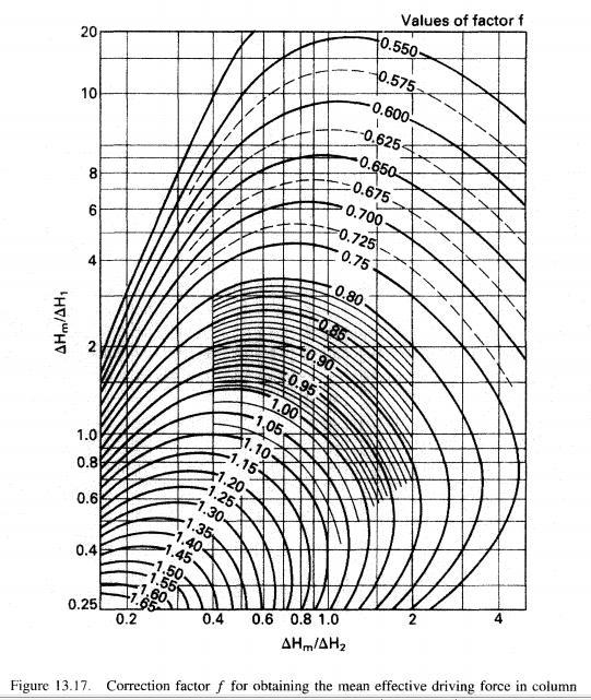
97 Calculation the height of the cooling tower: 1. Merkel and Mickley method: z = HTU * NTU G Z = D a ρ H G2 H G1 dh G H f H G a. We draw the equilibrium (saturation) curve. b. We draw the operating line. c. We draw the equilibrium line between the operating line and the saturation curve with slope = L D ρ d. We read H f and H G on the y-axis from horizontal lines drawn from the saturation curve and operating lines. e. We make a plot between H G and represent's (NTU). 1 H f H G and find the area under the curve which 97
98 2. Carey and Williamson method: G Z = D a ρ. H G2 H G1 f H m. ( ) Where: H m is the enthalpy difference at the mean water temperature in the column. and, the mean temperature is, θ m = θ L1+θ L2 2 f is a factor for converting the driving force at the mean water temperature to the effective value. How to gain H m : H 1 = H f1 H G1 H 2 = H f2 H G2 at the bottom of the column at the top of the column θ m = θ L1 + θ L2 2 At θ m we find H fm and H Gm : θ m = θ L1+θ L2 2 H m = H fm H Gm So we have: H m H 1 and H m H 2 Then from figure (13.17 ) we find f, then we can use the equation (*) to calculate the height of cooling tower (Z): 98
99 99
Mass Transfer Operations I Prof. Bishnupada Mandal Department of Chemical Engineering Indian Institute of Technology, Guwahati
 Mass Transfer Operations I Prof. Bishnupada Mandal Department of Chemical Engineering Indian Institute of Technology, Guwahati Module - 5 Distillation Lecture - 5 Fractional Distillation Welcome to the
Distillation. This is often given as the definition of relative volatility, it can be calculated directly from vapor-liquid equilibrium data.
 Distillation Distillation may be defined as the separation of the components of a liquid mixture by a process involving partial vaporization. The vapor evolved is usually recovered by condensation. Volatility
Mass Transfer Operations I Prof. Bishnupada Mandal Department of Chemical Engineering Indian Institute of Technology, Guwahati
 Mass Transfer Operations I Prof. Bishnupada Mandal Department of Chemical Engineering Indian Institute of Technology, Guwahati Module - 5 Distillation Lecture - 6 Fractional Distillation: McCabe Thiele
MODULE 5: DISTILLATION
 MOULE 5: ISTILLATION LECTURE NO. 3 5.2.2. Continuous distillation columns In contrast, continuous columns process a continuous feed stream. No interruptions occur unless there is a problem with the column
Distillation is a method of separating mixtures based
 Distillation Distillation is a method of separating mixtures based on differences in their volatilities in a boiling liquid mixture. Distillation is a unit operation, or a physical separation process,
Mass Transfer Operations I Prof. BishnupadaMandal Department of Chemical Engineering Indian Institute of Technology, Guwahati
 Mass Transfer Operations I Prof. BishnupadaMandal Department of Chemical Engineering Indian Institute of Technology, Guwahati Module -5 Distillation Lecture - 8 Fractional Distillation: Subcooled Reflux,
Vapor-liquid Separation Process MULTICOMPONENT DISTILLATION
 Vapor-liquid Separation Process MULTICOMPONENT DISTILLATION Outline: Introduction to multicomponent distillation Phase Equilibria in Multicomponent Distillation (Pg. 737) Bubble-point and dew-point calculation
ERT 313 BIOSEPARATION ENGINEERING EXTRACTION. Prepared by: Miss Hairul Nazirah Abdul Halim
 ERT 313 BIOSEPARATION ENGINEERING EXTRACTION Prepared by: Miss Hairul Nazirah Abdul Halim Definition of Extraction Liquid-Liquid extraction is a mass transfer operation in which a liquid solution (the
All Rights Reserved. Armando B. Corripio, PhD, P.E., Multicomponent Distillation Column Specifications... 2
 Multicomponent Distillation All Rights Reserved. Armando B. Corripio, PhD, P.E., 2013 Contents Multicomponent Distillation... 1 1 Column Specifications... 2 1.1 Key Components and Sequencing Columns...
Chapter 4: Column Distillation: Internal Stage-by-Stage Balances
 Chapter 4: Column Distillation: Internal Stage-by-Stage Balances In Chapter 3 (Introduction to Column Distillation), we performed the external balances or the balances around the distillation column To
All rights reserved. Armando B. Corripio, PhD, PE Flash Distillation Flash Drum Variables and Specifications... 2
 Flash Distillation All rights reserved. Armando B. Corripio, PhD, PE. 2013 Contents Flash Distillation... 1 1 Flash Drum Variables and Specifications... 2 2 Flash Drum Balances and Equations... 4 2.1 Equilibrium
McCabe Thiele Graphical Equilibrium-Stage
 Limiting condition McCabe Thiele Graphical Equilibrium-Stage When analzing or designing a process, it is useful to look at limiting cases to assess the possible values of process parameters. In distillation
An Efficient Design of Multi Component Distillation Column by Approximate & Rigorous Method
 An Efficient Design of Multi Component Distillation Column by Approximate & Rigorous Method Syed Mujahed Ali Rizwan Senior Lecturer in Chemistry Challenger College, Moinabad, Hyderabad. Abstract: In this
EXTENDED SMOKER S EQUATION FOR CALCULATING NUMBER OF STAGES IN DISTILLATION
 EXTENDED SMOKER S EQUATION FOR CALCULATING NUMBER OF STAGES IN DISTILLATION Santanu Bandyopadhyay Energy Systems Engineering and Department of Mechanical Engineering, Indian Institute of Technology, Bombay,
Problem Appendix Antoine constants Important properties of unordered packings... 22
 Contents Sample problems and eercises Distillation... 3 Sample problems... 3 Sample : Calculating vapor phase composition for immiscible liquids... 3 Sample 2: Calculating boiling point and vapor phase
Cryogenic Engineering Prof. M. D. Atrey Department of Mechanical Engineering Indian Institute of Technology, Bombay. Lecture No. #23 Gas Separation
 Cryogenic Engineering Prof. M. D. Atrey Department of Mechanical Engineering Indian Institute of Technology, Bombay Lecture No. #23 Gas Separation So, welcome to the 23rd lecture, on Cryogenic Engineering,
See section and the dew and bubble point calculations in example 11.9.
 Solution 1.1 See section 11.3.2 and the dew and bubble point calculations in example 11.9. This type of problem is best solved using a spread-sheet, see the solution to problem 11.2. Solution 11.2 This
Computer Aided Design Module for a Binary Distillation Column
 Computer Aided Design Module for a Binary Distillation Column K. R. Onifade Department of Chemical Engineering, Federal University of Technology Minna, Nigeria Abstract A Computer Aided Design (CAD) module
INDUSTRIAL EXPERIENCE WITH HYBRID DISTILLATION PERVAPORATION OR VAPOR PERMEATION APPLICATIONS
 INDUSTRIAL EXPERIENCE WITH HYBRID DISTILLATION PERVAPORATION OR VAPOR PERMEATION APPLICATIONS Mario Roza, Eva Maus Sulzer Chemtech AG, Winterthur, Switzerland; E-mails: mario.roza@sulzer.com, eva.maus@sulzer.com
MODULE 5: DISTILLATION
 MODULE 5: DISTILLATION LECTURE NO. 5 Determination of the stripping section operating line (SOL): The stripping section operating line (SOL) can be obtained from the ROL and q- line without doing any material
DISTILLATION. Keywords: Phase Equilibrium, Isothermal Flash, Adiabatic Flash, Batch Distillation
 25 DISTILLATION Keywords: Phase Equilibrium, Isothermal Flash, Adiabatic Flash, Batch Distillation Distillation refers to the physical separation of a mixture into two or more fractions that have different
Introduction: Introduction. material is transferred from one phase (gas, liquid, or solid) into another.
 into another.") Introduction: Virtually all commercial chemical processes involve operations in which material is transferred from one phase (gas, liquid, or solid) into another. rewing a cup of Coffee (Leaching) Removal
Introduction: Virtually all commercial chemical processes involve operations in which material is transferred from one phase (gas, liquid, or solid) into another. rewing a cup of Coffee (Leaching) Removal
L/O/G/O 單元操作 ( 三 ) Chapter 21 Distillation 化學工程系李玉郎
 Chapter 21 Distillation 化學工程系李玉郎") /O/G/O 單元操作 ( 三 ) Chapter 21 istillation 化學工程系李玉郎 ifferent methods: Batch: Single stage without reflu -- Simple dist. Multi-stage with reflu Continuous: Single stage without reflu--flash dist. Multi-stage
/O/G/O 單元操作 ( 三 ) Chapter 21 istillation 化學工程系李玉郎 ifferent methods: Batch: Single stage without reflu -- Simple dist. Multi-stage with reflu Continuous: Single stage without reflu--flash dist. Multi-stage
Principles of Food and Bioprocess Engineering (FS 231) Solutions to Example Problems on Psychrometrics
 Solutions to Example Problems on Psychrometrics") Principles of Food and Bioprocess Engineering (FS 21) Solutions to Example Problems on Psychrometrics 1. We begin by identifying the conditions of the two streams on the psychrometric chart as follows.
Principles of Food and Bioprocess Engineering (FS 21) Solutions to Example Problems on Psychrometrics 1. We begin by identifying the conditions of the two streams on the psychrometric chart as follows.
Processes and Process Variables
 FACULTY OF PETROLEUM & RENEWABLE ENERGY ENGINEERING Course Learning Outcomes Chapter 2 Processes and Process Variables At the end of this course students will be able to Calculate the composition in term
CL-333 Manual. MT 303: Batch Distillation
 CL-333 Manual MT 303: Batch Distillation Batch Distillation Equipment Operating Panel Refrectometer 1 CL-333 Manual MT 303: Batch Distillation Objectives: To determine the height equivalent to number of
Absorption/Stripping
 Absorption/Stripping Gas-liquid separation processes (Ch. 10) Cooling (condenser) Feed A+B Distillation(Ch.11) Absorption (Ch.10) Stripping (Ch.10) B COUNTER-CURRENT MULTISTAGE CONTACT OF GAS AND LIQUID
Physicochemical Processes
 Lecture 3 Physicochemical Processes Physicochemical Processes Air stripping Carbon adsorption Steam stripping Chemical oxidation Supercritical fluids Membrane processes 1 1. Air Stripping A mass transfer
Distillation. Senior Design CHE 396 Andreas Linninger. Innovative Solutions. Michael Redel Alycia Novoa Tanya Goldina Michelle Englert
 Distillation Senior Design CHE 396 Andreas Linninger Innovative Solutions Michael Redel Alycia Novoa Tanya Goldina Michelle Englert Table of Contents Introduction 3 Flowsheet 4 Limitations 5 Applicability
Processes and Process Variables
 FACULTY OF CHEMICAL & ENERGY ENGINEERING www.utm.my/petroleum Faculty of Petroleum & Renewable Energy Chapter 2 Processes and Process Variables Sem I (2013/14) 1 Course Learning Outcomes At the end of
WINTER-15 EXAMINATION Model Answer
 Subject code :(735) Page of 9 Important Instructions to examiners: ) The answers should be examined by key words and not as word-to-word as given in the model answer scheme. ) The model answer and the
Distillation of Liquids: Separation of 2-Propanol from Water by Fractional Distillation
 Distillation of Liquids: Separation of 2-Propanol from Water by Fractional Distillation Introduction: Distillation is the process of vaporizing a liquid, condensing the vapor, and collecting the condensate
Distilla l tion n C olum u n
 Distillation Column Distillation: Process in which a liquid or vapour mixture of two or more substances is separated into its component fractions of desired purity, by the application and removal of heat
Distillation Course MSO2015
 Distillation Course MSO2015 Distillation Distillation is a process in which a liquid or vapour mixture of two or more substances is separated into its component fractions of desired purity, by the application
Subject : Chemistry Class : XII Chapter-2.Solutions Work Sheet ( WS 2. 1) Topic- 2.1 Henry s & Raoult s Laws
 Topic- 2.1 Henry s & Raoult s Laws") Work Sheet ( WS 2. 1) Topic- 2.1 Henry s & Raoult s Laws Name -. Class/ sec.. Roll No.. A. Fill in the blanks: 1. Solutions are mixtures of two or more than two components. 2. Generally, the component
Work Sheet ( WS 2. 1) Topic- 2.1 Henry s & Raoult s Laws Name -. Class/ sec.. Roll No.. A. Fill in the blanks: 1. Solutions are mixtures of two or more than two components. 2. Generally, the component
EXPERIMENT 7 - Distillation Separation of a Mixture
 EXPERIMENT 7 - Distillation Separation of a Mixture Purpose: a) To purify a compound by separating it from a non-volatile or less-volatile material. b) To separate a mixture of two miscible liquids (liquids
Reflections on the use of the McCabe and Thiele method
 From the Selectedorks of João F Gomes January 2007 Reflections on the use of the McCabe and Thiele method Contact Author Start Your Own Selectedorks Notify Me of New ork Available at: http://works.bepress.com/joao_gomes/42
Azeotropic distillation Example 1
 Azeotropic distillation Example 1 Separate water from iso-butanol. The phase behavior for this mixture is interesting. There is a minimum boiling azeotrope formed as well as a liquid-liquid phase separation
Process Classification
 Process Classification Before writing a material balance (MB) you must first identify the type of process in question. Batch no material (mass) is transferred into or out of the system over the time period
Shortcut Distillation. Agung Ari Wibowo, S.T., M.Sc Politeknik Negeri Malang Malang - Indonesia
 Shortcut Distillation Agung Ari Wibowo, S.T., M.Sc Politeknik Negeri Malang Malang - Indonesia The use of separation column in HYSYS The column utilities in HYSYS can be used to model a wide variety of
Energy and Energy Balances
 Energy and Energy Balances help us account for the total energy required for a process to run Minimizing wasted energy is crucial in Energy, like mass, is. This is the Components of Total Energy energy
Outline of the Course
 Outline of the Course 1) Review and Definitions 2) Molecules and their Energies 3) 1 st Law of Thermodynamics Conservation of Energy. 4) 2 nd Law of Thermodynamics Ever-Increasing Entropy. 5) Gibbs Free
SUMMER-18 EXAMINATION Model Answer
 (ISO/IEC - 700-005 Certified) SUMMER-8 EXAMINATION Subject Title: Stoichiometry Subject code : 735 Page of 7 Important Instructions to examiners: ) The answers should be examined by key words and not as
Phase Separation Degree of Freedom Analysis. Binary Vapor-Liquid Systems. Azeotropic Systems. - Gibbs phase rule F C P 2 -General analysis
 Lecture 5. Single Equilibrium Stages (1) Phase Separation [Ch. 4] Degree of Freedom Analysis - Gibbs phase rule F CP2 -General analysis Binary Vapor-Liquid Systems - Examples of binary system - Phase equilibrium
General Separation Techniques
 ecture 2. Basic Separation Concepts (1) [Ch. 1] General Separation Techniques - Separation by phase creation - Separation by phase addition - Separation by barrier - Separation by solid agent - Separation
(Refer Slide Time: 00:00:43 min) Welcome back in the last few lectures we discussed compression refrigeration systems.
 Welcome back in the last few lectures we discussed compression refrigeration systems.") Refrigeration and Air Conditioning Prof. M. Ramgopal Department of Mechanical Engineering Indian Institute of Technology, Kharagpur Lecture No. # 14 Vapour Absorption Refrigeration Systems (Refer Slide
Refrigeration and Air Conditioning Prof. M. Ramgopal Department of Mechanical Engineering Indian Institute of Technology, Kharagpur Lecture No. # 14 Vapour Absorption Refrigeration Systems (Refer Slide
Distillation. JAMES R. FAIR Department of Chemical Engineering The University of Texas Austin, Texas. 5.1 INTRODUCTION 5.
 PART Il I N D I V I D U A L S E P A R A T I O N P R O C E S S E S C H A P T E R 5 Distillation JAMES R. FAIR Department of Chemical Engineering The University of Texas Austin, Texas 5.1 INTRODUCTION 5.M
FDE 211 Material & Energy Balances. Instructor: Dr. Ilgin Paker Yikici Fall 2015
 FDE 211 Material & Energy Balances Instructor: Dr. Ilgin Paker Yikici Fall 2015 Agenda Process classification General mass balance equation Basic functions of Processes Process Flow Diagram Degree of Freedom
01/12/2009. F. Grisafi
 Multicomponent distillation F. Grisafi 1 Introduction The problem of determining the stage and reflux requirements for multicomponent t distillations is much more complex than for binary mixtures. With
Distillation. Presented by : Nabanita Deka
 Distillation OPTIMIZATION FOR MAXIMISATION Presented by : Nabanita Deka LPG department OIL INDIA LIMITED DATED-04.03.2011 Basics of mass transfer Mass transfer : Transfer of material from one homogeneous
The most important nomenclature used in this report can be summarized in:
 Notation The most important nomenclature used in this report can be summarized in: V Vapor flow rate V T Vapor flow rate in the top L Liquid flow rate D Distillation product B Bottom product q Liquid fraction
ECH 4224L Unit Operations Lab I Thin Film Evaporator. Introduction. Objective
 Introduction In this experiment, you will use thin-film evaporator (TFE) to separate a mixture of water and ethylene glycol (EG). In a TFE a mixture of two fluids runs down a heated inner wall of a cylindrical
EVAPORATION YUSRON SUGIARTO
 EVAPORATION YUSRON SUGIARTO Evaporation: - Factors affecting evaporation - Evaporators - Film evaporators - Single effect and multiple effect evaporators - Mathematical problems on evaporation Principal
Shortcut Design Method for Columns Separating Azeotropic Mixtures
 3908 Ind. Eng. Chem. Res. 2004, 43, 3908-3923 Shortcut Design Method for Columns Separating Azeotropic Mixtures Guilian Liu, Megan Jobson,*, Robin Smith, and Oliver M. Wahnschafft Department of Process
Comprehend and execute the 10 elements of effective problem
 Lecture 8, 3/9/2012 Chapter 7: A GENERAL Strategy for Solving Material Balance Problems Objectives: Comprehend and execute the 10 elements of effective problem Drive a flow chart and Place labels on the
LATEST TECHNOLOGY IN Safe handling & Recovery OF Solvents in Pharma Industry
 LATEST TECHNOLOGY IN Safe handling & Recovery OF Solvents in Pharma Industry TYPICAL SOLVENT USE IN Pharma Industry Usage of solvents in an API process development is for: Diluent to carry out reaction
CHEMISTRY Topic #2: Thermochemistry and Electrochemistry What Makes Reactions Go? Fall 2018 Dr. Susan Findlay See Exercises in Topic 8
 CHEMISTRY 2000 Topic #2: Thermochemistry and Electrochemistry What Makes Reactions Go? Fall 208 Dr. Susan Findlay See Exercises in Topic 8 Vapour Pressure of Pure Substances When you leave wet dishes on
Chapter 3 PROPERTIES OF PURE SUBSTANCES. Thermodynamics: An Engineering Approach, 6 th Edition Yunus A. Cengel, Michael A. Boles McGraw-Hill, 2008
 Chapter 3 PROPERTIES OF PURE SUBSTANCES Thermodynamics: An Engineering Approach, 6 th Edition Yunus A. Cengel, Michael A. Boles McGraw-Hill, 2008 Objectives Introduce the concept of a pure substance. Discuss
Chapter 2 Equilibria, Bubble Points, Dewpoints, Flash Calculations, and Activity Coefficients
 Chapter 2 Equilibria, Bubble Points, Dewpoints, Flash Calculations, and Activity Coefficients 2.1 Vapour Pressure Calculations The basis for all phase equilibrium calculations are the vapour pressures
Chapter 3 PROPERTIES OF PURE SUBSTANCES
 Thermodynamics: An Engineering Approach Seventh Edition Yunus A. Cengel, Michael A. Boles McGraw-Hill, 2011 Chapter 3 PROPERTIES OF PURE SUBSTANCES Copyright The McGraw-Hill Companies, Inc. Permission
Part I.
 Part I bblee@unimp . Introduction to Mass Transfer and Diffusion 2. Molecular Diffusion in Gasses 3. Molecular Diffusion in Liquids Part I 4. Molecular Diffusion in Biological Solutions and Gels 5. Molecular
The two major assumptions required to reduce VLE calculations to Raoult's law are:
 10.4 SIMPLE MODELS FOR VAPOR/LIQUID EQUILIBRIUM The preceding section has described what is observed through experimental observation. When thermodynamics is applied to vapour/liquid equilibrium, the goal
[Thirumalesh*, 4.(8): August, 2015] ISSN: (I2OR), Publication Impact Factor: 3.785
![[Thirumalesh*, 4.(8): August, 2015] ISSN: (I2OR), Publication Impact Factor: 3.785](/thumbs/72/66727861.jpg "[Thirumalesh*, 4.(8): August, 2015] ISSN: (I2OR), Publication Impact Factor: 3.785") IJESRT INTERNATIONAL JOURNAL OF ENGINEERING SCIENCES & RESEARCH TECHNOLOGY CASE STUDY ON MULTICOMPONENT DISTILLATION AND DISTILLATION COLUMN SEQUENCING Thirumalesh. B.S*, Ramesh.V * Assistant Professor
IJESRT INTERNATIONAL JOURNAL OF ENGINEERING SCIENCES & RESEARCH TECHNOLOGY CASE STUDY ON MULTICOMPONENT DISTILLATION AND DISTILLATION COLUMN SEQUENCING Thirumalesh. B.S*, Ramesh.V * Assistant Professor
Chapter 3 PROPERTIES OF PURE SUBSTANCES
 Chapter 3 PROPERTIES OF PURE SUBSTANCES PURE SUBSTANCE Pure substance: A substance that has a fixed chemical composition throughout. Air is a mixture of several gases, but it is considered to be a pure
PRINCIPLES AND MODERN APPLICATIONS OF MASS TRANSFER OPERATIONS
 PRINCIPLES AND MODERN APPLICATIONS OF MASS TRANSFER OPERATIONS Jaime Benitez iwiley- INTERSCIENCE A JOHN WILEY & SONS, INC., PUBLICATION Preface Nomenclature xiii xv 1. FUNDAMENTALS OF MASS TRANSFER 1
They provide us with the knowledge of phase composition and phase stability as a function of temperature (T), pressure (P) and composition(c).
, pressure (P) and composition(c).") They provide us with the knowledge of phase composition and phase stability as a function of temperature (T), pressure (P) and composition(c). PHASE EQUILIBRIUM one of the most important sources of information
They provide us with the knowledge of phase composition and phase stability as a function of temperature (T), pressure (P) and composition(c). PHASE EQUILIBRIUM one of the most important sources of information
R13 SET - 1 '' ''' '' ' '''' Code No RT21033
 SET - 1 II B. Tech I Semester Supplementary Examinations, June - 2015 THERMODYNAMICS (Com. to ME, AE, AME) Time: 3 hours Max. Marks: 70 Note: 1. Question Paper consists of two parts (Part-A and Part-B)
Basic Thermodynamics Module 1
 Basic Thermodynamics Module 1 Lecture 9: Thermodynamic Properties of Fluids Thermodynamic Properties of fluids Most useful properties: Properties like pressure, volume and temperature which can be measured
Reminder: These notes are meant to supplement, not replace the laboratory manual. Fractional Distillation notes
 Reminder: These notes are meant to supplement, not replace the laboratory manual. Fractional Distillation notes History and Application: Fractional distillation is one of the most widely used separation
- L. _/cit ...B N - Q. - PAD"t..t... QatJ11.81L. ><"'g. Below is a blank flow diagram of a generalized distillation column: (10 Points)
") Name: February 24, 2015 EXAM 1 P a g e I 1 / e Below is a blank flow diagram of a generalized distillation column: (10 Points) f -- ' Q. - -- N - - L. PAD"t..t... QatJ11.81L _/cit...b >
Name: February 24, 2015 EXAM 1 P a g e I 1 / e Below is a blank flow diagram of a generalized distillation column: (10 Points) f -- ' Q. - -- N - - L. PAD"t..t... QatJ11.81L _/cit...b >
CHEMISTRY XL-14A PHYSICAL EQUILIBRIUM. August 13, 2011 Robert Iafe
 CHEMISTRY XL-14A PHYSICAL EQUILIBRIUM August 13, 2011 Robert Iafe Chapter Overview 2 Phases and Phase Transitions Solubility Colligative Properties Binary Liquid Mixtures Phases and Phase Transitions 3
ME 354 Tutorial, Week#13 Reacting Mixtures
 ME 354 Tutorial, Week#13 Reacting Mixtures Question 1: Determine the mole fractions of the products of combustion when octane, C 8 H 18, is burned with 200% theoretical air. Also, determine the air-fuel
Level 7 Post Graduate Diploma in Engineering Heat and mass transfer
 9210-221 Level 7 Post Graduate Diploma in Engineering Heat and mass transfer 0 You should have the following for this examination one answer book non programmable calculator pen, pencil, drawing instruments
Lecture 3: DESIGN CONSIDERATION OF DRIERS
 Lecture 3: DESIGN CONSIDERATION OF DRIERS 8. DESIGN OF DRYER Design of a rotary dryer only on the basis of fundamental principle is very difficult. Few of correlations that are available for design may
SOLUTION CONCENTRATIONS
 SOLUTION CONCENTRATIONS The amount of solute in a solution (concentration) is an important property of the solution. A dilute solution contains small quantities of solute relative to the solvent, while
Colligative Properties. Vapour pressure Boiling point Freezing point Osmotic pressure
 Colligative Properties Vapour pressure Boiling point Freezing point Osmotic pressure Learning objectives Describe meaning of colligative property Use Raoult s law to determine vapor pressure of solutions
GRAPHICAL REPRESENTATION OF THE CHANGES OF SECTOR FOR PARTICULAR CASES IN THE PONCHON SAVARIT METHOD
 GRAPICAL REPRESENTATION OF TE CANGES OF SECTOR FOR PARTICULAR CASES IN TE PONCON SAVARIT METOD J.A. REYES-LABARTA *, M.D. SERRANO and A. MARCILLA *Chemical Engng Department, University of Alicante, Apdo.
Azeotropic Distillation Methods. Dr. Stathis Skouras, Gas Processing and LNG RDI Centre Trondheim, Statoil, Norway
 Azeotropic Distillation Methods Dr. Stathis Skouras, Gas Processing and LNG RDI Centre Trondheim, Statoil, Norway Schedule Tuesday 1/12/2015: 09.45 12.30: Lecture - Natural Gas Processing 14.00 17.00:
Heterogeneous Azeotropic Distillation Operational Policies and Control
 Heterogeneous Azeotropic Distillation Operational Policies and Control Claudia J. G. Vasconcelos * and Maria Regina Wolf-Maciel State University of Campinas, School of Chemical Engineering, Campinas/SP,
Liquid-liquid extraction
 Liquid-liquid extraction Basic principles In liquid-liquid extraction, a soluble component (the solute) moves from one liquid phase to another. The two liquid phases must be either immiscible, or partially
0 o C. H vap. H evap
 Solution. Energy P (00 ) Pν x 0 5 ρ 850,4 J kg - J kg Power kg s 000,4 600 70 W Solution. 00 o C H evap H vap 0 o C H liq 00 t H liq (4. x0 t ) dt 4.t x0 0 40 0 40 kj kg - H evap 40,68 J mol - (From Appendix
 Vapour Absorption Refrigeration Systems Based On Ammonia- Water Pair Nagendra M CBM Engineer, Hindusthan Zink.Ltd The specific objectives of this lesson are to: 1. Introduce ammonia-water based vapour
An introduction to thermodynamics applied to Organic Rankine Cycles
 An introduction to thermodynamics applied to Organic Rankine Cycles By : Sylvain Quoilin PhD Student at the University of Liège November 2008 1 Definition of a few thermodynamic variables 1.1 Main thermodynamics
SEPARATION TECHNIQUES
 SEPARATION TECHNIQUES If a substance does not dissolve in a solvent, we say that it is insoluble. For example, sand does not dissolve in water it is insoluble. Filtration is a method for separating an
Available online Journal of Scientific and Engineering Research, 2018, 5(2): Research Article
: Research Article") Available online www.jsaer.com, 2018, 5(2):32-39 Research Article ISSN: 2394-2630 CODEN(USA): JSERBR A Shortcut Method for Modeling Multi-Component Distillation in an Existing Column Philomena K. Igbokwe
Available online www.jsaer.com, 2018, 5(2):32-39 Research Article ISSN: 2394-2630 CODEN(USA): JSERBR A Shortcut Method for Modeling Multi-Component Distillation in an Existing Column Philomena K. Igbokwe
Chapter 11 section 6 and Chapter 8 Sections 1-4 from Atkins
 Lecture Announce: Chapter 11 section 6 and Chapter 8 Sections 1-4 from Atkins Outline: osmotic pressure electrolyte solutions phase diagrams of mixtures Gibbs phase rule liquid-vapor distillation azeotropes
Vapor-liquid equilibrium
 Vapor-liquid equilibrium From Wikipedia, the free encyclopedia Vapor-liquid equilibrium, abbreviated as VLE by some, is a condition where a liquid and its vapor (gas phase) are in equilibrium with each
On the Synthesis of Distillation Sequences for Mixtures of Water, Hydrogen Chloride and Hydrogen Fluoride P. Pöllmann, SGL GROUP A.J.
 On the Synthesis of Distillation Sequences for Mixtures of Water, Hydrogen Chloride and Hydrogen Fluoride P. Pöllmann, SGL GROUP A.J. Gerbino, AQSim (Speaker) Problem Statement Given... An aqueous feed
Theory. Humidity h of an air-vapor mixture is defined as the mass ratio of water vapor and dry air,
 Theory Background In a cooling tower with open water circulation, heat is removed from water because of the material and heat exchange between the water and the ambient air. The cooling tower is a special
Convective Heat and Mass Transfer Prof. A.W. Date Department of Mechanical Engineering Indian Institute of Technology, Bombay
 Convective Heat and Mass Transfer Prof. A.W. Date Department of Mechanical Engineering Indian Institute of Technology, Bombay Module No. # 01 Lecture No. # 32 Stefan Flow Model We are now familiar with
CH2351 Chemical Engineering Thermodynamics II Unit I, II Phase Equilibria. Dr. M. Subramanian
 CH2351 Chemical Engineering Thermodynamics II Unit I, II Phase Equilibria Dr. M. Subramanian Associate Professor Department of Chemical Engineering Sri Sivasubramaniya Nadar College of Engineering Kalavakkam
Batch system example (previous midterm question)
") Batch system example (previous midterm question) You are to design a batch adsorber to remove an organic contaminant (A) from 400L of aqueous solution containing 0.05g/L of the contaminant. To facilitate
Batch system example (previous midterm question) You are to design a batch adsorber to remove an organic contaminant (A) from 400L of aqueous solution containing 0.05g/L of the contaminant. To facilitate
The temp. at which a liquid distills is a definite value at a given pressure, for every pure organic cpd called boiling point.
 Distillation It is a process of separation & purification of liquid organic cpd.s by selective evaporation & condensation. It may result in complete separation ( nearly pure ), or,a partial separation
Examples Solid-Liquid Extraction
 Examples Solid - Liquid Extraction Lecturer: Dr.Gamse - - Examples Solid-Liquid Extraction. Rectangular Triangle Diagram C A... inert material B... extractable material C... solvent Y C / (A + B + C) F
Chapter Solutions. MockTime.com. (a) M urea (b) 0.01 M KNO3 (c) 0.01 M Na2 SO4 (d) M glucose Ans: (c)
 M urea (b) 0.01 M KNO3 (c) 0.01 M Na2 SO4 (d) M glucose Ans: (c)") 47 Chapter Solutions 1. Freezing point of an aqueous solution is ( 0.186) C. Elevation of boiling point of the same solution is K b = 0.512 C,Kf = 1.86 C, find the increase in boiling point. [2002] (a)
47 Chapter Solutions 1. Freezing point of an aqueous solution is ( 0.186) C. Elevation of boiling point of the same solution is K b = 0.512 C,Kf = 1.86 C, find the increase in boiling point. [2002] (a)
Mass Transfer Operations I Prof. Bishnupada Mandal Department of Chemical Engineering Indian Institute of Technology, Guwahati
 Mass Transfer Operations I Prof. Bishnupada Mandal Department of Chemical Engineering Indian Institute of Technology, Guwahati Module - 4 Absorption Lecture - 3 Packed Tower Design Part 2 (Refer Slide
12. Heat of melting and evaporation of water
 VS 12. Heat of melting and evaporation of water 12.1 Introduction The change of the physical state of a substance in general requires the absorption or release of heat. In this case, one speaks of a first
Analysis of Performance of Packed Columns
 Analysis of Performance of Packed Columns There are two packed column experiments in the Unit Operations lab: Liquid-Liquid Extraction (LLE) and Gas Absorption (GA). In both of these experiments, a solute
AE 205 Materials and Energy Balances Asst. Prof. Dr. Tippabust Eksangsri. Chapter 6 Energy Balances on Chemical Processes
 AE 205 Materials and Energy Balances Asst. Prof. Dr. Tippabust Eksangsri Chapter 6 Energy Balances on Chemical Processes Thermodynamics system surroundings system boundary Forms of Energy 1. Energy Possessed
Distillation. Sep-tek. Ch.11 (continued) Distillation (Multistage with reflux) Sigurd Skogestad. Separation of liquid mixtures by repeated evaporation
 Distillation (Multistage with reflux) Sigurd Skogestad. Separation of liquid mixtures by repeated evaporation") Sep-tek. Ch.11 (continued) Distillation (Multistage with reflux) Sigurd Skogestad Distillation Separation of liquid mixtures by repeated evaporation multi-stage with reflux Old name: Rectification Basis:
Sep-tek. Ch.11 (continued) Distillation (Multistage with reflux) Sigurd Skogestad Distillation Separation of liquid mixtures by repeated evaporation multi-stage with reflux Old name: Rectification Basis: