Resistance : R = ρ( ) units are Ohms ( 14 ) Resistor 100 ohms
|
|
|
- Brent Miller
- 5 years ago
- Views:
Transcription
1 Resistance : If we look a little more closely into how charge flows in a conductor, we see that the electron is essentially free to move about the metal conductor material. The electron roams about the conductor, dropping in and out of various valance shells of the metal atoms or wanders between the atoms. Note, as the electron moves about and eventually hits another metal lattice atom and absorbed into its valence shell, it will give up some of its energy in the form of heat. Since no voltage has been applied to the conductor the process will be totally random with no total electron flow in any one direction. Under these conditions, the current is said to be zero. In summary, when a free electron hits a lattice atom, energy is lost as heat and the electron winds up in the valence shell. So the lattice atom in a sense offers a resistance to the flow of charge or free movement of the electron about the conductor material. The conductor material that exhibits this property is then said to be resistive. Components that are designed to offer varying degrees of resistance to the flow of charge are called Resistors. The electrical symbol used for a Resistor is shown in fig. 14. Resistor 100 ohms R1 100Ω Fig. 16 Even though conductors have been discussed here, it can be said that the resistance is essentially a function of the material used. So this resistance can apply to any material in general that includes semiconductors and insulators. The semiconductor can offer a very wide range of resistance going from that of metal conductor to an insulator. So the highest resistance to the flow of charge would be that of an insulator and why they are used as insulation material to cover metal conductors that need to be isolated electrically from other objects. The plastic material the covers electrical house wiring would be an example of that. The resistance of a metallic conductor is directly proportional to the length of the conductor and inversely proportional to its crosssectional area. Therefore the resistance of a specific type of conductor material would be a function of what was just stated and the type of material used, called its resistivity ( ρ ). Stated in equation form, R = ρ( ) units are Ohms ( 14 ) The terms ρ is the Resistivity of the material in OhmMeters, L is the length in Meters and A the crosssectional area in square Meters. Note, the Resistivity is a physical property of the material which is dependent on temperature. The table in Figure 17 list the Resistivity of some typical materials ranging from metals to insulators. In Figure 18 is a scale drawing comparing some solid wire sizes with reference to their wire gage number (AWG) and a end view of a segment of stranded wire. Note in this case the

in one direction.")
2 stranded wire is made up of seven smaller gage solid wire segments that are twisted around a central wire, all making electrical contact where each wire touches each other. Fig. 17 Fig. 18 Looking at equation 14 it is noted that the resistance is proportional to the length of a conductor. So as the conductor gets longer with the area remaining constant, its resistance goes up. Does this make sense? The answer is yes. In order to investigate this further lets first apply a voltage across both ends of a metal conductor. This applied voltage will then apply a force to the charge in that conductor forcing the charge to drift ( flow )in one direction. This defines the current in this conductor and its numeric value is determined by how difficult it is for the charge make its way through the conductor. Remember the conductor lattice atoms present targets for the electron (charge) to hit thus slowing down the progress of the electron traveling through the conductor. Now if the length (L) of the conductor Fig. 19 was doubled (2L) Fig. 20, area remaining constant, the difficulty to travel down the conductor would be doubled, verifying the above proportionality statement. Current Flow Electron Flow Small applied Voltage The ions are part of the lattice and are fixed targets. L Note the difficulty the electron has moving through the lattice without hitting a ion lattice atom. So the metal lattice atoms resist the flow of electrons and why it is important we know the materials resistance to the flow of electrons. Fig. 19
3 Current Flow Electron Flow Small applied Voltage The ions are part of the lattice and are fixed targets. Note the difficulty the electron has moving through the lattice without hitting a ion lattice atom. So the metal lattice atoms resist the flow of electrons and why it is important we know the materials resistance to the flow of electrons. 2L Fig. 20 The resistance is also inversely proportional to the crosssectional area of the conductor. If the wire diameter gets wider the crosssectional area will get larger making it much easier for the electrons to move between the lattice atoms. Since the electrons are no longer confined to a narrow crosssectional area it has a better chance of moving between the lattice atoms lowering its resistance to flow through the wire. Electron Flow L The ions are part of the lattice and are fixed targets. D Area = A Current Flow Small applied Voltage JOR Fig. 21 For example, in figure 21 above, the electrons free path before a collision with a lattice atom is about one quarter that of the conductor in figure 22. Looking at that from another point of view. It can also be said that the free path of the electron before a collision with a lattice atom in figure 22 is four times that of the conductor in figure 21. In figure 21, Area = A = ( )(r 2 ) = ( )( ) 2 ( 15 )
4 R 1 = ρ( ) = ρ( ) = 4( ) for wire diameter = D ( 16 ) Current Flow Electron Flow L The ions are part of the lattice and are fixed targets. Small applied Voltage 2D Area = 2A JOR Fig. 22 R 2 = ρ( ) = ρ( ) = 4( ) = ( ) for wire diameter = 2D ( 17 ) R 2 = R 1 ( 18 ) This result says the wire with twice the diameter (2D) has one quarter the resistance as the shorter diameter (D) wire. In summary, for a fixed diameter wire, the resistance goes up proportionally as the wire length increases. Given a fixed length wire, the resistance goes down as the diameter increases. Remember in this case the resistance is inversely proportional to the crosssectional area, not the diameter directly. What does all this mean? It means that the longer the electron is free in a conductor the lesser the resistance to its flow. This effectively means its resistance is smaller than a conductor that has a shorter electron free path. The Practical Calculation of Resistance : The resistance of any material with a uniform crosssectional area maybe determined by the following four factors : 1. Length. 2. Type of Material. 3. Its Temperature. 4. Its crosssectional area.
5 For a fixed temperature of 20 0 C, the Resistance may be expressed as, R = ρ( ) ( 19 ) Area = A = ( D Mils ) 2 = [( D in )(1000)] 2 ( 20 ) which is the same as equation 14 except all the variable now will be expressed in US Standard units not the MKS system. Here ρ is in units of (CMOhms)/Ft, A is in CM and L in feet. This concept can be a little confusing unless some effort is put into explaining it in more detail. It is important that it be understood since it is the standard used in industry for almost 100 years. The most confusing part of this concept is the Circular Mill (CM) so it will be defined more clearly below. First, the area of a circle can be expressed in terms of its diameter (D) as, Area (Circle) = r 2 = ( 21 ) Second, noting the following, 1 mil = in = 1 x 10 3 in or 1000 mils = 1 in ( 22 ) By definition : A wire with a diameter of 1 mil has an area of 1 CM (circular mil). Therefore if D= 1 mil, then, Area = A = = = sq. mils = 1 CM or 1 sq. mil = CM ( 23 ) Simply put, the area A in equation19 would be, A (CM) = ( D mils ) 2 = ( 1000*D in ) 2 ( 24 ) The following is an example problem showing why this method is so important in saving time and reducing errors. Example 1 : An engineer needs to find the resistance of 100 feet of solid Aluminum wire. Using a micrometer he determines the diameter is 0.1 inches. The first step is to look up in the table on page 7, the resistivity of Aluminum (ρ) = 17 (CMOhms)/Ft, then calculate the area directly from the square of a thousand times the micrometer reading since the standard in the U. S. is inches. A (CM) = ( D mils ) 2 = ( 1000*D in ) 2 = ( 1000*0.1 ) 2 = ( 100 ) 2 = mils
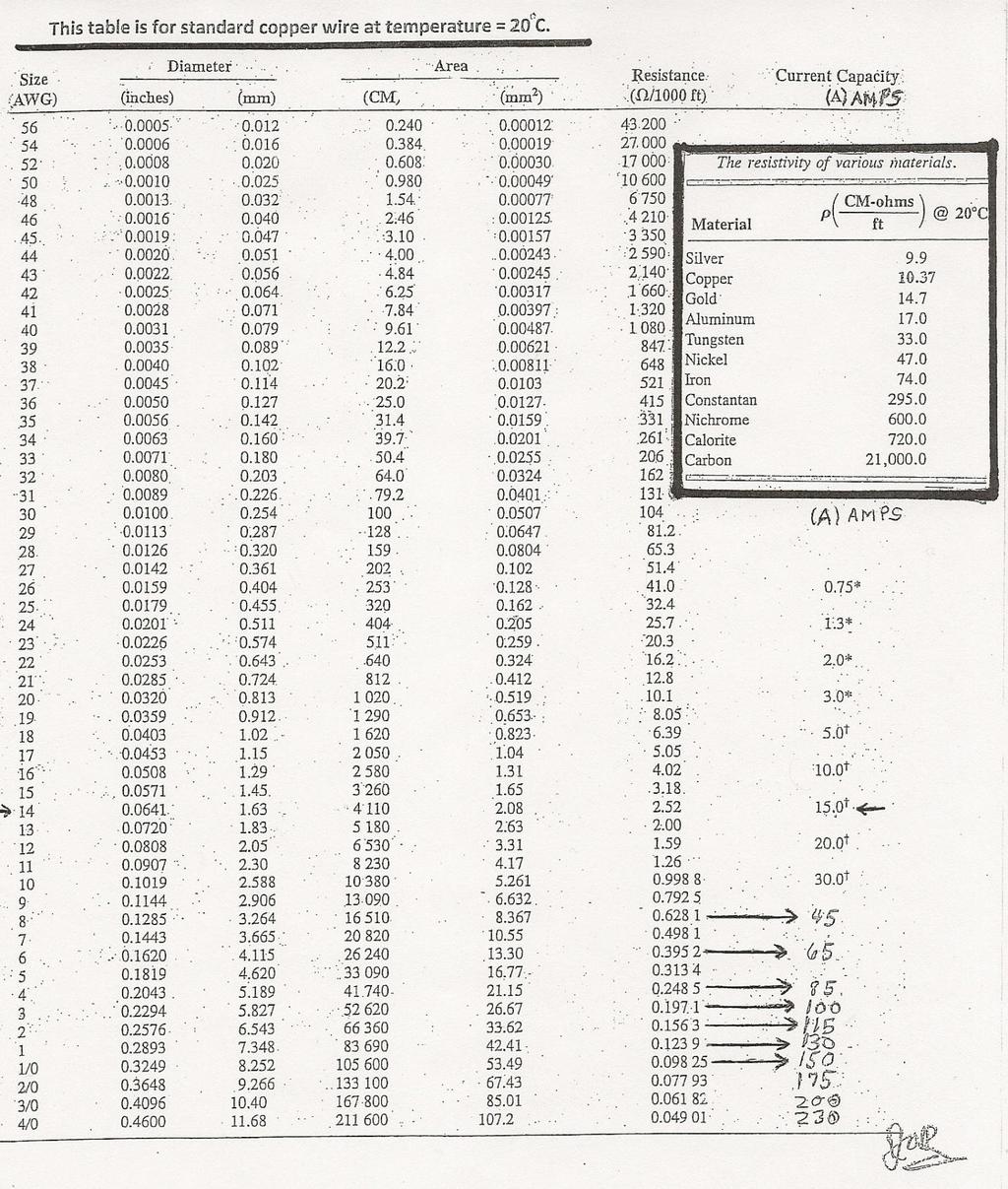
6 Substituting this area, ρ and L into equation19 yields the resistance, R = ρ( ) = (17)( ) = = 0.17 ohms So here in two simple steps the resistance is calculated and the reason it is so popular in the industry that needs this information. For a comparison the resistance will also be calculated using the MKS. Converting the diameter to meters, D = 0.1 in = (0.1in)(2.54 cm/in) = cm = 2.54 x 10 3 m Converting the length to meters, 100 ft = (12)(100) = (1200 in)(2.54 cm/in) = 3048 cm =30.48 m Defining the resistivity in MKS units, ρ = x 10 8 Ωm Calculating the area, A = = = 5.064x10 6 Finally, calculating the resistance, R = ρ( ) = ρ( ) = (2.825x10 8 )( ) = 0.17 ohms So both methods yield the same result but it is obvious that the first method is much quicker and more efficient since the area is the square of a thousand times the micrometer reading. The Table on the next page shows the wire gauge(awg), diameter, area and the current carrying capacity of various sizes of copper wire. This table is very useful since wire is purchased and identified by the AWG (wire gauge number) not its diameter. The AWG also notes the safe current carrying capacity of that size wire which is also a function of the insulation that is covering the wire in question, which is not noted in this table. A common use of this table is to look up the maximum current that would be flowing in your circuit and then pick the next size up wire gauge (AWG) which is a lower AWG. Please note, the larger the AWG number the smaller the wire and lower current carrying capacity.
7
8 Temperature effects on Resistance : The resistance of a conductor does chance with temperature. This effect is more noticeable as the applied voltage increases, the current that is flowing through the conductor increases. When both the voltage and current increase, the power dissipated in the conductor increases. This power is dissipated as heat in the conductor causing its temperature to rise. What is discovered from this effect is that the resistance of the conductor also increases an effect that is not always discussed. So in general it is important that know what the relationship between resistance and temperature looks like. This relationship is shown in the plot below. This plot shows that the resistance increases as the temperature is increased from approximately absolute zero ( T ) to temperature ( T 2 ). Note the plot in the positive temperature range is linear which allows us to find a simple analytic solution in terms of resistance and temperature. Using similar triangles, the following relation is obtained, = ( 25 ) Which yields,
 to find a R 2 at some temperature T 2 knowing the resistance ( R 1 ) at a temperature ( R 1 ).")
9 = ( ) ( 26 ) This equation yields one method which references absolute zero for its solution. Another more popular method uses the temperature coefficient of resistance ( ) to find a R 2 at some temperature T 2 knowing the resistance ( R 1 ) at a temperature ( R 1 ). R 2 = R 1 [ 1 ( T 2 T 1 )] ( 27 ) Where is the temperature coefficient of resistance for different materials. Note equation 21 does not require the need to know the absolute zero temperature of the material, just it temperature coefficient and is the more popular way to calculate R 2. The table below lists the temperature at absolute zero and the coefficient for various materials at 20 0 C. To get a better feel for the effect temperature has on resistance lets do a couple of examples. Example 1 : A Copper coil has a resistance of 10 ohms at room temperature ( 20 0 C). What would be its resistance at a temperature of C? Solution : From the table for Temp. Coeff s, = at 20 0 C. R 2 = R 1 [ 1 ( T 2 T 1 )] = 10[ (100 20)] = 10[ (80)] = 10[ ] = Ω Hence the resistance of the coil has gone up by 3.14 ohms, a little over 30% from the room temperature resistance of 10 Ω.
10 Example 2 : At what temperature would the resistance double in the example above from a given resistance of 20 ohms at 20 0 C. Solution : Solving the equation in example 1 for T 2 instead of R 2 where R 2 = 20 ohms, T 2 = [ 1] T 1 ( 28 ) T 2 = [ 1] 20 = = [ 2 1] 20 = = C Here the temperature would need to be raised to C for the resistance of the coil to double. In conclusion, it is important to understand that temperature affects the resistance of materials. How it affects the resistance depends on the materials used. The materials mentioned here all have positive temperature coefficients, meaning as the resistance goes up as the temperature goes up. Semiconductors for example have negative temperature coefficients, meaning as the resistance goes down as the temperature goes up. Also not mentioned was the effect the power dissipated in the conductor material has on its temperature. This then defines specific ratings of temperature and power dissipation that can be safely used with these materials protecting the material property from destruction. Types of resistive components and devices : The resistor that has been discussed up to this point comes in two types, fixed and variable. Fixed resistors : The resistors that are used in most everyday applications are carbon film, metal film and wire wound. These resistors are used in circuits to limit current, divide voltages or generate heat. They are available in a large selection of values that are defined by the manufacturing process. These values are consistent across the industry for specific type and tolerance. The accuracy of these fixed values is dependant on the tolerance. Some typical tolerances are 1%, 5%, 10%, 20% where 5% being most common in typical electronic circuits. The resistance value and tolerances are defined by either a color code or numeric identification on the resistor. These resistors come now in two types, component body with leads or surface mount. This type of resistor is generally low power carbon or metal film ranging in power from about 1/8 th watt to 2 watts. Power resistors are generally wire wound consisting of nickel chromium wire which is about 675 ohms per circular mil foot. So this is special resistive wire used to make the most common types of power resistors. The actual resistance value is of course a function of the area and length and/or the geometry


11 on the material making up the resistor. Another words the resistor could be a flat bar of nickel chromium material not looking at all like a typical wire wound resistor. Variable resistors : Variable resistors are designed so that their ohmic values can be easily adjusted mechanically. This resistance is varied physically by moving a metal contact wiper element over either a carbon or metal resistive deposit on a ceramic base or over single turns of resistive wire. These devices also come in a variety of precisions, power ratings and mechanical accuracy settings.


12 The standard schematic symbols for fixed and variable resistors are shown below. 1 5R2 4R3 R1 1.0kΩ 7 1.0kΩ Key=A 50% 1.0kΩ Key=A 50% Standard Fixed Resistor Symbol used in Multisim. Standard Variable Resistor Symbols used in Multisim. The symbol to the right is setup to be used as a simple in series two terminal variable resistor. Special types of resistive devices : Thermistor : The negative temperature coefficient (NTC) thermistor is essentially a semiconductor resistive device, whose resistance varies directly with temperature. This means the resistance goes down as the temperature goes up. The range of operation for different thermistors is from C to C and come in a variety of package types, glass bead, disc, probe and chip, depending on the application. The NTC type is used when a continuous change of resistance is required over a wide temperature range. The PTC types are used when it is desired to switch something on or off at some temperature usually ranging from 60 0 C to C. They are commonly used for protection of windings in transformers and electric motors.


13 Photoconductor : The photoconductor is a light sensitive resistor or sometimes called a light dependent resistor (LDR). The LDR exhibits Photoconductivity since its resistance decreases with increasing incident light intensity. The typical LDR is made from cadmium sulfide (CdS) which in the dark acts like a high resistance semiconductor. When light falls on the LDR of high enough frequency, photons will be absorbed by the CdS material giving valence band electrons enough energy to be released into the conduction band. These free electrons contribute to conduction, lowering its resistance. A typical CdS cell is shown below. There are also LRD s made of Lead Sulphide (PbS) and indium antimonide(insb) which are used to detect light in the mid infrared spectrum and Ge:Cu in the far infrared spectrum.

 : The incandescent bulb produces light by heating up a wire filament to a temperature high enough to cause the filament to glow.")

14 Flex or Strain Gauge : This unique bidirectional sensor changes its resistance when bent. The unflexed sensor has a nominal resistance ranging from 10M ohms down to 10K ohms depending on the specific device. Its lowest bent resistance could be down to 1K ohm or so. Note the bent resistance can be anywhere from meg ohms to K ohms depending on how much it is bent. The flex sensor is also pressure sensitive and can be used to sense a force applied to the sensor. Incandescent Lamp(bulb) : The incandescent bulb produces light by heating up a wire filament to a temperature high enough to cause the filament to glow. When a small voltage is applied to this filament, a current will flow. Since the filament has resistance it will initially give off energy in the form of heat. When the voltage increases, the current will also increase, causing more power to be dissipated in the filament, making it hotter. At some point as the voltage increases, the filament will get so hot that it will start to glow and give off light. This process continues until the voltage and current values reach the power rating of the filament. Once this is reached, the bulb will be at its maximum rated light output. For typical household bulbs this is defined by a wattage, like 60 watts, 100 watts etc. The filament type bulb resistance becomes nonlinear when it starts to give of light.
Chapter 03. Resistance. Resistance of Conductors. Type of Material resistivity (Ω m) Type of Material. Length / Area. Resistance Formula
 Type of Material. Length / Area. Resistance Formula") Chapter 03 Resistance Resistance of Conductors Resistance of material depends on several factors: Type of Material, Conductor length, or l Cross-sectional area, A Temperature, T C-C Source: Tsai Circuit
Chapter 03 Resistance Resistance of Conductors Resistance of material depends on several factors: Type of Material, Conductor length, or l Cross-sectional area, A Temperature, T C-C Source: Tsai Circuit
Chapter 3. Resistance. Copyright 2011 by Pearson Education, Inc. publishing as Pearson [imprint] Introductory Circuit Analysis, 12/e Boylestad
![Chapter 3. Resistance. Copyright 2011 by Pearson Education, Inc. publishing as Pearson [imprint] Introductory Circuit Analysis, 12/e Boylestad](/thumbs/92/110845929.jpg "Chapter 3. Resistance. Copyright 2011 by Pearson Education, Inc. publishing as Pearson [imprint] Introductory Circuit Analysis, 12/e Boylestad") Chapter 3 Resistance OBJECTIVES Become familiar with the parameters that determine the resistance of an element and be able to calculate the resistance from the given dimensions and material characteristics.
Chapter 3 Resistance OBJECTIVES Become familiar with the parameters that determine the resistance of an element and be able to calculate the resistance from the given dimensions and material characteristics.
Resistance Learning Outcomes
 Resistance Learning Outcomes Define resistance and give its unit. Solve problems about resistance. State Ohm s Law. HL: Derive the formulas for resistors in series and parallel. Solve problems about resistors
Resistance Learning Outcomes. Resistance Learning Outcomes. Resistance
 Resistance Learning Outcomes Define resistance and give its unit. Solve problems about resistance. State Ohm s Law. HL: Derive the formulas for resistors in series and parallel. Solve problems about resistors
SYSTEMS OF UNITS. 1 st Class Basic of Electrical Engineering. Current and Voltage
 SYSTEMS OF UNITS In the past, the systems of units most commonly used were the English and metric, as outlined in Table below. Note that while the English system is based on a single standard, the metric
EE301 RESISTANCE AND OHM S LAW
 Learning Objectives a. Describe the concept of resistance b. Use Ohm s law to calculate current, voltage, and resistance values in a circuit c. Discuss the difference between an open circuit and a short
Electric Current. Chapter 17. Electric Current, cont QUICK QUIZ Current and Resistance. Sections: 1, 3, 4, 6, 7, 9
 Electric Current Chapter 17 Current and Resistance Sections: 1, 3, 4, 6, 7, 9 Whenever electric charges of like signs move, an electric current is said to exist The current is the rate at which the charge
From this analogy you can deduce some rules that you should keep in mind during all your electronics work:
 Resistors, Volt and Current Posted on April 4, 2008, by Ibrahim KAMAL, in General electronics, tagged In this article we will study the most basic component in electronics, the resistor and its interaction
1 Written and composed by: Prof. Muhammad Ali Malik (M. Phil. Physics), Govt. Degree College, Naushera
, Govt. Degree College, Naushera") CURRENT ELECTRICITY Q # 1. What do you know about electric current? Ans. Electric Current The amount of electric charge that flows through a cross section of a conductor per unit time is known as electric
CURRENT ELECTRICITY Q # 1. What do you know about electric current? Ans. Electric Current The amount of electric charge that flows through a cross section of a conductor per unit time is known as electric
Chapter 17. Current and Resistance. Sections: 1, 3, 4, 6, 7, 9
 Chapter 17 Current and Resistance Sections: 1, 3, 4, 6, 7, 9 Equations: 2 2 1 e r q q F = k 2 e o r Q k q F E = = I R V = A L R ρ = )] ( 1 [ o o T T + = α ρ ρ V I V t Q P = = R V R I P 2 2 ) ( = = C Q
3 Electric current, resistance, energy and power
 3 3.1 Introduction Having looked at static charges, we will now look at moving charges in the form of electric current. We will examine how current passes through conductors and the nature of resistance
Closed loop of moving charges (electrons move - flow of negative charges; positive ions move - flow of positive charges. Nucleus not moving)
") Unit 2: Electricity and Magnetism Lesson 3: Simple Circuits Electric circuits transfer energy. Electrical energy is converted into light, heat, sound, mechanical work, etc. The byproduct of any circuit
Unit 2: Electricity and Magnetism Lesson 3: Simple Circuits Electric circuits transfer energy. Electrical energy is converted into light, heat, sound, mechanical work, etc. The byproduct of any circuit
ELEC 103. Objectives
 ELEC 103 Voltage, Current, and Resistance Objectives Define voltage and discuss its characteristics Define current and discuss its characteristics Define resistance and discuss its characteristics Identify
Direct Currents. We will now start to consider charges that are moving through a circuit, currents. Sunday, February 16, 2014
 Direct Currents We will now start to consider charges that are moving through a circuit, currents. 1 Direct Current Current usually consists of mobile electrons traveling in conducting materials Direct
Current and Resistance
 PHYS102 Previous Exam Problems CHAPTER 26 Current and Resistance Charge, current, and current density Ohm s law Resistance Power Resistance & temperature 1. A current of 0.300 A is passed through a lamp
T h e rm i s t o r s
 Data Pack E Issued March 00 - T h e rm i s t o r s NTC thermistors The R S range of NTC thermistors includes standard tolerance negative temperature coefficient thermistors, a range of small close tolerance
What is dynamic electricity?
 Dynamic Electricity What is dynamic electricity? Has to do with charges in motion So we re talking about moving electrons Think about any electronic device Dynamic electricity Think back to properties
Electric Fields. Basic Concepts of Electricity. Ohm s Law. n An electric field applies a force to a charge. n Charges move if they are mobile
 Basic Concepts of Electricity oltage E Current I Ohm s Law Resistance R E = I R Electric Fields An electric field applies a force to a charge Force on positive charge is in direction of electric field,
5. ELECTRIC CURRENTS
 5. ELECTRIC CURRENTS TOPIC OUTLINE Section Recommended Time Giancoli Section 5.1 Potential Difference, Current, Resistance 5.2 Electric Circuits 3h 19.1, 19.2 6.2 Electric Field and Force 6.3 Magnetic
Electron Theory. Elements of an Atom
 Electron Theory Elements of an Atom All matter is composed of molecules which are made up of a combination of atoms. Atoms have a nucleus with electrons orbiting around it. The nucleus is composed of protons
An Introduction to Electricity and Circuits
 An Introduction to Electricity and Circuits Materials prepared by Daniel Duke 4 th Sept 2013. This document may be copied and edited freely with attribution. This course has been designed to introduce
Part 2. Sensor and Transducer Instrument Selection Criteria (3 Hour)
") Part 2 Sensor and Transducer Instrument Selection Criteria (3 Hour) At the end of this chapter, you should be able to: Describe the definition of sensor and transducer Determine the specification of control
Part 2 Sensor and Transducer Instrument Selection Criteria (3 Hour) At the end of this chapter, you should be able to: Describe the definition of sensor and transducer Determine the specification of control
You should be able to demonstrate and show your understanding of:
 OCR B Physics H557 Module 3: Physics in Action You should be able to demonstrate and show your understanding of: 3.1: Communication 3.1.1: Imaging and Signalling The formation of a real image by a thin
Unit 2. Current, Voltage and Resistance
 Strand G. Electricity Unit 2. Current, Voltage and Resistance Contents Page Current 2 Potential Difference, Electromotive Force and Power 5 Resistance and Ohm s Law 9 G.2.1. Current In a metallic conductor
CEE575 - Homework 1. Resistive Sensing: Due Monday, January 29
 CEE575 - Homework 1 Resistive Sensing: Due Monday, January 29 Problem 1: Planes A metallic wire embedded in a strain gage is 4 cm long with a diameter of 0.1 mm. The gage is mounted on the upper surface
Current and Resistance
 Current and Resistance 1 Define the current. Understand the microscopic description of current. Discuss the rat at which the power transfer to a device in an electric current. 2 2-1 Electric current 2-2
ECNG3032 Control and Instrumentation I
 sensor ECNG3032 Control and Instrumentation I Lecture 1 Temperature Sensors Sensors The sensor is the first element in the measurement system. Measurand Transducer Principle Excitation Signal Interface
Electricity Review completed.notebook. June 13, 2013
 Which particle in an atom has no electric charge associated with it? a. proton c. neutron b. electron d. nucleus Jun 12 9:28 PM The electrons in a metal sphere can be made to move by touching it with a
Resistivity and Temperature Coefficients (at 20 C)
") Homework # 4 Resistivity and Temperature Coefficients (at 0 C) Substance Resistivity, Temperature ( m) Coefficient, (C ) - Conductors Silver.59 x 0-0.006 Copper.6 x 0-0.006 Aluminum.65 x 0-0.0049 Tungsten
Homework # 4 Resistivity and Temperature Coefficients (at 0 C) Substance Resistivity, Temperature ( m) Coefficient, (C ) - Conductors Silver.59 x 0-0.006 Copper.6 x 0-0.006 Aluminum.65 x 0-0.0049 Tungsten
Section 1 Electric Charge and Force
 CHAPTER OUTLINE Section 1 Electric Charge and Force Key Idea questions > What are the different kinds of electric charge? > How do materials become charged when rubbed together? > What force is responsible
Downloaded from
 CHAPTER 12 ELECTRICITY Electricity is a general term that encompasses a variety of phenomena resulting from the presence and flow of electric charge. These include many easily recognizable phenomena such
Chapter 2. Chapter 2
 Chapter 2 The Bohr atom The Bohr atom is useful for visualizing atomic structure. The nucleus is positively charged and has the protons and neutrons. Electrons are negatively charged and in discrete shells.
Electroscope Used to are transferred to the and Foil becomes and
 Electricity Notes Chapter 17 Section 1: Electric Charge and Forces Electric charge is a variety of independent all with one single name. Electricity is related to, and both (-) and (+) carry a charge.
Chapter 24: Electric Current
 Chapter 24: Electric Current Current Definition of current A current is any motion of charge from one region to another. Suppose a group of charges move perpendicular to surface of area A. The current
Preliminary Course Physics Module 8.3 Electrical Energy in the Home Summative Test. Student Name:
 Summative Test Student Name: Date: / / IMPORTANT FORMULAE I = Q/t V = I.R R S = R 1 + R 2 +.. 1/R P = 1/R 1 + 1/R 2 + P = V.I = I 2.R = V 2 /R Energy = V.I.t E = F/q Part A. Multiple Choice Questions 1-20.
ET 162 Circuit Analysis. Current and Voltage. Electrical and Telecommunication Engineering Technology. Professor Jang
 ET 162 Circuit Analysis Current and Voltage Electrical and Telecommunication Engineering Technology Professor Jang Acknowledgement I want to express my gratitude to Prentice Hall giving me the permission
ragsdale (zdr82) HW5 ditmire (58335) 1
 HW5 ditmire (58335) 1") ragsdale (zdr82) HW5 ditmire (58335) 1 This print-out should have 20 questions. Multiple-choice questions may continue on the next column or page find all choices before answering. 001 (part 1 of 2) 10.0
ragsdale (zdr82) HW5 ditmire (58335) 1 This print-out should have 20 questions. Multiple-choice questions may continue on the next column or page find all choices before answering. 001 (part 1 of 2) 10.0
ELECTRICITY. Chapter ELECTRIC CHARGE & FORCE
 ELECTRICITY Chapter 17 17.1 ELECTRIC CHARGE & FORCE Essential Questions: What are the different kinds of electric charge? How do materials become charged when rubbed together? What force is responsible
9/22/16 ANNOUNCEMENT ANNOUNCEMENT FINAL EXAM
 ANNOUNCEMENT Exam 1: Tuesday September 27, 2016, 8 PM 10 PM Location: Elliot Hall of Music Covers all readings, lectures, homework from Chapters 21 through 23 Multiple choice (1518 questions) Practice
Electron Theory of Charge. Electricity. 1. Matter is made of atoms. Refers to the generation of or the possession of electric charge.
 Electricity Refers to the generation of or the possession of electric charge. There are two kinds of electricity: 1. Static Electricity the electric charges are "still" or static 2. Current Electricity
ENGI 1040: ELECTRIC CIRCUITS Winter Part I Basic Circuits
 1. Electric Charge ENGI 1040: ELECTRIC CIRCUITS Winter 2018 Part I Basic Circuits atom elementary unit of a material which contains the properties of that material can be modeled as negatively charged
EE 241 Experiment #5: TERMINAL CHARACTERISTICS OF LINEAR & NONLINEAR RESISTORS 1
 EE 241 Experiment #5: TERMINA CHARACTERISTICS OF INEAR & NONINEAR RESISTORS 1 PURPOSE: To experimentally determine some of the important characteristics of common linear and non-linear resistors. To study
Ch. 21: Current, Resistance, Circuits
 Ch. 21: Current, Resistance, Circuits Current: How charges flow through circuits Resistors: convert electrical energy into thermal/radiative energy Electrical Energy & Power; Household Circuits Time-Dependent
LESSON 5: ELECTRICITY II
 LESSON 5: ELECTRICITY II The first two points are a review of the previous lesson 1.1.ELECTRIC CHARGE - Electric charge is a property of all objects and is responsible for electrical phenomena. -All matter
The equation which links current, potential difference and resistance is:
 An electrical circuit is shown in the figure below. The current in the circuit is direct current. What is meant by direct current? Tick one box. Current that continuously changes direction. Current that
Insulators Non-metals are very good insulators; their electrons are very tightly bonded and cannot move.
 SESSION 11: ELECTRIC CIRCUITS Key Concepts Resistance and Ohm s laws Ohmic and non-ohmic conductors Series and parallel connection Energy in an electric circuit X-planation 1. CONDUCTORS AND INSULATORS
Chapter 25 Electric Currents and. Copyright 2009 Pearson Education, Inc.
 Chapter 25 Electric Currents and Resistance 25-1 The Electric Battery Volta discovered that electricity could be created if dissimilar metals were connected by a conductive solution called an electrolyte.
Physics Department. CfE Higher Unit 3: Electricity. Problem Booklet
 Physics Department CfE Higher Unit 3: Electricity Problem Booklet Name Class 1 Contents Exercise 1: Monitoring and measuring a.c. Exercise 2: Current, voltage, power and resistance Exercise 3: Electrical
National 5 Physics. Electricity and Energy. Notes
 National 5 Physics Electricity and Energy Notes Name. 1 P a g e Key Area Notes, Examples and Questions Page 3 Conservation of energy Page 10 Electrical charge carriers and electric fields and potential
PhysicsAndMathsTutor.com
 Electricity May 02 1. The graphs show the variation with potential difference V of the current I for three circuit elements. PhysicsAndMathsTutor.com When the four lamps are connected as shown in diagram
PHYS 1444 Section 002 Lecture #13
 PHYS 1444 Section 002 Lecture #13 Monday, Oct. 16, 2017 Dr. Animesh Chatterjee (disguising as Dr. Yu) Chapter 25 Electric Current Ohm s Law: Resisters, Resistivity Electric Power Alternating Current Microscopic
INSTRUMENTATION AND CONTROL SYSTEMS LAB
 INSTRUMENTATION AND CONTROL SYSTEMS LAB INDEX S.No. Name of the Experiment Page No. 1 Linear Variable Differential Transformer (L.V.D.T) 2 Speed Measurement Module 3 Capacitive Pickup 4 Thermister Module
Meera Chandrasekhar Dorina Kosztin Department of Physics and Astronomy University of Missouri, Columbia
 Meera Chandrasekhar Dorina Kosztin Department of Physics and Astronomy University of Missouri, Columbia Support: Missouri Department of Elementary and Secondary Education Math-Science Partnership Grant
Electric Currents. Resistors (Chapters 27-28)
") Electric Currents. Resistors (Chapters 27-28) Electric current I Resistance R and resistors Relation between current and resistance: Ohm s Law Resistivity ρ Energy dissipated by current. Electric power
Electric Currents. Resistors (Chapters 27-28) Electric current I Resistance R and resistors Relation between current and resistance: Ohm s Law Resistivity ρ Energy dissipated by current. Electric power
Electric Current. Equilibrium: Nonequilibrium: Electric current: E = 0 inside conductor. Mobile charge carriers undergo random motion.
 Electric Current Equilibrium: E = 0 inside conductor. Mobile charge carriers undergo random motion. Nonequilibrium: E 0 inside conductor. Mobile charge carriers undergo random motion and drift. Positive
Chapter 02. Voltage and Current. Atomic Theory Review. Atomic Theory Review. Atomic Theory Review. Electrical Charge.
 Chapter 02 Voltage and Current Atom Atomic Theory Review Contains a nucleus of protons and neutrons Nucleus is surrounded by a group of orbiting electrons Electrons are negative, protons are positive Electrically
STATEWIDE CAREER/TECHNICAL EDUCATION COURSE ARTICULATION REVIEW MINUTES
 STATEWIDE CAREER/TECHNICAL EDUCATION COURSE ARTICULATION REVIEW MINUTES Articulation Agreement Identifier: _ELT 107/ELT 108 (2011-1) Plan-of-Instruction version number (e.g.; INT 100 (2007-1)). Identifier
Electricity. Prepared by Juan Blázquez, Alissa Gildemann. Electric charge is a property of all objects. It is responsible for electrical phenomena.
 Unit 11 Electricity 1. Electric charge Electric charge is a property of all objects. It is responsible for electrical phenomena. Electrical phenomena are caused by the forces of attraction and repulsion.
Chapter 26 & 27. Electric Current and Direct- Current Circuits
 Chapter 26 & 27 Electric Current and Direct- Current Circuits Electric Current and Direct- Current Circuits Current and Motion of Charges Resistance and Ohm s Law Energy in Electric Circuits Combination
Chapter 2. Engr228 Circuit Analysis. Dr Curtis Nelson
 Chapter 2 Engr228 Circuit Analysis Dr Curtis Nelson Chapter 2 Objectives Understand symbols and behavior of the following circuit elements: Independent voltage and current sources; Dependent voltage and
Where I is the current in Amperes, q is the charge in coulombs, and t is the time in seconds.
 CURRENT ELECTRICITY What is current? All of use like to ask this little question, which is quite easily answered, but not so easily understood. Current is the flow of charges. In other words, the flow,
Magnets attract some metals but not others
 Electricity and Magnetism Junior Science Magnets attract some metals but not others Some objects attract iron and steel. They are called magnets. Magnetic materials have the ability to attract some materials
ELECTRICITY UNIT REVIEW
 ELECTRICITY UNIT REVIEW S1-3-04: How does the Atomic Model help to explain static electricity? 1. Which best describes static electricity? a) charges that can be collected and held in one place b) charges
Chapter 3: Electric Current And Direct-Current Circuits
 Chapter 3: Electric Current And Direct-Current Circuits 3.1 Electric Conduction 3.1.1 Describe the microscopic model of current Mechanism of Electric Conduction in Metals Before applying electric field
Transducer. A device to which change or converts physical quantity in a more easily measurable quantity. Transducer. (Input) Sensor.
 Sensor.") Transducer A device to which change or converts physical quantity in a more easily measurable quantity Transducer (Input) Sensor (Output) Actuator Sensor A device which senses and detects the physical
Transducer A device to which change or converts physical quantity in a more easily measurable quantity Transducer (Input) Sensor (Output) Actuator Sensor A device which senses and detects the physical
They keep the voltage the same and use this circuit to measure the current. Variable resistor. Reading on ammeter in amps
 1 Ksenia and Eva investigate five different variable resistors. They set each variable resistor to the maximum resistance. They keep the voltage the same and use this circuit to measure the current. A
Chapter 27. Current And Resistance
 Chapter 27 Current And Resistance Electric Current Electric current is the rate of flow of charge through some region of space The SI unit of current is the ampere (A) 1 A = 1 C / s The symbol for electric
Chapter 27: Current and Resistance
 Chapter 7: Current and esistance In this section of the course we will be studying the flow of electric charge, current, in a circuit. We have already seen electric current when we first discussed electric
ELECTRICITY. Electric Circuit. What do you already know about it? Do Smarty Demo 5/30/2010. Electric Current. Voltage? Resistance? Current?
 ELECTRICITY What do you already know about it? Voltage? Resistance? Current? Do Smarty Demo 1 Electric Circuit A path over which electrons travel, out through the negative terminal, through the conductor,
Unit 3 BLM Answers UNIT 3 BLM 3-46
 UNIT 3 BLM 3-46 Unit 3 BLM Answers BLM 3-3, Charge Transfer Diagrams 1. Positively charged objects should have more (+) than ( ). Negatively charged objects should have more ( ) than (+). 2. They must
Big idea (age 11-14) PEM: Electricity and magnetism
 PEM: Electricity and magnetism") Physics Big idea (age 11-14) PEM: Electricity and magnetism What s the big idea? The familiar everyday world we live in is largely a consequence of the properties and behaviour of electric charge. Matter
Physics Big idea (age 11-14) PEM: Electricity and magnetism What s the big idea? The familiar everyday world we live in is largely a consequence of the properties and behaviour of electric charge. Matter
Temperature Measurements
 Engineering 80 Spring 2015 Temperature Measurements SOURCE: http://www.eng.hmc.edu/newe80/pdfs/vishaythermdatasheet.pdf SOURCE: http://elcodis.com/photos/19/51/195143/to-92-3_standardbody to-226_straightlead.jpg
Chapter 16. Current and Drift Speed. Electric Current, cont. Current and Drift Speed, cont. Current and Drift Speed, final
 Chapter 6 Current, esistance, and Direct Current Circuits Electric Current Whenever electric charges of like signs move, an electric current is said to exist The current is the rate at which the charge
Theme 5: Electricity in the Home
 Theme 5: Electricity in the Home Static Electricity WHAT IS STATIC ELECTRICITY? Everything we see is made up of tiny little parts called atoms. So what are atoms made of? In the middle of each atom is
Questions Q1. Select one answer from A to D and put a cross in the box ( )
") Questions Q1. Select one answer from A to D and put a cross in the box ( ) The resistance of a length of copper wire is 6 Ω. A second piece of copper wire has twice the length and twice the cross-sectional
Questions Q1. Select one answer from A to D and put a cross in the box ( ) The resistance of a length of copper wire is 6 Ω. A second piece of copper wire has twice the length and twice the cross-sectional
Lecture (07) Electric Current and Resistance By: Dr. Ahmed ElShafee Dr. Ahmed ElShafee, ACU : Spring 2015, Physics II
 Electric Current and Resistance By: Dr. Ahmed ElShafee Dr. Ahmed ElShafee, ACU : Spring 2015, Physics II") Lecture (07) Electric Current and Resistance By: Dr. Ahmed ElShafee ١ The glow of the thin wire filament of a light bulb is caused by the electric current passing through it. Electric energy is transformed
Lecture (07) Electric Current and Resistance By: Dr. Ahmed ElShafee ١ The glow of the thin wire filament of a light bulb is caused by the electric current passing through it. Electric energy is transformed
TOPIC 25 RESISTANCE COVERING: R = VII = 3/0.25 = 12 Q
 TOPIC 25 RESISTANCE COVERING: simple measurement of resistance; resistance and resistivity; I-V characteristics; resistors in series and in parallel; e.m.f.; internal resistance; power. In the previous
Chapter 25 Current Resistance, and Electromotive Force
 Chapter 25 Current Resistance, and Electromotive Force 1 Current In previous chapters we investigated the properties of charges at rest. In this chapter we want to investigate the properties of charges
MASSACHUSETTS INSTITUTE OF TECHNOLOGY /6.071 Introduction to Electronics, Signals and Measurement Spring 2006
 MASSACHUSETTS INSTITUTE OF TECHNOLOGY 22.07/6.07 Introduction to Electronics, Signals and Measurement Spring 2006 Lab6. Resistor Networks 2. Experiment. Power rating of resistors. Power rating is a very
Which of the following is the SI unit of gravitational field strength?
 T5-2 [122 marks] 1. A cell is connected in series with a 2.0Ω resistor and a switch. The voltmeter is connected across the cell and reads 12V when the switch is open and 8.0V when the switch is closed.
RADIO AMATEUR EXAM GENERAL CLASS
 RAE-Lessons by 4S7VJ 1 RADIO AMATEUR EXAM GENERAL CLASS CHAPTER- 1 BASIC ELECTRICITY By 4S7VJ 1.1 ELECTRIC CHARGE Everything physical is built up of atoms, or particles. They are so small that they cannot
Circuit Lab Test. School Name: Competitor Names: For this test:
 Circuit Lab Test School Name: Competitor Names: For this test: Use SI units, except when specified otherwise. Make sure not to forget the units when recording your answers. Use positive numbers for voltage
Electrical Forces arise from particles in atoms.
 Electrostatics Electrical Forces arise from particles in atoms. The protons(+) in the nucleus attract the electrons and hold them in orbit Electrons(-)repel other electrons and protons repel other protons
Unit 11 Wire Tables and Conductor Sizes
 Wire Tables and Conductor Sizes Objectives: Discuss factors that determine conductor ampacity. Discuss resistance of wire. Determine insulation characteristics. Use temperature correction factors. Determine
4.2.1 Current, potential difference and resistance
 4.2 Electricity Electric charge is a fundamental property of matter everywhere. Understanding the difference in the microstructure of conductors, semiconductors and insulators makes it possible to design
Veerapong Kanchanawongkul*
 Using LabVIEW to Development of Temperature Measurement System with Thermocouple and Thermistor AIS 08 Veerapong Kanchanawongkul* Department of Mechanical Engineering, Faculty of Engineering, South-East
Note on Posted Slides. Flow of Charge. Electricity/Water Analogy: Continuing the Analogy. Electric Current
 Note on Posted Slides These are the slides that I intended to show in class on Tue. Mar. 18, 2014. They contain important ideas and questions from your reading. Due to time constraints, I was probably
Chapter 27. Current and Resistance
 Chapter 27 Current and Resistance Electric Current Most practical applications of electricity deal with electric currents. The electric charges move through some region of space. The resistor is a new
REVISED HIGHER PHYSICS REVISION BOOKLET ELECTRONS AND ENERGY
 REVSED HGHER PHYSCS REVSON BOOKLET ELECTRONS AND ENERGY Kinross High School Monitoring and measuring a.c. Alternating current: Mains supply a.c.; batteries/cells supply d.c. Electrons moving back and forth,
DEVIL PHYSICS THE BADDEST CLASS ON CAMPUS IB PHYSICS
 DEL PHYSCS THE BADDEST CLASS ON CAMPUS B PHYSCS TSOKOS LESSON 5-4: ELECTRC CURRENT AND ELECTRC RESSTANCE Reading Activity Questions? Objectives By the end of this class you should be able to: Q State the
Specific resistance of conductors
 Specific resistance of conductors This worksheet and all related files are licensed under the Creative Commons Attribution License, version 1.0. To view a copy of this license, visit http://creativecommons.org/licenses/by/1.0/,
Objective of Lecture Discuss resistivity and the three categories of materials Chapter 2.1 Show the mathematical relationships between charge,
 Objective of Lecture Discuss resistivity and the three categories of materials Chapter 2.1 Show the mathematical relationships between charge, current, voltage, and energy. Chapter 2.2-2.4 Define resistance
Nama :.. Kelas/No Absen :
 Nama :.. Kelas/No Absen : TASK 2 : CURRENT AND RESISTANCE 1. A car battery is rated at 80 A h. An ampere-hour is a unit of: A. power B. energy C. current D. charge E. force 2. Current has units: A. kilowatt-hour
CHAPTER 1 ELECTRICITY
 CHAPTER 1 ELECTRICITY Electric Current: The amount of charge flowing through a particular area in unit time. In other words, it is the rate of flow of electric charges. Electric Circuit: Electric circuit
General Physics (PHY 2140)
") General Physics (PHY 2140) Lecture 7 Electrostatics and electrodynamics Capacitance and capacitors capacitors with dielectrics Electric current current and drift speed resistance and Ohm s law http://www.physics.wayne.edu/~apetrov/phy2140/
General Physics (PHY 2140) Lecture 7 Electrostatics and electrodynamics Capacitance and capacitors capacitors with dielectrics Electric current current and drift speed resistance and Ohm s law http://www.physics.wayne.edu/~apetrov/phy2140/
BASIC ELECTRONICS PROF. T.S. NATARAJAN DEPT OF PHYSICS IIT MADRAS LECTURE-3 ELECTRONIC DEVICES -II RESISTOR SERIES & PARALLEL
 BASIC ELECTRONICS PROF. T.S. NATARAJAN DEPT OF PHYSICS IIT MADRAS LECTURE-3 ELECTRONIC DEVICES -II RESISTOR SERIES & PARALLEL Hello everybody we are doing a course on basic electronics by the method of
Electro - Principles I
 Electro - Principles I Page 10-1 Atomic Theory It is necessary to know what goes on at the atomic level of a semiconductor so the characteristics of the semiconductor can be understood. In many cases a
Chapter 25 Electric Currents and Resistance. Copyright 2009 Pearson Education, Inc.
 Chapter 25 Electric Currents and Resistance 25-4 Resistivity Example 25-5: Speaker wires. Suppose you want to connect your stereo to remote speakers. (a) If each wire must be 20 m long, what diameter copper
Chapter 25 Electric Currents and Resistance. Copyright 2009 Pearson Education, Inc.
 Chapter 25 Electric Currents and Resistance Units of Chapter 25 The Electric Battery Electric Current Ohm s Law: Resistance and Resistors Resistivity Electric Power Units of Chapter 25 Power in Household
A free web support in Education. Internal resistance of the battery, r = 3 Ω. Maximum current drawn from the battery = I According to Ohm s law,
 Exercises Question 3.1: The storage battery of a car has an emf of 12 V. If the internal resistance of the battery is 0.4Ω, what is the maximum current that can be drawn from the battery? Answer 3.1: Emf