Combinatorial and Sequential CMOS Circuits Dr. Lynn Fuller Webpage:
|
|
|
- Eugenia Gibson
- 5 years ago
- Views:
Transcription
1 ROCHESTER INSTITUTE OF TECHNOLOGY MICROELECTRONIC ENGINEERING Combinatorial and Sequential CMOS Circuits Webpage: 82 Lomb Memorial Drive Rochester, NY Tel (585) Fax (585) Department webpage: Combinational_Sequential_Circuits.ppt Page 1
2 ADOBE PRESENTER This PowerPoint module has been published using Adobe Presenter. Please click on the Notes tab in the left panel to read the instructors comments for each slide. Manually advance the slide by clicking on the play arrow or pressing the page down key. Page 2
3 OUTLINE Inntroduction VTC of NAND and NOR CMOS AND-OR-INVERT Gate XOR and XNOR Encoder, Decoder, Multiplexer, Demultiplexer Set-Reset Latch Flip-Flop Power Dissipation Energy and Delay References Homework Page 3
4 INTRODUCTION In this module we want to look at combining transistors to make CMOS logic gates. In general we want the logic gate to function correctly for static operation, we want the noise margin to be similar to that of the CMOS inverter and the speed at which the gate operates to be similar to that of the CMOS inverter. Page 4
5 CMOS NOR AND NAND The design guideline is that the logic gate under consideration should have the same rise time and fall time as the inverter (after we adjusted the inverter for equal rise time and fall time. Assume L s are the same. (W/L) pullup = ~ 1.5 (W/L) pulldown based on mobility only VA VB VOUT 3W +V VA VB NOR NAND W +V VA VB 1.5W VOUT W VA 3W NOR W VB VA 2W 2W NAND VB Page 5

6 VTC FOR CMOS NOR AND NAND Vout4 Vout3 Vout1 Vout2 NMOS L=2u W=2u Vout1 PMOS L=2u, W=3u, VA Sweep 0 to 5, VB=zero Vout1 PMOS L=2u, W=3u, VA Sweep 0 to 5, VB=VA Vout1 Microelectronic PMOS Engineering L=2u, W=2u, VA Sweep 0 to 5, VB=zero Vout1 PMOS L=2u, W=2u, VA Sweep 0 to 5, VB=VA Page 6
7 VTC FOR 3-INPUT NAND The three NMOS transistors each have different source to substrate voltages which will change the threshold voltage of those transistors and as a result will change the VTC depending on which transistors are switching. This causes a horizontal shift in the VTC. VA VB VC NAND +V VA M2 M3 M1 VOUT VB VC VA VB NAND VOUT Page 7

8 3-INPUT NAND Vout2 Vout1 +V VA M2 M3 M1 VOUT VB VC Vout1 has M2 and M3 NMOS on and M1 NMOS switching Vout2 has M1 Rochester and Institute M2 of Technology NMOS on and M3 NMOS switching Other combinations are also possible. Page 8
9 FAN IN AND FAN OUT CONSIDERATIONS Fan in refers to the number of inputs to a gate. It is common to have up to 8 inputs. In CMOS this implies that there are 8 transistors in parallel and 8 transistors in series. The 8 in parallel is not necessarily a problem but the 8 in series is because of the body effect on the threshold voltage of some of the transistors if they are all in the same well (at Vss or Vdd for p-well or n-well respectively) Fan-In = 6 Page 9
10 FAN OUT CONSIDERATIONS Fan out refers to the number of gates connected to the output of a gate. Each gate adds more capacitance to be charged or discharged during switching which has implications on rise time, fall time and gate delay. The size (W and L) of the MOSFETS can be made to keep the gate delay small. Fan-Out = 6 Page 10
11 PSEUDO CMOS There are situations where we want a large number of inputs. Rather than have CMOS where there will be many transistors in series (which will not work) we can use a single PMOS/NMOS transistor that is always on. +V Idd +V Idd +V Idd VIN VO VIN VO VA VO VB VC VD CMOS Pseudo NMOS Inverter 4 Input NOR Page 11
12 OTHER BASIC LOGIC GATES AND OR 3 INPUT AND 3 INPUT OR VA VB VA VB VOUT VOUT VA VB VA VB VOUT VOUT VA VB VC VOUT VA VB VC VOUT VA VB VC VOUT VA VB VC VOUT Page 12
13 OTHER BASIC LOGIC GATE REALIZATIONS Enhancement Load V++ Gate Enhancement Load Depletion Load Pseudo CMOS NAND, NOR CMOS AND-OR-INVERT Gate Generalized Complex CMOS Gate More Complex Gates, XOR, MUX, Encoder, Decoder, etc. Page 13
14 CMOS AND-OR-INVERT GATE +V VOUT = (VA VB)+VC VA VB VC Page 14
15 GENERALIZED COMPLEX GATE +V A B C.. A B C.. F = (VA+VB) VC Design a gate that provides this output Page 15
16 EXCLUSIVE OR (XOR) DESIGN EXAMPLE Functional Description This digital logic circuit returns a true (high) value when one of two inputs is high and returns a false (zero) otherwise. Truth Table Exclusive OR XOR VA VB VOUT Gate Level Design COUT A B Page 16
17 GATE LEVEL SIMULATION OF XOR AND/OR Page 17
18 NOR CIRCUIT REALIZATION FOR XOR A B OUT Exclusive OR XOR VA VB VOUT Page 18

19 GATE LEVEL SIMULATION OF XOR ALL/NOR Page 19
20 TRANSISTOR LEVEL SIMULATION OF XOR ALL/NOR Page 20

21 BASIC CELL XOR Input A Port in Input B A B A B XOR Port out Port in A AB XOR = A B+AB B XOR Page 21

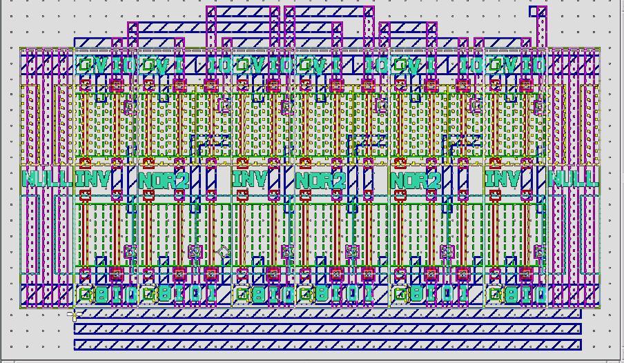
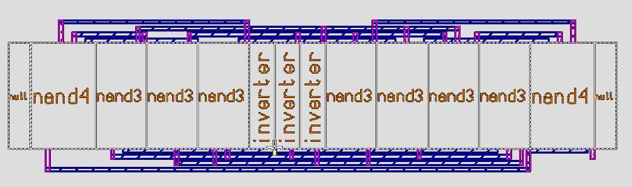
22 LAYOUT FOR XOR Page 22


23 BASIC DIGITAL CELLS WITH PADS Decoder Multiplexer XOR Full Adder Encoder Decoder Demux Edge Triggered D FF JK FF Page 23

24 4 TO 1 MULTIPLEXER I 0 A I 1 I 2 Q B I 3 Page 24

25 4 TO 1 MUX - GATE LEVEL SIMULATION Page 25
26 ADDITION IN BINARY IN BASE IN BINARY 11 CARRY SUM A TRUTH TABLE FOR ADDITION RULES B CIN SUM COUT Page 26
27 AND-OR CIRCUIT REALIZATION OF SUM TRUTH TABLE FOR ADDITION RULES A B CIN SUM COUT SUM A B Cin Page 27
28 CIRCUIT REALIZATION OF CARRY OUT (COUT) TRUTH TABLE FOR ADDITION RULES A B CIN SUM COUT COUT A B Cin Page 28

29 FULL ADDER Page 29

30 1 TO 4 DEMULTIPLEXER I A B Q 0 Q 1 Q 2 Q 3 Page 30

31 DECODER A Q 0 Q 1 B Q 2 Q 3 Page 31

32 ENCODER Q 0 Q 1 Q 2 Q n Digital Encoder Coded Output Lines 512 inputs can be coded into 9 lines which is a more dramatic benefit A B C D Q0 Q A B Q 1 C D No Connection Q 2 Page 32
33 FILP-FLOPS RS FLIP FLOP R S Q QBAR R S Q 0 0 Qn INDETERMINATE D FLIP FLOP Q DATA CLOCK QBAR Q=DATA IF CLOCK IS HIGH IF CLOCK IS LOW Q=PREVIOUS DATA VALUE Page 33
34 MASTER-SLAVE D FLIP FLOP DATA CLOCK Q QBAR A B NEGATED INPUT NOR IS EQUAL TO AND A A OUT = B B A B A B OUT OUT Page 34
35 ALL NOR MASTER SLAVE D FLIP FLOP Q DATA CLOCK DATA Q CLOCK ALL NOR NMOS REALIZATION ALLOWS FOR LOWER SUPPLY VOLTAGE Page 35
36 CMOS CLOCKED DATA LATCH USING AND-OR-INV D CLK _ Q Q V DD Q CLK D _ Q V DD CLK _ D Page 36

37 EDGE TRIGGERED D TYPE FLIP FLOP Page 37

38 JK FLIP FLOP Page 38

39 T-TYPE FILP-FLOP TOGGEL FLIP FLOP T Q QBAR Q: Toggles High and Low with Each Input T Qn-1 Q Page 39
40 BINARY COUNTER USING T TYPE FLIP FLOPS Input Pulses T A T B Tc A A B B C C T A State Table for Binary Counter Present Next F-F State State Inputs A B C T A T B T C B Qn-1 C Q TOGGEL FLIP FLOP A BC T A 0 A BC T B A BC T C Page 40

41 3-BIT BINARY COUNTER WITH D FLIP FLOPS Page 41
42 INVERTER WITH HYSTERESIS R=100K V1 5V 3 M2 Vout M3 Inverter with Hysteresis Vout 2 7 V2=0-5 Or M1 Vin The voltage on node 7 is different depending on if Vout is high or low. Changing Microelectronic the Voltage Engineering from source to substrate which changes the threshold voltage of M2 Page 42
43 INVERTER WITH HYSTERESIS SPICE shows inverter has hysteresis (Flip Blue output about the y-axis and superimpose on Red-Green Plot) Page 43

44 RC OSCILLATOR USING INVERTER WITH HYSTERESIS R C Vout RC Oscillator Page 44
45 BUFFERS R C RC Oscillator Vout Buffers Vout Page 45
46 CMOS INVERTER WITH HYSTERESIS SPICE show this inverter has hysteresis Page 46
47 OSCILLATOR CMOS INVERTER WITH HYSTERESIS R Vout C RC Oscillator Page 47
48 REFERNCES 1. Hodges Jackson and Saleh, Analysis and Design of Digital Integrated Circuits, Chapter Sedra and Smith, Microelectronic Circuits, Sixth Edition, Chapter Dr. Fuller s Lecture Notes, Page 48
49 HOMEWORK LOGIC 1. Design a pseudo NMOS NAND gate. Use 1um technology. Show it will work using SPICE. 2. Look up the data sheet for the MM74C14 CMOS inverter with hystersis. Design a 10 Khz oscillator. 3. Use SPICE (transistor level) to simulate the 1 to 4 Demultiplexer. 4. Use SPICE (transistor level) to simulate the positive edge triggered D-type Flip-Flop. 5. Use SPICE to simulate a CMOS RC Oscillator with Buffers. Page 49
50 SPICE MODELS FOR MOSFETS *SPICE MODELS FOR RIT DEVICES - DR. LYNN FULLER *LOCATION DR.FULLER'S WEBPAGE - * *Used in Electronics II for CD4007 inverter chip *Note: Properties L=1u W=200u.MODEL RIT4007N7 NMOS (LEVEL=7 +VERSION=3.1 CAPMOD=2 MOBMOD=1 +TOX=1.5E-8 XJ=1.84E-7 NCH=1.45E17 NSUB=5.33E16 XT=8.66E-8 +VTH0=1.0 U0= 600 WINT=2.0E-7 LINT=1E-7 +NGATE=5E20 RSH=1082 JS=3.23E-8 JSW=3.23E-8 CJ=6.8E-4 MJ=0.5 PB=0.95 +CJSW=1.26E-10 MJSW=0.5 PBSW=0.95 PCLM=5 +CGSO=3.4E-10 CGDO=3.4E-10 CGBO=5.75E-10) * *Used in Electronics II for CD4007 inverter chip *Note: Properties L=1u W=200u.MODEL RIT4007P7 PMOS (LEVEL=7 +VERSION=3.1 CAPMOD=2 MOBMOD=1 +TOX=1.5E-8 XJ=2.26E-7 NCH=7.12E16 NSUB=3.16E16 XT=8.66E-8 +VTH0=-1.0 U0= WINT=2.0E-7 LINT=2.26E-7 +NGATE=5E20 RSH=1347 JS=3.51E-8 JSW=3.51E-8 CJ=5.28E-4 MJ=0.5 PB=0.94 +CJSW=1.19E-10 MJSW=0.5 PBSW=0.94 +CGSO=4.5E-10 CGDO=4.5E-10 CGBO=5.75E-10) Page 50
51 SPICE MODELS FOR MOSFETS *Used for ALD1103 chips *Note: Properties L=10u W=880u.MODEL RITALDN3 NMOS (LEVEL=3 +TPG=1 TOX=6.00E-8 LD=2.08E-6 WD=4.00E-7 +U0= 1215 VTO=0.73 THETA=0.222 RS=0.74 RD=0.74 DELTA=2.5 +NSUB=1.57E16 XJ=1.3E-6 VMAX=4.38E6 ETA=0.913 KAPPA=0.074 NFS=3E11 +CGSO=5.99E-10 CGDO=5.99E-10 CGBO=4.31E-10 PB=0.90 XQC=0.4) * *Used for ALD1103 chips *Note: Properties L=10u W=880u.MODEL RITALDP3 PMOS (LEVEL=3 +TPG=1 TOX=6.00E-8 LD=2.08E-6 WD=4.00E-7 +U0=550 VTO=-0.73 THETA=0.222 RS=0.74 RD=0.74 DELTA=2.5 +NSUB=1.57E16 XJ=1.3E-6 VMAX=4.38E6 ETA=0.913 KAPPA=0.074 NFS=3E11 +CGSO=5.99E-10 CGDO=5.99E-10 CGBO=4.31E-10 PB=0.90 XQC=0.4) Page 51
52 SPICE MODELS FOR MOSFETS * LTSPICE uses Level=8 *For RIT Sub-CMOS 150 process with L=2u.MODEL RITSUBN8 NMOS (LEVEL=8 +VERSION=3.1 CAPMOD=2 MOBMOD=1 +TOX=1.5E-8 XJ=1.84E-7 NCH=1.45E17 NSUB=5.33E16 XT=8.66E-8 +VTH0=1.0 U0= 600 WINT=2.0E-7 LINT=1E-7 +NGATE=5E20 RSH=1082 JS=3.23E-8 JSW=3.23E-8 CJ=6.8E-4 MJ=0.5 PB=0.95 +CJSW=1.26E-10 MJSW=0.5 PBSW=0.95 PCLM=5 +CGSO=3.4E-10 CGDO=3.4E-10 CGBO=5.75E-10) * * LTSPICE uses Level=8 *For RIT Sub-CMOS 150 process with L=2u.MODEL RITSUBP8 PMOS (LEVEL=8 +VERSION=3.1 CAPMOD=2 MOBMOD=1 +TOX=1.5E-8 XJ=2.26E-7 NCH=7.12E16 NSUB=3.16E16 XT=8.66E-8 +VTH0=-1.0 U0= WINT=2.0E-7 LINT=2.26E-7 +NGATE=5E20 RSH=1347 JS=3.51E-8 JSW=3.51E-8 CJ=5.28E-4 MJ=0.5 PB=0.94 +CJSW=1.19E-10 MJSW=0.5 PBSW=0.94 +CGSO=4.5E-10 CGDO=4.5E-10 CGBO=5.75E-10) Page 52
53 SPICE MODELS FOR MOSFETS * From Sub-Micron CMOS Manufacturing Classes in MicroE ~ 1um Technology.MODEL RITSUBN7 NMOS (LEVEL=7 +VERSION=3.1 CAPMOD=2 MOBMOD=1 +TOX=1.5E-8 XJ=1.84E-7 NCH=1.45E17 NSUB=5.33E16 XT=8.66E-8 +VTH0=1.0 U0= 600 WINT=2.0E-7 LINT=1E-7 +NGATE=5E20 RSH=1082 JS=3.23E-8 JSW=3.23E-8 CJ=6.8E-4 MJ=0.5 PB=0.95 +CJSW=1.26E-10 MJSW=0.5 PBSW=0.95 PCLM=5 +CGSO=3.4E-10 CGDO=3.4E-10 CGBO=5.75E-10) * *From Sub-Micron CMOS Manufacturing Classes in MicroE ~ 1um Technology.MODEL RITSUBP7 PMOS (LEVEL=7 +VERSION=3.1 CAPMOD=2 MOBMOD=1 +TOX=1.5E-8 XJ=2.26E-7 NCH=7.12E16 NSUB=3.16E16 XT=8.66E-8 +VTH0=-1.0 U0= WINT=2.0E-7 LINT=2.26E-7 +NGATE=5E20 RSH=1347 JS=3.51E-8 JSW=3.51E-8 CJ=5.28E-4 MJ=0.5 PB=0.94 +CJSW=1.19E-10 MJSW=0.5 PBSW=0.94 +CGSO=4.5E-10 CGDO=4.5E-10 CGBO=5.75E-10) Page 53
54 SPICE MODELS FOR MOSFETS * LTSPICE uses Level=8 * From Electronics II EEEE482 FOR ~100nm Technology.model EECMOSN NMOS (LEVEL=8 +VERSION=3.1 CAPMOD=2 MOBMOD=1 +TOX=5E-9 XJ=1.84E-7 NCH=1E17 NSUB=5E16 XT=5E-8 +VTH0=0.4 U0= 200 WINT=1E-8 LINT=1E-8 +NGATE=5E20 RSH=1000 JS=3.23E-8 JSW=3.23E-8 CJ=6.8E-4 MJ=0.5 PB=0.95 +CJSW=1.26E-10 MJSW=0.5 PBSW=0.95 PCLM=5 +CGSO=3.4E-10 CGDO=3.4E-10 CGBO=5.75E-10) * * LTSPICE uses Level=8 * From Electronics II EEEE482 FOR ~100nm Technology.model EECMOSP PMOS (LEVEL=8 +TOX=5E-9 XJ=0.05E-6 NCH=1E17 NSUB=5E16 XT=5E-8 +VTH0=-0.4 U0= 100 WINT=1E-8 LINT=1E-8 +NGATE=5E20 RSH=1000 JS=3.51E-8 JSW=3.51E-8 CJ=5.28E-4 MJ=0.5 PB=0.94 +CJSW=1.19E-10 MJSW=0.5 PBSW=0.94 PCLM=5 +CGSO=4.5E-10 CGDO=4.5E-10 CGBO=5.75E-10) * Page 54
Transfer Gate and Dynamic Logic Dr. Lynn Fuller Webpage:
 ROCHESTER INSTITUTE OF TECHNOLOGY MICROELECTRONIC ENGINEERING Transfer Gate and Dynamic Logic Dr. Lynn Fuller Webpage: http://people.rit.edu/lffeee 82 Lomb Memorial Drive Rochester, NY 14623-5604 Tel (585)
MOS Amplifiers Dr. Lynn Fuller Webpage:
 ROCHESTER INSTITUTE OF TECHNOLOGY MICROELECTRONIC ENGINEERING Dr. Lynn Fuller Webpage: http://people.rit.edu/lffeee 82 Lomb Memorial Drive Rochester, NY 14623-5604 Email: Lynn.Fuller@rit.edu Department
High Speed Logic Circuits Dr. Lynn Fuller Webpage:
 ROCHESTER INSTITUTE OF TECHNOLOGY MICROELECTRONIC ENGINEERING Circuits Webpage: http://people.rit.edu/lffeee 82 Lomb Memorial Drive Rochester, NY 14623-5604 Tel (585) 475-2035 Fax (585) 475-5041 Email:
MOSFET Internal Capacitance Dr. Lynn Fuller Webpage:
 ROCHESTER INSTITUTE OF TECHNOLOGY MICROELECTRONIC ENGINEERING Dr. Lynn Fuller Webpage: http://people.rit.edu/lffeee 82 Lomb Memorial Drive Rochester, NY 14623-5604 Email: Lynn.Fuller@rit.edu Department
Introduction to VLSI Dr. Lynn Fuller
 ROCHESTER INSTITUTE OF TECHNOLOGY MICROELECTRONIC ENGINEERING Introduction to VLSI Dr. Lynn Fuller Webpage: http://people.rit.edu/lffeee 82 Lomb Memorial Drive Rochester, NY 14623-5604 Tel (585) 475-2035
Low Power CMOS Dr. Lynn Fuller Webpage:
 ROCHESTER INSTITUTE OF TECHNOLOGY MICROELECTRONIC ENGINEERING Dr. Lynn Fuller Webpage: http://people.rit.edu/lffeee 82 Lomb Memorial Drive Rochester, NY 14623-5604 Email: Lynn.Fuller@rit.edu Department
EE141Microelettronica. CMOS Logic
 Microelettronica CMOS Logic CMOS logic Power consumption in CMOS logic gates Where Does Power Go in CMOS? Dynamic Power Consumption Charging and Discharging Capacitors Short Circuit Currents Short Circuit
Sequential Logic. Rab Nawaz Khan Jadoon DCS. Lecturer COMSATS Lahore Pakistan. Department of Computer Science
 Sequential Logic Rab Nawaz Khan Jadoon DCS COMSATS Institute of Information Technology Lecturer COMSATS Lahore Pakistan Digital Logic and Computer Design Sequential Logic Combinational circuits with memory
Digital Integrated Circuits A Design Perspective
 Digital Integrated Circuits A Design Perspective Jan M. Rabaey Anantha Chandrakasan Borivoje Nikolic Designing Sequential Logic Circuits November 2002 Sequential Logic Inputs Current State COMBINATIONAL
Topics. Dynamic CMOS Sequential Design Memory and Control. John A. Chandy Dept. of Electrical and Computer Engineering University of Connecticut
 Topics Dynamic CMOS Sequential Design Memory and Control Dynamic CMOS In static circuits at every point in time (except when switching) the output is connected to either GND or V DD via a low resistance
ECE 546 Lecture 10 MOS Transistors
 ECE 546 Lecture 10 MOS Transistors Spring 2018 Jose E. Schutt-Aine Electrical & Computer Engineering University of Illinois jesa@illinois.edu NMOS Transistor NMOS Transistor N-Channel MOSFET Built on p-type
LOGIC CIRCUITS. Basic Experiment and Design of Electronics. Ho Kyung Kim, Ph.D.
 Basic Experiment and Design of Electronics LOGIC CIRCUITS Ho Kyung Kim, Ph.D. hokyung@pusan.ac.kr School of Mechanical Engineering Pusan National University Digital IC packages TTL (transistor-transistor
Circuit A. Circuit B
 UNIVERSITY OF CALIFORNIA College of Engineering Department of Electrical Engineering and Computer Sciences Last modified on November 19, 2006 by Karl Skucha (kskucha@eecs) Borivoje Nikolić Homework #9
LOGIC CIRCUITS. Basic Experiment and Design of Electronics
 Basic Experiment and Design of Electronics LOGIC CIRCUITS Ho Kyung Kim, Ph.D. hokyung@pusan.ac.kr School of Mechanical Engineering Pusan National University Outline Combinational logic circuits Output
GMU, ECE 680 Physical VLSI Design
 ECE680: Physical VLSI esign Chapter IV esigning Sequential Logic Circuits (Chapter 7) 1 Sequential Logic Inputs Current State COMBINATIONAL LOGIC Registers Outputs Next state 2 storage mechanisms positive
Lecture 4: Implementing Logic in CMOS
 Lecture 4: Implementing Logic in CMOS Mark Mcermott Electrical and Computer Engineering The University of Texas at ustin Review of emorgan s Theorem Recall that: () = + and = ( + ) (+) = and + = ( ) ()
Gates and Flip-Flops
 Gates and Flip-Flops Chris Kervick (11355511) With Evan Sheridan and Tom Power December 2012 On a scale of 1 to 10, how likely is it that this question is using binary?...4? What s a 4? Abstract The operation
S No. Questions Bloom s Taxonomy Level UNIT-I
 GROUP-A (SHORT ANSWER QUESTIONS) S No. Questions Bloom s UNIT-I 1 Define oxidation & Classify different types of oxidation Remember 1 2 Explain about Ion implantation Understand 1 3 Describe lithography
Lecture Outline. ESE 570: Digital Integrated Circuits and VLSI Fundamentals. Review: 1st Order RC Delay Models. Review: Two-Input NOR Gate (NOR2)
") ESE 570: Digital Integrated Circuits and VLSI Fundamentals Lec 14: March 1, 2016 Combination Logic: Ratioed and Pass Logic Lecture Outline! CMOS Gates Review " CMOS Worst Case Analysis! Ratioed Logic Gates!
ESE 570: Digital Integrated Circuits and VLSI Fundamentals Lec 14: March 1, 2016 Combination Logic: Ratioed and Pass Logic Lecture Outline! CMOS Gates Review " CMOS Worst Case Analysis! Ratioed Logic Gates!
9/18/2008 GMU, ECE 680 Physical VLSI Design
 ECE680: Physical VLSI esign Chapter IV esigning Sequential Logic Circuits (Chapter 7) 1 Sequential Logic Inputs Current State COMBINATIONAL LOGIC Registers Outputs Next state 2 storage mechanisms positive
Digital Integrated Circuits A Design Perspective
 igital Integrated Circuits A esign Perspective Jan M. Rabaey Anantha Chandrakasan Borivoje Nikolic esigning Sequential Logic Circuits November 2002 Sequential Logic Inputs Current State COMBINATIONAL LOGIC
CMPEN 411. Spring Lecture 18: Static Sequential Circuits
 CMPEN 411 VLSI Digital Circuits Spring 2011 Lecture 18: Static Sequential Circuits [Adapted from Rabaey s Digital Integrated Circuits, Second Edition, 2003 J. Rabaey, A. Chandrakasan, B. Nikolic] Sp11
ESE 570: Digital Integrated Circuits and VLSI Fundamentals
 ESE 570: Digital Integrated Circuits and VLSI Fundamentals Lec 17: March 23, 2017 Energy and Power Optimization, Design Space Exploration, Synchronous MOS Logic Lecture Outline! Energy and Power Optimization
Topic 4. The CMOS Inverter
 Topic 4 The CMOS Inverter Peter Cheung Department of Electrical & Electronic Engineering Imperial College London URL: www.ee.ic.ac.uk/pcheung/ E-mail: p.cheung@ic.ac.uk Topic 4-1 Noise in Digital Integrated
Floating Point Representation and Digital Logic. Lecture 11 CS301
 Floating Point Representation and Digital Logic Lecture 11 CS301 Administrative Daily Review of today s lecture w Due tomorrow (10/4) at 8am Lab #3 due Friday (9/7) 1:29pm HW #5 assigned w Due Monday 10/8
ESE 570: Digital Integrated Circuits and VLSI Fundamentals
 ESE 570: Digital Integrated Circuits and VLSI Fundamentals Lec 18: March 27, 2018 Dynamic Logic, Charge Injection Lecture Outline! Sequential MOS Logic " D-Latch " Timing Constraints! Dynamic Logic " Domino
Digital Integrated Circuits A Design Perspective
 igital Integrated Circuits A esign Perspective Jan M. Rabaey Anantha Chandrakasan Borivoje Nikolic esigning Sequential Logic Circuits November 2002 Naming Conventions In our text: a latch is level sensitive
Jan M. Rabaey Anantha Chandrakasan Borivoje Nikolic. November Digital Integrated Circuits 2nd Sequential Circuits
 igital Integrated Circuits A esign Perspective Jan M. Rabaey Anantha Chandrakasan Borivoje Nikolic esigning i Sequential Logic Circuits November 2002 Sequential Logic Inputs Current State COMBINATIONAL
XI STANDARD [ COMPUTER SCIENCE ] 5 MARKS STUDY MATERIAL.
![XI STANDARD [ COMPUTER SCIENCE ] 5 MARKS STUDY MATERIAL.](/thumbs/81/84726747.jpg "XI STANDARD [ COMPUTER SCIENCE ] 5 MARKS STUDY MATERIAL.") 2017-18 XI STANDARD [ COMPUTER SCIENCE ] 5 MARKS STUDY MATERIAL HALF ADDER 1. The circuit that performs addition within the Arithmetic and Logic Unit of the CPU are called adders. 2. A unit that adds two
2017-18 XI STANDARD [ COMPUTER SCIENCE ] 5 MARKS STUDY MATERIAL HALF ADDER 1. The circuit that performs addition within the Arithmetic and Logic Unit of the CPU are called adders. 2. A unit that adds two
Chapter 5 CMOS Logic Gate Design
 Chapter 5 CMOS Logic Gate Design Section 5. -To achieve correct operation of integrated logic gates, we need to satisfy 1. Functional specification. Temporal (timing) constraint. (1) In CMOS, incorrect
S.Y. Diploma : Sem. III [CO/CM/IF/CD/CW] Digital Techniques
![S.Y. Diploma : Sem. III [CO/CM/IF/CD/CW] Digital Techniques](/thumbs/90/103932933.jpg "S.Y. Diploma : Sem. III [CO/CM/IF/CD/CW] Digital Techniques") S.Y. Diploma : Sem. III [CO/CM/IF/CD/CW] Digital Techniques Time: 3 Hrs.] Prelim Question Paper Solution [Marks : 100 Q.1(a) Attempt any SIX of the following : [12] Q.1(a) (i) Derive AND gate and OR gate
S.Y. Diploma : Sem. III [CO/CM/IF/CD/CW] Digital Techniques Time: 3 Hrs.] Prelim Question Paper Solution [Marks : 100 Q.1(a) Attempt any SIX of the following : [12] Q.1(a) (i) Derive AND gate and OR gate
Digital Integrated Circuits Designing Combinational Logic Circuits. Fuyuzhuo
 Digital Integrated Circuits Designing Combinational Logic Circuits Fuyuzhuo Introduction Digital IC Dynamic Logic Introduction Digital IC EE141 2 Dynamic logic outline Dynamic logic principle Dynamic logic
CMPEN 411 VLSI Digital Circuits. Lecture 04: CMOS Inverter (static view)
") CMPEN 411 VLSI Digital Circuits Lecture 04: CMOS Inverter (static view) Kyusun Choi [Adapted from Rabaey s Digital Integrated Circuits, Second Edition, 2003 J. Rabaey, A. Chandrakasan, B. Nikolic] CMPEN
CMPEN 411 VLSI Digital Circuits Lecture 04: CMOS Inverter (static view) Kyusun Choi [Adapted from Rabaey s Digital Integrated Circuits, Second Edition, 2003 J. Rabaey, A. Chandrakasan, B. Nikolic] CMPEN
KINGS COLLEGE OF ENGINEERING DEPARTMENT OF ELECTRONICS AND COMMUNICATION ENGINEERING QUESTION BANK
 KINGS COLLEGE OF ENGINEERING DEPARTMENT OF ELECTRONICS AND COMMUNICATION ENGINEERING QUESTION BANK SUBJECT CODE: EC 1354 SUB.NAME : VLSI DESIGN YEAR / SEMESTER: III / VI UNIT I MOS TRANSISTOR THEORY AND
Topics. CMOS Design Multi-input delay analysis. John A. Chandy Dept. of Electrical and Computer Engineering University of Connecticut
 Topics CMO Design Multi-input delay analysis pring 25 Transmission Gate OUT Z OUT Z pring 25 Transmission Gate OUT When is low, the output is at high impedance When is high, the output follows However,
Hold Time Illustrations
 Hold Time Illustrations EE213-L09-Sequential Logic.1 Pingqiang, ShanghaiTech, 2018 Hold Time Illustrations EE213-L09-Sequential Logic.2 Pingqiang, ShanghaiTech, 2018 Hold Time Illustrations EE213-L09-Sequential
ECE 342 Electronic Circuits. Lecture 34 CMOS Logic
 ECE 34 Electronic Circuits Lecture 34 CMOS Logic Jose E. Schutt-Aine Electrical & Computer Engineering University of Illinois jesa@illinois.edu 1 De Morgan s Law Digital Logic - Generalization ABC... ABC...
Sample Test Paper - I
 Scheme G Sample Test Paper - I Course Name : Computer Engineering Group Marks : 25 Hours: 1 Hrs. Q.1) Attempt any THREE: 09 Marks a) Define i) Propagation delay ii) Fan-in iii) Fan-out b) Convert the following:
Integrated Circuits & Systems
 Federal University of Santa Catarina Center for Technology Computer Science & Electronics Engineering Integrated Circuits & Systems INE 5442 Lecture 16 CMOS Combinational Circuits - 2 guntzel@inf.ufsc.br
MOSIS REPORT. Spring MOSIS Report 1. MOSIS Report 2. MOSIS Report 3
 MOSIS REPORT Spring 2010 MOSIS Report 1 MOSIS Report 2 MOSIS Report 3 MOSIS Report 1 Design of 4-bit counter using J-K flip flop I. Objective The purpose of this project is to design one 4-bit counter
Lecture 5: DC & Transient Response
 Lecture 5: DC & Transient Response Outline q Pass Transistors q DC Response q Logic Levels and Noise Margins q Transient Response q RC Delay Models q Delay Estimation 2 Activity 1) If the width of a transistor
Appendix A: Digital Logic. Principles of Computer Architecture. Principles of Computer Architecture by M. Murdocca and V. Heuring
 - Principles of Computer rchitecture Miles Murdocca and Vincent Heuring 999 M. Murdocca and V. Heuring -2 Chapter Contents. Introduction.2 Combinational Logic.3 Truth Tables.4 Logic Gates.5 Properties
Lecture Outline. ESE 570: Digital Integrated Circuits and VLSI Fundamentals. Total Power. Energy and Power Optimization. Worksheet Problem 1
 ESE 570: Digital Integrated Circuits and VLSI Fundamentals Lec 16: March 20, 2018 Energy and Power Optimization, Design Space Exploration Lecture Outline! Energy and Power Optimization " Tradeoffs! Design
S.Y. Diploma : Sem. III [DE/ED/EI/EJ/EN/ET/EV/EX/IC/IE/IS/IU/MU] Principles of Digital Techniques
![S.Y. Diploma : Sem. III [DE/ED/EI/EJ/EN/ET/EV/EX/IC/IE/IS/IU/MU] Principles of Digital Techniques](/thumbs/82/86792063.jpg "S.Y. Diploma : Sem. III [DE/ED/EI/EJ/EN/ET/EV/EX/IC/IE/IS/IU/MU] Principles of Digital Techniques") S.Y. Diploma : Sem. III [DE/ED/EI/EJ/EN/ET/EV/EX/IC/IE/IS/IU/MU] Principles of Digital Techniques Time: 3 Hrs.] Prelim Question Paper Solution [Marks : 100 Q.1(a) Attempt any SIX of the following : [12]
S.Y. Diploma : Sem. III [DE/ED/EI/EJ/EN/ET/EV/EX/IC/IE/IS/IU/MU] Principles of Digital Techniques Time: 3 Hrs.] Prelim Question Paper Solution [Marks : 100 Q.1(a) Attempt any SIX of the following : [12]
CMOS Inverter (static view)
") Review: Design Abstraction Levels SYSTEM CMOS Inverter (static view) + MODULE GATE [Adapted from Chapter 5. 5.3 CIRCUIT of G DEVICE Rabaey s Digital Integrated Circuits,, J. Rabaey et al.] S D Review:
Review: Design Abstraction Levels SYSTEM CMOS Inverter (static view) + MODULE GATE [Adapted from Chapter 5. 5.3 CIRCUIT of G DEVICE Rabaey s Digital Integrated Circuits,, J. Rabaey et al.] S D Review:
MAHALAKSHMI ENGINEERING COLLEGE TIRUCHIRAPALLI
 DEPARTMENT: ECE MAHALAKSHMI ENGINEERING COLLEGE TIRUCHIRAPALLI 6 QUESTION BANK SUBJECT NAME: DIGITAL ELECTRONICS UNIT : Design of Sequential Circuits PART A ( Marks). Draw the logic diagram 4: Multiplexer.(AUC
PRESIDENCY UNIVERSITY DEPARTMENT OF ELECTRICAL AND COMPUTER ENGINEERING EE 310: VLSI System Laboratory. Contents
 PRESIDENCY UNIVERSITY DEPARTMENT OF ELECTRICAL AND COMPUTER ENGINEERING EE 310: VLSI System Laboratory Contents Experiment No Name of The Experiments. Page Experiment-1 INTRODUCTION TO CIRCUIT SIMULATION
Lecture 4: DC & Transient Response
 Introduction to CMOS VLSI Design Lecture 4: DC & Transient Response David Harris Harvey Mudd College Spring 004 Outline DC Response Logic Levels and Noise Margins Transient Response Delay Estimation Slide
 vidyarthiplus.com vidyarthiplus.com vidyarthiplus.com ANNA UNIVERSITY- COMBATORE B.E./ B.TECH. DEGREE EXAMINATION - JUNE 2009. ELECTRICAL & ELECTONICS ENGG. - FOURTH SEMESTER DIGITAL LOGIC CIRCUITS PART-A
Lab 3 Revisited. Zener diodes IAP 2008 Lecture 4 1
 Lab 3 Revisited Zener diodes R C 6.091 IAP 2008 Lecture 4 1 Lab 3 Revisited +15 Voltage regulators 555 timers 270 1N758 0.1uf 5K pot V+ V- 2N2222 0.1uf V o. V CC V Vin s = 5 V Vc V c Vs 1 e t = RC Threshold
MOSFET and CMOS Gate. Copy Right by Wentai Liu
 MOSFET and CMOS Gate CMOS Inverter DC Analysis - Voltage Transfer Curve (VTC) Find (1) (2) (3) (4) (5) (6) V OH min, V V OL min, V V IH min, V V IL min, V OHmax OLmax IHmax ILmax NM L = V ILmax V OL max
MAHARASHTRA STATE BOARD OF TECHNICAL EDUCATION (Autonomous) (ISO/IEC Certified)
 (ISO/IEC Certified)") WINTER 17 EXAMINATION Subject Name: Digital Techniques Model Answer Subject Code: 17333 Important Instructions to examiners: 1) The answers should be examined by key words and not as word-to-word as given
WINTER 17 EXAMINATION Subject Name: Digital Techniques Model Answer Subject Code: 17333 Important Instructions to examiners: 1) The answers should be examined by key words and not as word-to-word as given
on candidate s understanding. 7) For programming language papers, credit may be given to any other program based on equivalent concept.
 For programming language papers, credit may be given to any other program based on equivalent concept.") WINTER 17 EXAMINATION Subject Name: Digital Techniques Model Answer Subject Code: 17333 Important Instructions to examiners: 1) The answers should be examined by key words and not as word-to-word as given
WINTER 17 EXAMINATION Subject Name: Digital Techniques Model Answer Subject Code: 17333 Important Instructions to examiners: 1) The answers should be examined by key words and not as word-to-word as given
EECS 312: Digital Integrated Circuits Midterm Exam 2 December 2010
 Signature: EECS 312: Digital Integrated Circuits Midterm Exam 2 December 2010 obert Dick Show your work. Derivations are required for credit; end results are insufficient. Closed book. No electronic mental
Philadelphia University Student Name: Student Number:
 Philadelphia University Student Name: Student Number: Faculty of Engineering Serial Number: Final Exam, Second Semester: 2015/2016 Dept. of Computer Engineering Course Title: Logic Circuits Date: 08/06/2016
Digital Circuits. 1. Inputs & Outputs are quantized at two levels. 2. Binary arithmetic, only digits are 0 & 1. Position indicates power of 2.
 Digital Circuits 1. Inputs & Outputs are quantized at two levels. 2. inary arithmetic, only digits are 0 & 1. Position indicates power of 2. 11001 = 2 4 + 2 3 + 0 + 0 +2 0 16 + 8 + 0 + 0 + 1 = 25 Digital
Digital Integrated Circuits A Design Perspective
 Digital Integrated Circuits Design Perspective Designing Combinational Logic Circuits Fuyuzhuo School of Microelectronics,SJTU Introduction Digital IC Dynamic Logic Introduction Digital IC 2 EE141 Dynamic
Study of MOSFET circuit
 ECE 570 Computer Aided Engineering for Integrated Circuits IC 752 - E Simulation Assignment No. 3 - Due: Oct. 30 (Th.), 2003 Study of MOSFET circuit Simulate the basic circuit of CMOS shift register shown
Integrated Circuits & Systems
 Federal University of Santa Catarina Center for Technology Computer Science & Electronics Engineering Integrated Circuits & Systems INE 5442 Lecture 18 CMOS Sequential Circuits - 1 guntzel@inf.ufsc.br
EEC 118 Lecture #6: CMOS Logic. Rajeevan Amirtharajah University of California, Davis Jeff Parkhurst Intel Corporation
 EEC 118 Lecture #6: CMOS Logic Rajeevan mirtharajah University of California, Davis Jeff Parkhurst Intel Corporation nnouncements Quiz 1 today! Lab 2 reports due this week Lab 3 this week HW 3 due this
EE141- Spring 2007 Digital Integrated Circuits
 EE141- Spring 27 igital Integrated Circuits Lecture 19 Sequential Circuits 1 Administrative Stuff Project Ph. 2 due Tu. 5pm 24 Cory box + email ee141- project@bwrc.eecs.berkeley.edu Hw 8 Posts this Fr.,
DIGITAL LOGIC CIRCUITS
 DIGITAL LOGIC CIRCUITS Introduction Logic Gates Boolean Algebra Map Specification Combinational Circuits Flip-Flops Sequential Circuits Memory Components Integrated Circuits Digital Computers 2 LOGIC GATES
Lecture 7: Logic design. Combinational logic circuits
 /24/28 Lecture 7: Logic design Binary digital circuits: Two voltage levels: and (ground and supply voltage) Built from transistors used as on/off switches Analog circuits not very suitable for generic
Sequential Logic Circuits
 Chapter 4 Sequential Logic Circuits 4 1 The defining characteristic of a combinational circuit is that its output depends only on the current inputs applied to the circuit. The output of a sequential circuit,
UNIVERSITY OF CALIFORNIA, BERKELEY College of Engineering Department of Electrical Engineering and Computer Sciences
 UNIVERSITY OF CALIFORNIA, BERKELEY College of Engineering Department of Electrical Engineering and Computer Sciences Elad Alon Homework #2 EECS141 Due Thursday, September 9, 5pm, box in 240 Cory PROBLEM
ECE 342 Solid State Devices & Circuits 4. CMOS
 ECE 34 Solid State Devices & Circuits 4. CMOS Jose E. Schutt-Aine Electrical & Computer Engineering University of Illinois jschutt@emlab.uiuc.edu ECE 34 Jose Schutt Aine 1 Digital Circuits V IH : Input
Lecture 6: DC & Transient Response
 Lecture 6: DC & Transient Response Slides courtesy of Deming Chen Slides based on the initial set from David Harris CMOS VLSI Design Outline Pass Transistors DC Response Logic Levels and Noise Margins
Fig. 1 CMOS Transistor Circuits (a) Inverter Out = NOT In, (b) NOR-gate C = NOT (A or B)
 Inverter Out = NOT In, (b) NOR-gate C = NOT (A or B)") 1 Introduction to Transistor-Level Logic Circuits 1 By Prawat Nagvajara At the transistor level of logic circuits, transistors operate as switches with the logic variables controlling the open or closed
1 Introduction to Transistor-Level Logic Circuits 1 By Prawat Nagvajara At the transistor level of logic circuits, transistors operate as switches with the logic variables controlling the open or closed
Fundamentals of Digital Design
 Fundamentals of Digital Design Digital Radiation Measurement and Spectroscopy NE/RHP 537 1 Binary Number System The binary numeral system, or base-2 number system, is a numeral system that represents numeric
L2: Combinational Logic Design (Construction and Boolean Algebra)
") L2: Combinational Logic Design (Construction and Boolean Algebra) Acknowledgements: Lecture material adapted from Chapter 2 of R. Katz, G. Borriello, Contemporary Logic Design (second edition), Pearson
L2: Combinational Logic Design (Construction and Boolean Algebra) Acknowledgements: Lecture material adapted from Chapter 2 of R. Katz, G. Borriello, Contemporary Logic Design (second edition), Pearson
ELCT201: DIGITAL LOGIC DESIGN
 ELCT201: DIGITAL LOGIC DESIGN Dr. Eng. Haitham Omran, haitham.omran@guc.edu.eg Dr. Eng. Wassim Alexan, wassim.joseph@guc.edu.eg Lecture 6 Following the slides of Dr. Ahmed H. Madian محرم 1439 ه Winter
UNIVERSITY OF BOLTON SCHOOL OF ENGINEERING BENG (HONS) ELECTRICAL & ELECTRONICS ENGINEERING EXAMINATION SEMESTER /2017
 ELECTRICAL & ELECTRONICS ENGINEERING EXAMINATION SEMESTER /2017") UNIVERSITY OF BOLTON TW35 SCHOOL OF ENGINEERING BENG (HONS) ELECTRICAL & ELECTRONICS ENGINEERING EXAMINATION SEMESTER 2-2016/2017 INTERMEDIATE DIGITAL ELECTRONICS AND COMMUNICATIONS MODULE NO: EEE5002
UNIVERSITY OF BOLTON TW35 SCHOOL OF ENGINEERING BENG (HONS) ELECTRICAL & ELECTRONICS ENGINEERING EXAMINATION SEMESTER 2-2016/2017 INTERMEDIATE DIGITAL ELECTRONICS AND COMMUNICATIONS MODULE NO: EEE5002
CMOS Logic Gates. University of Connecticut 172
 CMOS Logic Gates University of Connecticut 172 Basic CMOS Inverter Operation V IN P O N O p-channel enhancementtype MOSFET; V T < 0 n-channel enhancementtype MOSFET; V T > 0 If V IN 0, N O is cut off and
Simulation of Logic Primitives and Dynamic D-latch with Verilog-XL
 Simulation of Logic Primitives and Dynamic D-latch with Verilog-XL November 30, 2011 Robert D Angelo Tufts University Electrical and Computer Engineering EE-103 Lab 3: Part I&II Professor: Dr. Valencia
Number System. Decimal to binary Binary to Decimal Binary to octal Binary to hexadecimal Hexadecimal to binary Octal to binary
 Number System Decimal to binary Binary to Decimal Binary to octal Binary to hexadecimal Hexadecimal to binary Octal to binary BOOLEAN ALGEBRA BOOLEAN LOGIC OPERATIONS Logical AND Logical OR Logical COMPLEMENTATION
ENGR890 Digital VLSI Design Fall Lecture 4: CMOS Inverter (static view)
") ENGR89 Digital VLSI Design Fall 5 Lecture 4: CMOS Inverter (static view) [Adapted from Chapter 5 of Digital Integrated Circuits, 3, J. Rabaey et al.] [Also borrowed from Vijay Narayanan and Mary Jane Irwin]
ENGR89 Digital VLSI Design Fall 5 Lecture 4: CMOS Inverter (static view) [Adapted from Chapter 5 of Digital Integrated Circuits, 3, J. Rabaey et al.] [Also borrowed from Vijay Narayanan and Mary Jane Irwin]
Spiral 2 7. Capacitance, Delay and Sizing. Mark Redekopp
 2-7.1 Spiral 2 7 Capacitance, Delay and Sizing Mark Redekopp 2-7.2 Learning Outcomes I understand the sources of capacitance in CMOS circuits I understand how delay scales with resistance, capacitance
Power Dissipation. Where Does Power Go in CMOS?
 Power Dissipation [Adapted from Chapter 5 of Digital Integrated Circuits, 2003, J. Rabaey et al.] Where Does Power Go in CMOS? Dynamic Power Consumption Charging and Discharging Capacitors Short Circuit
Micro Spectro Photometer ROCHESTER INSTITUTE OF TECHNOLOGY MICROELECTRONIC ENGINEERING. Dr. Lynn Fuller. Webpage:
 ROCHESTER INSTITUTE OF TECHNOLOGY MICROELECTRONIC ENGINEERING Micro Spectro Photometer Dr. Lynn Fuller Webpage: http://people.rit.edu/lffeee 82 Lomb Memorial Drive Rochester, NY 146235604 Tel (585) 4752035
UNIT 8A Computer Circuitry: Layers of Abstraction. Boolean Logic & Truth Tables
 UNIT 8 Computer Circuitry: Layers of bstraction 1 oolean Logic & Truth Tables Computer circuitry works based on oolean logic: operations on true (1) and false (0) values. ( ND ) (Ruby: && ) 0 0 0 0 0 1
EE5780 Advanced VLSI CAD
 EE5780 Advanced VLSI CAD Lecture 4 DC and Transient Responses, Circuit Delays Zhuo Feng 4.1 Outline Pass Transistors DC Response Logic Levels and Noise Margins Transient Response RC Delay Models Delay
THE INVERTER. Inverter
 THE INVERTER DIGITAL GATES Fundamental Parameters Functionality Reliability, Robustness Area Performance» Speed (delay)» Power Consumption» Energy Noise in Digital Integrated Circuits v(t) V DD i(t) (a)
Vidyalankar S.E. Sem. III [CMPN] Digital Logic Design and Analysis Prelim Question Paper Solution
![Vidyalankar S.E. Sem. III [CMPN] Digital Logic Design and Analysis Prelim Question Paper Solution](/thumbs/90/103673562.jpg "Vidyalankar S.E. Sem. III [CMPN] Digital Logic Design and Analysis Prelim Question Paper Solution") . (a) (i) ( B C 5) H (A 2 B D) H S.E. Sem. III [CMPN] Digital Logic Design and Analysis Prelim Question Paper Solution ( B C 5) H (A 2 B D) H = (FFFF 698) H (ii) (2.3) 4 + (22.3) 4 2 2. 3 2. 3 2 3. 2 (2.3)
. (a) (i) ( B C 5) H (A 2 B D) H S.E. Sem. III [CMPN] Digital Logic Design and Analysis Prelim Question Paper Solution ( B C 5) H (A 2 B D) H = (FFFF 698) H (ii) (2.3) 4 + (22.3) 4 2 2. 3 2. 3 2 3. 2 (2.3)
Dynamic Combinational Circuits. Dynamic Logic
 Dynamic Combinational Circuits Dynamic circuits Charge sharing, charge redistribution Domino logic np-cmos (zipper CMOS) Krish Chakrabarty 1 Dynamic Logic Dynamic gates use a clocked pmos pullup Two modes:
ENGR4300 Fall 2005 Test 3A. Name. Section. Question 1 (25 points) Question 2 (25 points) Question 3 (25 points) Question 4 (25 points)
 Question 2 (25 points) Question 3 (25 points) Question 4 (25 points)") ENGR4 Test A Fall 5 ENGR4 Fall 5 Test A Name Section Question (5 points) Question (5 points) Question (5 points) Question 4 (5 points) Total ( points): Please do not write on the crib sheets. On all questions:
ENGR4 Test A Fall 5 ENGR4 Fall 5 Test A Name Section Question (5 points) Question (5 points) Question (5 points) Question 4 (5 points) Total ( points): Please do not write on the crib sheets. On all questions:
Chapter 13. Clocked Circuits SEQUENTIAL VS. COMBINATIONAL CMOS TG LATCHES, FLIP FLOPS. Baker Ch. 13 Clocked Circuits. Introduction to VLSI
 Chapter 13 Clocked Circuits SEQUENTIAL VS. COMBINATIONAL CMOS TG LATCHES, FLIP FLOPS SET-RESET (SR) ARBITER LATCHES FLIP FLOPS EDGE TRIGGERED DFF FF TIMING Joseph A. Elias, Ph.D. Adjunct Professor, University
EEC 116 Lecture #5: CMOS Logic. Rajeevan Amirtharajah Bevan Baas University of California, Davis Jeff Parkhurst Intel Corporation
 EEC 116 Lecture #5: CMOS Logic Rajeevan mirtharajah Bevan Baas University of California, Davis Jeff Parkhurst Intel Corporation nnouncements Quiz 1 today! Lab 2 reports due this week Lab 3 this week HW
Memory, Latches, & Registers
 Memory, Latches, & Registers 1) Structured Logic Arrays 2) Memory Arrays 3) Transparent Latches 4) How to save a few bucks at toll booths 5) Edge-triggered Registers L13 Memory 1 General Table Lookup Synthesis
KUMARAGURU COLLEGE OF TECHNOLOGY COIMBATORE
 Estd-1984 KUMARAGURU COLLEGE OF TECHNOLOGY COIMBATORE 641 006 QUESTION BANK UNIT I PART A ISO 9001:2000 Certified 1. Convert (100001110.010) 2 to a decimal number. 2. Find the canonical SOP for the function
University of Toronto Faculty of Applied Science and Engineering Edward S. Rogers Sr. Department of Electrical and Computer Engineering
 University of Toronto Faculty of Applied Science and Engineering Edward S. Rogers Sr. Department of Electrical and Computer Engineering Final Examination ECE 241F - Digital Systems Examiners: J. Rose and
CSE140: Components and Design Techniques for Digital Systems. Logic minimization algorithm summary. Instructor: Mohsen Imani UC San Diego
 CSE4: Components and Design Techniques for Digital Systems Logic minimization algorithm summary Instructor: Mohsen Imani UC San Diego Slides from: Prof.Tajana Simunic Rosing & Dr.Pietro Mercati Definition
Topics to be Covered. capacitance inductance transmission lines
 Topics to be Covered Circuit Elements Switching Characteristics Power Dissipation Conductor Sizes Charge Sharing Design Margins Yield resistance capacitance inductance transmission lines Resistance of
Lecture 9: Digital Electronics
 Introduction: We can classify the building blocks of a circuit or system as being either analog or digital in nature. If we focus on voltage as the circuit parameter of interest: nalog: The voltage can
Chapter 4. Sequential Logic Circuits
 Chapter 4 Sequential Logic Circuits 1 2 Chapter 4 4 1 The defining characteristic of a combinational circuit is that its output depends only on the current inputs applied to the circuit. The output of
EE 330 Homework 5 Spring 2017 (This assignment will not be collected or graded)
") EE 330 Homework 5 Spring 2017 (This assignment will not be collected or graded) Assume the CMOS process is characterized by model parameters V TH =1V and µc OX =100µA/V 2. If any other model parameters
EE 330 Homework 5 Spring 2017 (This assignment will not be collected or graded) Assume the CMOS process is characterized by model parameters V TH =1V and µc OX =100µA/V 2. If any other model parameters
CMPEN 411 VLSI Digital Circuits Spring Lecture 14: Designing for Low Power
 CMPEN 411 VLSI Digital Circuits Spring 2012 Lecture 14: Designing for Low Power [Adapted from Rabaey s Digital Integrated Circuits, Second Edition, 2003 J. Rabaey, A. Chandrakasan, B. Nikolic] Sp12 CMPEN
MODULE 5 Chapter 7. Clocked Storage Elements
 MODULE 5 Chapter 7 Clocked Storage Elements 3/9/2015 1 Outline Background Clocked Storage Elements Timing, terminology, classification Static CSEs Latches Registers Dynamic CSEs Latches Registers 3/9/2015
ECE 2300 Digital Logic & Computer Organization
 ECE 23 Digital Logic & Computer Organization Spring 28 Combinational Building Blocks Lecture 5: Announcements Lab 2 prelab due tomorrow HW due Friday HW 2 to be posted on Thursday Lecture 4 to be replayed
Static CMOS Circuits. Example 1
 Static CMOS Circuits Conventional (ratio-less) static CMOS Covered so far Ratio-ed logic (depletion load, pseudo nmos) Pass transistor logic ECE 261 Krish Chakrabarty 1 Example 1 module mux(input s, d0,
ECE 407 Computer Aided Design for Electronic Systems. Simulation. Instructor: Maria K. Michael. Overview
 407 Computer Aided Design for Electronic Systems Simulation Instructor: Maria K. Michael Overview What is simulation? Design verification Modeling Levels Modeling circuits for simulation True-value simulation