EH0110.pdf FPN Data sheet Sensing element Gauge Features Applications Dualinline package (DIP) Home use NonInvasive Blood Pressure (NIBP) m
|
|
|
- Sherman Rodgers
- 6 years ago
- Views:
Transcription


1 Drucksensoren Datenblätter Gehäuseformen N M Ax2 Ax4 = = = = 5 10% FS 2.5 5% FS 1.5% FS 1.5% FS Unverstärkte Serien Verstärkte Digitale Serien Serien FPN XFPN FGN XFGN FPM XFPM / AP2 AP4 FGM XFGM / AG2 AG4 FDM XFDM FHM XFHM FAM XFAM
2 EH0110.pdf FPN Data sheet Sensing element Gauge Features Applications Dualinline package (DIP) Home use NonInvasive Blood Pressure (NIBP) monitors Vacuum cleaner Washing machine Part number for ordering FPN07P G R Terminal leadsdirection Model Rated Pressure (PSI) No Mark Pressure type G Gauge Pressure R Weight (grams) RoHS compliance 1.1 Measurable pressure range() FPN02PG FPN02PGR FPN05PG FPN05PGR FPN07PG FPN07PGR Part number for ordering Specifications Model 02PG 05PG 07PG Recommended operating conditions Pressure type Gauge pressure Rated pressure Measurable pressure range Temperature range 0 50 Pressure media Noncorrosive gases only (No liquid) Excitation current (Constant) 1.5 Absolute maximum rating Maximum load pressure Twice of rated pressure Maximum excitation current 3.0 Operating temperature 0 80 Storage temperature Operating humidity (Non dew condition) Electric characteristics (Drive Current 1.5mA constant,ambient temperature Ta=25) Output span voltage (at 0 rated pressure Offset voltage ±25 (at 0) Bridge resistance Response time 2 (for the reference Accuracy TSO* ±10 ±8 TCS* Linearity ±0.6 ±0.3 Pressure hysteresis ±1.0 ±0.7 *TSO Temperature sensitivity of offset voltage *TCS Temperature coefficient of output span voltage *Temperature range from 050 deg C 1 Unit madc madc %RH mv mv Ω msec %FS/0 50 %FS/0 50 %FS %FS
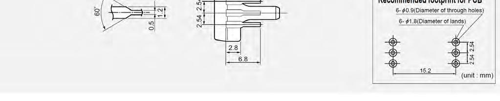
3 EH0110.pdf FPN Data sheet Sensing element Gauge Outline dimensions 2

4 EH0110.pdf FPN Data sheet Sensing element Gauge Connection diagram Output characteristics Output voltage mv Output span voltage Offset voltage Rated pressure 0 Rated pressure Atomospheric pressure Note ; Pressure Please read instruction Notes before using the sensor. Fujikura reserves the right to change specifications without notice. If you have any questions regarding technical issues or specifications, please contact us. Sensor Engineering Department 51 Kiba 1chome, Kotoku, Tokyo , Japan Phone +81(0) sensor@fujikura.co.jp 3
5 EH0110.pdf FGN Data sheet Sensing element Gauge Features Applications Surface mount package Home use NonInvasive Blood Pressure (NIBP) monitors Vacuum cleaner Washing machine Part number for ordering FGN6 07P G SR Terminal leads configuration Surface mount package Model Length of the pressure port 6 6mm Pressure type Rated Pressure (PSI) G Gauge Pressure Weight (grams) RoHS compliance 0.35 Measurable pressure range() Part number for ordering FGN602PGSR FGN605PGSR FGN607PGSR Specifications Model 602PG 605PG 607PG Recommended operating conditions Pressure type Gauge pressure Rated pressure Measurable pressure range Temperature range 0 50 Pressure media Noncorrosive gases only (No liquid) Excitation current (Constant) 1.5 Absolute maximum rating Maximum load pressure Twice of rated pressure Maximum excitation current 3.0 Operating temperature 0 80 Storage temperature Operating humidity (Non dew condition) Electric characteristics (Drive Current 1.5mA constant,ambient temperature Ta=25) Output span voltage (at 0 rated pressure Offset voltage ±25 (at 0) Bridge resistance Response time 2 (for the reference Accuracy TSO* ±10 ±8 TCS* Linearity ±0.6 ±0.3 Pressure hysteresis ±1.0 ±0.7 *TSO Temperature sensitivity of offset voltage *TCS Temperature coefficient of output span voltage *Temperature range from 050 deg C 1 Unit madc madc %RH mv mv Ω msec %FS/0 50 %FS/0 50 %FS %FS
6 EH0110.pdf FGN Data sheet Sensing element Gauge Outline dimensions FGN 2φ1.1 Connection diagram 2
7 EH0110.pdf FGN Data sheet Sensing element Gauge Output characteristics Output voltage mv Output span voltage Offset voltage Rated pressure 0 Rated pressure Atomospheric pressure Note ; Pressure Please read instruction Notes before using the sensor. Fujikura reserves the right to change specifications without notice. If you have any questions regarding technical issues or specifications, please contact us. Sensor Engineering Department 51 Kiba 1chome, Kotoku, Tokyo , Japan Phone +81(0) sensor@fujikura.co.jp 3
8 EH0110.pdf FPM Data sheet Sensing element Gauge Features Applications Industrial instrumentation Pressure switch, Pneumatic device Medical device Dualinline package (DIP) Part number for ordering FPM07P G R Terminal leadsdirection Model No Mark Rated Pressure (PSI) Pressure type G Gauge Pressure R Weight (grams) RoHS compliance 1.1 Measurable pressure range() Part number for ordering FPM02PG FPM05PG FPM07PG FPM15PG FPM30PG FPM50PG FPM70PG FPM120PG FPM02PGR FPM05PGR FPM07PGR FPM15PGR FPM30PGR FPM50PGR FPM70PGR FPM120PGR Specifications Model 02PG Recommended operating conditions Pressure type Rated pressure Measurable pressure range PG 07PG Temperature range Pressure media Excitation current (Constant) 15PG 30PG 50PG Gauge pressure Noncorrosive gases only (No liquid) PG 120PG Unit madc Absolute maximum rating 1.5 times of rating pressure Twice of rated pressure Maximum load pressure Maximum excitation current Operating temperature Storage temperature Operating humidity (Non dew condition) madc %RH Electric characteristics Drive Current 1.5mA constant, ambient temperature Ta=25 Output span voltage Offset voltage Bridge resistance Response time Accuracy TSO* TCS* Linearity Pressure hysteresis ±0.5 ± (at 0 rated pressure) ±20 (at 0) (for the reference) ±5 2.5 ±0.3 ±0.2 *TSO Temperature sensitivity of offset voltage *TCS Temperature coefficient of output span voltage *Temperature range from 050 deg C 1 ±0.5 ±0.6 ±0.4 mv mv Ω msec %FS/ 0 50 %FS %FS
9 EH0110.pdf FPM Data sheet Sensing element Gauge Outline dimensions 2
10 EH0110.pdf FPM Data sheet Sensing element Gauge Connection diagram Output characteristics 02PG 07PG 15PG 120PG Output voltage mv Output voltage mv Output span voltage Offset voltage Rated pressure Output span voltage Offset voltage Rated pressure Pressure Pressure Atomospheric pressure Note ; Rated pressure Atomospheric pressure Please read instruction Notes before using the sensor. Fujikura reserves the right to change specifications without notice. If you have any questions regarding technical issues or specifications, please contact us. Sensor Engineering Department 51 Kiba 1chome, Kotoku, Tokyo , Japan Phone +81(0) sensor@fujikura.co.jp 3
11 EH0110.pdf FPMA Data sheet Sensing element Absolute Features Applications Barometric pressure measurable Dualinline package (DIP) Industrial instrumentation Medical device Barometer, Altimeter Altitude compensation Part number for ordering FPM15P A R Terminal leadsdirection Model Rated Pressure (PSI) No Mark Pressure type A Absolute pressure R Weight (grams) RoHS compliance 1.5 Measurable pressure range( abs) Part number for ordering FPM15PA FPM15PAR Specifications Model FPM15PA FPM15PAR Recommended operating conditions Pressure type Absolute pressure Rated pressure Measurable pressure range Temperature range 0 50 Pressure media Noncorrosive gases only (No liquid) Excitation current (Constant) 1.5 Absolute maximum rating Maximum load pressure Twice of rated pressure Maximum excitation current 3.0 Operating temperature Storage temperature Operating humidity (Non dew condition) Electric characteristics (Drive Current 1.5mA constant,ambient temperature Ta=25) Output span voltage (at abs) Offset voltage (at abs) Bridge resistance Response time 2 (for the reference Accuracy TSO* ±3 TCS* 2.5 Linearity ±0.3 Pressure hysteresis ±0.2 *TSO Temperature sensitivity of offset voltage *TCS Temperature coefficient of output span voltage *Temperature range from 050 deg C 1 Unit abs abs madc madc %RH mv mv Ω msec %FS/0 50 %FS/0 50 %FS %FS
12 EH0110.pdf FPMA Data sheet Sensing element Absolute Outline dimensions 2
 Please read instruction Notes before using the sensor. Fujikura reserves the right to change specifications without notice.")
13 EH0110.pdf FPMA Data sheet Sensing element Absolute Connection diagram Output characteristics Output voltage mv Offset voltage Output span voltage Atomospheric pressure Note ; Pressure( abs) Please read instruction Notes before using the sensor. Fujikura reserves the right to change specifications without notice. If you have any questions regarding technical issues or specifications, please contact us. Sensor Engineering Department 51 Kiba 1chome, Kotoku, Tokyo , Japan Phone +81(0) sensor@fujikura.co.jp 3
14 EH0110.pdf FGM Data sheet Sensing element Gauge Features Applications Surface mount package Industrial instrumentation Pressure switch, Pneumatic device Medical device Part number for ordering FGM6 07P G SR Terminal leads configuration Surface mount package Model Length of the pressure port 3 3mm 6 6mm Measurable pressure range() Pressure type Rated Pressure (PSI) G Gauge Pressure Weight (grams) Weight (grams) Part number for ordering 3mm pressure port 6mm pressure port FGM302PGSR FGM602PGSR FGM605PGSR FGM305PGSR FGM307PGSR FGM607PGSR FGM315PGSR FGM615PGSR FGM330PGSR FGM630PGSR FGM350PGSR FGM650PGSR FGM370PGSR FGM670PGSR FGM3120PGSR FGM6120PGSR RoHS compliance Specifications Model 02PG Recommended operating conditions Pressure type Rated pressure Measurable pressure range PG 07PG Temperature range Pressure media Excitation current (Constant) Absolute maximum rating 15PG 30PG 50PG Gauge pressure Noncorrosive gases only (No liquid) PG 120PG Maximum excitation current Operating temperature Storage temperature Operating humidity madc 1.5 times of rating pressure Twice of rated pressure Maximum load pressure Unit (Non dew condition) madc %RH Electric characteristics Drive Current 1.5mA constant, ambient temperature Ta=25 Output span voltage Offset voltage Bridge resistance Response time Accuracy TSO* TCS* Linearity Pressure hysteresis ±0.5 ± (at 0 rated pressure) ±20 (at 0) (for the reference) ±5 2.5 ±0.3 ±0.2 *TSO Temperature sensitivity of offset voltage *TCS Temperature coefficient of output span voltage *Temperature range from 050 deg C 1 ±0.5 ±0.6 ±0.4 mv mv Ω msec %FS/ 0 50 %FS %FS
15 EH0110.pdf FGM Data sheet Sensing element Gauge Outline dimensions 2φ1.1 2
16 EH0110.pdf FGM Data sheet Sensing element Gauge Connection diagram Output characteristics 302PG 307PG 602PG 607PG 315PG 3120PG 615PG 6120PG Output voltage mv Output voltage mv Output span voltage Offset voltage Rated pressure Output span voltage Offset voltage Rated pressure Pressure Pressure Atomospheric pressure Note ; Rated pressure Atomospheric pressure Please read instruction Notes before using the sensor. Fujikura reserves the right to change specifications without notice. If you have any questions regarding technical issues or specifications, please contact us. Sensor Engineering Department 51 Kiba 1chome, Kotoku, Tokyo , Japan Phone +81(0) sensor@fujikura.co.jp 3
17 EH0110.pdf FDM Data sheet Sensing element Differential Features Applications Differential pressure Surface mount package Part number for ordering FDM07P D Industrial instrumentation Pressure switch, Pneumatic device Medical device SR Terminal leads configuration Model Surface mount package Pressure type D Differential pressure Rated Pressure (PSI) Weight (grams) RoHS compliance 1.2 Measurable pressure range() Part number for ordering FDM02PDSR FDM05PDSR FDM07PDSR FDM15PDSR FDM30PDSR FDM50PDSR FDM70PDSR FDM120PDSR Specifications Model 02PD Recommended operating conditions Pressure type Rated pressure Measurable pressure range Temperature range Pressure media Excitation current (Constant) Absolute maximum rating Maximum differential pressure **1 05PD 07PD PD 30PD 50PD Differential pressure Noncorrosive gases only (No liquid) PD 120PD madc 1.5 times of rating pressure Twice of rated pressure Port1 Maximum load pressure Port2 Maximum load pressure Maximum excitation current Operating temperature Storage temperature Operating humidity Unit (Non dew condition) madc %RH Electric characteristics Drive Current 1.5mA constant, ambient temperature Ta=25 Output span voltage **2 Offset voltage Bridge resistance Response time Accuracy TSO* TCS* Linearity Pressure hysteresis ±0.5 ± (at 0 rated pressure) ±20 (at 0) (for the reference) ±5 2.5 ±0.3 ±0.2 ±0.5 ±0.6 ±0.4 *TSO Temperature sensitivity of offset voltage *TCS Temperature coefficient of output span voltage *Temperature range from 050 deg C **1 Port1 pressure >Port2 pressure, Port2 pressure reference pressure **2 Output refers to pressure at pressure port2. 1 mv mv Ω msec %FS/ 0 50 %FS %FS
18 EH0110.pdf FDM Data sheet Sensing element Differential Outline dimensions Connection diagram 2
19 EH0110.pdf FDM Data sheet Sensing element Differential Output characteristics Output voltage mv Output span voltage Offset voltage Rated pressure 0 Rated pressure Atomospheric pressure Pressure Pressure() =Port1 pressure Port2 pressure (Port1 pressure >Port2 pressure) Output refers to pressure at pressure port2. Note ; Please read instruction Notes before using the sensor. Fujikura reserves the right to change specifications without notice. If you have any questions regarding technical issues or specifications, please contact us. Sensor Engineering Department 51 Kiba 1chome, Kotoku, Tokyo , Japan Phone +81(0) sensor@fujikura.co.jp 3

20 EH0110.pdf FHM Data sheet Sensing element Gauge Features Applications Horizonral pressure port Industrial instrumentation Pressure switch, Pneumatic device Medical device Part number for ordering FHM07P G R Terminal leadsdirection Model Rated Pressure (PSI) No Mark Pressure type G Gauge Pressure R Weight (grams) RoHS compliance 0 6 Measurable pressure range() Part number for ordering FHM02PG FHM05PG FHM07PG FHM15PG FHM30PG FHM50PG FHM70PG FHM120PG FHM02PGR FHM05PGR FHM07PGR FHM15PGR FHM30PGR FHM50PGR FHM70PGR FHM120PGR Specifications Model 02PG Recommended operating conditions Pressure type Rated pressure Measurable pressure range PG 07PG Temperature range Pressure media Excitation current (Constant) Absolute maximum rating 15PG 30PG 50PG Gauge pressure Noncorrosive gases only (No liquid) PG 120PG Maximum excitation current Operating temperature Storage temperature Operating humidity madc 1.5 times of rating pressure Twice of rated pressure Maximum load pressure Unit (Non dew condition) madc %RH Electric characteristics Drive Current 1.5mA constant, ambient temperature Ta=25 Output span voltage Offset voltage Bridge resistance Response time Accuracy TSO* TCS* Linearity Pressure hysteresis ±0.5 ± (at 0 rated pressure) ±20 (at 0) (for the reference) ±5 2.5 ±0.3 ±0.2 *TSO Temperature sensitivity of offset voltage *TCS Temperature coefficient of output span voltage *Temperature range from 050 deg C 1 ±0.5 ±0.6 ±0.4 mv mv Ω msec %FS/ 0 50 %FS %FS
21 EH0110.pdf FHM Data sheet Sensing element Gauge Outline dimensions 2
22 EH0110.pdf FHM Data sheet Sensing element Gauge Connection diagram Output characteristics 02PG 07PG 15PG 120PG Output voltage mv Output voltage mv Output span voltage Offset voltage Rated pressure Output span voltage Offset voltage Rated pressure Pressure Pressure Atomospheric pressure Note ; Rated pressure Atomospheric pressure Please read instruction Notes before using the sensor. Fujikura reserves the right to change specifications without notice. If you have any questions regarding technical issues or specifications, please contact us. Sensor Engineering Department 51 Kiba 1chome, Kotoku, Tokyo , Japan Phone +81(0) sensor@fujikura.co.jp 3
23 EH0110.pdf FAM Data sheet Sensing element Absolute Features Applications Barometric pressure measurable Surface mount package Industrial instrumentation Medical device Barometer, Altimeter Altitude compensation Part number for ordering FAM15P A SR Terminal leads configuration Model Rated Pressure (PSI) Surface mount package Pressure type A Absolute pressure Weight (grams) RoHS compliance 0.3 Measurable pressure range( abs) Part number for ordering FAM15PASR Specifications Model FAM15PASR Recommended operating conditions Pressure type Absolute pressure Rated pressure Measurable pressure range Temperature range 0 50 Pressure media Noncorrosive gases only (No liquid) Excitation current (Constant) 1.5 Absolute maximum rating Maximum load pressure Twice of rated pressure Maximum excitation current 3.0 Operating temperature Storage temperature Operating humidity (Non dew condition) Electric characteristics (Drive Current 1.5mA constant,ambient temperature Ta=25) Output span voltage (at abs) Offset voltage (at abs) Bridge resistance Response time 2 (for the reference Accuracy TSO* ±3 TCS* 2.5 Linearity ±0.3 Pressure hysteresis ±0.2 *TSO Temperature sensitivity of offset voltage *TCS Temperature coefficient of output span voltage *Temperature range from 050 deg C 1 Unit abs abs madc madc %RH mv mv Ω msec %FS/0 50 %FS/0 50 %FS %FS
24 EH0110.pdf FAM Data sheet Sensing element Absolute Outline dimensions Connection diagram 2
25 EH0110.pdf FAM Data sheet Sensing element Absolute Output characteristics Output voltage mv Offset voltage Output span voltage Atomospheric pressure Note ; Pressure( abs) Please read instruction Notes before using the sensor. Fujikura reserves the right to change specifications without notice. If you have any questions regarding technical issues or specifications, please contact us. Sensor Engineering Department 51 Kiba 1chome, Kotoku, Tokyo , Japan Phone +81(0) sensor@fujikura.co.jp 3
 Home")
26 EH0110.pdf XFPN Data sheet Preamplified 5V Excitation Gauge Features Applications Onchip amplification and temperature compensations Precalibration of offset voltage and span Dualinline package (DIP) Home use NonInvasive Blood Pressure (NIBP) monitors Vacuum cleaner Washing machine Part number for ordering XFPN025KP G R Terminal leadsdirection Model No Mark Rated Pressure Pressure type () G Gauge(Positive pressure) GV Gauge Pressure(Negative pressure) R Weight (grams) RoHS compliance 1.2 Measurable pressure range() Part number for ordering XFPN03PGV XFPN100KPGV XFPN025KPG XFPN050KPG XFPN100KPG XFPN200KPG XFPN03PGVR XFPN100KPGVR XFPN025KPGR XFPN050KPGR XFPN100KPGR XFPN200KPGR Specifications Model 03PGV Recommended operating conditions Pressure type Rated pressure Measurable pressure range Temperature range Pressure media Supply voltage constant Absolute maximum rating Maximum load pressure Maximum excitation voltage Operating temperature Storage temperature Operating humidity 100KPGV KPG 050KPG 100KPG 200KPG Gauge pressure Noncorrosive gases only (No liquid) 5±0.25 Twice of rated pressure (Non dew condition) Electrical characteristics (Excitation voltage Vcc=5.0V constant,ambient temperature Ta=25) Power consumption Output impedance Source current Sink current Response time Output span voltage Offset voltage * Output voltage at full scale * Accuracy * 10mA max. 10Ω max. 0.2mA max. 2mA max. 2 (for the reference) ±0.1 (at 0 ) 4.5±0.1 (at rated pressure) ±5.0 * Excluding input voltage error. 1 Unit VDC VDC RH ma Ω ma ma msec V V V %FS/0 50
27 EH0110.pdf XFPN Data sheet Preamplified 5V Excitation Gauge Outline dimensions 2
28 EH0110.pdf XFPN Data sheet Preamplified 5V Excitation Gauge Connection diagram View from Lavel Marking Transfer Function Vout = Vs ( P α+β) ± (Pressure Error Temperature Error Multiplier α Vs) Vs=Vcc=5.0V P= Input pressure() Model XFPN03PGV XFPN100KPGV XFPN025KPG XFPN050KPG XFPN100KPG XFPN200KPG XFPN03PGVR XFPN100KPGVR XFPN025KPGR XFPN050KPGR XFPN100KPGR XFPN200KPGR Measurable pressure range() T emperature Error Multiplier 3 α β Pressure Error (
29 EH0110.pdf XFPN Data sheet Preamplified 5V Excitation Gauge Output characteristics Output voltage mv Output voltage at full scale 4.5V Output span voltage Offset voltage 0.5V 0 Atomospheric pressure Note ; Rated pressure Pressure Please read instruction Notes before using the sensor. Fujikura reserves the right to change specifications without notice. If you have any questions regarding technical issues or specifications, please contact us. Sensor Engineering Department 51 Kiba 1chome, Kotoku, Tokyo , Japan Phone +81(0) sensor@fujikura.co.jp 4

30 EH0110.pdf XFGN Data sheet Preamplified 5V Excitation Gauge Features Applications Onchip amplification and temperature compensations Precalibration of offset voltage and span Surface mount package Home use NonInvasive Blood Pressure (NIBP) monitors Vacuum cleaner Washing machine Part number for ordering XFGN6 025KP G SR Terminal leads configuration Model Surface mount package Length of the pressure port 6 6mm Rated Pressure Pressure type () G Gauge(Positive pressure) GV Gauge Pressure(Negative pressure) Weight (grams) RoHS compliance 0.35 Measurable pressure range() Part number for ordering XFGN603PGVSR XFGN6100KPGVSR 0 25 XFGN6025KPGSR 0 50 XFGN6050KPGSR XFGN6100KPGSR XFGN6200KPGSR Specifications Model 603PGV Recommended operating conditions Pressure type Rated pressure Measurable pressure range Temperature range Pressure media Supply voltage constant Absolute maximum rating Maximum load pressure Maximum excitation voltage Operating temperature Storage temperature Operating humidity 6100KPGV KPG 6050KPG 6100KPG Gauge pressure Noncorrosive gases only (No liquid) 5±0.25 Twice of rated pressure (Non dew condition) Electrical characteristics (Excitation voltage Vcc=5.0V constant,ambient temperature Ta=25) Power consumption Output impedance Source current Sink current Response time Output span voltage Offset voltage * Output voltage at full scale * Accuracy * 10mA max. 10Ω max. 0.2mA max. 2mA max. 2 (for the reference) ±0.1 (at 0 ) 4.5±0.1 (at rated pressure) ±5.0 * Excluding input voltage error KPG Unit VDC VDC RH ma Ω ma ma msec V V V %FS/0 50
31 EH0110.pdf XFGN Data sheet Preamplified 5V Excitation Gauge Outline dimensions XFGN 2φ1.1 Connection diagram View from Lavel Marking 2
 Model XFGN603PGVSR XFGN6100KPGVSR XFGN6025KPGSR XFGN6050KPGSR XFGN6100KPGSR XFGN6200KPGSR Measurable pressure range() 0 24.5 0 100 0 25 0 50 0 100 0 200 α β Pressure Error () 0.")

32 EH0110.pdf XFGN Data sheet Preamplified 5V Excitation Gauge Transfer Function Vout = Vs ( P α+β) ± (Pressure Error Temperature Error Multiplier α Vs) Vs=Vcc=5.0V P= Input pressure() Model XFGN603PGVSR XFGN6100KPGVSR XFGN6025KPGSR XFGN6050KPGSR XFGN6100KPGSR XFGN6200KPGSR Measurable pressure range() α β Pressure Error () T emperature Error Multiplier Output characteristics Output voltage mv Output voltage at full scale 4.5V Output span voltage Offset voltage 0.5V 0 Atomospheric pressure Note ; Rated pressure Pressure Please read instruction Notes before using the sensor. Fujikura reserves the right to change specifications without notice. If you have any questions regarding technical issues or specifications, please contact us. Sensor Engineering Department 51 Kiba 1chome, Kotoku, Tokyo , Japan Phone +81(0) sensor@fujikura.co.jp 3
33 EH0110.pdf XFPM Data sheet Preamplified 5V Excitation Gauge Features Applications Industrial instrumentation Pressure switch, Pneumatic device Medical device Onchip amplification and temperature compensations Precalibration of offset voltage and span Dualinline package (DIP) Part number for ordering XFPM025KP G R Terminal leadsdirection Model No Mark Rated Pressure KP MP MPa Pressure type R G Gauge(Positive pressure) GV Gauge Pressure(Negative pressure) GW Gauge Pressure(Positive/Negative pressure) Weight (grams) RoHS compliance 1.2 Measurable pressure range() Part number for ordering XFPM100KPGW XFPM100KPGV XFPM025KPG XFPM050KPG XFPM100KPG XFPM200KPG XFPM001MPG XFPM100KPGWR XFPM100KPGVR XFPM025KPGR XFPM050KPGR XFPM100KPGR XFPM200KPGR XFPM001MPGR Specifications 100KPGW Model Recommended operating conditions Pressure type Rated pressure Measurable pressure range Temperature range Pressure media Supply voltage constant ± KPGV KPG 050KPG 100KPG Gauge pressure Noncorrosive gases only (No liquid) 5± KPG 001MPG Unit VDC Absolute maximum rating Twice of rated pressure Maximum load pressure Maximum excitation voltage Operating temperature Storage temperature Operating humidity (Non dew condition) 1.5 times of rating pressure VDC %RH Electrical characteristics (Excitation voltage Vcc=5.0V constant,ambient temperature Ta=25) Power consumption Output impedance Source current Sink current Response time Output span voltage Offset voltage *1 Output voltage at full scale *1 Accuracy *1 *2 *4 *3 *5 10mA max. 10Ω max. 0.2mA max. 2mA max. 2 (for the reference) ± (at 0 ) 4.7± (at rated pressure) ±2.5 *1 Excluding input voltage error. *2 0.2±0.1125V(at 100 ) *3 0.2±0.1125V(at 0) *4 4.7±0.1125V(at +100) *5 4.7±0.1125V(at 100) 1 ma Ω ma ma msec V V V %FS/0 85
34 EH0110.pdf XFPM Data sheet Preamplified 5V Excitation Gauge Outline dimensions 2
35 EH0110.pdf XFPM Data sheet Preamplified 5V Excitation Gauge Connection diagram View from Lavel Marking Transfer Function Vout = Vs ( P α+β) ± (Pressure Error Temperature Error Multiplier α Vs) Vs=Vcc=5.0V P=Input pressure() Model XFPM100KPGW XFPM100KPGV XFPM025KPG XFPM050KPG XFPM100KPG XFPM200KPG XFPM001MPG XFPM100KPGWR XFPM100KPGVR XFPM025KPGR XFPM050KPGR XFPM100KPGR XFPM200KPGR XFPM001MPGR Measurable pressure range() Temperature Error Multiplier 3 α β Pressure Error ()
36 EH0110.pdf XFPM Data sheet Preamplified 5V Excitation Gauge Output characteristics Output voltage mv XFPM100KPGV XFPM025KPG XFPM050KPG XFPM100KPG XFPM200KPG XFPM001MPG XFPM100KPGVR XFPM025KPGR XFPM050KPGR XFPM100KPGR XFPM200KPGR XFPM001MPGR Output voltage at full scale 4.7V Output span voltage Offset voltage 0.2V Rated pressure 0 Pressure Atomospheric pressure XFPM100KPGW Output voltage mv XFPM100KPGWR Output voltage at full scale 4.7V Output span voltage Offset voltage 0.2V Atomospheric pressure Note ; Please read instruction Notes before using the sensor. Fujikura reserves the right to change specifications without notice. If you have any questions regarding technical issues or specifications, please contact us. Sensor Engineering Department 51 Kiba 1chome, Kotoku, Tokyo , Japan Phone +81(0) sensor@fujikura.co.jp 4 Pressure
37 EH0110.pdf XFPMA Data sheet Preamplified 5V Excitation Absolute Features Applications Barometric pressure measurable Onchip amplification and temperature compensations Precalibration of offset voltage and span Dualinline package (DIP) Industrial instrumentation Medical device Barometer, Altimeter Altitude compensation Part number for ordering XFPM115KP A R Terminal leadsdirection Model Rated Pressure () Pressure type A Absolute pressure No Mark R Weight (grams) RoHS compliance 1.5 Measurable pressure range( abs) Part number for ordering XFPM115KPA XFPM115KPAR Specifications Model XFPM115KPA XFPM115KPAR Recommended operating conditions Pressure type Absolute pressure Rated pressure 115 Measurable pressure range Temperature range 0 85 Pressure media Noncorrosive gases only (No liquid) Supply voltage constant 5±0.25 Absolute maximum rating Maximum load pressure Twice of rated pressure Maximum excitation voltage 8 Operating temperature Storage temperature Operating humidity (Non dew condition) Electrical characteristics (Excitation voltage Vcc=5.0V constant,ambient temperature Ta=25) Power consumption 10mA max. Output impedance 10Ω max. Source current 0.2mA max. Sink current 2mA max. Response time 2 (for the reference) Output span voltage 4.5 Offset voltage * 0.2± (at 15 abs ) Output voltage at full scale * 4.7± (at 115 abs ) Accuracy * ±2.5 * Excluding input voltage error. 1 Unit abs abs VDC VDC %RH ma Ω ma ma msec V V V %FS/0 85


38 EH0110.pdf XFPMA Data sheet Preamplified 5V Excitation Absolute Outline dimensions 2
 ± (Pressure Error")
39 EH0110.pdf XFPMA Data sheet Preamplified 5V Excitation Absolute Connection diagram View from Lavel Marking Transfer Function Vout = Vs ( P α+β) ± (Pressure Error Temperature Error Multiplier α Vs) Vs=Vcc=5.0V P= Input pressure( abs) α β Pressure Error () T emperature Error Multiplier 3
40 EH0110.pdf XFPMA Data sheet Preamplified 5V Excitation Absolute Output characteristics Output voltage mv Output voltage at full scale 4.7V Output span voltage Offset voltage 0.2V 15 abs 115 abs Pressure( abs) Note ; Please read instruction Notes before using the sensor. Fujikura reserves the right to change specifications without notice. If you have any questions regarding technical issues or specifications, please contact us. Sensor Engineering Department 51 Kiba 1chome, Kotoku, Tokyo , Japan Phone +81(0) sensor@fujikura.co.jp 4
41 EH0413.pdf DATE 29 March, 2013 No. V70001 Messrs. SPECIFICATION Model: AP2, AG2 Pressure Sensor Preliminary Edition Project: Distributor: Ver This document has a possibility to be revised without notice. Reference: Yoshiyuki Uchiumi, Application Engineer Sensor Department Fujikura Ltd.
42 EH0413.pdf Preliminary Edition Ver This document has a possibility to be revised without notice. 1. V70001 General This document describes the specifications of Fujikura Pressure Sensors, AP2 and AG2 series. 2. Principle Fujikura Pressure Sensor is composed of a silicon piezoresistive pressure sensing chip and a signal conditioning integrated circuit. The lowlevel signal from the sensing chip is amplified, temperature compensated, calibrated, and finally converted to a highlevel output signal that is proportional to the applied pressure. 3. Device Lineup This device has the following lineup. Pressure Supply Model Accuracy Type Voltage AP2 or AG2 4. Gauge 5.0Vdc or 3.3Vdc ±1.5%FS 3.0Vdc ±2.0%FS Pressure Range () Same as the above RoHS This device is compliant with the Restriction of the use of certain Hazardous Substances in Electrical and Electronic Equipment (RoHS). Table shown below is revision records of this specification Rev. Est. Date Name Comment 1 of 12 Mark
43 EH0413.pdf Preliminary Edition Ver This document has a possibility to be revised without notice. 5. V70001 Block Diagram and Pin Connections 3.0V, 3.3 or 5Vdc Pin 3 VDD VDD Temperature Sensor Sensor Bridge 0.1µF MUX ADC DSP DAC Preamplifier EEPROM Pin 1 VSS Buffer Oscillator Power On Reset Pin 6 NC Pin 5 NC Pin 4 NC Pin 2 VOUT Pin No. Pin Name I/O Type VSS VOUT VDD NC NC NC O Analog Function Common voltage connection Analog output Power supply connection Notes: *1) 0.1µF capacitance is recommended to connect VDD Pin 3 with VSS Pin 1. *2) Pin 4, 5 and 6 must be open. 2 of 12 *1 *2 *2 *2
44 EH0413.pdf Preliminary Edition Ver This document has a possibility to be revised without notice. 6. V70001 Device Name Code The device name code is consisted of Sensor code, Pressure code and Packing style. For the exact ordering device number, please refer to Section 16 Ordering Information. Sensor Code Pressure Code AP2 0 N 025 K G TP Model AP2 : DIP (Dual Inline Package) AG2 : SMD (Surface Mount Device) Packing style Blank : Trays TP : Tape & Reel STICK : Sticks Supply voltage 0 : 5.0V 1 : 3.3V 2 : 3.0V Pressure type G : Gauge/Positive V : Gauge/Negative W : Gauge/Bipressure Pin direction for AP2 N : Normal R Unit K M : Opposite Pressure value 025 : : : : : 1MPa Port length for AG2 3 : 3mm 6 7. : 6mm Absolute Maximum Ratings *1 Symbol Pressure Code Item Maximum Load Pressure : : MPa Rating Unit 025KG KG KG KG Pmax MPa 100KV KW ± MG Maximum Input Voltage VDD 6 Vdc Operating Temperature Topt 40 ~ +125 deg. C Storage Temperature Tstg 40 ~ +125 deg. C Note: *1) Absolute maximum ratings are the limits that the device will withstand without damage. 3 of 12
45 EH0413.pdf Preliminary Edition Ver This document has a possibility to be revised without notice. 8. V70001 General Specifications Sensor Code Item Symbol AP20x AG20x AP22x AG22x Unit 3.3± ±0.15 Vdc Supply Voltage VDD Type of Pressure Gauge pressure *2 Pressure Media Noncorrosive gases *3 Pressure Range Popt Refer to Section 9 Compensated Temperature 5.0±0.25 AP21x AG21x *1 0 ~ +85 deg. C *4 Operating Humidity Hopt 30~85 (noncondensing) %RH *5 Storage Humidity Hstg 30~85 (noncondensing) %RH *5 Dielectric Strength Leakage current 1mA maximum, AC500V, 1minute *6 100MΩ minimum (DC500V) *7 Insulation Resistance Notes: *1) Output voltage (Vout) is not perfectly ratiometric with Supply voltage (VDD). *2) Gauge pressure is defined as the difference between the pressure applied to the pressure port and an ambient pressure of the device. *3) Ensure the pressure media contains no particulates. The device is not compatible with liquids. *4) Please also refer to Section 12 Transfer Function. *5) Do not wet the device with dew. *6) Dielectric strength is defined as the leakage current between all pins and the package with AC500, 1 minute. *7) Insulation resistance is defined as the resistance value between all pins and the package with DC500V. 9. Pressure Range Pressure Code Symbol Pressure Range Min. Typ. *1 Max. Unit 025KG KG MG 0 +1 MPa 100KV KW KG 200KG Popt Note: *1) Pressure range is defined as the measurable pressure range of the device. Do not expose intentionally beyond minimum Popt and maximum Popt. 4 of 12
46 EH0413.pdf Preliminary Edition Ver This document has a possibility to be revised without notice. 10. Electrical Characteristics Item Ambient temperature Ta=25deg. C Condition Sensor Code: AP20x, AG20x Span Voltage Non load resistor, Min. to max. Popt Non load resistor, Min. Popt 100KV: Max. Popt Sensor Code: AP21x, AG21x Full Scale Voltage Span Voltage Non load resistor, Min. to max. Popt Accuracy 0 to 85 deg. C, Non load resistor Non load resistor, Min. Popt 100KV: Max. Popt Sensor Code: AP22x, AG22x Full Scale Voltage Span Voltage Non load resistor, Min. to max. Popt Accuracy 0 to 85 deg. C, Non load resistor Response Time Non load resistor, Min. Popt 100KV: Max. Popt for reference Sampling Frequency Load Resistor V *1, 2 Vfs V *3 *4 SV 4.5 V %FS V Vrso 2.5 mv *7 Ic 3 madc *8 Voff V *1, 2 Vfs V *3 SV 2.7 V *4 *5, %FS V Vrso 1.7 mv *7 Ic 2 madc *8 Voff V *1, 2 Vfs V *3 SV 2.7 V *4 *5, %FS V Vrso 1.5 mv *7 Ic 2 madc *8 Error Output Resolution Consumption Current (VDD = 3.0Vdc) Non load resistor, Min. Popt 100KV: Max. Popt Non load resistor, Max. Popt 100KV: Min. Popt Offset Voltage Voff Error Output Resolution Consumption Current Unit (VDD = 3.3Vdc) Non load resistor, Min. Popt 100KV: Max. Popt Non load resistor, Max. Popt 100KV: Min. Popt Offset Voltage Max. Error 0 to 85 deg. C, Non load resistor Output Resolution Consumption Current Rating Typ. (VDD = 5Vdc) Full Scale Voltage Accuracy Min. Symbol Non load resistor, Min. Popt 100KV: Max. Popt Non load resistor, Max. Popt 100KV: Min. Popt Offset Voltage V70001 VOUT VSS or VDD VOUT *5, 6 tr 1 2 msec. *9 fs 1 khz *10 RL 2.5 kohm *11 Notes; *1) Offset voltage (Voff) is defined as the output voltage at minimum Popt. However Offset voltage (Voff) of 100KV is defined as the output voltage of maximum Popt. *2) Offset error is calibration error of Offset voltage (Voff) at production. It does not include Long term offset drift. It would be suggested that application has Autozeroing function. *3) Full scale voltage (Vfs) is defined as the output voltage at maximum Popt. However Full scale voltage (Vfs) of 100KV is defined as the output voltage of minimum Popt. *4) Output span voltage (SV) is defined as the voltage difference between Offset voltage (Voff) and Full scale voltage (Vfs). 5 of 12
47 EH0413.pdf Preliminary Edition Ver This document has a possibility to be revised without notice. V70001 *5) Accuracy consists of the following: Nonlinearity Temperature errors over the temperature range 0 to 85 degree C Pressure hysteresis Calibration errors of sensitivity and offset *6) The unit of Accuracy %FS is defined as a percent error by Span voltage (SV). *7) Output voltage (Vout) is generated by the internal digital to analog converter. Therefore the output voltage has Output resolution (Vrso). Resolution in pressure is calculated as below: Pressure resolution = Vrso Pressure range (Min. to Max.) SV *8) Consumption current (Ic) is increased depending on the value of Load resistor (RL). *9) Response time (tr) is defined as the time for the change in Output voltage (Vout) from 10% to 90% or from 90% to10% of its final value when the input pressure makes a step change. Input Pressure 0 90% of Full Scale Voltage Output Voltage 10% of Full Scale Voltage Offset Voltage tr tr *10) Output voltage (Vout) is sampled and held by the internal sampling / hold block. Sampling frequency (fs) is 1 khz. The output voltage is changed stepwise every approximately 1millisecond. Input pressure Output voltage fs = 1msec *11) The value of Load resistor (RL) affects Consumption current (Ic). 6 of 12 1 = 1 msec 1 khz
48 EH0413.pdf Preliminary Edition Ver This document has a possibility to be revised without notice. V Output versus Input Pressure Pressure Code 025KG, 050KG, 100KG, 200KG,001MG VDD = 5.0 Vdc Temp. = 0 to 85 Vful: 4.7V Error: ±1.5%FS Voff: 0.2V Max. Popt: 25, 50, 100, 200, 1MPa Voff: 0.3V Output Vspan: 2.7V Voff: 0.3V Max. Popt: 25, 50, 100, 200, 1MPa Max. Popt: 0 Input Pressure VDD = 3.0 Vdc Temp. = 0 to 85 Voff: 0.15V Output Error: ±2.0%FS Vspan: 2.7V Voff: 0.15V Min. Popt: 0 Input Pressure Max. Popt: 25, 50, 100, 200, 1MPa Max. Popt: +100 Min. Popt: 100 VDD = 3.0 Vdc Temp. = 0 to 85 Vful: 2.85V Vspan: 2.7V Vspan: 2.7V 1.65V Input Pressure VDD = 3.0 Vdc Temp. = 0 to 85 Error: ±2.0%FS Error: ±1.5%FS Voff: 0.3V Min. Popt: 100 Input Pressure Output VDD = 3.3 Vdc Temp. = 0 to 85 Vful: 3.0V Error: ±1.5%FS Max. Popt: +100 Input Pressure VDD = 3.3 Vdc Temp. = 0 to 85 Output Output Vspan: 2.7V Vspan: 4.5V Min. Popt: 100 Vful: 3.0V Min. Popt: 0 AP22x AG22x Max. Popt: 0 Input Pressure VDD = 3.3 Vdc Temp. = 0 to 85 Error: ±1.5%FS Error: ±1.5%FS 2.45V Voff: 0.2V Min. Popt: 100 Input Pressure Vful: 2.85V Vspan: 4.5V Output Vspan: 4.5V Min. Popt: 0 AP21x AG21x VDD = 5.0 Vdc Temp. = 0 to 85 Vful: 4.7V Error: ±1.5%FS Voff: 0.2V Vful: 3.0V 100KW VDD = 5.0 Vdc Temp. = 0 to 85 Output AP20x AG20x Output Vful: 4.7V 100KV Output Sensor Code Vful: 2.85V Error: ±2.0%FS 1.5V Vspan: 2.7V Voff: 0.15V Min. Popt: 100 Input Pressure 7 of 12 Max. Popt: 0 Min. Popt: 100 Input Pressure Max. Popt: +100
49 EH0413.pdf Preliminary Edition Ver This document has a possibility to be revised without notice. V Transfer Function Vout = VDD ((P α) + β) ± (Pressure Error Temperature Error Multiplier α Vs) Parameters Parameter P () VDD (*1) Sensor Code AP20x AG20x Pressure Code Pressure Error () 0 ~ +25 9/250 1/ KG 0 ~ +50 9/500 1/ KG 0 ~ /1000 1/ ~ /2000 1/ ~ / / /1000 9/2000 1/25 49/ KG 5.0±0.25V 100KV 100KW 100 ~ ~ KG 0 ~ /9075 1/ KG 0 ~ / / KG 0 ~ / / ~ / / ~ / / /3630 1/ KG 3.3±0.165V 001MG AP22x AG22x β 025KG 001MG AP21x AG21x α 100KV 100 ~ 0 100KW 100 ~ /6600 1/ KG 0 ~ +25 9/250 1/ KG 0 ~ +50 9/500 1/ KG 0 ~ /1000 1/ ~ ~ /2000 9/ /20 1/ KG 001MG 3.0±0.15V 100KV 100 ~ 0 9/1000 1/ KW 100 ~ /2000 1/2 4 *1) Output voltage (Vout) is not perfectly ratiometric with the supply voltage (VDD). Temperature Error Multiplier 4 Error Multiplier Temperature () 8 of
50 EH0413.pdf Preliminary Edition Ver This document has a possibility to be revised without notice. V Device Marking AG2 AP2 Production Lot YMDD AP20 025K YMDD Sensor Code AG20 050K Pressure Code Custom ID Items Production Lot Y M DD Sensor Code Marking Last digit of Production year Production month Production date 0~9 1, 2, 3 ~ 8, 9, X=Oct., Y=Nov., Z=Dec. 01~31 *1 AP20x AP21x AP22x AG20x AG21x AG22x AP20 AP21 AP22 AG20 AG21 AG22 025KG 025K 050K Pressure Code 050KG 100KG 100K 200K 200KG 001MG 001M 100V 100KV 100KW 100W If applicable Custom ID Notes: *1) Pin direction for AP2 or Port length for AG2 is not marked on the face plate. *2) Custom ID will be added when a product is customized for a customer. 9 of 12 *2
51 EH0413.pdf Preliminary Edition Ver This document has a possibility to be revised without notice. V Soldering Process Model Hand Soldering AP2xx AP2xx AP2xR AP2xR AG2xx AG2xx Wave Soldering Reflow Soldering Condition *1, 2 Temperature: 350 deg. C max. Soldering time: 3 seconds max. Temperature: 260 deg. C max. Soldering time: 5 seconds max. *1, 2 *1, 2, 3, 4 Soldering Profile Temperature() A C B D E Time A Ramp up B Preheating C Ramp up D Heating E Ramp down 2 to 4 deg. C / sec. 150 to 180 deg. C 60 to 120 sec. 2 to 4 deg. C / sec. Above 230 deg. C, 45 sec. max. 245 deg. C max., 10 sec. max. 2 to 4 deg. C / sec. Notes: *1) NEVER wash the device with any washing liquid. NEVER wash the device with any ultrasonic washing machine. *2) Do not put the solder and flux on the device s package. *3) Temperature means Surface temperature of the device s package. *4) Reflow soldering is within two times. 15. Dimensions and Weights Refer to the following drawing as attached. Sensor Code Dimension Drawing AP2xN AP2xR AG2x approx. 0.3 grams AG2x approx. 0.4 grams 10 of 12 Weight approx. 1.4 grams
52 EH0413.pdf Preliminary Edition Ver This document has a possibility to be revised without notice. V Ordering Information Model Package Supply Voltage Pin Direction Normal 5.0 Vdc Opposite Normal AP2 DIP 3.3 Vdc Opposite Normal 3.0 Vdc Opposite Packing Ordering Device Number Trays Sticks Trays Sticks Trays Sticks Trays Sticks Trays Sticks Trays Sticks AP20NAP20NAP20RAP20RAP21NAP21NAP21RAP21RAP22NAP22NAP22RAP22R Trays Tape & Reel Trays Tape & Reel Trays Tape & Reel Trays Tape & Reel Trays Tape & Reel Trays Tape & Reel AG203AG203AG206AG206AG213AG213AG216AG216AG223AG223AG226AG226 STICK STICK STICK STICK STICK STICK Qty./Packing TBD TBD TBD TBD TBD TBD TBD TBD TBD TBD TBD TBD Pcs/Tray Pcs/Stick Pcs/Tray Pcs/Stick Pcs/Tray Pcs/Stick Pcs/Tray Pcs/Stick Pcs/Tray Pcs/Stick Pcs/Tray Pcs/Stick Port Length 3mm 5.0 Vdc 6mm 3mm AG2 SMD 3.3 Vdc 6mm 3mm 3.0 Vdc 6mm Pressure 0 ~ 0 ~ 0 ~ 0 ~ 0 ~ 0 ~ 100 ~ Range MPa TP TP TP TP TP TP Pressure Code 025KG 050KG 100KG 200KG 001MG 100KV 100KW 17. Tape & Reel Information Reel Pin 6 Embossed carrier tape Feed direction Pin 1 Index 11 of 12 TBD TBD TBD TBD TBD TBD TBD TBD TBD TBD TBD TBD Pcs/Tray Pcs/Reel Pcs/Tray Pcs/Reel Pcs/Tray Pcs/Reel Pcs/Tray Pcs/Reel Pcs/Tray Pcs/Reel Pcs/Tray Pcs/Reel
53 EH0413.pdf Preliminary Edition Ver This document has a possibility to be revised without notice. V Footprint for PCB (for Reference) Sensor Code Footprint Hole for Pressure Port Diameter is depending on your design. 6 φ1.8 mm AP2xN 2.54 mm 6 φ0.9 mm 2.54 mm Land pads 15.2 mm 6 φ1.8 mm 2.54 mm 6 φ0.9 mm AP2xR 2.54 mm Land pads 15.2 mm 1.7 mm 1.4 mm 2.54 mm AG2x mm Land pads 9.4 mm 1.7 mm 2 φ1.1 mm (Holes for Projections) 1.4 mm 2.54 mm 6.0 mm 2.54 mm AG2x6 Land pads 6.0 mm 9.4 mm Notes: *1) These footprints are for reference. Please evaluate well these footprints, before your mass production. *2) When designing your PCB, please also refer to the outline diagrams. 12 of 12
54 EH0413.pdf
55 EH0413.pdf
56 EH0413.pdf
57 EH0413.pdf
58 We are here for you. Addresses and Contacts Sales Switzerland Postcode Liechtenstein Postcode Matthias Rüegg Ruhbergstrasse 32 CH9230 Flawil Raffael Favaretto Route d Oron 124 CH1673 Promasens Phone Mobile Fax Phone Mobile Fax matthias.rueegg@pewatron.com raffael.favaretto@pewatron.com Sales Austria Sales Germany Postcode Postcode Postcode Key Accounts Aerospace and Defence Dieter Hirthe Mühlweg 23 D71554 Weissach i.t. Kurt Stritzelberger Neumarkter Str. 86a D81673 Munich Claus Wübbena Vogelkamp 26 D26655 Westerstede Kurt Stritzelberger Neumarkter Str. 86a D81673 Munich Phone Mobile Fax Phone Mobile Fax Phone Mobile Fax Phone Mobile Fax dieter.hirthe@pewatron.com kurt.stritzelberger@pewatron.com claus.wuebbena@pewatron.com kurt.stritzelberger@pewatron.com PEWATRON AG Thurgauerstrasse 66 CH8052 Zurich Sales Other Countries / Product Management Sensors Power Supplies EComponents Physical Sensors Data Acquisition DCDC Converters Switching Power Supplies DCAC Inverters Current Sensors Man Machine Interface Measurement Probes Sebastiano Leggio Phone sebastiano.leggio@pewatron.com Sebastiano Leggio Phone sebastiano.leggio@pewatron.com Peter Felder Phone peter.felder@pewatron.com Phone Fax info@pewatron.com Geometrical Sensors Eric Letsch Phone eric.letsch@pewatron.com Supporting your great ideas

59 EH0713.pdf DATE 20 June, 2013 No. V70033 Messrs. SPECIFICATION Model: AP4, AG4 Pressure Sensor Preliminary Edition Project: Distributor: rev This document has a possibility to be revised without notice. Reference: Yoshiyuki Uchiumi, Application Engineer Sensor Department Fujikura Ltd.
60 EH0713.pdf Preliminary Edition rev This document has a possibility to be revised without notice. V70033 Table of Contents 1. General Principle Device Lineup RoHS Block Diagram and Pin Connections Device Name Code Absolute Maximum Ratings General Specifications Pressure Range Electrical Characteristics Communication Interface Communication Protocol Output versus Input Pressure Transfer Function Operating Sequence Device Marking Soldering Dimensions and Weights Ordering Information Tape & Reel Information Footprint for PCB (for Reference) Appendix: Dimension Drawing APxxN APxxR AGxx AGxx of 17
61 EH0713.pdf Preliminary Edition rev This document has a possibility to be revised without notice. 1. V70033 General This document describes the specifications of Fujikura Pressure Sensors, AP4 and AG4 series. 2. Principle Fujikura Pressure Sensor is composed of a silicon piezoresistive pressure sensing chip and a signal conditioning integrated circuit. The lowlevel signal from the sensing chip is amplified, temperature compensated, calibrated, and finally converted to digital data that is proportional to the applied pressure. 3. Device Lineup This device has the following lineup. Pressure Supply Model Accuracy Type Voltage AP4 or AG4 Gauge 5.0Vdc 3.3Vdc 3.0Vdc Pressure Range () ±1.5%FS Features Digital Output High Accuracy 4. RoHS This device is compliant with the Restriction of the use of certain Hazardous Substances in Electrical and Electronic Equipment (RoHS). Table shown below is revision records of this specification Rev. Est. Date Name Comment 2 of 17 Mark
62 EH0713.pdf Preliminary Edition rev This document has a possibility to be revised without notice. 5. V70033 Block Diagram and Pin Connections 3.0, 3.3 or 5.0Vdc Pin 4 VDD VDD Temperature Sensor 0.1µF Sensor Bridge MUX ADC DSP Communication Interface Pin 3 SCL Preamplifier Pin 2 SDA EEPROM Pin 5 VSS Pin 1 NC AG Index Index Pipe Oscillator Pin 6 NC Pin Assignment AP4 Rpu x 2 Power On Reset Pipe Pin No. Pin Name I/O Type NC SDA SCL VDD VSS NC I/O I Digital Digital Notes: *1) Put a 0.1µF capacitor between VDD Pin 4 and VSS Pin 5. *2) Pin 1 and 6 must be open. 3 of 17 Function Serial bidirectional data Serial clock input Power supply connection Common voltage connection *1 *2 *1
63 EH0713.pdf Preliminary Edition rev This document has a possibility to be revised without notice. 6. V70033 Device Name Code The device name code is consisted of Sensor code, Pressure code, Slave address core and Packing style. For the exact ordering device number, please refer to Chapter 19 Ordering Information. Sensor Code Pressure Code AP4 0 N 025 K G Model AP4 : DIP (Dual Inline Package) AG4 : SMD (Surface Mount Device) Packing style Blank : Tray TP : Tape & Reel STICK : Stick Supply voltage 0 : 5.0Vdc 1 : 3.3Vdc 2 : 3.0Vdc Slave address code Blank : 0x28(Default) 3 : 0x38 7 : 0x78 or Custom ID: if applicable Pin direction for AP2 N : Normal R Pressure type G : Gauge/Positive V : Gauge/Negative W : Gauge/Bipressure : Opposite Port length for AG2 3 : 3mm 6 STICK Unit K M : 6mm : : MPa Pressure value 025 : : : : : 1MPa 4 of 17
64 EH0713.pdf Preliminary Edition rev This document has a possibility to be revised without notice. 7. V70033 Absolute Maximum Ratings Min. Rating Typ. 025KG KG KG MG +1.5 MPa 100KV KW +200 Vdc Load Pressure Symbol Pressure Code Item 200KG Pmax+ Max. Supply Voltage VDDmax Voltage at Digital I/O pins Unit Vdiomax 0.3 VDD+0.3 Vdc Operating Temperature Topt deg. C Storage Temperature Tstg deg. C Note: *1) Absolute maximum ratings are the limits that the device will withstand without damage. 8. General Specifications Sensor Code Item Symbol AP40x AG40x AP42x AG42x Unit 3.3± ±0.15 Vdc Supply Voltage VDD Type of Pressure Gauge pressure *2 Pressure Media Noncorrosive gases *3 Pressure Range Popt Refer to Chapter 9 Compensated Temperature 5.0±0.25 AP41x AG41x *1 0 ~ +85 deg. C *4 Operating Humidity Hopt 30~85 (noncondensing) %RH *5 Storage Humidity Hstg 30~85 (noncondensing) %RH *5 Dielectric Strength Leakage current 1mA maximum, AC500V, 1minute *6 100MΩ minimum (DC500V) *7 Insulation Resistance Notes: *1) Supply (VDD) should be constant. *2) Gauge pressure is defined as the difference between the pressure applied to the pressure port and an atmospheric pressure of the device. *3) Ensure the pressure media contains no particulates. The device is not compatible with liquids. *4) Please also refer to Chapter 14 Transfer Function. *5) Do not wet the device with dew. *6) Dielectric strength is defined as the leakage current between all pins and the package with AC500, 1 minute. *7) Insulation resistance is defined as the resistance value between all pins and the package with DC500V. 5 of 17
65 EH0713.pdf Preliminary Edition rev This document has a possibility to be revised without notice. 9. V70033 Pressure Range Pressure Code Symbol Pressure Range Min. Typ. *1 Max. Unit KG 0 050KG KG MG 200KG Popt 0 +1 MPa 100KV KW Note: *1) Pressure range is defined as the measurable pressure range of the device. Do not expose intentionally beyond minimum Popt and maximum Popt. 10. Electrical Characteristics Ambient temperature Ta=25deg. C Item Condition Symbol Min. Rating Typ. Max. Unit Offset Pressure Data Min. Popt, 100KV: Max. Popt Doff Count *1, 2 Full Scale Pressure Data Max. Popt, 100KV: Min. Popt Dfs Count *3 Span Pressure Data Min. to max. Popt SD Count *4 Accuracy 0 to 85 deg. C Error %FS *5, 6 Ic 3 madc tr 2 msec. Consumption Current Response Time for reference Notes; *1) Offset pressure data (Doff) is defined as the pressure data at minimum Popt. In case of 100KV, Offset pressure data (Doff) is defined as the pressure data of maximum Popt. *2) Offset error is calibration error of Offset pressure data (Doff) at production. It does not include Long term offset drift. It would be suggested that applications have Autozeroing function. *3) Full scale pressure data (Dfs) is defined as the pressure data at maximum Popt. In case of 100KV, Full scale pressure data (Dfs) is defined as the pressure data of minimum Popt. *4) Span pressure data (SD) is defined as the pressure data difference between Offset pressure data (Doff) and Full scale pressure data (Dfs). *5) Accuracy consists of the following: Nonlinearity Temperature errors over the temperature range 0 to 85 degree C Pressure hysteresis Calibration errors of sensitivity and offset *6) The unit of Accuracy %FS is defined as a percent error by Span pressure data (SD). *7) Response time is defined as the time of 1 cycle measurement sequence. 6 of 17 *7
66 EH0713.pdf Preliminary Edition rev This document has a possibility to be revised without notice. V Communication Interface Ambient temperature Ta=25deg. C Item Condition Symbol Min. Rating Typ. Max. Unit I2CTM Interface Input Low Voltage VIL 0 Input High Voltage VIH 0.8 Output Low Voltage VOL Cmax Rpu 1 Load Capacitance Pin2 SDA, 400kHz Pullup Resistor Pin2 SDA, Pin3 SCL Slave address 7 bit *1 0.2 V 1 V 0.1 V 200 pf kω 0x28 Notes: *1) I2CTM is a trademark of NXP. *2) Slave address is available from 0x38 to 0x78 as optional. Please designate the slave address in the device name code. 12. Communication Protocol Item Slave Address [6:0] Pressure Data [13:8] Pressure Data [7:0] S R A A N S Measurement Packet S Start Condition R 6 Slave Address A ACK 13 Data Bit N NACK 7 of 17 Read (1) S Stop Condition 15 Status Bit *2
67 EH0713.pdf Preliminary Edition rev This document has a possibility to be revised without notice. 13. Output versus Input Pressure Pressure Code Output vs. Input pressure Temp. = 0 to KG, 050KG, 100KG, 200KG, 001MG Count Dfs: Error: ±1.5%FS SD: Doff: 819 Max. Popt: 25, 50, 100, 200, 1MPa Min. Popt: 0 Input Pressure Temp. = 0 to 85 Count Dfs: SD: Error: ±1.5%FS 100KV Doff: 819 Max. Popt: 0 Min. Popt: 100 Input Pressure Temp. = 0 to 85 Count Dfs: Error: ±1.5%FS SD: KW Doff: 819 Min. Popt: Input Pressure 8 of 17 Max. Popt: +100 V70033
68 EH0713.pdf Preliminary Edition rev This document has a possibility to be revised without notice. V Transfer Function Pressure Data (Count) = P α + β ± (Pressure Error Temperature Error Multiplier) Parameters Parameter P () Pressure Code α β Pressure Error (Count) 025KG 0 ~ / KG 0 ~ / KG 0 ~ / KG 0 ~ / MG 0 ~ / KV 100 ~ / KW 100 ~ / Temperature Error Multiplier 4 Error Multiplier Temperature () 15. Operating Sequence Supply Voltage VDD 2.7V VSS 10 msec Max. Sensor Status Operation Initializing 9 of
69 EH0713.pdf Preliminary Edition rev This document has a possibility to be revised without notice. V Device Marking Faceplate Pressure Port Production Lot YMDD YMDD AP40 025K AP4 Sensor Code Pressure Code AP4xR Only Slave Address or Custom ID Production Lot YMDD AG4 Sensor Code AG40 050K Pressure Code Y M Slave Address or Custom ID Items Production Lot Y M DD Sensor Code Marking Last digit of Production year Production month Production date 0~9 1, 2, 3 ~ 8, 9, X=Oct., Y=Nov., Z=Dec. 01~31 *1 AP40x AP41x AP42x AG40x AG41x AG42x AP40 AP41 AP42 AG40 AG41 AG42 025KG 025K 050K Pressure Code 050KG 100KG 100K 200K 200KG 001MG 001M 100V 100KV 100KW 100W Slave Address Code Blank If applicable Blank Custom ID Notes: *1) Pin direction for AP4 or Port length for AG4 is not marked on the face plate. *2) Custom ID will be added when a product is customized for a customer. 10 of 17 *2
70 EH0713.pdf Preliminary Edition rev This document has a possibility to be revised without notice. V Soldering Process Sensor code Hand Soldering AP4xx Wave Soldering AP4xR Reflow Soldering AG4xx Condition *1, 2 Soldering iron temperature: 350 deg. C max. Soldering time: 3 seconds max. Soldering bath temperature: 260 deg. C max. Soldering time: 5 seconds max. *1, 2 *1, 2, 3, 4 Soldering Profile Temperature() A C B D E Time A Ramp up B Preheating C Ramp up D Heating E Ramp down 2 to 4 deg. C / sec. 150 to 180 deg. C 60 to 120 sec. 2 to 4 deg. C / sec. Above 230 deg. C, 45 sec. max. 245 deg. C max., 10 sec. max. 2 to 4 deg. C / sec. Notes: *1) NEVER wash the device with any washing liquid. NEVER wash the device with any ultrasonic washing machine. *2) Do not put the solder and flux on the device s package. *3) Temperature means Surface temperature of the device s package. *4) Reflow soldering is within two times. 18. Dimensions and Weights Refer to the following drawing as attached. Sensor Code Dimension Drawing AP4xN AP4xR AG4x approx. 0.3 grams AG4x approx. 0.4 grams 11 of 17 Weight approx. 1.4 grams
71 EH0713.pdf Preliminary Edition rev This document has a possibility to be revised without notice. V Ordering Information Model Package Supply Voltage Pin Direction Normal 5.0 Vdc Opposite Normal AP4 DIP 3.3 Vdc Opposite Normal 3.0 Vdc Opposite Packing Ordering Device Number Tray Stick Tray Stick Tray Stick Tray Stick Tray Stick Tray Stick AP40NAP40NAP40RAP40RAP41NAP41NAP41RAP41RAP42NAP42NAP42RAP42R [Slave] [Slave] [Slave] [Slave] [Slave] [Slave] [Slave] [Slave] [Slave] [Slave] [Slave] [Slave] Tray Tape & Reel Tray Tape & Reel Tray Tape & Reel Tray Tape & Reel Tray Tape & Reel Tray Tape & Reel AG403AG403AG406AG406AG413AG413AG416AG416AG423AG423AG426AG426 [Slave] [Slave] [Slave] [Slave] [Slave] [Slave] [Slave] [Slave] [Slave] [Slave] [Slave] [Slave] STICK STICK STICK STICK STICK STICK Qty./Packing Pcs/Tray Pcs/Stick Pcs/Tray Pcs/Stick Pcs/Tray Pcs/Stick Pcs/Tray Pcs/Stick Pcs/Tray Pcs/Stick Pcs/Tray Pcs/Stick Port Length 3mm 5.0 Vdc 6mm 3mm AG4 SMD 3.3 Vdc 6mm 3mm 3.0 Vdc 6mm Pressure 0 ~ 0 ~ 0 ~ 0 ~ 0 ~ 0 ~ 100 ~ Range MPa Pressure Code 025KG 050KG 100KG 200KG 001MG 100KV 100KW TP TP TP TP TP TP Slave Address 0x28 0x38 0x48 0x58 0x68 0x78 Custom ID 20. Tape & Reel Information Reel Pin 6 Embossed carrier tape Feed direction Pin 1 Index 12 of Pcs/Tray Pcs/Reel Pcs/Tray Pcs/Reel Pcs/Tray Pcs/Reel Pcs/Tray Pcs/Reel Pcs/Tray Pcs/Reel Pcs/Tray Pcs/Reel Slave Address Code Blank If applicable
72 EH0713.pdf Preliminary Edition rev This document has a possibility to be revised without notice. V Footprint for PCB (for Reference) Sensor Code Footprint Hole for Pressure Port Diameter is depending on your design. 6 φ1.8 mm AP4xN 2.54 mm 6 φ0.9 mm 2.54 mm Land pads 15.2 mm 6 φ1.8 mm 2.54 mm 6 φ0.9 mm AP4xR 2.54 mm Land pads 15.2 mm 1.7 mm 1.4 mm 2.54 mm AG4x mm Land pads 9.4 mm 1.7 mm 2 φ1.1 mm (Holes for Projections) 1.4 mm 2.54 mm 6.0 mm 2.54 mm AG4x6 Land pads 6.0 mm 9.4 mm Notes: *1) These footprints are for reference. Please evaluate well these footprints, before your mass production. *2) When designing your PCB, please also refer to the outline diagrams. 13 of 17
73 EH0713.pdf Appendix: Dimension Drawing APxxN 14 of 17
74 EH0713.pdf APxxR 15 of 17
75 EH0713.pdf AGxx3 16 of 17
76 EH0713.pdf AGxx6 17 of 17
77 We are here for you. Addresses and Contacts Sales Switzerland Postcode Liechtenstein Postcode Matthias Rüegg Ruhbergstrasse 32 CH9230 Flawil Raffael Favaretto Route d Oron 124 CH1673 Promasens Phone Mobile Fax Phone Mobile Fax matthias.rueegg@pewatron.com raffael.favaretto@pewatron.com Sales Austria Sales Germany Postcode Postcode Postcode Key Accounts Aerospace and Defence Dieter Hirthe Mühlweg 23 D71554 Weissach i.t. Kurt Stritzelberger Neumarkter Str. 86a D81673 Munich Claus Wübbena Vogelkamp 26 D26655 Westerstede Kurt Stritzelberger Neumarkter Str. 86a D81673 Munich Phone Mobile Fax Phone Mobile Fax Phone Mobile Fax Phone Mobile Fax dieter.hirthe@pewatron.com kurt.stritzelberger@pewatron.com claus.wuebbena@pewatron.com kurt.stritzelberger@pewatron.com PEWATRON AG Thurgauerstrasse 66 CH8052 Zurich Sales Other Countries / Product Management Sensors Power Supplies EComponents Physical Sensors Data Acquisition DCDC Converters Switching Power Supplies DCAC Inverters Current Sensors Man Machine Interface Measurement Probes Sebastiano Leggio Phone sebastiano.leggio@pewatron.com Sebastiano Leggio Phone sebastiano.leggio@pewatron.com Peter Felder Phone peter.felder@pewatron.com Phone Fax info@pewatron.com Geometrical Sensors Eric Letsch Phone eric.letsch@pewatron.com Supporting your great ideas

78 EH0110.pdf XFGM Data sheet Preamplified 5V Excitation Gauge Features Applications Onchip amplification and temperature compensations Precalibration of offset voltage and span Surface mount package Part number for ordering XFGM6 025KP G Industrial instrumentation Pressure switch, Pneumatic device Medical device SR Terminal leads configuration Model Surface mount package Length of the pressure port 3 3mm 6 6mm Measurable pressure range() Pressure type G Gauge(Positive pressure) GV Gauge Pressure(Negative pressure) GW Gauge Pressure(Positive/Negative pressure) Rated Pressure KP MP MPa Weight (grams) Weight (grams) Part number for ordering 3mm pressure port 6mm pressure port XFGM3100KPGWSR XFGM6100KPGWSR XFGM3100KPGVSR XFGM6100KPGVSR XFGM3025KPGSR XFGM6025KPGSR XFGM3050KPGSR XFGM6050KPGSR XFGM3100KPGSR XFGM6100KPGSR XFGM3200KPGSR XFGM6200KPGSR XFGM3001MPGSR XFGM6001MPGSR RoHS compliance Specifications 100KPGW Model Recommended operating conditions Pressure type Rated pressure Measurable pressure range Temperature range Pressure media Supply voltage constant 100KPGV ± Absolute maximum rating 025KPG 050KPG 100KPG Gauge pressure Noncorrosive gases only (No liquid) 5± KPG 001MPG Twice of rated pressure Maximum load pressure Maximum excitation voltage Operating temperature Storage temperature Operating humidity (Non dew condition) Electrical characteristics (Excitation voltage Vcc=5.0V constant,ambient temperature Ta=25) Power consumption Output impedance Source current Sink current Response time Output span voltage Offset voltage *1 Output voltage at full scale *1 Accuracy *1 *2 *4 *1 Excluding input voltage error. *2 0.2 ±0.1125V(at 100 ) *3 0.2 *4 4.7 ±0.1125V(at +100) *5 4.7 *3 *5 10mA max. 10Ω max. 0.2mA max. 2mA max. 2 (for the reference) ± (at 0 ) 4.7± (at rated pressure) ±2.5 ±0.1125V(at 0) ±0.1125V(at 100) times of rating pressure Unit VDC VDC %RH ma Ω ma ma msec V V V %FS/0 85

79 EH0110.pdf XFGM Data sheet Preamplified 5V Excitation Gauge Outline dimensions 2φ1.1 2
80 EH0110.pdf XFGM Data sheet Preamplified 5V Excitation Gauge Connection diagram View from Lavel Marking Transfer Function Vout = Vs ( P α+β) ± (Pressure Error Temperature Error Multiplier α Vs) Vs=Vcc=5.0V P= Input pressure() Model XFGM3100KPGWSR XFGM3100KPGVSR XFGM3025KPGSR XFGM3050KPGSR XFGM3100KPGSR XFGM3200KPGSR XFGM3001MPGSR XFGM6100KPGWSR XFGM6100KPGVSR XFGM6025KPGSR XFGM6050KPGSR XFGM6100KPGSR XFGM6200KPGSR XFGM6001MPGSR Measurable pressure range() T emperature Error Multiplier 3 α β Pressure Error ()
81 EH0110.pdf XFGM Data sheet Preamplified 5V Excitation Gauge Output characteristics XFGM3100KPGVSR XFGM3025KPGSR XFGM3050KPGSR XFGM3100KPGSR XFGM3200KPGSR XFGM3001MPGSR XFGM6100KPGVSR XFGM6025KPGSR XFGM6050KPGSR XFGM6100KPGSR XFGM6200KPGSR XFGM6001MPGSR Output voltage mv Output voltage at full scale 4.7V Output span voltage Offset voltage 0.2V Rated pressure 0 Pressure Atomospheric pressure XFGM3100KPGWSR Output voltage mv XFGM6100KPGWSR Output voltage at full scale 4.7V Output span voltage Offset voltage 0.2V Atomospheric pressure Note ; Please read instruction Notes before using the sensor. Fujikura reserves the right to change specifications without notice. If you have any questions regarding technical issues or specifications, please contact us. Sensor Engineering Department 51 Kiba 1chome, Kotoku, Tokyo , Japan Phone +81(0) sensor@fujikura.co.jp 4 Pressure

82 EH0110.pdf XFDM Data sheet Preamplified 5V Excitation Differential Features Applications Dif ferential pressure Onchip amplification and temperature compensations Precalibration of offset voltage and span Surface mount package Part number for ordering XFDM025KP D Industrial instrumentation Pressure switch, Pneumatic device Medical device SR Terminal leads configuration Model Surface mount package Pressure type D Differential (Positive pressure) DW Differential Pressure(Positive/Negative pressure) Rated Pressure KP MP MPa Weight (grams) RoHS compliance 1.3 Measurable pressure range() Part number for ordering XFDM100KPDWSR XFDM025KPDSR XFDM050KPDSR XFDM100KPDSR XFDM200KPDSR XFDM001MPDSR Specifications Model 100KPDW Recommended operating conditions Pressure type Rated pressure Measurable pressure range Temperature range Pressure media Supply voltage constant ± Absolute maximum rating Maximum differential pressure *1 Port1 Maximum load pressure Port2 Maximum load pressure 025KPD KPD 100KPD 200KPD Differential pressure Noncorrosive gases only (No liquid) 5±0.25 Twice of rated pressure Maximum excitation voltage Operating temperature Storage temperature Operating humidity (Non dew condition) Electrical characteristics (Excitation voltage Vcc=5.0V constant,ambient temperature Ta=25) Power consumption Output impedance Source current Sink current Response time Output span voltage Offset voltage *2,*3 Output voltage at full scale *2,*3 Accuracy *2,*3 *4 *5 10mA max. 10Ω max. 0.2mA max. 2mA max. 2 (for the reference) ± (at 0 ) 4.7± (at rated pressure) ±2.5 *1 Port1 pressure >Port2 pressure, Port2 pressure reference pressure *2 Output refers to pressure at pressure port2. *3 Excluding input voltage error. *4 0.2 ±0.1125V(at 100) *5 4.7 ±0.1125V(at +100) 1 001MPD times of rating pressure Unit VDC VDC %RH ma Ω ma ma msec V V V %FS/0 85
83 EH0110.pdf XFDM Data sheet Preamplified 5V Excitation Differential Outline dimensions Connection diagram View from Lavel Marking 2
84 EH0110.pdf XFDM Data sheet Preamplified 5V Excitation Differential Transfer Function Vout = Vs ( P α+β) ± (Pressure Error Temperature Error Multiplier α Vs) Vs=Vcc=5.0V P= Pressure() = Port1 pressure Port2 pressure (Port1 pressure >Port2 pressure) Model XFDM100KPDWSR XFDM025KPDSR XFDM050KPDSR XFDM100KPDSR XFDM200KPDSR XFDM001MPDSR Output refers to pressure at pressure port2. Measurable pressure range() α T emperature Error Multiplier 3 β Pressure Error ()
85 EH0110.pdf XFDM Data sheet Preamplified 5V Excitation Differential Output characteristics XFDM025KPDSR XFDM050KPDSR XFDM100KPDSR XFDM200KPDSR XFDM001MPDSR Output voltage mv Output voltage at full scale 4.7V Output span voltage Offset voltage 0.2V Rated pressure 0 Atomospheric pressure Pressure Pressure() =Port1 pressure Port2 pressure (Port1 pressure >Port2 pressure) Output refers to pressure at pressure port2. XFDM100KPDWSR Output voltage mv Output voltage at full scale 4.7V Output span voltage Offset voltage 0.2V Atomospheric pressure +100 Pressure Pressure() =Port1 pressure Port2 pressure (Port1 pressure >Port2 pressure) Output refers to pressure at pressure port2. Note ; Please read instruction Notes before using the sensor. Fujikura reserves the right to change specifications without notice. If you have any questions regarding technical issues or specifications, please contact us. Sensor Engineering Department 51 Kiba 1chome, Kotoku, Tokyo , Japan Phone +81(0) sensor@fujikura.co.jp 4
86 EH0110.pdf XFHM Data sheet Preamplified 5V Excitation Gauge Features Applications Onchip amplification and temperature compensations Precalibration of offset voltage and span Horizonral pressure port Part number for ordering XFHM025KP G Industrial instrumentation Pressure switch, Pneumatic device Medical device R Terminal leadsdirection Model R Rated Pressure KP MP MPa Pressure type G Gauge(Positive pressure) GV Gauge Pressure(Negative pressure) GW Gauge Pressure(Positive/Negative pressure) Weight (grams) RoHS compliance 0.6 Measurable pressure range() Part number for ordering XFHM100KPGWR XFHM100KPGVR XFHM025KPGR XFHM050KPGR XFHM100KPGR XFHM200KPGR XFHM001MPGR Specifications 100KPGW Model Recommended operating conditions Pressure type Rated pressure Measurable pressure range Temperature range Pressure media Supply voltage constant 100KPGV ± Absolute maximum rating 025KPG 050KPG 100KPG Gauge pressure Noncorrosive gases only (No liquid) 5± KPG 001MPG Twice of rated pressure Maximum load pressure Maximum excitation voltage Operating temperature Storage temperature Operating humidity (Non dew condition) Electrical characteristics (Excitation voltage Vcc=5.0V constant,ambient temperature Ta=25) Power consumption Output impedance Source current Sink current Response time Output span voltage Offset voltage * Output voltage at full scale * Accuracy * *2 *4 *1 Excluding input voltage error. *2 0.2 ±0.1125V(at 100 ) *3 0.2 *4 4.7 ±0.1125V(at +100) *5 4.7 *3 *5 10mA max. 10Ω max. 0.2mA max. 2mA max. 2 (for the reference) ± (at 0 ) 4.7± (at rated pressure) ±2.5 ±0.1125V(at 0) ±0.1125V(at 100) times of rating pressure Unit VDC VDC %RH ma Ω ma ma msec V V V %FS/0 85

87 EH0110.pdf XFHM Data sheet Preamplified 5V Excitation Gauge Outline dimensions Connection diagram View from Lavel Marking 2
88 EH0110.pdf XFHM Data sheet Preamplified 5V Excitation Gauge Transfer Function Vout = Vs ( P α+β) ± (Pressure Error Temperature Error Multiplier α Vs) Vs=Vcc=5.0V P= Input pressure() Model XFHM100KPGWR XFHM100KPGVR XFHM025KPGR XFHM050KPGR XFHM100KPGR XFHM200KPGR XFHM001MPGR Measurable pressure range() α 温度誤差係数 3 β Pressure Error ()
89 EH0110.pdf XFHM Data sheet Preamplified 5V Excitation Gauge Output characteristics XFHM100KPGWR XFHM100KPGVR XFHM025KPGR XFHM050KPGR XFHM100KPGR XFHM200KPGR Output voltage mv Output voltage at full scale 4.7V Output span voltage Offset voltage 0.2V Rated pressure 0 Atomospheric pressure XFHM100KPGWR Pressure Output voltage mv Output voltage at full scale 4.7V Output span voltage Offset voltage 0.2V Atomospheric pressure Note ; +100 Pressure Please read instruction Notes before using the sensor. Fujikura reserves the right to change specifications without notice. If you have any questions regarding technical issues or specifications, please contact us. Sensor Engineering Department 51 Kiba 1chome, Kotoku, Tokyo , Japan Phone +81(0) sensor@fujikura.co.jp 4

90 EH0110.pdf XFAM Data sheet Preamplified 5V Excitation Absolute Features Applications Barometric pressure measurable Onchip amplification and temperature compensations Precalibration of offset voltage and span Surface mount package Industrial instrumentation Medical device Barometer, Altimeter Altitude compensation Part number for ordering XFAM115KP A SR Terminal leads configuration Model Rated Pressure () Surface mount package Pressure type A Absolute pressure Weight (grams) RoHS compliance 0.3 Measurable pressure range( abs) Part number for ordering XFAM115KPASR Specifications Model XFAM115KPASR Recommended operating conditions Pressure type Absolute pressure Rated pressure 115 Measurable pressure range Temperature range 0 85 Pressure media Noncorrosive gases only (No liquid) Supply voltage constant 5±0.25 Absolute maximum rating Maximum load pressure Twice of rated pressure Maximum excitation voltage 8 Operating temperature Storage temperature Operating humidity (Non dew condition) Electrical characteristics (Excitation voltage Vcc=5.0V constant,ambient temperature Ta=25) Power consumption 10mA max. Output impedance 10Ω max. Source current 0.2mA max. Sink current 2mA max. Response time 2 (for the reference) Output span voltage 4.5 Offset voltage * 0.2± (at 15 abs ) Output voltage at full scale * 4.7± (at 115 abs ) Accuracy * ±2.5 * Excluding input voltage error. 1 Unit abs abs VDC VDC %RH ma Ω ma ma msec V V V %FS/0 85
SPECIFICATION. Messrs. DATE 20 June, 2013 No. V AP4, AG4 Pressure Sensor
 DATE 20 June, 2013 No. Messrs. SPECIFICATION Model: AP4, AG4 Pressure Sensor Project: Distributor: Preliminary Edition rev. 1.00 This document has a possibility to be revised without notice. Reference:
PH5504A2NA1. Ambient Light Sensor DESCRIPTION FEATURES APPLICATIONS. R08DS0067EJ0100 Rev.1.00 Nov 05, 2012 DISCONTINUED
 Ambient Light Sensor DESCRIPTION Data Sheet The is an ambient light sensor with a photo diode and current amplifier. This product has spectral characteristics close to human eye sensitivity and outputs
5-V Low Drop Fixed Voltage Regulator TLE 4275
 5-V Low Drop Fixed Voltage Regulator TLE 4275 Features Output voltage 5 V ± 2% Very low current consumption Power-on and undervoltage reset Reset low down to V Q = 1 V Very low-drop voltage Short-circuit-proof
MOS FET Relays G3VM-355C/CR/F/FR
 MOS FET Relays GVM-C/CR/F/FR MOS FET Relay with Both SPST-NO and SPST-NC Contacts Incorporated in a Single DIP Package. General-purpose Models Added. SPST-NO/SPST-NC models included in the -V load series.
APPROVAL SHEET FOR AL. ELECTROLYTIC CAPACITORS
 NO : ED-A5540 TO : APPROVED APPROVAL SHEET FOR AL. ELECTROLYTIC CAPACITORS : BY: Series Description Part No. HV series, PLEASE RETURN US ONE COPY YOUR SIGED SPECIFICATION AFTER YOU APPROVED OF IT. APPROVED
Smartec Pressure Sensor (bridge output)
") DATASHEET Pressure sensor family 1/5 Smartec Pressure Sensor (bridge output) Features * Commercial grade * DIP version for high volume production * Gauge or absolute pressure * Resistive bridge technology
DATASHEET Pressure sensor family 1/5 Smartec Pressure Sensor (bridge output) Features * Commercial grade * DIP version for high volume production * Gauge or absolute pressure * Resistive bridge technology
5-V Low Drop Fixed Voltage Regulator TLE
 5-V Low Drop Fixed Voltage Regulator TLE 427-2 Features Output voltage tolerance ±2% 65 ma output current capability Low-drop voltage Reset functionality Adjustable reset time Suitable for use in automotive
5 V/10 V Low Drop Voltage Regulator TLE 4266
 5 /1 Low Drop oltage Regulator TLE 266 Features Output voltage 5 or 1 Output voltage tolerance ±2% 12 ma current capability ery low current consumption Low-drop voltage Overtemperature protection Reverse
6-PIN DIP, 400V BREAK DOWN VOLTAGE 1-ch Optical Coupled MOS FET
 DESCRIPTION Solid State Relay OCMOS FET PS7141-1A,PS7141L-1A 6-PIN DIP, 4V BREAK DOWN VOLTAGE 1-ch Optical Coupled MOS FET The PS7141-1A and PS7141L-1A are solid state relays containing GaAs LEDs on the
PS7113-1A,-2A,PS7113L-1A,-2A
 Solid State Relay OCMOS FET PS7113-1A,-2A,PS7113L-1A,-2A 6, 8-PIN DIP, 3 ma CONTINUOUS LOAD CURRENT 1-ch, 2-ch Optical Coupled MOS FET DESCRIPTION The PS7113-1A, -2A and PS7113L-1A, -2A are solid state
Low Drop Voltage Regulator TLE 4296
 Low Drop Voltage Regulator TLE 4296 Features Three versions: 3.0 V, 3.3 V, 5.0 V Output voltage tolerance ±4% Very low drop voltage Output current: 30 ma Inhibit input Low quiescent current consumption
SMD Switch SI-C3436A General specification. Soldering conditions Reflow Soldering condition. Standard Reel Dimensions (mm) Packing specification
 Packing specification") SMD Switch SI - C3436A - 7017 Features External Dimensions : 3.4mm x 3.6mm, Height 0.70mm Suitable for thinner and lighter portable devices Suitable for water proof devices Reflow soldering Package With
SMD Switch SI - C3436A - 7017 Features External Dimensions : 3.4mm x 3.6mm, Height 0.70mm Suitable for thinner and lighter portable devices Suitable for water proof devices Reflow soldering Package With
TEA10402V15A0 Engineering Specification
 TEA10402V15A0 Engineering 1. Scope This specification is applied to electrostatic discharge (ESD) protection. It is designed to protect the high-speed data lines against ESD transients. It has very low
HTS2030SMD Temperature and Relative Humidity Sensor
 Miniature Surface mount SMD package Lead free component Patented solid polymer structure Suitable for linear voltage or frequency output circuitry Fast response time and very low temperature coefficient
CURRENT LIMIT TYPE 6-PIN DIP, HIGH ISOLATION VOLTAGE 1-ch Optical Coupled MOS FET
 Solid State Relay OCMOS FET PS7341C-1A,PS7341CL-1A CURRENT LIMIT TYPE 6-PIN DIP, HIGH ISOLATION VOLTAGE 1-ch Optical Coupled MOS FET DESCRIPTION The PS7341C-1A and PS7341CL-1A are solid state relays containing
SPECIFICATION. - Contents -
 SPECIFICATION Device Type Model Customer Top View LED U56-3REN - Contents - 1. Outline Drawing And Dimension 2. Material Informations 3. Feature & Applications 4. Absolute Maximum Ratings 5. Initial Electrical/Optical
EVERLIGHT ELECTRONICS CO., LTD.
 Technical Data Sheet Feature RoHS compliant. Chip LED package. Wide viewing angle 130 o. Colorless clear resin. Wavelength: 605nm Brightness: 9 to 18 mcd at 2mA Inner reflector and white package. Useable
DATA SHEET WIEGAND WIRE SENSOR WS-UTS-4-U0, WS-UFS-4-U0
 Wiegand Wire Sensor for energy harvesting multiturn encoders using the Wiegand effect to generate energy from a rotating magnetic field 1 Optimized for operation with the multiturn counter module ic-pmx
DATA SHEET General Purpose Thick Film Chip Resistor CR Series
 Towards Excellence in Quality, Service & Innovation DATA SHEET General Purpose Thick Film Chip Resistor 1% TO 5%, TCR -200 TO +600 SIZE: 01005/0201/0402/0603/0805/1206/1210/2010/2512 RoHs Compliant Jan
200 kpa On-Chip Temperature Compensated Silicon Pressure Sensors
 Freescale Semiconductor Data Sheet: Technical Data Pressure Document Number: Rev 8, 10/2012 200 kpa On-Chip Temperature Compensated Silicon Pressure The devices series are silicon piezoresistive pressure
Low Drop Voltage Regulator TLE
 Low Drop Voltage Regulator TLE 4296-2 Features Two versions: 3.3 V, 5.0 V Output voltage tolerance ±4% Very low drop voltage Output current: 30 ma Inhibit input Low quiescent current consumption Wide operation
5-V Low Drop Fixed Voltage Regulator TLE 4279
 5-V Low Drop Fixed Voltage Regulator TLE 4279 Features Output voltage tolerance ±2% 15 ma current capability Very low current consumption Early warning Reset output low down to V Q = 1 V Overtemperature
Small, Gauge Pressure Sensor
 Small, Gauge Pressure Sensor SM5G-GG Series FEATURES Improved stability with integrated field shields Small SO8 surface-mount package 90 millivolt output Constant current or constant voltage drive Ported
v A v B V + V v S v A v B K = v S /(V + V K T = N/v S
 vs S v A v B V + V v S v A v B K = v S /(V + V K v S N T = N/v S P affiche = P S K T H u etal (S) = 50 µv/kp a P =2 R1 K u etal (K) = 0, 1 SEMICONDUCTOR TECHNICAL DATA Order this document by MPX2200/D
Low Pressure Sensor Amplified Analog Output SM6295-BCM-S
 Low Pressure Sensor Amplified Analog Output SM6295-BCM-S-040-000 FEATURES Pressure range from 0 to 40 cmh 2 O 5.0 V operation Amplified analog output (10 to 90%Vdd) Compensated temperature range: 0 to
CHIP TRIM CERAMIC TRIMMER CAPACITORS AT 0300 RoHS & AT 1300 RoHS
 AT 0300 & AT 1300 SURFACE MOUNT TRIMMER CAPACITORS, COMPLIANT Description Very compact package type Ceramic dielectric Special design for reflow soldering use Rated voltage 100 VDC Low temperature coefficient
Freescale Semiconductor
 Freescale Semiconductor Pressure Rev 14, 10/2008 + 10 kpa Uncompensated Silicon Pressure The series silicon piezoresistive pressure sensors provide a very accurate and linear voltage output, directly proportional
5-V Low Drop Voltage Regulator TLE 4290
 5-V Low Drop Voltage Regulator TLE 429 Features Output voltage 5 V ± 2% Very low current consumption 45 ma current capability Power Good Feature Very low-drop voltage Short-circuit-proof Reverse polarity
DATA SHEET WIEGAND WIRE SENSOR WS-UTS-0-U0, WS-UFS-0-U0
 Wiegand Wire Sensor for energy harvesting multiturn encoders using the Wiegand effect to generate energy from a rotating magnetic field 1 Optimized for operation with the multiturn counter module ic-pmz
Specification of V-PORT XXXX-X-V05 Series
 1 Scope Specification of V-PORT-0402 -XXXX-X-V05 Series This specification is applied to ESD and EMI protection for I/O port, for example, VGA, US etc. The customer designed part number drawing take precedence
INPAQ. Specification. WIP252012S L Series. Product Name. Power Inductor. Size EIAJ Global RF/Component Solutions
 WIP252012S L Series Specification Product Name Series Power Inductor WIP252012S L Series Size EIAJ 2520 WIP252012S L Series Engineering Specification 1. Scope Feature High saturation current realized by
PMLCAP. Polymer Multi Layer Capacitor Specification Sheet RUBYCON CORPORATION PML DIVISION. PMLCAP ST series RPR Rubycon PART No. Drawing No.
 To Polymer Multi Layer Capacitor Specification Sheet Rubycon PART No. ST series Drawing No. RPR-0024 Issued Date October 15, 2008 PML DIVISION 2932, MOTOOSHIMA, MATSUKAWA-MACHI, SHIMOINA-GUN, NAGANO-KEN,
SGM48000/1/2 High Speed, Dual Power MOSFET Drivers
 SGM000// GENERAL DESCRIPTION The SGM000// ICs are matched dual-drivers. Unique circuit design provides very high speed drivers capable of delivering peak currents of A into highly capacitive loads. Improved
1-A Dual-HBD (Dual-Half-Bridge Driver) TLE4207G
 TLE4207G") -A Dual-HBD (Dual-Half-Bridge Driver) Features Delivers up to.8 A continuous Optimized for DC motor management applications Very low current consumption in stand-by (Inhibit) mode Low saturation voltage;
-A Dual-HBD (Dual-Half-Bridge Driver) Features Delivers up to.8 A continuous Optimized for DC motor management applications Very low current consumption in stand-by (Inhibit) mode Low saturation voltage;
CHIP RESISTOR. Chip Resistors Selection Guide. General Purpose Chip Resistor. Zero Ohm Jumper Resistor. Chip Resistor Array MAX WORKING VOLTAGE
 Chip Resistors Selection Guide General Purpose Chip Resistor SIZE/ mm POWER RATING MAX WORKING VOLTAGE TOLERANCE RESISTANCE RANGE 0402 1.00*0.50 0603 1.60*0.80 1/10W 0. 0805 2.00*1.25 1/8W 1 0. 1206 3.10*1.60
DATA SHEET SURFACE-MOUNT CERAMIC MULTILAYER CAPACITORS General purpose & High capacitance Class 2, X5R
 DATA SHEET SURFACE-MOUNT CERAMIC MULTILAYER CAPACITORS General purpose & High capacitance Class 2, 6.3 V TO 50 V 10 nf to 100 µf RoHS compliant Product Specification Product specification 2 Surface-Mount
1.2 Scope: This specification is applied Noise Filter STC-D series supplied
 1.0 PURPOSE / SCOPE 1.1 Purpose: To define the quality of Noise Filter STC-D series. 1.2 Scope: This specification is applied Noise Filter STC-D series supplied by SMI-ED. 2.0 GENERAL 2.1 Reference 2.1.1
Metal Oxide Varistor:TVM-B Series
 Features. RoHS & Halogen Free (HF) compliant. EIA size: 040 ~ 0 3. Operating voltage: 5.5Vdc ~ 85Vdc 4. High surge suppress capability 5. Bidirectional and symmetrical V/I characteristics 6. Multilayer
Approval sheet. WLBD0603 Chip Bead. *Contents in this sheet are subject to change without prior notice.
 WLBD0603 Chip Bead *Contents in this sheet are subject to change without prior notice. Page 1 of 8 ASC_ WLBD0603 Series_V2.0 Sep. 2016 FEATURES 1. Closed magnetic circuit. APPLICATIONS 1. Noise reduction
DATA SHEET Metal Element Current Sensing Chip Resistor (Jumper) CLS Series
 CLS Series") DATA SHEET Metal Element Current Sensing Chip Resistor (Jumper) 5% SIZE: 0805,1206 & 2512 RoHs Compliant January 19, 2017 V.5 DS-ENG-009 Page: 2 of 14 1. SCOPE 1.1 This specification is applicable to lead
DATA SHEET Metal Element Current Sensing Chip Resistor (Jumper) 5% SIZE: 0805,1206 & 2512 RoHs Compliant January 19, 2017 V.5 DS-ENG-009 Page: 2 of 14 1. SCOPE 1.1 This specification is applicable to lead
RS INDUSTRY LIMITED. RS Chip Array ESD Suppressor APPROVAL SHEET. Customer Information. Part No. : Model No. : COMPANY PURCHASE R&D
 APPROVAL SHEET Customer Information Customer : Part Name : Part No. : Model No. : COMPANY PURCHASE R&D Vendor Information Name: RS INDUSTRY LIMITED Part Name ARRAY TYPE MULTILAYER VARISTOR Part No. RS
Low Drop Voltage Regulator TLE 4295
 Low Drop Voltage Regulator TLE 4295 Features Four versions: 2.6 V, 3.0 V, 3.3 V, 5.0 V tolerance ±4% Very low drop voltage Output current: 30 ma Power fail output Low quiescent current consumption Wide
HCL Series Miniature compensated low pressure sensors
 FEATURES 0... 5 to 0... 5, differential or gage Calibrated and temperature compensated Matched pressure volumes Miniature SMT and SIL housings RoHS compliant SPECIFICATIONS Maximum ratings EQUIVALENT CIRCUIT
DATA SHEET SURFACE-MOUNT CERAMIC MULTILAYER CAPACITORS General purpose & High capacitance Class 2, X5R
 DATA SHEET SURFACE-MOUNT CERAMIC MULTILAYER CAPACITORS General purpose & High capacitance Class 2, 6.3 V TO 50 V 10 nf to 100 µf RoHS compliant Product Specification Product specification 2 Surface-Mount
SMD B EASV1003WA1. Applications Telecommunication: indicator and backlighting in telephone and fax. Flat backlight for LCD, switch and symbol.
 SMD B Features Package in 8mm tape on 7 diameter reel. Compatible with automatic placement equipment. Compatible with infrared and vapor phase reflow solder process. Mono-color type. Pb-free. The product
Surface Mount UV LED. NUVA33 Series PART NUMBERING SYSTEM. WAVELENGTH CODES Code Nominal Wavelength
 FEATURES SURFACE MOUNT 3.4mm x 3.4mm x 2.37mm WAVELENGTH 365 ~ 45nm FOR UV CURING, PHOTO CATALYST & SENSOR LIGHTING RoHS COMPLIANT COMPATIBLE WITH REFLOW SOLDERING TAPE AND REEL PACKAGING SPECIFICATIONS
FIXED THICK FILM CHIP RESISTORS; RECTANGULAR TYPE & HIGH OHM. RoHS COMPLIANCE ITEM Halogen and Antimony Free
 Spec. No.: RHC K HTS 0001 /8 Date: 2017. 1. 10 Specification Title: FIXED THICK FILM CHIP RESISTORS; RECTANGULAR TYPE & HIGH OHM Style:,20 RoHS COMPLIANCE ITEM Halogen and Antimony Free Product specification
SPECIFICATION. 1. Scope This specification applies ferrite Chip common mode filters C3-2012F-Series to be delivered to user.
 C C3-202F-Series. Scope This specification applies C3-202F-Series to be delivered to user. 2. Product Identification C3-202 F - 900-2P - T () (2) (3) (4) (5) (6) () Product name (2) Shapes and dimensions
MS4525HRD (High Resolution Digital)
") MS4525HRD (High Resolution Digital) Integrated Digital Pressure Sensor (24-bit Σ ADC) Fast Conversion Down to 1 ms Low Power, 1 µa (standby < 0.15 µa) Supply Voltage: 1.8 to 3.6V Pressure Range: 1 to 150
MS4525HRD (High Resolution Digital) Integrated Digital Pressure Sensor (24-bit Σ ADC) Fast Conversion Down to 1 ms Low Power, 1 µa (standby < 0.15 µa) Supply Voltage: 1.8 to 3.6V Pressure Range: 1 to 150
LPSC424.xxx Low Profile Silicon Capacitor
 LPSC424.xxx - 42 Low Profile Silicon Capacitor Rev 3. Key features Ultra low profile (1µm) High stability of capacitance value: Temperature
5-V Low Drop Voltage Regulator TLE 4263
 5- Low Drop oltage Regulator TLE 4263 Features Output voltage tolerance ±2% 2 ma output current capability Low-drop voltage ery low standby current consumption Overtemperature protection Reverse polarity
Low Inductance Ceramic Capacitor (LICC)
") Low Inductance Ceramic Capacitor (LICC) LICC(Low Inductance Ceramic Capacitor) is a kind of MLCC that is used for decoupling in High Speed IC. The termination shape of LICC is different from that of MLCC.
Low Inductance Ceramic Capacitor (LICC) LICC(Low Inductance Ceramic Capacitor) is a kind of MLCC that is used for decoupling in High Speed IC. The termination shape of LICC is different from that of MLCC.
MEI SEMI CO., LTD. Emitted Color Yellow Green Len's Color Water Clear. Chip Material AlGaInP -- --
 Part No. WR-PB3216G-L8 Emitted Color Yellow Green Len's Color Water Clear Chip Material AlGaInP -- -- Features: Compatible with automatic placement equipment Compatible with reflow solder process Low power
BLC Series - Basic Compact Pressure Sensor Series. Introduction
 Sensors CoBeam TM Technology. The device provides a high output Features & Applications... signal at a low operating voltage and reduces the overall supply Standard Pressure Ranges... voltage while maintaining
EVERLIGHT ELECTRONICS CO., LTD.
 Lead (Pb) Free Product - RoHS Compliant Feature P-LCC-2 package. Color diffused resin. Wide viewing angle 120 o. Inner reflector and white package. Brightness: 180 to 450 mcd at 10mA. Precondition: Bases
Technical Data Sheet Side View LEDs (Height 0.6mm)
") Features Side view white LED White SMT package Lead frame package with individual 2 pins Wide viewing angle Soldering methods: IR reflow soldering Pb-free The product itself will remain within RoHS compliant
Features Side view white LED White SMT package Lead frame package with individual 2 pins Wide viewing angle Soldering methods: IR reflow soldering Pb-free The product itself will remain within RoHS compliant
50 TZV 1500 M JDE VB 18X21.5
 EXTENDED BASE FEATURES: VB- VIBRATION BASE AEC-Q200 SURFACE MOUNT ROHS COMPLIANT APPLICATIONS: AUTOMOTIVE POWER INDUSTRIAL SPEC: VALUE: MPN :50 TZV 1500 M JDE VB 18X21.5 VDC 50 CAPACITANCE 1500μF +/- 20%
ORDERING INFORMATION # of Ports Pressure Type Device Name
 Rev 13, 10/2008 10 kpa On-Chip Temperature + Compensated and Calibrated Silicon Pressure The series silicon piezoresistive pressure sensors provide a very accurate and linear voltage output directly proportional
CFP PIANO SWITCHES (FULL PITCH) FEATURES APPLICATIONS PART NUMBER DESIGNATION C F P T B. RoHS compliant
 FEATURES APPLICATIONS PART NUMBER DESIGNATION C F P T B. RoHS compliant") RoHS compliant INTERNA STRUCTURE FEATURES RoHS compliant High-reliability 1 Part name Cover Slider Housing Material Polyamide Flammability U9V- Slider contact APPICATIONS Communication devices, Air-conditioning
RoHS compliant INTERNA STRUCTURE FEATURES RoHS compliant High-reliability 1 Part name Cover Slider Housing Material Polyamide Flammability U9V- Slider contact APPICATIONS Communication devices, Air-conditioning
NTC Thermistor:TSM Series
 Features. RoHS & Halogen Free (HF) compliant. EIA size: 00, 00, 00, 080. Highly reliable structure. Operating temperature range: -0 ~+. Wide resistance range. Cost effective. Agency recognition: UL / cul
SMD Side View LEDs LM2C/L7580S76/TR8-T
 Features Side view white LED. White SMT package. Lead frame package with individual 2 pins. Wide viewing angle Soldering methods: IR reflow soldering Pb-free The product itself will remain within RoHS
MS4525HRD (High Resolution Digital) Integrated Digital Pressure Sensor (24-bit Σ ADC) Fast Conversion Down to 1 ms Low Power, 1 µa (standby < 0.15 µa)
 Integrated Digital Pressure Sensor (24-bit Σ ADC) Fast Conversion Down to 1 ms Low Power, 1 µa (standby < 0.15 µa)") Integrated Digital Pressure Sensor (24-bit Σ ADC) Fast Conversion Down to 1 ms Low Power, 1 µa (standby < 0.15 µa) Supply Voltage: 1.8 to 3.6V Pressure Range: 1 to 150 PSI I 2 C and SPI Interface up to
Integrated Digital Pressure Sensor (24-bit Σ ADC) Fast Conversion Down to 1 ms Low Power, 1 µa (standby < 0.15 µa) Supply Voltage: 1.8 to 3.6V Pressure Range: 1 to 150 PSI I 2 C and SPI Interface up to
Technical Data Sheet - Preliminary Top View LEDs
 Features Top View White LEDs Lead frame package with individual 2 pins Wide viewing angle Soldering methods: IR reflow soldering Pb-free The product itself will remain within RoHS compliant version. Descriptions
Small Gage Pressure Sensor
 Small Gage Pressure Sensor FEATURES Improved stability with integrated field shields Small SO8 surface-mount package 90 millivolt output Constant current or constant voltage drive Ported configuration
Specifications. Customer Part Number - Customer Specification Number -
 Specifications TO: KED USA Drawing No. UKY1C-H1-14D77-00[43] 1/11 Issued Date. Dec,12,2014 Note:In case of specification change, KYOCERA Part Number also will be changed. Product Name Quartz Crystal Product
EVERLIGHT ELECTRONICS CO., LTD.
 eatures Super-luminosity chip LED. White SMT package. Built in Red, Green, and Blue chips. Lead frame package with individual 6 pins. Wide viewing angle. Soldering methods: IR reflow soldering. Pb-free.
EVERLIGHT ELECTRONICS CO., LTD.
 Features Top View White LEDs Lead frame package with individual 2 pins Wide viewing angle Soldering methods: IR reflow soldering ESD protection Pb-free The product itself will remain within RoHS compliant
WIP201610P L Series Engineering Specification
 RoHS Pb WIP16P L Series Engineering 1. Scope Feature High saturation current realized by material properties and structure design Low DC resistance to achieve high conversion efficiency and lower temperature
NPN/PNP low V CEsat Breakthrough in Small Signal (BISS) transistor pair in a SOT457 (SC-74) Surface Mounted Device (SMD) plastic package.
 transistor pair in a SOT457 (SC-74) Surface Mounted Device (SMD) plastic package.") Rev. 03 11 December 2009 Product data sheet 1. Product profile 1.1 General description NPN/PNP low V CEsat Breakthrough in Small Signal (BISS) transistor pair in a SOT457 (SC-74) Surface Mounted Device
Rev. 03 11 December 2009 Product data sheet 1. Product profile 1.1 General description NPN/PNP low V CEsat Breakthrough in Small Signal (BISS) transistor pair in a SOT457 (SC-74) Surface Mounted Device
DATA SHEET POSITIVE TEMPERATURE COEFFICIENT AC/DC POWER SUPPLY SMD0603 series
 Product specification November 05, 201 V.0 DATA SHEET AC/DC POWER SUPPLY series RoHS compliant & Halogen free 2 Positive Temperature Coefficient (PTC) Data Sheet Description The 0603 series provides miniature
MRX1533L Series. AnaSem. Low power consumption, 1.5mT High sensitivity CMOS MR Magnetic Sensor Switch. Analog Semiconductor IC.
 安纳森 Analog Semiconductor IC Low power consumption, 1.5mT High sensitivity CMOS MR Magnetic Sensor Switch (IMPORTANT: Please check the last page for Genuine Product Labeling) Rev. E13-01 Website: Tel: +85-3590-844
5-V Low-Drop Fixed Voltage Regulator TLE 4269
 5-V Low-Drop Fixed Voltage Regulator TLE 4269 Features Output voltage tolerance ±2 % 15 ma current capability Very low current consumption Early warning Reset output low down to V Q = 1 V Overtemperature
RF (Radio Frequency) C R 20 Type
 C R 20 Type") RF (Radio Frequency) C R Type (by) PhotoMOS RELAYS.±..69±.8.±..7±.8.±..8±.8 mm inch FEATURES. Low output capacitance between output terminals and low ON-resistance capacitance(c):.pf (typ.) ON resistance(r):
RF (Radio Frequency) C R Type (by) PhotoMOS RELAYS.±..69±.8.±..7±.8.±..8±.8 mm inch FEATURES. Low output capacitance between output terminals and low ON-resistance capacitance(c):.pf (typ.) ON resistance(r):
4-PIN PHOTOTRANSISTOR OPTOCOUPLERS
 PACKAGE HAA84 SCHEMATIC 4 COLLECTOR 4 2 3 EMITTER DESCRIPTION The HAA84 Series consists of two gallium arsenide infrared emitting diodes, connected in inverse parallel, driving a single silicon phototransistor
WIP252012P L Series Engineering Specification
 RoHS Pb WIP212P L Series Engineering 1. Scope Feature High saturation current realized by material properties and structure design Low DC resistance to achieve high conversion efficiency and lower temperature
3.3V Power Supply Isolated Current Sensor with Common Mode Field Rejection
 Fully Integrated Current Sensor IC 3.3V Power Supply Isolated Current Sensor with Common Mode Field Rejection Description The Senko Micro s provides economical and precise solutions for AC or DC current
Dual Low Dropout Voltage Regulator
 Dual Low Dropout Voltage Regulator TLE 4473 GV55-2 Features Stand-by output 190 ma; 5 V ± 2% Main output: 300 ma, 5 V tracked to the stand-by output Low quiescent current consumption Disable function separately
1W, 1206, Low Resistance Chip Resistor (Lead free / Halogen Free)
") 1W, 1206, (Lead free / Halogen Free) 1. Scope This specification applies to 1.6mm x 3.2mm size 1W, fixed metal film chip resistors rectangular type for use in electronic equipment. 2. Type Designation
1W, 1206, (Lead free / Halogen Free) 1. Scope This specification applies to 1.6mm x 3.2mm size 1W, fixed metal film chip resistors rectangular type for use in electronic equipment. 2. Type Designation
RT9403. I 2 C Programmable High Precision Reference Voltage Generator. Features. General Description. Ordering Information.
 I 2 C Programmable High Precision Reference Voltage Generator General Description The RT9403 is a high precision reference voltage generating console consisting of three I 2 C programmable DACs. Each DAC
Switched-Capacitor Voltage Doublers
 9-; Rev 3; / Switched-Capacitor Voltage Doublers General Description The ultra-small / monolithic, CMOS charge-pump voltage doublers accept input voltages ranging from +.V to +.V. Their high voltage-conversion
TLE Data Sheet. Automotive Power. Low Dropout Fixed Voltage Regulator TLE42644G. Rev. 1.1,
 Low Dropout Fixed Voltage Regulator TLE42644G Data Sheet Rev. 1.1, 214-7-3 Automotive Power Low Dropout Fixed Voltage Regulator TLE42644G 1 Overview Features Output Voltage 5 V ± 2 % up to Output Currents
WTSC144.xxx Wire Bonding Temperature Silicon Vertical Capacitor
 WTSC144.xxx Wire Bonding Temperature Silicon Vertical Capacitor Rev 3.1 Key features Full compatible to monolithic ceramic capacitors Ultra high stability of capacitance value: Temperature ±1.5% (-55 C
EVERLIGHT ELECTRONICS CO.,LTD.
 Technical Data Sheet 1206 Package Chip LED (1.0mm Height) Features Package in 8mm tape on 7 diameter reel. Compatible with automatic placement equipment. Compatible with infrared and vapor phase reflow
Approval sheet. WLBD1608 Chip Bead. *Contents in this sheet are subject to change without prior notice.
 WLBD1608 Chip Bead *Contents in this sheet are subject to change without prior notice. Page 1 of 8 ASC_ WLBD1608 Series_V4.0 Sep. 2016 FEATURES 1. Closed magnetic circuit. APPLICATIONS 1. Noise reduction
For the electronic measurement of current: DC, AC, pulsed..., with galvanic separation between the primary and the secondary circuit.
 Current Transducer LDSR 0.3-TP/SP1 I P R N = 300 ma For the electronic measurement of current: DC, AC, pulsed..., with galvanic separation between the primary and the secondary circuit. Features Closed
S-S35B-F
 Specification S-S35B-F2-285-01-2-110 RoHS SETi Customer Drawn Approval Approval 1. Description Table of Contents: 2. Mechanical Dimensions 3. Characteristics of S-S35B-F2-285-01-2 4. Characteristic Diagrams
Aluminum Capacitors SMD (Chip) Long Life Vertical
 Long Life Vertical") Aluminum Capacitors SMD (Chip) Long Life Vertical FEATURES Polarized aluminum electrolytic capacitors, non-solid electrolyte, self healing SMD-version with base plate, vertical construction requiring minimum
Aluminum Capacitors SMD (Chip) Long Life Vertical FEATURES Polarized aluminum electrolytic capacitors, non-solid electrolyte, self healing SMD-version with base plate, vertical construction requiring minimum
Temperature Compensation for MEAS Pressure Sensors
 INTRODUCTION Advancements in microelectronic technology have pushed silicon sensors not only toward greater sophistication and lower functional cost but also in the direction of higher performance. The
Data Sheet, Rev. 1.1, February 2008 TLE4294GV50. Low Drop Out Voltage Regulator. Automotive Power
 Data Sheet, Rev. 1.1, February 2008 TLE4294GV50 Low Drop Out Voltage Regulator Automotive Power Low Drop Out Voltage Regulator TLE4294GV50 1 Overview Features Output voltage tolerance ±4% Very low drop
RFB Series (High R.C., Long Life) MERITEK
 MERITEK") FEATURES Low impedance and long life withstanding 10000 hours load life. Suitable for electronic ballast, adaptor and switching power. SPECIFICATIONS Item Operating Temp Range Rated Working Voltage Capacitance
FEATURES Low impedance and long life withstanding 10000 hours load life. Suitable for electronic ballast, adaptor and switching power. SPECIFICATIONS Item Operating Temp Range Rated Working Voltage Capacitance
S150PTD-1A. Technical Data Sheet. 3.2x1.6mm, Phototransistor LED Surface Mount Chip LED. Features: Descriptions: Applications:
 Features: Fast response time. High photo sensitivity. Small junction capacitance. Package in 8mm tape on 7 diameter reel. The product itself will remain within RoHS compliant Version. Descriptions: The
Aluminum Electrolytic Capacitors SMD (Chip) Long Life Vertical
 Long Life Vertical") Aluminum Electrolytic Capacitors SMD (Chip) Long Life Vertical FEATURES Polarized aluminum electrolytic capacitors, non-solid electrolyte, self healing SMD-version with base plate, vertical construction
Aluminum Electrolytic Capacitors SMD (Chip) Long Life Vertical FEATURES Polarized aluminum electrolytic capacitors, non-solid electrolyte, self healing SMD-version with base plate, vertical construction
Display Surface-mount ELSS-511UBWA/C470
 Features Industrial standard size. Packaged in tape and reel for SMT manufacturing. The thickness is thinness than tradition display. Low power consumption. Categorized for luminous intensity. The product
5mm Silicon PIN Photodiode, T-1 3/4 PD333-3B/H0/L2
 Features Fast response time High photo sensitivity Small junction capacitance Pb free This product itself will remain within RoHS compliant version. Description is a high speed and high sensitive PIN photodiode
SMD Side View LEDs LM2C/L7277SG6/TR8-T
 Features Side view white LED. White SMT package. Lead frame package with individual 2 pins. Wide viewing angle Soldering methods: IR reflow soldering Pb-free The product itself will remain within RoHS
SPECIFICATIONS. Multi-layer Chip Ferrite Bead GZ Series Customer Part Number. [ New Released, Revised] SPEC No.: GZ110000
![SPECIFICATIONS. Multi-layer Chip Ferrite Bead GZ Series Customer Part Number. [ New Released, Revised] SPEC No.: GZ110000](/thumbs/96/126844100.jpg "SPECIFICATIONS. Multi-layer Chip Ferrite Bead GZ Series Customer Part Number. [ New Released, Revised] SPEC No.: GZ110000") Sunlord Specifications for Multi-layer Chip Ferrite Bead Page 1 of 16 SPECIFICATIONS Customer Product Name Sunlord Part Number Multi-layer Chip Ferrite Bead G Series Customer Part Number [ New eleased,
Sunlord Specifications for Multi-layer Chip Ferrite Bead Page 1 of 16 SPECIFICATIONS Customer Product Name Sunlord Part Number Multi-layer Chip Ferrite Bead G Series Customer Part Number [ New eleased,
MOCD223M Dual-channel Phototransistor Small Outline Surface Mount Optocouplers
 MOCD223M Dual-channel Phototransistor Small Outline Surface Mount Optocouplers Features U.L. Recognized (File #E90700, Volume 2) VDE Recognized (File #13616) (add option V for VDE approval, i.e, MOCD223VM)
5-V Low Drop Fixed Voltage Regulator TLE
 5- Low Drop Fixed oltage Regulator TLE 471- Features Output voltage tolerance ±% Low-drop voltage Integrated overtemperature protection Reverse polarity protection Input voltage up to 4 Overvoltage protection
Prosperity Dielectrics Co., Ltd. 1 ACS-1045 Rev15
 1. DESCRIPTION MLCC consists of a conducting material and electrodes. To manufacture a chip-type SMT and achieve miniaturization, high density and high efficiency, ceramic condensers are used. WTC high
SMD Side View LEDs EAPL3810A17
 Features Side view white LED. White SMT package. Lead frame package with individual 2 pins. Wide viewing angle Soldering methods: IR reflow soldering Pb-free ESD protection. The product itself will remain