Discharge measurement structures
|
|
|
- Christian Roberts
- 6 years ago
- Views:
Transcription
1 Discharge measurement structures
2
3 Discharge measurement structures Third revised edition Edited by M.G. Bos Publication 20 International Institute for Land Reclamation and Improvement/ILRI P.O.BOX 45,6700 AA Wageningen, The Netherlands 1989.
4 Represented in the Working Group on Small Hydraulic Structures are the following institutions: Em International Institute for Land Reclamation and Improvement/ILRI, Wageningen Delft Hydraulics Laboratory, Delft H., 4 University of Agriculture, Departments of Hydraulics and Irrigation, Wageningen The first edition of this book appeared as Publication no.20, ILRI, Wageningen Publication no. 161, Delft Hydraulics Laboratory, Delft Report no.4, Laboratory of Hydraulics and Catchment Hydrology, Wageningen First edition 1976 Second edition 1978 Third revised edition International Institute for Land Reclamation and Improvement/ILRI Wageningen, The Netherlands 1989 This book or any part thereof must not be reproduced in any form without written permission of ILRI ISBN O Printed in the Netherlands
5 Preface to the first edition The Working Group on Small Hydraulic Structures was formed in September 1971 and charged with the tasks of surveying current literature on small structures in open channels and of conducting additional research as considered necessary. The members of the Working Group are all engaged in irrigation engineering, hydrology, or hydraulics, and are employed by the Delft Hydraulics Laboratory (DHL), the University of Agriculture (LU) at Wageningen, or the International Institute for Land Reclamation and Improvement (ILRI) at Wageningen. The names of those participating in the Group are: Ing. W. Boiten (DHL) Ir. M.G. Bos (ILRI) Prof.Ir. D.A. Kraijenhoff van de Leur (LU) Ir. H. Oostinga (DHL) during 1975 Ir. R.H. Pitlo (LU) Ir. A.H. de Vries (DHL) Ir. J. Wijdieks (DHL) The Group lost one of its initiators and most expert members in the person of Professor Ir. J. Nugteren (LU), who died on April 20, The manuscripts for this publication were written by various group members. Ing. W. Boiten prepared the Sections 4.3, 4.4, and 7.4; Ir. R.H. Pitlo prepared Section 7.5; Ir. A.H. de Vries prepared the Sections 7.2, 7.3, 9.2, and 9.7, and the Annexes 2 and 3. The remaining manuscripts were written by Ir. M.G. Bos. All sections were critically reviewed by all working group members, after which Ir. M.G. Bos prepared the manuscripts for publication. Special thanks are due to Ir. E. Stamhuis and Ir. T. Meijer for their critical review of Chapter 3, to Dr. P.T. Stol for his constructive comments on Annex 2 and to Dr. M.J. Hall of the Imperial College of Science and Technology, London, for proofreading the entire manuscript. This book presents instructions, standards, and procedures for the selection, design, and use of structures, which measure or regulate the flow rate in open channels. It is intended to serve as a guide to good practice for engineers concerned with the design and operation of such structures. It is hoped that the book will serve this purpose in three ways: (i) by giving the hydraulic theory related to discharge measurement structures; (ii) by indicating the major demands made upon the structures; and (iii) by providing specialized and technical knowledge on the more common types of structures now being used throughout the world. The text is addressed to the designer and operator of the structure and gives the hydraulic dimensions of the structure. Construction methods are only given if they influence the hydraulic performance of the structure. Otherwise, no methods of construction nor specifications of materials are given since they vary greatly from country
6 to country and their selection will be influenced by such factors as the availability of materials, the quality of workmanship, and by the number of structures that need to be built. The efficient management of water supplies, particularly in the arid regions of the world, is becoming more and more important as the demand for water grows even greater with the world s increasing population and as new sources of water become harder to find. Water resources are one of our most vital commodities and they must be conserved by reducing the amounts of water lost through inefficient management. An essential part of water conservation is the accurate measurement and regulation of discharges. We hope that this book will find its way, not only to irrigation engineers and hydrologists, but also to all others who are actively engaged in the management of water resources. Any comments which may lead to improved future editions of this book will be welcomed. Wageningen, October 1975 M.G.BOS Editor Preface to the second edition The second edition of this book is essentially similar to the first edition in 1976, which met with such success that all copies have been sold. The only new material in the second edition is found in Chapter 7, Sections 1 and 5. Further all known errors have been corrected, a number of graphs has been redrawn and, where possible, changes in the lay-out have been made to improve the readability. Remarks and criticism received from users and reviewers of the first edition have been very helpful in the revision of this book. Wageningen, July 1978 M.G.BOS Editor
7 Preface to the third edition This third edition retains the concept of the two previous editons, of which some 6700 copies have been sold. Nevertheless, major revisions have been made: in Sections 1.9, 4.1, 4.3, and 7.1 (which all deal with broad-crested weirs and long-throated flumes); in Sections 1.5, 1.16, and 3.2.2; and in Annex 4. Minor classifications have been added and errors corrected. Further, the typeface and lay-out have been changed to improve the legibility of the text and accomodate some additional information. Wageningen, January 1989 Dr. M.G. Bos Editor
8
9 Contents Page 1 BASIC PRINCIPLES OF FLUID FLOW AS APPLIED TO MEASURING STRUCTURES General Continuity Equation of motion in the s-direction Piezometric gradient in the n-direction Hydrostatic pressure distribution in the m-direction The total energy head of an open channel cross-section Recapitulation Specific energy The broad-crested weir Broad-crested weir with rectangular control section Broad-crested weir with parabolic control section Broad-crested weir with triangular control section Broad-crested weir with truncated triangular control section Broad-crested weir with trapezoidal control section Broad-crested weir with circular control section Short-crested weir Critical depth flumes Orifices Sharpcrested weirs I Sharp-crested weir with rectangular control section Sharp-crested weir with parabolic control section Sharp-crested weir with triangular control section I Sharp-crested weir with truncated triangular control section I Sharp-crested weir with trapezoidal control section I Sharp-crested weir with circular control section Sharp-crested proportional weir 1.14 The aeration demand of weirs I. 15 Estimating the modular limit for long-throated flumes I Theory Energy losses upstream of the control section I Friction losses downstream of the control section Losses due to turbulence in the zone of deceleration Total energy loss requirement I Procedure to estimate the modular limit I. 16 Modular limit of short-crested weirs 1.17 Selected list of literature
10 i i AUXILIARY EQUIPMENT FOR MEASURING STRUCTURES Introduction Head measurement station The approach channel Tailwater level Staff gauge Stilling well Maximum stage gauge Recording gauge The float-tape and the diameter of the float Instrument shelter Protection against freezing Differential head meters Selected list of references THE SELECTION OF STRUCTURES Introduction Demands made upon a structure Function of the structure Required fall of energy head to obtain modular flow Range of discharges to be measured Sensitivity Flexibility Sediment discharge capability Passing of floating and suspended debris Undesirable change in discharge Minimum water level in upstream channel Required accuracy of measurement Standardization of structures in an area Properties and limits of application of structures General Tabulation of data Selecting the structure Selected list of references o BROAD-CRESTED WEIRS Horizontal broad-crested weir Descrip tion Modular limit The Romijn movable measuring/regulating weir
11 Modular limit Commonly used weir dimensions Triangular broad-crested weir Modular limit Broad-crested rectangular profile weir Faiyum weir Modular limit Selected list of references SHARP-CRESTED WEIRS Rectangular sharp-crested weirs V-notch sharp-crested weirs Rating tables Cipoletti weir Circular weir Determination of discharge Proportional weir Selected list of references
12 6 SHORT-CRESTED WEIRS Weir sill with rectangular control section V-notch weir sill Triangular profile two-dimensional weir Modular limit Triangular profile flat-vee weir Modular limit and non-modular discharge Butcher s movable standing wave weir WES-Standard spillway Cylindrical crested weir Selected list of references FLUMES 7.1 Long-throated flumes 7.1. I Modular limit Throatless flumes with rounded transition Modular limit
13 Throatless flumes with broken plane transition Parshall flumes Submerged flow Accuracy of discharge measurement Loss of head through the flume H-flumes Modular limit Selected list of references ORIFICES Circular sharp-edged orifice Determination of discharge Rectangular sharp-edged orifice Determination of' discharge Modular limit Constant-head-ori fice Determination of discharge Radial or tainter gate Modular limit Crump-De Gruyter adjustable orifice Metergate Metergate installation Neyrpic module
14 Discharge characteristics Danaïdean tub Selected list of references MISCELLANEOUS STRUCTURES , Divisors Pipes and small syphons Fountain flow from a vertical pipe Flow from horizontal pipes Brink depth method for rectangular canals Dethridge meters Evaluation of flow quantity Regulation of discharge Propeller meters Factors affecting propeller rotation Head losses Meter accuracy Selected list of references
15 I 357 ANNEX 1 Basic equations of motion in fluid mechanics 1. I Introduction 1.2 Equation of motion-euler 1.3 Equation of motion in the s-direction 1.4 Piezometric gradient in the n-direction 1.5 Hydrostatic pressure distribution in the m-direction ' ANNEX 2 The overall accuracy of the measurement of flow General principles 2.2 Nature of errors 2.3 Sources of errprs 2.4 Propagation of errors Errors in measurements of head Coefficient errors 2.7 Example of error combination Error in discharge volume over long period Selected list of references ANNEX 3 Side weirs and oblique weirs Introduction Side weirs General Theory Practical C,-values Practical evaluation of side weir capacity Oblique weirs Weirs in trapezoïdal channels Selected list of references ANNEX 4 Suitable stilling basins 4.1 Introduction 4.2 Straight drop structures 4.2. I Common drop U.S. ARS basin 4.3 Inclined drops or chutes Common chute
16 SAF Basin Riprap protection Determining maximum stone size in riprap mixture Filter material placed beneath riprap Permeability to water Stability of each layer Filter construction Selected list of references LIST OF PRINCIPAL SYMBOLS SUBJECT INDEX
17 1 Basic principles of fluid flow as applied to measuring structures 1.1 General The purpose of this chapter is to explain the fundamental principles involved in evaluating the flow pattern in weirs, flumes, orifices and other measuring structures, since it is the flow pattern that determines the head-discharge relationship in such structures. Since the variation of density is negligible in the context of these studies, we shall regard the mass density (p) of water as a constant. Nor shall we consider any flow except time invariant or steady flow, so that a streamline indicates the path followed by a fluid particle. The co-ordinate system, used to describe the flow phenomena at a point P of a streamline in space, has the three directions as illustrated in Figure 1.1. Before defining the co-ordinate system, we must first explain some mathematical concepts. A tangent to a curve is a straight line that intersects the curve at two points which are infinitely close to each other. An osculating plane intersects the curve at three points which are infinitely close to each other. In other words, the curvature at a point P exists in the local osculating plane only. Hence the tangent is a line in the osculating plane. The normal plane to a curve at P is defined as the plane perpendicular to the tangent of the curve at P. All lines through P in this normal plane are called normals, the normal in the osculating plane being called the principal normal,. \ J &O* Figure 1. I The co-ordinate system 17
18 and the one perpendicular to the osculating plane being called the bi-normal. The three co-ordinate directions are defined as follows: s-direction: The direction of the velocity vector at point P. By definition, this vector coincides with the tangent to the streamline at P (v, = v); n-direction: The normal direction towards the centre of curvature of the streamline at P. By definition, both the s- and n-direction are situated in the osculating plane; m-direction: The direction perpendicular to the osculating plane at P as indicated in Figure 1.1. It should be noted that, in accordance with the definition of the osculating plane, the acceleration of flow in the m-direction equals zero (a, = O). Metric units (SI) will be used throughout this book, although sometimes for practical purposes, the equivalent Imperial units will be used in addition. 1.2 Continuity An elementary flow passage bounded by streamlines is known as a stream tube. Since there is, per definition, no flow across these boundaries and since water is assumed here to be incompressible, fluid must enter one cross-section of the tube at the same volume per unit time as it leaves the other. ) Figure 1.2 The stream tube From the assumption of steady flow, it follows that the shape and position of the stream tube do not change with time. Thus the rate at which water is flowing across a section equals the product of the velocity component perpendicular to the section and the area of this section. If the subscripts 1 and 2 are applied to the two ends of the elementary stream tube, we can write: Discharge = dq = v,da, = v,da, (1-1) This continuity equation is valid for incompressible fluid flow through any stream tube. If Equation 1-1 is applied to a stream tube with finite cross-sectional area, as in an open channel with steady flow (the channel bottom, side slopes, and water surface being the boundaries of the stream tube), the continuity equation reads: 18
19 or Q = JAvdA = SA = constant - v,a, = S,A2 where S is the average velocity component perpendicular to the cross-section of the open channel. 1.3 Equation of motion in the s-direction Since we do not regard heat and sound as being types of energy which influence the liquid flow in open channels, an elementary fluid particle has the following three interchangeable types of energy per unit of volume: 1/zpv2 = kinetic energy per unit of volume pgz = potential energy per unit of volume P = pressure energy per unit of volume. Consider a fluid particle moving in a time interval At from Point 1 to Point 2 along a streamline, there being no loss of energy due to friction or increased turbulence. (See Fig. 1.3.) Since, on the other hand, there is no gain of energy either, we can write, (1/zpv2 + pgz + P), = (1/zpv2 + pgz + P)2 = constant (1-3) i I This equation is valid for points along a streamline only if the energy losses are negligible and the mass density (p) is a constant. According to Equation 1-3 or 1/2pv2 + pgz + P = constant v2/2g + P/pg + z = H = constant where, as shown in Figure 1.3, 19
20 v2/2g = the velocity head P/pg = the pressure head Z = the elevation head P/pg + z = the piezometric head H = the total energy head. The last three heads all refer to the same reference level. The reader should note that each individual streamline may have its own energy head. Equations 1-3, 1-4, and 1-5 are alternative forms of the well-known Bernoulli equation, of which a detailed derivation is presented in Annex Piezometric gradient in the n-direction On a particle (ds, dn, dm) following a curved streamline, a force F is acting towards the centre of curvature in order to accelerate the particle in a sense perpendicular to its direction of motion. Since in Section 1.1 the direction of motion and the direction towards the centre of curvature have been defined as the s- and n-direction respectively, we consider here the movement of a particle along an elementary section of a streamline in the osculating plane. By Newton's second law of motion F = ma the centripetal acceleration (a) in consequence of the passage along a circle with a radius (r) with a velocity (v), according to mechanics, equals: V2 a=r (1-7) Since the mass (m) of the particle equals p(ds dn dm), the force (F) can be expressed as V2 F = pdsdndm- r (1-8) This force (F) is due to fluid pressure and gravitation acting on the fluid particle. It can be proved (see Annex 1) that the negative energy gradient in the n-direction equals the centripetal force per unit of mass (equals centripetal acceleration). In other words: or (1-10) After integration of this equation from Point 1 to Point 2 in the n-direction we obtain the following equation for the fall of piezometric head in the n-direction (see Fig. 1.4) 20
21 Figure 1.4 Key to symbols (1-1 I) In this equation = the piezometric head at Point 1 = the piezometric head at Point 2 I v2 { dn = the difference between the piezometric heads at Points 1 and 2 due to the curvature of the streamlines From this equation it appears that, if the streamlines are straight (r = co), the integral has zero value, and thus the piezometric head at Point 1 equals that at Point 2, so that [k+ = [s +.I2 = constant (1-12) + k P-PgYo 4 Figure 1.5 Hydrostatic pressure distribution 21
22 - 2F At the water surface in an open channel, P, = O; hence pz = yo-z Pg or p2 = Pg(Y0-Z) (1-13) Thus, if r = co there is what is known as a hydrostatic pressure distribution. If the streamlines are curved, however, and there is a significant flow velocity, the integral may reach a considerable value. At a free overfall with a fully aerated air pocket underneath the nappe, there is atmospheric pressure at both Points 1 and 2, while a certain distance upstream there is a hydrostatic pressure distribution. The deviation from the hydrostatic pressure distribution at the end of the weir.is mainly caused by the value of the integral (see Fig.l.6). A decrease of piezometric head, which is due to the centripetal acceleration, necessarily induces a corresponding increase of velocity head: (1-14) To illustrate the effect of streamline curvature on the velocity distribution in 'the n- direction, Figure 1.6 shows the velocity distribution over a cross-section where a hydrostatic pressure distribution prevails and the velocity distribution at the free overfall. velocity distribution Figure 1.6 Pressure and velocity distribution at a free overfall 1.5 Hydrostatic pressure distribution in the m-direction As mentioned in Section 1.1, in the direction perpendicular to the osculating plane, not only v, = O, but also 22
23 Consequently, there is no net force acting in the m-direction, and therefore the pressure distribution is hydrostatic. Hence or P +.pgz = constant (1-15) P - + z = constant Pg 1.6 The total energy head of an open channel cross-section (1-16) According to Equation 1-4, the total energy per unit of volume of a fluid particle can be expressed as the sum of the three types of energy '12 pv2 + pgz + P (1-17) We now want to apply this expression to the total energy which passes through the entire cross-section of a channel. We therefore need to express the total kinetic energy of the discharge in terms of the average flow velocity of the cross-section. In this context, the reader should note that this average flow velocity is not a directly measurable quantity but a derived one, defined by -v=- Q A (1-18) Due to the presence of a free water surface and the friction along the solid channel boundary, the velocities in the channel are not uniformly distributed over the channel cross-section (Fig. 1.7). Owing to this non-uniform velocity distribution, the true average kinetic energy per unit of volume across the section, ('h p~~),,,,,~, will not necessarily be equal to '/2 pvz. In other words: ('/z PV2)a"erage = U '/z PV2 (1-19) The velocity-distribution coefficient (U),always exceeds unity. It equals unity when t m uniform-äcross- cross-secmbecomes greater th-urther flow departs from uniform. - s l e - For with steady turbulent flow, U-values range between 1.O3 and I. IO. In many cases the velocity head makes up only a minor part of the total - Figure 1.7 Examples of velocity profiles in a channel section 23
24 energy head and a = 1 can then be used for practicalpupmgs. Thus, the average i t i c e n ~ o f v o l u mofwater e passing a cross-sëction equals a l/z p~2. The variation of the remaining two terms over the cross-section is characterized by Equations 1-9 and If we consider an open channel section with steady flow, where the streamlines are straight and parallel, there is no centripetal acceleration and, therefore, both in the n- and m-direction, the sum of the potential and pressure energy at any point is constant. In other words; pgz + P = constant (1-20) for all points in the cross-section. Since at the water surface P = O, the piezometric level of the cross-section coincides with the local water surface. For the considered cross-section the expression for the average energy per unit of volume passing through the cross-section reads: E = h pi + P + pgz (1-21) or if expressed in terms of head (1-22) where H is the total energy head of a cross-sectional area of flow. We have now reached the stage that we are able to express this total energy head in the elevation of the water surface (P/pg + z) plus the velocity head a3/2g. In the following sections it will be assumed that over a short reach of accelerated flow, bounded by channel cross-sections perpendicular to straight and parallel streamlines, the loss of energy head is negligible with regard to the interchangeable types of energy (Figure 1.8). Hence: ag+[&+z] I (1-23) Thus, if we may assume the energy head (H) in both cross-sections to be the same, we have an expression that enables us to compare the interchange of velocity head and piezometric head in a short zone of acceleration. head meosurement sectlon control section I 1 flow 1 - I I I Figure 1.8 The channel transition 24
25
26
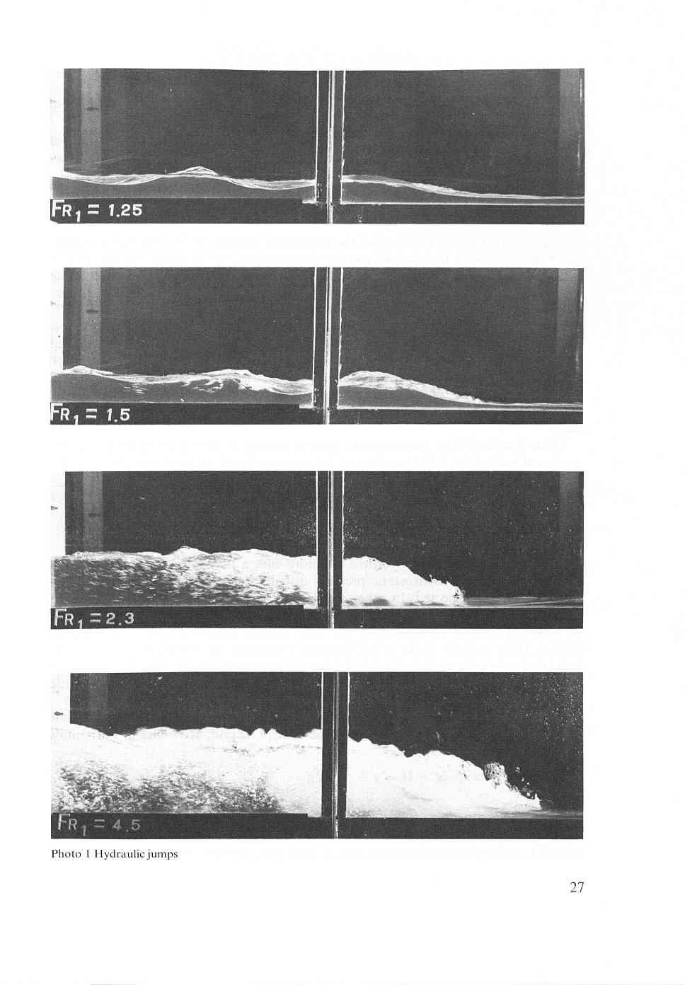
27
Basic equations of motion in fluid mechanics
 1 Annex 1 Basic equations of motion in fluid mechanics 1.1 Introduction It is assumed that the reader of this book is familiar with the basic laws of fluid mechanics. Nevertheless some of these laws will
Chapter 3 Bernoulli Equation
 1 Bernoulli Equation 3.1 Flow Patterns: Streamlines, Pathlines, Streaklines 1) A streamline, is a line that is everywhere tangent to the velocity vector at a given instant. Examples of streamlines around
NPTEL Quiz Hydraulics
 Introduction NPTEL Quiz Hydraulics 1. An ideal fluid is a. One which obeys Newton s law of viscosity b. Frictionless and incompressible c. Very viscous d. Frictionless and compressible 2. The unit of kinematic
5 Sharp-crested weirs
 5 Sharp-crested weirs Classified under the term sharp-crested or thin-plate weirs are those overflow structures whose length of crest in the direction of flow is equal to or less than two millimetres.
Long-Throated Flumes. 6. Hydraulic Theory and Computations for. 6.1 Continuity Equation
 6. Hydraulic Theory and Computations for Long-Throated Flumes The purpose of this chapter is to explain the fimdamental principles involved in analytically modeling the flow through weirs and flumes, so
The method by which this error has to be combined with other sources of error is I
 The error in the discharge coefficient (including C,) of a triangular broad-crested (truncated) eir, hich has been constructed ith reasonable care and skill, may be deduced form the equation X, = f (3
UNIT I FLUID PROPERTIES AND STATICS
 SIDDHARTH GROUP OF INSTITUTIONS :: PUTTUR Siddharth Nagar, Narayanavanam Road 517583 QUESTION BANK (DESCRIPTIVE) Subject with Code : Fluid Mechanics (16CE106) Year & Sem: II-B.Tech & I-Sem Course & Branch:
Open Channel Hydraulics III - Sharpcrested
 PDHonline Course H140 (2 PDH) Open Channel Hydraulics III - Sharpcrested Weirs Instructor: Harlan H. Bengtson, Ph.D., PE 2012 PDH Online PDH Center 5272 Meadow Estates Drive Fairfax, VA 22030-6658 Phone
If a stream of uniform velocity flows into a blunt body, the stream lines take a pattern similar to this: Streamlines around a blunt body
 Venturimeter & Orificemeter ELEMENTARY HYDRAULICS National Certificate in Technology (Civil Engineering) Chapter 5 Applications of the Bernoulli Equation The Bernoulli equation can be applied to a great
Chapter 4 DYNAMICS OF FLUID FLOW
 Faculty Of Engineering at Shobra nd Year Civil - 016 Chapter 4 DYNAMICS OF FLUID FLOW 4-1 Types of Energy 4- Euler s Equation 4-3 Bernoulli s Equation 4-4 Total Energy Line (TEL) and Hydraulic Grade Line
Discharge measurements
 Discharge measurements DISCHARGE MEASUREMENTS Suitability of methods and equipment for measurements where, under what conditions and for what reason discharge is measured determination of discharge in
2.The lines that are tangent to the velocity vectors throughout the flow field are called steady flow lines. True or False A. True B.
 CHAPTER 03 1. Write Newton's second law of motion. YOUR ANSWER: F = ma 2.The lines that are tangent to the velocity vectors throughout the flow field are called steady flow lines. True or False 3.Streamwise
Hydromechanics: Course Summary
 Hydromechanics: Course Summary Hydromechanics VVR090 Material Included; French: Chapters to 9 and 4 + Sample problems Vennard & Street: Chapters 8 + 3, and (part of it) Roberson & Crowe: Chapter Collection
R09. d water surface. Prove that the depth of pressure is equal to p +.
 Code No:A109210105 R09 SET-1 B.Tech II Year - I Semester Examinations, December 2011 FLUID MECHANICS (CIVIL ENGINEERING) Time: 3 hours Max. Marks: 75 Answer any five questions All questions carry equal
Comparative Analysis of a Parabolic Weir
 Comparative Analysis of a Parabolic Weir Prajakta N. Badhe 1, Mohd. Zain Kangda 2, Shobha G. Kundu 3, Abdul Ashfak Khan 4 Asst. Professor, Department of Civil Engineering, PCE, Maharashtra, India 1 Asst.
Chapter 4: Non uniform flow in open channels
 Chapter 4: Non uniform flow in open channels Learning outcomes By the end of this lesson, students should be able to: Relate the concept of specific energy and momentum equations in the effect of change
5 ENERGY EQUATION OF FLUID MOTION
 5 ENERGY EQUATION OF FLUID MOTION 5.1 Introduction In order to develop the equations that describe a flow, it is assumed that fluids are subject to certain fundamental laws of physics. The pertinent laws
Rate of Flow Quantity of fluid passing through any section (area) per unit time
 per unit time") Kinematics of Fluid Flow Kinematics is the science which deals with study of motion of liquids without considering the forces causing the motion. Rate of Flow Quantity of fluid passing through any section
Kinematics of Fluid Flow Kinematics is the science which deals with study of motion of liquids without considering the forces causing the motion. Rate of Flow Quantity of fluid passing through any section
For example an empty bucket weighs 2.0kg. After 7 seconds of collecting water the bucket weighs 8.0kg, then:
 Hydraulic Coefficient & Flow Measurements ELEMENTARY HYDRAULICS National Certificate in Technology (Civil Engineering) Chapter 3 1. Mass flow rate If we want to measure the rate at which water is flowing
The Bernoulli Equation
 The Bernoulli Equation The most used and the most abused equation in fluid mechanics. Newton s Second Law: F = ma In general, most real flows are 3-D, unsteady (x, y, z, t; r,θ, z, t; etc) Let consider
FLUID MECHANICS. Chapter 3 Elementary Fluid Dynamics - The Bernoulli Equation
 FLUID MECHANICS Chapter 3 Elementary Fluid Dynamics - The Bernoulli Equation CHAP 3. ELEMENTARY FLUID DYNAMICS - THE BERNOULLI EQUATION CONTENTS 3. Newton s Second Law 3. F = ma along a Streamline 3.3
Minimum Specific Energy and Critical Flow Conditions in Open Channels
 Minimum Specific Energy and Critical Flow Conditions in Open Channels by H. Chanson 1 Abstract : In open channels, the relationship between the specific energy and the flow depth exhibits a minimum, and
Lecture Note for Open Channel Hydraulics
 Chapter -one Introduction to Open Channel Hydraulics 1.1 Definitions Simply stated, Open channel flow is a flow of liquid in a conduit with free space. Open channel flow is particularly applied to understand
CEE 3310 Control Volume Analysis, Oct. 7, D Steady State Head Form of the Energy Equation P. P 2g + z h f + h p h s.
 CEE 3310 Control Volume Analysis, Oct. 7, 2015 81 3.21 Review 1-D Steady State Head Form of the Energy Equation ( ) ( ) 2g + z = 2g + z h f + h p h s out where h f is the friction head loss (which combines
53:071 Principles of Hydraulics Laboratory Experiment #3 ANALYSIS OF OPEN-CHANNEL FLOW TRANSITIONS USING THE SPECIFIC ENERGY DIAGRAM
 53:071 Principles of Hydraulics Laboratory Experiment #3 ANALYSIS OF OPEN-CHANNEL FLOW TRANSITIONS USING THE SPECIFIC ENERGY DIAGRAM Principle Adaptation of the Bernoulli equation to open-channel flows
EFFECT OF VERTICAL CURVATURE OF FLOW AT WEIR CREST ON DISCHARGE COEFFICIENT
 Ninth International Water Technology Conference, IWTC9 2005, Sharm El-Sheikh, Egypt 249 EFFECT OF VERTICAL CURVATURE OF FLOW AT WEIR CREST ON DISCHARGE COEFFICIENT Kassem Salah El-Alfy Associate Prof.,
University of Engineering and Technology, Taxila. Department of Civil Engineering
 University of Engineering and Technology, Taxila Department of Civil Engineering Course Title: CE-201 Fluid Mechanics - I Pre-requisite(s): None Credit Hours: 2 + 1 Contact Hours: 2 + 3 Text Book(s): Reference
Objectives. Conservation of mass principle: Mass Equation The Bernoulli equation Conservation of energy principle: Energy equation
 Objectives Conservation of mass principle: Mass Equation The Bernoulli equation Conservation of energy principle: Energy equation Conservation of Mass Conservation of Mass Mass, like energy, is a conserved
FLOW MEASUREMENT IN PIPES EXPERIMENT
 University of Leicester Engineering Department FLOW MEASUREMENT IN PIPES EXPERIMENT Page 1 FORMAL LABORATORY REPORT Name of the experiment: FLOW MEASUREMENT IN PIPES Author: Apollin nana chaazou Partner
Experimental Investigation on the Influence of Density of Fluid. On Efficiency of V- Notch
 International Journal of Advances in Scientific Research and Engineering (ijasre) E-ISSN : 2454-8006 DOI: http://dx.doi.org/10.7324/ijasre.2017.32515 Vol.3 (9) Oct - 2017 Experimental Investigation on
Discharge Measurements in Open Channels using Compound Sharp-Crested Weirs
 I'NCINEER - Vol. XXXX, No. 03, pp. 31-38,2007 O Tlie Institution of Engineers, Sri Lanka Discharge Measurements in Open Channels using Compound Sharp-Crested Weirs M. Piratheepan, N.E.F. Winston and K.P.P.
CHAPTER 3 BASIC EQUATIONS IN FLUID MECHANICS NOOR ALIZA AHMAD
 CHAPTER 3 BASIC EQUATIONS IN FLUID MECHANICS 1 INTRODUCTION Flow often referred as an ideal fluid. We presume that such a fluid has no viscosity. However, this is an idealized situation that does not exist.
INSTITUTE OF AERONAUTICAL ENGINEERING Dundigal, Hyderabad AERONAUTICAL ENGINEERING QUESTION BANK : AERONAUTICAL ENGINEERING.
 Course Name Course Code Class Branch INSTITUTE OF AERONAUTICAL ENGINEERING Dundigal, Hyderabad - 00 0 AERONAUTICAL ENGINEERING : Mechanics of Fluids : A00 : II-I- B. Tech Year : 0 0 Course Coordinator
S.E. (Mech.) (First Sem.) EXAMINATION, (Common to Mech/Sandwich) FLUID MECHANICS (2008 PATTERN) Time : Three Hours Maximum Marks : 100
 (First Sem.) EXAMINATION, (Common to Mech/Sandwich) FLUID MECHANICS (2008 PATTERN) Time : Three Hours Maximum Marks : 100") Total No. of Questions 12] [Total No. of Printed Pages 8 Seat No. [4262]-113 S.E. (Mech.) (First Sem.) EXAMINATION, 2012 (Common to Mech/Sandwich) FLUID MECHANICS (2008 PATTERN) Time : Three Hours Maximum
Total No. of Questions 12] [Total No. of Printed Pages 8 Seat No. [4262]-113 S.E. (Mech.) (First Sem.) EXAMINATION, 2012 (Common to Mech/Sandwich) FLUID MECHANICS (2008 PATTERN) Time : Three Hours Maximum
MAHATMA GANDHI MISSION S JAWAHARLAL NEHRU ENGINEERING COLLEGE, FLUID MECHANICS LABORATORY MANUAL
 MAHATMA GANDHI MISSION S JAWAHARLAL NEHRU ENGINEERING COLLEGE, AURANGABAD. (M.S.) DEPARTMENT OF CIVIL ENGINEERING FLUID MECHANICS LABORATORY MANUAL Prepared By Mr. L. K. Kokate Lab Incharge Approved By
Laboratory experiences on open channel flow (in collaboration with Dr. Ing. Luca Milanesi)
") Classwork 8 Laboratory experiences on open channel flow (in collaboration with Dr. Ing. Luca Milanesi) Why a practical lesson on open channel flow? In the first part of the course we studied open channel
Classwork 8 Laboratory experiences on open channel flow (in collaboration with Dr. Ing. Luca Milanesi) Why a practical lesson on open channel flow? In the first part of the course we studied open channel
10.52 Mechanics of Fluids Spring 2006 Problem Set 3
 10.52 Mechanics of Fluids Spring 2006 Problem Set 3 Problem 1 Mass transfer studies involving the transport of a solute from a gas to a liquid often involve the use of a laminar jet of liquid. The situation
Flow Characteristics and Modelling of Head-discharge Relationships for Weirs
 Chapter 8 Flow Characteristics and Modelling of Head-discharge Relationships for Weirs 8.1 Introduction In Chapters 5 and 7, the formulations of the numerical models for the simulations of flow surface
Chapter Four fluid flow mass, energy, Bernoulli and momentum
 4-1Conservation of Mass Principle Consider a control volume of arbitrary shape, as shown in Fig (4-1). Figure (4-1): the differential control volume and differential control volume (Total mass entering
Mass of fluid leaving per unit time
 5 ENERGY EQUATION OF FLUID MOTION 5.1 Eulerian Approach & Control Volume In order to develop the equations that describe a flow, it is assumed that fluids are subject to certain fundamental laws of physics.
6.4 Head-Discharge Equations Based on Experimentation
 ~ contracted, we have found that L = 0.25bC does not produce an accurate rating, but an accurate rating is obtained with L = 2b,. At the present time the WinFlume computer program will warn the designer
Lecture 10: River Channels
 GEOG415 Lecture 10: River Channels 10-1 Importance of channel characteristics Prediction of flow was the sole purpose of hydrology, and still is a very important aspect of hydrology. - Water balance gives
EFFECT OF BAFFLE BLOCKS ON THE PERFORMANCE OF RADIAL HYDRAULIC JUMP
 Fourth International Water Technology Conference IWTC 99, Alexandria, Egypt 255 EFFECT OF BAFFLE BLOCKS ON THE PERFORMANCE OF RADIAL HYDRAULIC JUMP O. S. Rageh Irrigation & Hydraulics Dept., Faculty of
Closed duct flows are full of fluid, have no free surface within, and are driven by a pressure gradient along the duct axis.
 OPEN CHANNEL FLOW Open channel flow is a flow of liquid, basically water in a conduit with a free surface. The open channel flows are driven by gravity alone, and the pressure gradient at the atmospheric
MAHATMA GANDHI MISSION S JAWAHARLAL NEHRU ENGINEERING COLLEGE, AURANGABAD. (M.S.)
") MAHATMA GANDHI MISSION S JAWAHARLAL NEHRU ENGINEERING COLLEGE, AURANGABAD. (M.S.) DEPARTMENT OF CIVIL ENGINEERING FLUID MECHANICS I LAB MANUAL Prepared By Prof. L. K. Kokate Lab Incharge Approved By Dr.
MAHATMA GANDHI MISSION S JAWAHARLAL NEHRU ENGINEERING COLLEGE, AURANGABAD. (M.S.) DEPARTMENT OF CIVIL ENGINEERING FLUID MECHANICS I LAB MANUAL Prepared By Prof. L. K. Kokate Lab Incharge Approved By Dr.
Fluid Mechanics. du dy
 FLUID MECHANICS Technical English - I 1 th week Fluid Mechanics FLUID STATICS FLUID DYNAMICS Fluid Statics or Hydrostatics is the study of fluids at rest. The main equation required for this is Newton's
presented by Umut Türker Open Channel Flow
 presented by Umut Türker Open Channel Flow What is open channel flow? Open channel flow is a flow which has a free surface and flows due to the gravitational effect What is open channel flow? Open channel
Head Discharge Relationship of Thin Plated Rectangular Lab Fabricated Sharp Crested Weirs
 Journal of Applied Fluid Mechanics, Vol. 9, No. 3, pp. 1231-1235, 2016. Available online at www.jafmonline.net, ISSN 1735-3572, EISSN 1735-3645. DOI: 10.18869/acadpub.jafm.68.228.23128 Head Discharge Relationship
Experiment- To determine the coefficient of impact for vanes. Experiment To determine the coefficient of discharge of an orifice meter.
 SUBJECT: FLUID MECHANICS VIVA QUESTIONS (M.E 4 th SEM) Experiment- To determine the coefficient of impact for vanes. Q1. Explain impulse momentum principal. Ans1. Momentum equation is based on Newton s
Lecture 24. Design of flow meters
 Lecture 24 Design of flow meters Contents Exercise 1 Exercise 2 Exercise 3 Key Words: Fluid flow, Macroscopic Balance, Frictional Losses, Turbulent Flow, Venturimeter, Orifice Meter, Pitot Tube Exercise
Cavitation occurs whenever the pressure in the flow of water drops to the value of the pressure of the saturated water vapour, pv (at the prevailing
 Cavitation occurs whenever the pressure in the flow of water drops to the value of the pressure of the saturated water vapour, pv (at the prevailing temperature); cavities filled by vapour, and partly
Stage Discharge Tabulation for Only Orifice Flow
 Stage Discharge Tabulation for Only Orifice Flow DEPTH STAGE DISCHARGE (meters) (feet) (meters) (feet) (m 3 /s) (ft 3 /s) 0 0.20 0.40 0.60 0.80 1.00 1.20 1.40 1.60 1.80 2.00 0.7 1.3 2.0 2.6 3.3 3.9 4.6
Experiment (4): Flow measurement
: Flow measurement") Experiment (4): Flow measurement Introduction: The flow measuring apparatus is used to familiarize the students with typical methods of flow measurement of an incompressible fluid and, at the same time
Experiment (4): Flow measurement Introduction: The flow measuring apparatus is used to familiarize the students with typical methods of flow measurement of an incompressible fluid and, at the same time
Fundamentals of Fluid Mechanics
 Sixth Edition Fundamentals of Fluid Mechanics International Student Version BRUCE R. MUNSON DONALD F. YOUNG Department of Aerospace Engineering and Engineering Mechanics THEODORE H. OKIISHI Department
Application of an ultrasonic velocity profile monitor in a hydraulic laboratory
 Application of an ultrasonic velocity profile monitor in a hydraulic laboratory Abstract Helmut Knoblauch 1, Roman Klasinc 1, Thomas Geisler 1 Velocity profile measurement using the ultrasound-pulse-doppler
Stream Tube. When density do not depend explicitly on time then from continuity equation, we have V 2 V 1. δa 2. δa 1 PH6L24 1
 Stream Tube A region of the moving fluid bounded on the all sides by streamlines is called a tube of flow or stream tube. As streamline does not intersect each other, no fluid enters or leaves across the
9. Flood Routing. chapter Two
 9. Flood Routing Flow routing is a mathematical procedure for predicting the changing magnitude, speed, and shape of a flood wave as a function of time at one or more points along a watercourse (waterway
CEE 3310 Control Volume Analysis, Oct. 10, = dt. sys
 CEE 3310 Control Volume Analysis, Oct. 10, 2018 77 3.16 Review First Law of Thermodynamics ( ) de = dt Q Ẇ sys Sign convention: Work done by the surroundings on the system < 0, example, a pump! Work done
Visualization of flow pattern over or around immersed objects in open channel flow.
 EXPERIMENT SEVEN: FLOW VISUALIZATION AND ANALYSIS I OBJECTIVE OF THE EXPERIMENT: Visualization of flow pattern over or around immersed objects in open channel flow. II THEORY AND EQUATION: Open channel:
SOE2156: Fluids Lecture 7
 Weirs and SOE2156: Fluids Lecture 7 Vee Vee Last lecture { assumed the channel was uniform (constant depth, shape, slope etc.) { steady uniform Found that : location of free surface to be determined 2
Chapter 6 The Impulse-Momentum Principle
 Chapter 6 The Impulse-Momentum Principle 6. The Linear Impulse-Momentum Equation 6. Pipe Flow Applications 6.3 Open Channel Flow Applications 6.4 The Angular Impulse-Momentum Principle Objectives: - Develop
DEPARTMENT OF CIVIL AND ENVIRONMENTAL ENGINEERING Urban Drainage: Hydraulics. Solutions to problem sheet 2: Flows in open channels
 DEPRTMENT OF CIVIL ND ENVIRONMENTL ENGINEERING Urban Drainage: Hydraulics Solutions to problem sheet 2: Flows in open channels 1. rectangular channel of 1 m width carries water at a rate 0.1 m 3 /s. Plot
Fluid Mechanics Prof. S.K. Som Department of Mechanical Engineering Indian Institute of Technology, Kharagpur
 Fluid Mechanics Prof. S.K. Som Department of Mechanical Engineering Indian Institute of Technology, Kharagpur Lecture - 42 Flows with a Free Surface Part II Good morning. I welcome you to this session
Laboratory exercise 1: Open channel flow measurement
 Chapter 1 Laboratory exercise 1: Open channel flow measurement Laboratory exercise Open channel flow measurement is placed on the Faculty of Civil and Geodetic Engineering, on Department of Environmental
y 2 = 1 + y 1 This is known as the broad-crested weir which is characterized by:
 CEE 10 Open Channel Flow, Dec. 1, 010 18 8.16 Review Flow through a contraction Critical and choked flows The hydraulic jump conservation of linear momentum y = 1 + y 1 1 + 8Fr 1 8.17 Rapidly Varied Flows
UNIT IV. Flow through Orifice and Mouthpieces and Flow through Notchs and Weirs
 SIDDHARTH GROUP OF INSTITUTIONS :: PUTTUR Siddharth Nagar, Narayanavanam Road 517583 QUESTION BANK (DESCRIPTIVE) Subject with Code : FM(15A01305) Year & Sem: II-B.Tech & I-Sem Course & Branch: B.Tech -
CIE4491 Lecture. Hydraulic design
 CIE4491 Lecture. Hydraulic design Marie-claire ten Veldhuis 19-9-013 Delft University of Technology Challenge the future Hydraulic design of urban stormwater systems Focus on sewer pipes Pressurized and
Lecture 3 The energy equation
 Lecture 3 The energy equation Dr Tim Gough: t.gough@bradford.ac.uk General information Lab groups now assigned Timetable up to week 6 published Is there anyone not yet on the list? Week 3 Week 4 Week 5
VARIED FLOW IN OPEN CHANNELS
 Chapter 15 Open Channels vs. Closed Conduits VARIED FLOW IN OPEN CHANNELS Fluid Mechanics, Spring Term 2011 In a closed conduit there can be a pressure gradient that drives the flow. An open channel has
Experimental Investigations of Nappe Profile and Pool Depth for Broad Crested Weirs
 International Journal of Engineering Research and General Science Volume, Issue, January-February, ISSN 9-73 Experimental Investigations of Nappe Profile and Pool Depth for Broad Crested Weirs Mohammed
BRCM COLLEGE OF ENGINEERING & TECHNOLOGY Practical Experiment Instructions Sheet
 Exp. Title FLUID MECHANICS- I LAB Syllabus FM-I Semester-4 th Page No. 1 of 1 Internal Marks: 25 L T P External Marks: 25 0 0 2 Total Marks: 50 1. To determine the met centric height of a floating body
Lecture23. Flowmeter Design.
 Lecture23 Flowmeter Design. Contents of lecture Design of flowmeter Principles of flow measurement; i) Venturi and ii) Orifice meter and nozzle Relationship between flow rate and pressure drop Relation
The Impulse-Momentum Principle
 Chapter 6 /60 The Impulse-Momentum Principle F F Chapter 6 The Impulse-Momentum Principle /60 Contents 6.0 Introduction 6. The Linear Impulse-Momentum Equation 6. Pipe Flow Applications 6.3 Open Channel
conservation of linear momentum 1+8Fr = 1+ Sufficiently short that energy loss due to channel friction is negligible h L = 0 Bernoulli s equation.
 174 Review Flow through a contraction Critical and choked flows The hydraulic jump conservation of linear momentum y y 1 = 1+ 1+8Fr 1 8.1 Rapidly Varied Flows Weirs 8.1.1 Broad-Crested Weir Consider the
Rock Sizing for Waterway & Gully Chutes
 Rock Sizing for Waterway & Gully Chutes WATERWAY MANAGEMENT PRACTICES Photo 1 Rock-lined waterway chute Photo 2 Rock-lined gully chute 1. Introduction A waterway chute is a stabilised section of channel
Physics 123 Unit #1 Review
 Physics 123 Unit #1 Review I. Definitions & Facts Density Specific gravity (= material / water) Pressure Atmosphere, bar, Pascal Barometer Streamline, laminar flow Turbulence Gauge pressure II. Mathematics
Closed duct flows are full of fluid, have no free surface within, and are driven by a pressure gradient along the duct axis.
 OPEN CHANNEL FLOW Open channel flow is a flow of liquid, basically water in a conduit with a free surface. The open channel flows are driven by gravity alone, and the pressure gradient at the atmospheric
Annex 3 Side weirs and oblique weirs
 Annex 3 Side weirs and oblique weirs 3.1 ntroduction Most of the weirs described in this book serve mainly to measure discharges. Some, however, such as those described in Chapters 4 and 6 can also be
V/ t = 0 p/ t = 0 ρ/ t = 0. V/ s = 0 p/ s = 0 ρ/ s = 0
 UNIT III FLOW THROUGH PIPES 1. List the types of fluid flow. Steady and unsteady flow Uniform and non-uniform flow Laminar and Turbulent flow Compressible and incompressible flow Rotational and ir-rotational
10 minutes reading time is allowed for this paper.
 EGT1 ENGINEERING TRIPOS PART IB Tuesday 31 May 2016 2 to 4 Paper 4 THERMOFLUID MECHANICS Answer not more than four questions. Answer not more than two questions from each section. All questions carry the
OPEN CHANNEL FLOW. One-dimensional - neglect vertical and lateral variations in velocity. In other words, Q v = (1) A. Figure 1. One-dimensional Flow
 A. Figure 1. One-dimensional Flow") OPEN CHANNEL FLOW Page 1 OPEN CHANNEL FLOW Open Channel Flow (OCF) is flow with one boundary exposed to atmospheric pressure. The flow is not pressurized and occurs because of gravity. Flow Classification
OPEN CHANNEL FLOW Page 1 OPEN CHANNEL FLOW Open Channel Flow (OCF) is flow with one boundary exposed to atmospheric pressure. The flow is not pressurized and occurs because of gravity. Flow Classification
Stream flow measurements are fundamental in water management and. Different streams and rivers require
 Stream Flow Measurements Introduction Stream flow measurements are fundamental in water management and projects Different streams and rivers require appropriate flow measurement methods Weirs and Flumes
Lesson 6 Review of fundamentals: Fluid flow
 Lesson 6 Review of fundamentals: Fluid flow The specific objective of this lesson is to conduct a brief review of the fundamentals of fluid flow and present: A general equation for conservation of mass
ENGINEERING FLUID MECHANICS. CHAPTER 1 Properties of Fluids
 CHAPTER 1 Properties of Fluids ENGINEERING FLUID MECHANICS 1.1 Introduction 1.2 Development of Fluid Mechanics 1.3 Units of Measurement (SI units) 1.4 Mass, Density, Specific Weight, Specific Volume, Specific
Physics 3 Summer 1990 Lab 7 - Hydrodynamics
 Physics 3 Summer 1990 Lab 7 - Hydrodynamics Theory Consider an ideal liquid, one which is incompressible and which has no internal friction, flowing through pipe of varying cross section as shown in figure
Chapter 7 The Energy Equation
 Chapter 7 The Energy Equation 7.1 Energy, Work, and Power When matter has energy, the matter can be used to do work. A fluid can have several forms of energy. For example a fluid jet has kinetic energy,
ME332 FLUID MECHANICS LABORATORY (PART I)
") ME332 FLUID MECHANICS LABORATORY (PART I) Mihir Sen Department of Aerospace and Mechanical Engineering University of Notre Dame Notre Dame, IN 46556 Version: January 14, 2002 Contents Unit 1: Hydrostatics
ME332 FLUID MECHANICS LABORATORY (PART I) Mihir Sen Department of Aerospace and Mechanical Engineering University of Notre Dame Notre Dame, IN 46556 Version: January 14, 2002 Contents Unit 1: Hydrostatics
3.25 Pressure form of Bernoulli Equation
 CEE 3310 Control Volume Analysis, Oct 3, 2012 83 3.24 Review The Energy Equation Q Ẇshaft = d dt CV ) (û + v2 2 + gz ρ d + (û + v2 CS 2 + gz + ) ρ( v n) da ρ where Q is the heat energy transfer rate, Ẇ
Fluid Mechanics Testbank By David Admiraal
 Fluid Mechanics Testbank By David Admiraal This testbank was created for an introductory fluid mechanics class. The primary intentions of the testbank are to help students improve their performance on
DIVIDED SYLLABUS ( ) - CLASS XI PHYSICS (CODE 042) COURSE STRUCTURE APRIL
 - CLASS XI PHYSICS (CODE 042) COURSE STRUCTURE APRIL") DIVIDED SYLLABUS (2015-16 ) - CLASS XI PHYSICS (CODE 042) COURSE STRUCTURE APRIL Unit I: Physical World and Measurement Physics Need for measurement: Units of measurement; systems of units; SI units, fundamental
DIVIDED SYLLABUS (2015-16 ) - CLASS XI PHYSICS (CODE 042) COURSE STRUCTURE APRIL Unit I: Physical World and Measurement Physics Need for measurement: Units of measurement; systems of units; SI units, fundamental
PHYSICS 221 SPRING EXAM 1: February 20, 2014; 8:15pm 10:15pm
 PHYSICS 221 SPRING 2014 EXAM 1: February 20, 2014; 8:15pm 10:15pm Name (printed): Recitation Instructor: Section # INSTRUCTIONS: This exam contains 25 multiple-choice questions plus 2 extra credit questions,
Approximate physical properties of selected fluids All properties are given at pressure kn/m 2 and temperature 15 C.
 Appendix FLUID MECHANICS Approximate physical properties of selected fluids All properties are given at pressure 101. kn/m and temperature 15 C. Liquids Density (kg/m ) Dynamic viscosity (N s/m ) Surface
Lecture 13 Flow Measurement in Pipes. I. Introduction
 Lecture 13 Flow Measurement in Pipes I. Introduction There are a wide variety of methods for measuring discharge and velocity in pipes, or closed conduits Many of these methods can provide very accurate
Fluid Mechanics Lab (ME-216-F) List of Experiments
 List of Experiments") Fluid Mechanics Lab (ME-216-F) List of Experiments 1. To determine the coefficient of discharge C d, velocity C v, and contraction C c of various types of orifices 2. Determine of discharge coefficients
Fluid Mechanics Lab (ME-216-F) List of Experiments 1. To determine the coefficient of discharge C d, velocity C v, and contraction C c of various types of orifices 2. Determine of discharge coefficients
Reservoir Oscillations with Through Flow
 American Journal of Environmental Sciences 3 (): 37-42, 27 ISSN 553-345X 27 Science Publications Reservoir Oscillations with Through Flow A. A. Khan 28 Lowry Hall, epartment of Civil Engineering, Clemson
Development of Discharge Prediction Model for Trapezoidal Canals using Simple Portable Flume
 International Journal of Hydraulic Engineering 01, 1(5): 37-4 OI: 10.593/j.ijhe.010105.0 evelopment of ischarge Prediction Model for Trapezoidal Canals using Simple Portable Flume Avinash M. Badar, Aniruddha.
EXPERIMENT No.1 FLOW MEASUREMENT BY ORIFICEMETER
 EXPERIMENT No.1 FLOW MEASUREMENT BY ORIFICEMETER 1.1 AIM: To determine the co-efficient of discharge of the orifice meter 1.2 EQUIPMENTS REQUIRED: Orifice meter test rig, Stopwatch 1.3 PREPARATION 1.3.1
1.060 Engineering Mechanics II Spring Problem Set 8
 1.060 Engineering Mechanics II Spring 2006 Due on Monday, May 1st Problem Set 8 Important note: Please start a new sheet of paper for each problem in the problem set. Write the names of the group members
1. A sphere with a radius of 1.7 cm has a volume of: A) m 3 B) m 3 C) m 3 D) 0.11 m 3 E) 21 m 3
 m 3 B) m 3 C) m 3 D) 0.11 m 3 E) 21 m 3") 1. A sphere with a radius of 1.7 cm has a volume of: A) 2.1 10 5 m 3 B) 9.1 10 4 m 3 C) 3.6 10 3 m 3 D) 0.11 m 3 E) 21 m 3 2. A 25-N crate slides down a frictionless incline that is 25 above the horizontal.
1. A sphere with a radius of 1.7 cm has a volume of: A) 2.1 10 5 m 3 B) 9.1 10 4 m 3 C) 3.6 10 3 m 3 D) 0.11 m 3 E) 21 m 3 2. A 25-N crate slides down a frictionless incline that is 25 above the horizontal.
28.2 Classification of Jumps
 28.2 Classification of Jumps As mentioned earlier, the supercritical flow Froude number influences the characteristics of the hydraulic jump. Bradley and Peterka, after extensive experimental investigations,