CMPE12 - Notes chapter 2. Digital Logic. (Textbook Chapters and 2.1)"
|
|
|
- Alaina Bond
- 6 years ago
- Views:
Transcription
1 CMPE12 - Notes chapter 2 Digital Logic (Textbook Chapters and 2.1)"
2 Truth table" The most basic representation of a logic function." Brute force representation listing the output for all possible input combinations." CMPE12 Fall 2011 J. Ferguson" 2-2"
3 Truth table example" Input" Output" A B" A or B" F F" F" F T" T" T F" T" T T" T" 2 #inputs F -> 0 T -> 1 Input" Output" A B" A+B" 0 0" 0" 0 1" 1" 1 0" 1" 1 1" 1" CMPE12 Fall 2011 J. Ferguson" 2-3"
4 More truth tables" Input" Output" Input" Output" A B" A and B" A B" A nand B" 0 0" 0" 0 0" 1" 0 1" 0" 0 1" 1" 1 0" 0" 1 0" 1" 1 1" 1" 1 1" 0" Input Outputs Input" Output" A B X Y A" not A" 0 " 1" 1" 0" CMPE12 Fall 2011 J. Ferguson" 2-4"
5 Basic logic gates" CMPE12 Fall 2011 J. Ferguson" 2-5"
6 Transistor: Building Block of Computers (and logic gates)" Microprocessors contain LOTS of transistors! Intel Montecito (2005): 1.72 billion" Intel Pentium 4 (2000): 48 million" IBM PowerPC 750FX (2002): 38 million" IBM/Apple PowerPC G5 (2003): 58 million" Intel 4004 (1971): 2500" CMPE12 Fall 2011 J. Ferguson" 2-6"


7 Mooreʼs Law" The number of active components per chip will double every 18 months " CMPE12 Fall 2011 J. Ferguson" 2-7"
8 New architectures grow even faster!" CMPE12 Fall 2011 J. Ferguson" 2-8"
9 Transistors = switches" Logically, each transistor is used as a switch" Combined to implement logic functions " AND, OR, NOT" Combined to build higher-level structures" Adder, multiplexer, decoder, register, " Combined to build processor" LC-3" CMPE12 Fall 2011 J. Ferguson" 2-9"
10 Metal-Oxide-Semiconductor (MOS) transistor" CMPE12 Fall 2011 J. Ferguson" 2-10"

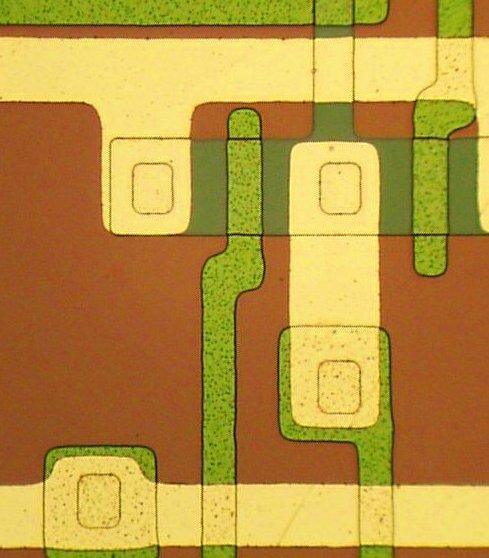
11 Metal-Oxide-Semiconductor (MOS) transistor" CMPE12 Fall 2011 J. Ferguson" 2-11"
12 Transistor opens and closes path for electricity" CMPE12 Fall 2011 J. Ferguson" 2-12"
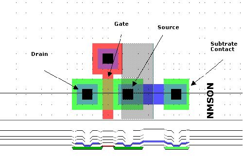
13 n-type MOS transistor" n-type MOS (nmos)! when Gate has positive voltage, short circuit between #1 and #2 (switch closed)" when Gate has zero voltage, open circuit between #1 and #2 (switch open)" Gate = 1 Terminal #2 must be connected to GND (0V). Gate = 0 CMPE12 Fall 2011 J. Ferguson" 2-13"
14 p-type MOS transistor" p-type is complementary to n-type" when Gate has positive voltage, open circuit between #1 and #2 (switch open)" when Gate has zero voltage, short circuit between #1 and #2 (switch closed)" Gate = 1 Terminal #1 must be connected to +2.9V in this example. Gate = 0 CMPE12 Fall 2011 J. Ferguson" 2-14"
15 Logic gates" Use switch behavior of MOS transistors to implement logical functions: AND, OR, NOT." Digital symbols:" recall that we assign a range of analog voltages to each digital (logic) symbol" assignment of voltage ranges depends on electrical properties of transistors being used" typical values for "1": +5V, +3.3V, +2.9V. +1.8V, +1.2V, 1 V" from now on we'll use 1 volt" CMPE12 Fall 2011 J. Ferguson" 2-15"
16 CMOS circuit" Complementary MOS" Uses both n-type and p-type MOS transistors" p-type" Attached to + voltage" Pulls output voltage UP when input is zero" n-type" Attached to GND" Pulls output voltage DOWN when input is one! CMPE12 Fall 2011 J. Ferguson" 2-16"
17 Inverter (NOT gate)" 1 volt 0 volts In Out In Out 0 V 1 V V 0 V 1 0 Truth Table CMPE12 Fall 2011 J. Ferguson" 2-17"
18 CMOS vs. TTL inverter" CMOS (modern)! TTL (1960ʼs 80ʼs)! CMPE12 Fall 2011 J. Ferguson" 2-18"
19 NAND gate (NOT-AND)" Note: Parallel structure on top, serial on bottom. A" B" C" 0" 0" 1" 0" 1" 1" 1" 0" 1" 1" 1" 0" CMPE12 Fall 2011 J. Ferguson" 2-19"
20 AND gate (nand-not)" A" B" C" Add an inverter to a NAND. (All Primitive Gates are inverting!) CMPE12 Fall 2011 J. Ferguson" 2-20"
21 Primitive AND gate - NO!" A B C A" B C What is wrong with this picture? CMPE12 Fall 2011 J. Ferguson" 2-21"
22 NOR gate" Note: Serial structure on top, parallel on bottom. A B CMPE12 Fall 2011 J. Ferguson" 2-22" C
23 OR gate" A B C Add an inverter to a NOR gate. CMPE12 Fall 2011 J. Ferguson" 2-23"
24 More than 2 inputs?" AND/OR can take any number of inputs." AND = 1 if all inputs are 1." OR = 1 if any input is 1." Similar for NAND/NOR" Can implement with multiple two-input gates, or with single CMOS circuit if NAND or NOR." CMPE12 Fall 2011 J. Ferguson" 2-24"
25 Sum of products" Standard way of synthesizing simple circuits. Ex:" A B Z CMPE12 Fall 2011 J. Ferguson" 2-25"
26 Building functions from logic gates" Combinational Logic Circuit! output depends only on the current inputs" Stateless" (what we are talking about now)" Sequential Logic Circuit! output depends on the sequence of inputs (past and present)" stores information (state) from past inputs" (we will talk about this later)" CMPE12 Fall 2011 J. Ferguson" 2-26"
27 What is the most confusing subject so far?" A. Chapter 1" B. Truth Tables / Sum of Products" C. FETs to build CMOS gate" D. Everything is easy (yawn!)" E. Nothing makes sense." CMPE12 Fall 2011 J. Ferguson" 2-27"
28 Multiplexer" 2-way multiplexer: the output is equal to one of the two inputs, based on a selector" S A B Z What is the formula for the MUX? Z =? Z = SʼABʼ + SʼAB + SAʼB + SAB! Z = SʼA + SB! CMPE12 Fall 2011 J. Ferguson" 2-28"
29 About the little circle" For both inputs and outputs" The little circle represents an inverter." " " "-or-" The little circle changes the meaning of what a logic 1 (0) is." CMPE12 Fall 2011 J. Ferguson" 2-29"
30 4-way multiplexer" n-bit selector and 2 n inputs, one output" output equals one of the inputs, depending on S inputs" to-1 MUX CMPE12 Fall 2011 J. Ferguson" 2-30"
31 More about FETs (Field Effect Transistors)" SoP formula for MUX: sa +s B = 12 transistors if Nand/Nand Need only 2 transistors with pass-transistor logic, but must have immediate restoring gate. CMPE12 Fall 2011 J. Ferguson" 2-31"
32 n inputs, 2 n outputs" Decoder" exactly one output is 1 for each possible input pattern" 2-to-4 decoder CMPE12 Fall 2011 J. Ferguson" 2-32"
33 Student T-shirt" There are 10 kinds of people: those that understand binary, and those that don t. CMPE12 Fall 2011 J. Ferguson" 2-33"
34 How to represent numbers: Unary, or marks:" Number Systems" " "/////// = 7" " "/////// + ////// = /////////////" Grouping lead to Roman Numerals:" " "VII + V = VVII = XII" Better: Arabic Numerals:" " "7 + 5 = 12 = 1 x " CMPE12 Fall 2011 J. Ferguson" 2-34"
35 Positional Number System" The value represented by a digit depends on its position in the number." Ex: 1832 = 1* * * *10 0 " CMPE12 Fall 2011 J. Ferguson" 2-35"
36 Positional Number System" Select a number as the base, b, ex:" Define an alphabet of b-1 symbols plus a symbol for zero to represent all numbers " Use an ordered sequence of digits to represent numbers " The represented number is the sum of all digits, each multiplied by b to the power of the digitʼs position p! Positional number systems are great for arithmetic" 1832 = 1* * * *10 0 " CMPE12 Fall 2011 J. Ferguson" 2-36"
37 Base two numbers" 101 b is 1*b 2 + 0*b 1 + 1*b 0" is 1* * *10 0" is 1* * *2 0 =?" 10 2 is 1* *2 0 =?" CMPE12 Fall 2011 J. Ferguson" 2-37"
38 Binary addition" = 0" = 1" = 1" = 0 with a carry of 1*2 1 " CMPE12 Fall 2011 J. Ferguson" 2-38"
\" C out (D)\" 0\" 0\" 0\" 0\" 0\" 1\" 1\" 0\" 1\" 0\" 1\" 0\" 1\" 1\" 0\" 1\" CMPE12")
39 Half Adder" Add two bits, produce one-bit sum and carry-out." A" B" S (C)" C out (D)" 0" 0" 0" 0" 0" 1" 1" 0" 1" 0" 1" 0" 1" 1" 0" 1" CMPE12 Fall 2011 J. Ferguson" 2-39"
40 Full Adder" Add two bits and carry-in, produce one-bit sum and carry-out." A" B" C in" S" C out" 0" 0" 0" 0" 0" 0" 0" 1" 1" 0" 0" 1" 0" 1" 0" 0" 1" 1" 0" 1" 1" 0" 0" 1" 0" 1" 0" 1" 0" 1" 1" 1" 0" 0" 1" 1" 1" 1" 1" 1" CMPE12 Fall 2011 J. Ferguson" 2-40"
41 Four-bit Adder" A 3 A 2 A 1 A 0 B 3 B 2 B 1 B 0 C out S 3 S 2 S 1 S 0 CMPE12 Fall 2011 J. Ferguson" 2-41"
42 Logical completeness" Can implement ANY truth table with AND, OR, NOT." A" B" C" D" 0! 0! 0! 0! 0! 0! 1! 0! 0! 1! 0! 1! 0! 1! 1! 0! 1! 0! 0! 0! 1! 0! 1! 1! 1! 1! 0! 0! 1! 1! 1! 0! 1. AND combinations that yield a "1" in the truth table." 2. OR the results of the AND gates." CMPE12 Fall 2011 J. Ferguson" 2-42"
43 Formalisms in Boolean Algebra" Warning! Math ahead. CMPE12 Fall 2011 J. Ferguson" 2-43"
44 Axioms of Boolean algebra" a. 0 * 0 = 0" b = 1 " c. 1 * 1 = 1" d = 0" e. 0 * 1 = 1 * 0 = 0" f = = 1" g. if x = 0 then xʼ = 1" h. if x = 1 then xʼ = 0" CMPE12 Fall 2011 J. Ferguson" 2-44"
45 Single-variable theorems" x * 0 =" x + 1 = " x * 1 =" x + 0 =" x * x =" x + x =" x * xʼ =" x + xʼ = " (xʼ)ʼ = " CMPE12 Fall 2011 J. Ferguson" 2-45"
46 Commutative: " x * y = y * x" x + y = y + x" Associative" x * (y * z) = (x * y) * z" x + (y + z) = (x + y) + z" Distributive" Properties "" x * (y + z ) = (x * y) + (x * z) = (x * y) + (x * z)" x + (y * z) = (x + y) * (x + z)" CMPE12 Fall 2011 J. Ferguson" 2-46"
47 More properties" Absorption:" x + x y = x" x(x + y) = x" Combining" x y + x yʼ = x" (x + y) (x + yʼ) = x" De Morganʼs" (x y)ʼ = xʼ + yʼ" (x + y)ʼ = xʼ yʼ" Other: x + (x y) = x + y x (x + y) = x y CMPE12 Fall 2011 J. Ferguson" 2-47"
48 Example:" Logic minimization" A B C Y Y = AʼBCʼ+AʼBC+ABʼCʼ+ABCʼ! = AʼB + ACʼ! combining! CMPE12 Fall 2011 J. Ferguson" 2-48"
49 DeMorgan's Law" (A + B)ʼ = AʼBʼ conversely (AB)ʼ = Aʼ + Bʼ! A B AB (AB) A B A +B CMPE12 Fall 2011 J. Ferguson" 2-49"
50 DeMorganʼs Law and logic gates" (A + B)ʼ = AʼBʼ! A+B = (AʼBʼ)ʼ! (JK + LM)ʼ = (JK)ʼ (LM)ʼ! JK + LM = ( (JK)ʼ (LM)ʼ )ʼ J K L M J K L M Same Function! CMPE12 Fall 2011 J. Ferguson" 2-50"
51 DeMorganʼs Law: And-Or Nand-Nand" J K J K L M L M SoP And/Or Nand/Nand" CMPE12 Fall 2011 J. Ferguson" 2-51"
52 DeMorganʼs Law: Or-And Nor-Nor" J K J K L M L M CMPE12 Fall 2011 J. Ferguson" 2-52"
53 Homework and Recommended exercises on combinational circuits (ignore for this class) Finish reading thru Chapter 3.5 and 2.1" Ex 3.5, 3.6, 3.7, 3.8, 3.9" Ex 3.11, 3.18" Ex 3.20 gate level circuit only, 3.22 ignore truth table, 3.23, 3.24a" Ex 3.30a,b; Ex 3.44" CMPE12 Fall 2011 J. Ferguson" 2-53"
54 Combinational vs. Sequential" Combinational circuit" always gives the same output for a given set of inputs" ex: adder always generates sum and carry, regardless of previous inputs" CMPE12 Fall 2011 J. Ferguson" 2-54"
55 Sequential circuit" stores information" output depends on stored information (state) plus input" so a given input might produce different outputs, depending on the stored information" example: ticket counter" advances when you push the button" output depends on previous state" useful for building memory elements and state machines " CMPE12 Fall 2011 J. Ferguson" 2-55"
56 Building Memory Units: Latches Flip-Flops Registers Memories, etc. CMPE12 Fall 2011 J. Ferguson" 2-56"
57 Set-Reset Latch" Two inputs: Set and Reset" Start with both inputs at 1 (memory)" Set to 0 one of the two inputs at a time to store a value" The transition 00 -> 11 generates an undefined output" NAND" A" B" C" 0" 0" 1" 0" 1" 1" 1" 0" 1" 1" 1" 0" CMPE12 Fall 2011 J. Ferguson" 2-57"
58 Gated SR-Latch = D-Latch" Two inputs: D (data) and WE (write enable)" when WE = 0, latch holds previous/current value" Sʼ = Rʼ = 1" when WE = 1, latch is set to value of D" S = NOT(D), R = D" CMPE12 Fall 2011 J. Ferguson" 2-58"
59 WE D Q time time time CMPE12 Fall 2011 J. Ferguson" 2-59"
60 D-Latch: Timing" It is possible to change the state only when the WE line is active. Sometimes called level-sensitive latch. D WE D Q E Q WE 1 0 time D 1 0 time Q 1 0 time CMPE12 Fall 2011 J. Ferguson" 2-60"
61 Register" A register stores a multi-bit value." We use a collection of D-latches, all controlled by a common WE." When WE=1, n-bit value D is written to register." CMPE12 Fall 2011 J. Ferguson" 2-61"
62 Memory" Now that we know how to store bits, we can build a memory a logical k m array of stored bits." Address Space: number of locations (usually a power of 2) Addressability: number of bits per location (e.g., byte-addressable) k = 2 n locations m bits CMPE12 Fall 2011 J. Ferguson" 2-62"
63 State Machines" CMPE12 Fall 2011 J. Ferguson" 2-63"

64 State Machine" The basic type of sequential circuit" Combines combinational logic with storage" Remembers state, and changes output (and state) based on inputs and current state" State Machine Inputs Combinational Logic Circuit Outputs Storage Elements CMPE12 Fall 2011 J. Ferguson" 2-64"
65 Combinational vs. Sequential" Two types of combination locks" Combinational Success depends only on the values, not the order in which they are set. Sequential Success depends on the sequence of values (e.g, R-13, L-22, R-3). CMPE12 Fall 2011 J. Ferguson" 2-65"
66 Two D-latches = One D Flip-Flop" Use a clock signal and connect it to the WE latch input. " Connect one latch to the inverted clock" CMPE12 Fall 2011 J. Ferguson" 2-66"
67 D-Flip Flop: Timing diagram" Ck 1 0 time D WE Ck D Q E Q WE 1 0 time D 1 0 time Q 1 0 time Edge-triggered flip-flop CMPE12 Fall 2011 J. Ferguson" 2-67"
68 Probable Recommended exercises What can you tell me about the values of A and B if S and R are both 1for Figure 3.18 in your text?" When are S and R both 1 in Figure 3.19 and what function is the circuit providing with this input?" Next: read chapter 4 CMPE12 Fall 2011 J. Ferguson" 2-68"
CMPE12 - Notes chapter 1. Digital Logic. (Textbook Chapter 3)
") CMPE12 - Notes chapter 1 Digital Logic (Textbook Chapter 3) Transistor: Building Block of Computers Microprocessors contain TONS of transistors Intel Montecito (2005): 1.72 billion Intel Pentium 4 (2000):
CMPE12 - Notes chapter 1 Digital Logic (Textbook Chapter 3) Transistor: Building Block of Computers Microprocessors contain TONS of transistors Intel Montecito (2005): 1.72 billion Intel Pentium 4 (2000):
Digital Logic: Boolean Algebra and Gates. Textbook Chapter 3
 Digital Logic: Boolean Algebra and Gates Textbook Chapter 3 Basic Logic Gates XOR CMPE12 Summer 2009 02-2 Truth Table The most basic representation of a logic function Lists the output for all possible
Introduction to Computer Engineering. CS/ECE 252, Fall 2012 Prof. Guri Sohi Computer Sciences Department University of Wisconsin Madison
 Introduction to Computer Engineering CS/ECE 252, Fall 2012 Prof. Guri Sohi Computer Sciences Department University of Wisconsin Madison Chapter 3 Digital Logic Structures Slides based on set prepared by
Digital Logic. CS211 Computer Architecture. l Topics. l Transistors (Design & Types) l Logic Gates. l Combinational Circuits.
 l Logic Gates. l Combinational Circuits.") CS211 Computer Architecture Digital Logic l Topics l Transistors (Design & Types) l Logic Gates l Combinational Circuits l K-Maps Figures & Tables borrowed from:! http://www.allaboutcircuits.com/vol_4/index.html!
CS211 Computer Architecture Digital Logic l Topics l Transistors (Design & Types) l Logic Gates l Combinational Circuits l K-Maps Figures & Tables borrowed from:! http://www.allaboutcircuits.com/vol_4/index.html!
Introduction to Computer Engineering. CS/ECE 252, Spring 2017 Rahul Nayar Computer Sciences Department University of Wisconsin Madison
 Introduction to Computer Engineering CS/ECE 252, Spring 2017 Rahul Nayar Computer Sciences Department University of Wisconsin Madison Chapter 3 Digital Logic Structures Slides based on set prepared by
Lecture 22 Chapters 3 Logic Circuits Part 1
 Lecture 22 Chapters 3 Logic Circuits Part 1 LC-3 Data Path Revisited How are the components Seen here implemented? 5-2 Computing Layers Problems Algorithms Language Instruction Set Architecture Microarchitecture
Boolean Algebra and Digital Logic 2009, University of Colombo School of Computing
 IT 204 Section 3.0 Boolean Algebra and Digital Logic Boolean Algebra 2 Logic Equations to Truth Tables X = A. B + A. B + AB A B X 0 0 0 0 3 Sum of Products The OR operation performed on the products of
EE40 Lec 15. Logic Synthesis and Sequential Logic Circuits
 EE40 Lec 15 Logic Synthesis and Sequential Logic Circuits Prof. Nathan Cheung 10/20/2009 Reading: Hambley Chapters 7.4-7.6 Karnaugh Maps: Read following before reading textbook http://www.facstaff.bucknell.edu/mastascu/elessonshtml/logic/logic3.html
Floating Point Representation and Digital Logic. Lecture 11 CS301
 Floating Point Representation and Digital Logic Lecture 11 CS301 Administrative Daily Review of today s lecture w Due tomorrow (10/4) at 8am Lab #3 due Friday (9/7) 1:29pm HW #5 assigned w Due Monday 10/8
Sample Test Paper - I
 Scheme G Sample Test Paper - I Course Name : Computer Engineering Group Marks : 25 Hours: 1 Hrs. Q.1) Attempt any THREE: 09 Marks a) Define i) Propagation delay ii) Fan-in iii) Fan-out b) Convert the following:
Digital Electronics I
 References Digital Electronics I Katz, R.H. (2004). Contemporary logic design. Benjamin/Cummings. Hayes, J.P. (1993). Introduction to digital logic design. Addison-Wesley. Horowitz, P. & Hill, W. (1989).
Fundamentals of Digital Design
 Fundamentals of Digital Design Digital Radiation Measurement and Spectroscopy NE/RHP 537 1 Binary Number System The binary numeral system, or base-2 number system, is a numeral system that represents numeric
Latches. October 13, 2003 Latches 1
 Latches The second part of CS231 focuses on sequential circuits, where we add memory to the hardware that we ve already seen. Our schedule will be very similar to before: We first show how primitive memory
DIGITAL LOGIC CIRCUITS
 DIGITAL LOGIC CIRCUITS Introduction Logic Gates Boolean Algebra Map Specification Combinational Circuits Flip-Flops Sequential Circuits Memory Components Integrated Circuits Digital Computers 2 LOGIC GATES
Organisasi dan Arsitektur Komputer L#1: Fundamental Concepts Amil A. Ilham
 Organisasi dan Arsitektur Komputer http://www.unhas.ac.id/amil/stmik2016/arsikom/ L#1: Fundamental Concepts Amil A. Ilham http://www.unhas.ac.id/amil Administrasi Kuliah ADMINISTRASI KULIAH 2 Penilaian
Number System. Decimal to binary Binary to Decimal Binary to octal Binary to hexadecimal Hexadecimal to binary Octal to binary
 Number System Decimal to binary Binary to Decimal Binary to octal Binary to hexadecimal Hexadecimal to binary Octal to binary BOOLEAN ALGEBRA BOOLEAN LOGIC OPERATIONS Logical AND Logical OR Logical COMPLEMENTATION
ECE/CS 250: Computer Architecture. Basics of Logic Design: Boolean Algebra, Logic Gates. Benjamin Lee
 ECE/CS 250: Computer Architecture Basics of Logic Design: Boolean Algebra, Logic Gates Benjamin Lee Slides based on those from Alvin Lebeck, Daniel Sorin, Andrew Hilton, Amir Roth, Gershon Kedem Admin
ECE 250 / CPS 250 Computer Architecture. Basics of Logic Design Boolean Algebra, Logic Gates
 ECE 250 / CPS 250 Computer Architecture Basics of Logic Design Boolean Algebra, Logic Gates Benjamin Lee Slides based on those from Andrew Hilton (Duke), Alvy Lebeck (Duke) Benjamin Lee (Duke), and Amir
ECE/CS 250 Computer Architecture
 ECE/CS 250 Computer Architecture Basics of Logic Design: Boolean Algebra, Logic Gates (Combinational Logic) Tyler Bletsch Duke University Slides are derived from work by Daniel J. Sorin (Duke), Alvy Lebeck
Digital Circuits. 1. Inputs & Outputs are quantized at two levels. 2. Binary arithmetic, only digits are 0 & 1. Position indicates power of 2.
 Digital Circuits 1. Inputs & Outputs are quantized at two levels. 2. inary arithmetic, only digits are 0 & 1. Position indicates power of 2. 11001 = 2 4 + 2 3 + 0 + 0 +2 0 16 + 8 + 0 + 0 + 1 = 25 Digital
LOGIC CIRCUITS. Basic Experiment and Design of Electronics. Ho Kyung Kim, Ph.D.
 Basic Experiment and Design of Electronics LOGIC CIRCUITS Ho Kyung Kim, Ph.D. hokyung@pusan.ac.kr School of Mechanical Engineering Pusan National University Digital IC packages TTL (transistor-transistor
Switches: basic element of physical implementations
 Combinational logic Switches Basic logic and truth tables Logic functions Boolean algebra Proofs by re-writing and by perfect induction Winter 200 CSE370 - II - Boolean Algebra Switches: basic element
Digital Logic Appendix A
 Digital Logic Appendix A Boolean Algebra Gates Combinatorial Circuits Sequential Circuits 1 Boolean Algebra George Boole ideas 1854 Claude Shannon, apply to circuit design, 1938 Describe digital circuitry
UNIVERSITY OF WISCONSIN MADISON
 CS/ECE 252: INTRODUCTION TO COMPUTER ENGINEERING UNIVERSITY OF WISCONSIN MADISON Prof. Gurindar Sohi TAs: Minsub Shin, Lisa Ossian, Sujith Surendran Midterm Examination 2 In Class (50 minutes) Friday,
Boolean Algebra. Digital Logic Appendix A. Postulates, Identities in Boolean Algebra How can I manipulate expressions?
 Digital Logic Appendix A Gates Combinatorial Circuits Sequential Circuits Other operations NAND A NAND B = NOT ( A ANDB) = AB NOR A NOR B = NOT ( A ORB) = A + B Truth tables What is the result of the operation
Chapter 7. Sequential Circuits Registers, Counters, RAM
 Chapter 7. Sequential Circuits Registers, Counters, RAM Register - a group of binary storage elements suitable for holding binary info A group of FFs constitutes a register Commonly used as temporary storage
Lecture 9: Digital Electronics
 Introduction: We can classify the building blocks of a circuit or system as being either analog or digital in nature. If we focus on voltage as the circuit parameter of interest: nalog: The voltage can
Boolean Algebra. Digital Logic Appendix A. Boolean Algebra Other operations. Boolean Algebra. Postulates, Identities in Boolean Algebra
 Digital Logic Appendix A Gates Combinatorial Circuits Sequential Circuits George Boole ideas 1854 Claude Shannon, apply to circuit design, 1938 (piirisuunnittelu) Describe digital circuitry function programming
Intro To Digital Logic
 Intro To Digital Logic 1 Announcements... Project 2.2 out But delayed till after the midterm Midterm in a week Covers up to last lecture + next week's homework & lab Nick goes "H-Bomb of Justice" About
Gates and Flip-Flops
 Gates and Flip-Flops Chris Kervick (11355511) With Evan Sheridan and Tom Power December 2012 On a scale of 1 to 10, how likely is it that this question is using binary?...4? What s a 4? Abstract The operation
Combinational Logic Design Combinational Functions and Circuits
 Combinational Logic Design Combinational Functions and Circuits Overview Combinational Circuits Design Procedure Generic Example Example with don t cares: BCD-to-SevenSegment converter Binary Decoders
CS/COE0447: Computer Organization
 CS/COE0447: Computer Organization and Assembly Language Logic Design Review Sangyeun Cho Dept. of Computer Science Logic design? Digital hardware is implemented by way of logic design Digital circuits
S.Y. Diploma : Sem. III [CO/CM/IF/CD/CW] Digital Techniques
![S.Y. Diploma : Sem. III [CO/CM/IF/CD/CW] Digital Techniques](/thumbs/90/103932933.jpg "S.Y. Diploma : Sem. III [CO/CM/IF/CD/CW] Digital Techniques") S.Y. Diploma : Sem. III [CO/CM/IF/CD/CW] Digital Techniques Time: 3 Hrs.] Prelim Question Paper Solution [Marks : 100 Q.1(a) Attempt any SIX of the following : [12] Q.1(a) (i) Derive AND gate and OR gate
S.Y. Diploma : Sem. III [CO/CM/IF/CD/CW] Digital Techniques Time: 3 Hrs.] Prelim Question Paper Solution [Marks : 100 Q.1(a) Attempt any SIX of the following : [12] Q.1(a) (i) Derive AND gate and OR gate
UNIVERSITY OF BOLTON SCHOOL OF ENGINEERING BENG (HONS) ELECTRICAL & ELECTRONICS ENGINEERING EXAMINATION SEMESTER /2017
 ELECTRICAL & ELECTRONICS ENGINEERING EXAMINATION SEMESTER /2017") UNIVERSITY OF BOLTON TW35 SCHOOL OF ENGINEERING BENG (HONS) ELECTRICAL & ELECTRONICS ENGINEERING EXAMINATION SEMESTER 2-2016/2017 INTERMEDIATE DIGITAL ELECTRONICS AND COMMUNICATIONS MODULE NO: EEE5002
UNIVERSITY OF BOLTON TW35 SCHOOL OF ENGINEERING BENG (HONS) ELECTRICAL & ELECTRONICS ENGINEERING EXAMINATION SEMESTER 2-2016/2017 INTERMEDIATE DIGITAL ELECTRONICS AND COMMUNICATIONS MODULE NO: EEE5002
 vidyarthiplus.com vidyarthiplus.com vidyarthiplus.com ANNA UNIVERSITY- COMBATORE B.E./ B.TECH. DEGREE EXAMINATION - JUNE 2009. ELECTRICAL & ELECTONICS ENGG. - FOURTH SEMESTER DIGITAL LOGIC CIRCUITS PART-A
Unit II Chapter 4:- Digital Logic Contents 4.1 Introduction... 4
 Unit II Chapter 4:- Digital Logic Contents 4.1 Introduction... 4 4.1.1 Signal... 4 4.1.2 Comparison of Analog and Digital Signal... 7 4.2 Number Systems... 7 4.2.1 Decimal Number System... 7 4.2.2 Binary
CS/COE1541: Introduction to Computer Architecture. Logic Design Review. Sangyeun Cho. Computer Science Department University of Pittsburgh
 CS/COE54: Introduction to Computer Architecture Logic Design Review Sangyeun Cho Computer Science Department Logic design? Digital hardware is implemented by way of logic design Digital circuits process
CSE370: Introduction to Digital Design
 CSE370: Introduction to Digital Design Course staff Gaetano Borriello, Brian DeRenzi, Firat Kiyak Course web www.cs.washington.edu/370/ Make sure to subscribe to class mailing list (cse370@cs) Course text
Digital Electronics. Delay Max. FF Rate Power/Gate High Low (ns) (MHz) (mw) (V) (V) Standard TTL (7400)
 (MHz) (mw) (V) (V) Standard TTL (7400)") P57/67 Lec9, P Digital Electronics Introduction: In electronics we can classify the building blocks of a circuit or system as being either analog or digital in nature. If we focus on voltage as the circuit
P57/67 Lec9, P Digital Electronics Introduction: In electronics we can classify the building blocks of a circuit or system as being either analog or digital in nature. If we focus on voltage as the circuit
Digital Electronics Final Examination. Part A
 Digital Electronics Final Examination Part A Spring 2009 Student Name: Date: Class Period: Total Points: /50 Converted Score: /40 Page 1 of 13 Directions: This is a CLOSED BOOK/CLOSED NOTES exam. Select
UNIVERSITI TENAGA NASIONAL. College of Information Technology
 UNIVERSITI TENAGA NASIONAL College of Information Technology BACHELOR OF COMPUTER SCIENCE (HONS.) FINAL EXAMINATION SEMESTER 2 2012/2013 DIGITAL SYSTEMS DESIGN (CSNB163) January 2013 Time allowed: 3 hours
211: Computer Architecture Summer 2016
 211: Computer Architecture Summer 2016 Liu Liu Topic: Storage Project3 Digital Logic - Storage: Recap - Review: cache hit rate - Project3 - Digital Logic: - truth table => SOP - simplification: Boolean
Implementation of Boolean Logic by Digital Circuits
 Implementation of Boolean Logic by Digital Circuits We now consider the use of electronic circuits to implement Boolean functions and arithmetic functions that can be derived from these Boolean functions.
Lecture A: Logic Design and Gates
 Lecture A: Logic Design and Gates Syllabus My office hours 9.15-10.35am T,Th or gchoi@ece.tamu.edu 333G WERC Text: Brown and Vranesic Fundamentals of Digital Logic,» Buy it.. Or borrow it» Other book:
Philadelphia University Student Name: Student Number:
 Philadelphia University Student Name: Student Number: Faculty of Engineering Serial Number: Final Exam, First Semester: 2017/2018 Dept. of Computer Engineering Course Title: Logic Circuits Date: 29/01/2018
of Digital Electronics
 26 Digital Electronics 729 Digital Electronics 26.1 Analog and Digital Signals 26.3 Binary Number System 26.5 Decimal to Binary Conversion 26.7 Octal Number System 26.9 Binary-Coded Decimal Code (BCD Code)
SAU1A FUNDAMENTALS OF DIGITAL COMPUTERS
 SAU1A FUNDAMENTALS OF DIGITAL COMPUTERS Unit : I - V Unit : I Overview Fundamentals of Computers Characteristics of Computers Computer Language Operating Systems Generation of Computers 2 Definition of
CSE140: Components and Design Techniques for Digital Systems. Midterm Information. Instructor: Mohsen Imani. Sources: TSR, Katz, Boriello & Vahid
 CSE140: Components and Design Techniques for Digital Systems Midterm Information Instructor: Mohsen Imani Midterm Topics In general: everything that was covered in homework 1 and 2 and related lectures,
CS/COE0447: Computer Organization
 Logic design? CS/COE0447: Computer Organization and Assembly Language Logic Design Review Digital hardware is implemented by way of logic design Digital circuits process and produce two discrete values:
Lecture 7: Logic design. Combinational logic circuits
 /24/28 Lecture 7: Logic design Binary digital circuits: Two voltage levels: and (ground and supply voltage) Built from transistors used as on/off switches Analog circuits not very suitable for generic
ELCT201: DIGITAL LOGIC DESIGN
 ELCT201: DIGITAL LOGIC DESIGN Dr. Eng. Haitham Omran, haitham.omran@guc.edu.eg Dr. Eng. Wassim Alexan, wassim.joseph@guc.edu.eg Lecture 6 Following the slides of Dr. Ahmed H. Madian محرم 1439 ه Winter
ECE 341. Lecture # 3
 ECE 341 Lecture # 3 Instructor: Zeshan Chishti zeshan@ece.pdx.edu October 7, 2013 Portland State University Lecture Topics Counters Finite State Machines Decoders Multiplexers Reference: Appendix A of
Lab 3 Revisited. Zener diodes IAP 2008 Lecture 4 1
 Lab 3 Revisited Zener diodes R C 6.091 IAP 2008 Lecture 4 1 Lab 3 Revisited +15 Voltage regulators 555 timers 270 1N758 0.1uf 5K pot V+ V- 2N2222 0.1uf V o. V CC V Vin s = 5 V Vc V c Vs 1 e t = RC Threshold
Chapter 2 Boolean Algebra and Logic Gates
 Chapter 2 Boolean Algebra and Logic Gates The most common postulates used to formulate various algebraic structures are: 1. Closure. N={1,2,3,4 }, for any a,b N we obtain a unique c N by the operation
SIR C.R.REDDY COLLEGE OF ENGINEERING ELURU DIGITAL INTEGRATED CIRCUITS (DIC) LABORATORY MANUAL III / IV B.E. (ECE) : I - SEMESTER
 LABORATORY MANUAL III / IV B.E. (ECE) : I - SEMESTER") SIR C.R.REDDY COLLEGE OF ENGINEERING ELURU 534 007 DIGITAL INTEGRATED CIRCUITS (DIC) LABORATORY MANUAL III / IV B.E. (ECE) : I - SEMESTER DEPARTMENT OF ELECTRONICS AND COMMUNICATION ENGINEERING DIGITAL
SIR C.R.REDDY COLLEGE OF ENGINEERING ELURU 534 007 DIGITAL INTEGRATED CIRCUITS (DIC) LABORATORY MANUAL III / IV B.E. (ECE) : I - SEMESTER DEPARTMENT OF ELECTRONICS AND COMMUNICATION ENGINEERING DIGITAL
Lecture 14: State Tables, Diagrams, Latches, and Flip Flop
 EE210: Switching Systems Lecture 14: State Tables, Diagrams, Latches, and Flip Flop Prof. YingLi Tian Nov. 6, 2017 Department of Electrical Engineering The City College of New York The City University
Sequential Logic Circuits
 Chapter 4 Sequential Logic Circuits 4 1 The defining characteristic of a combinational circuit is that its output depends only on the current inputs applied to the circuit. The output of a sequential circuit,
CprE 281: Digital Logic
 CprE 28: Digital Logic Instructor: Alexander Stoytchev http://www.ece.iastate.edu/~alexs/classes/ Simple Processor CprE 28: Digital Logic Iowa State University, Ames, IA Copyright Alexander Stoytchev Digital
XI STANDARD [ COMPUTER SCIENCE ] 5 MARKS STUDY MATERIAL.
![XI STANDARD [ COMPUTER SCIENCE ] 5 MARKS STUDY MATERIAL.](/thumbs/81/84726747.jpg "XI STANDARD [ COMPUTER SCIENCE ] 5 MARKS STUDY MATERIAL.") 2017-18 XI STANDARD [ COMPUTER SCIENCE ] 5 MARKS STUDY MATERIAL HALF ADDER 1. The circuit that performs addition within the Arithmetic and Logic Unit of the CPU are called adders. 2. A unit that adds two
2017-18 XI STANDARD [ COMPUTER SCIENCE ] 5 MARKS STUDY MATERIAL HALF ADDER 1. The circuit that performs addition within the Arithmetic and Logic Unit of the CPU are called adders. 2. A unit that adds two
ELEN Electronique numérique
 ELEN0040 - Electronique numérique Patricia ROUSSEAUX Année académique 2014-2015 CHAPITRE 3 Combinational Logic Circuits ELEN0040 3-4 1 Combinational Functional Blocks 1.1 Rudimentary Functions 1.2 Functions
Department of Electrical & Electronics EE-333 DIGITAL SYSTEMS
 Department of Electrical & Electronics EE-333 DIGITAL SYSTEMS 1) Given the two binary numbers X = 1010100 and Y = 1000011, perform the subtraction (a) X -Y and (b) Y - X using 2's complements. a) X = 1010100
Logic. Basic Logic Functions. Switches in series (AND) Truth Tables. Switches in Parallel (OR) Alternative view for OR
 Truth Tables. Switches in Parallel (OR) Alternative view for OR") TOPIS: Logic Logic Expressions Logic Gates Simplifying Logic Expressions Sequential Logic (Logic with a Memory) George oole (85-864), English mathematician, oolean logic used in digital computers since
TOPIS: Logic Logic Expressions Logic Gates Simplifying Logic Expressions Sequential Logic (Logic with a Memory) George oole (85-864), English mathematician, oolean logic used in digital computers since
CHAPTER1: Digital Logic Circuits Combination Circuits
 CS224: Computer Organization S.KHABET CHAPTER1: Digital Logic Circuits Combination Circuits 1 PRIMITIVE LOGIC GATES Each of our basic operations can be implemented in hardware using a primitive logic gate.
Design of Sequential Circuits
 Design of Sequential Circuits Seven Steps: Construct a state diagram (showing contents of flip flop and inputs with next state) Assign letter variables to each flip flop and each input and output variable
Chapter 3 Digital Logic Structures
 Chapter 3 Digital Logic Structures Original slides from Gregory Byrd, North Carolina State University Modified by C. Wilcox, M. Strout, Y. Malaiya Colorado State University Computing Layers Problems Algorithms
Reg. No. Question Paper Code : B.E./B.Tech. DEGREE EXAMINATION, NOVEMBER/DECEMBER Second Semester. Computer Science and Engineering
 Sp 6 Reg. No. Question Paper Code : 27156 B.E./B.Tech. DEGREE EXAMINATION, NOVEMBER/DECEMBER 2015. Second Semester Computer Science and Engineering CS 6201 DIGITAL PRINCIPLES AND SYSTEM DESIGN (Common
Appendix B. Review of Digital Logic. Baback Izadi Division of Engineering Programs
 Appendix B Review of Digital Logic Baback Izadi Division of Engineering Programs bai@engr.newpaltz.edu Elect. & Comp. Eng. 2 DeMorgan Symbols NAND (A.B) = A +B NOR (A+B) = A.B AND A.B = A.B = (A +B ) OR
EE 209 Logic Cumulative Exam Name:
 EE 209 Logic Cumulative Exam Name: 1.) Answer the following questions as True or False a.) A 4-to-1 multiplexer requires at least 4 select lines: true / false b.) An 8-to-1 mux and no other logi can be
Adders, subtractors comparators, multipliers and other ALU elements
 CSE4: Components and Design Techniques for Digital Systems Adders, subtractors comparators, multipliers and other ALU elements Instructor: Mohsen Imani UC San Diego Slides from: Prof.Tajana Simunic Rosing
Logic design? Transistor as a switch. Layered design approach. CS/COE1541: Introduction to Computer Architecture. Logic Design Review.
 Logic design? CS/COE54: Introduction to Computer rchitecture Digital hardware is implemented by way of logic design Digital circuits process and produce two discrete values: and Example: -bit full adder
11.1 As mentioned in Experiment 10, sequential logic circuits are a type of logic circuit where the output of
 EE 2449 Experiment 11 Jack Levine and Nancy Warter-Perez CALIFORNIA STATE UNIVERSITY LOS ANGELES Department of Electrical and Computer Engineering EE-2449 Digital Logic Lab EXPERIMENT 11 SEQUENTIAL CIRCUITS
Sequential Circuit Analysis
 Sequential Circuit Analysis Last time we started talking about latches and flip-flops, which are basic one-bit memory units. Today we ll talk about sequential circuit analysis and design. First, we ll
Memory, Latches, & Registers
 Memory, Latches, & Registers 1) Structured Logic Arrays 2) Memory Arrays 3) Transparent Latches 4) How to save a few bucks at toll booths 5) Edge-triggered Registers L13 Memory 1 General Table Lookup Synthesis
Written reexam with solutions for IE1204/5 Digital Design Monday 14/
 Written reexam with solutions for IE204/5 Digital Design Monday 4/3 206 4.-8. General Information Examiner: Ingo Sander. Teacher: William Sandqvist phone 08-7904487 Exam text does not have to be returned
ECEN 248: INTRODUCTION TO DIGITAL SYSTEMS DESIGN. Week 7 Dr. Srinivas Shakkottai Dept. of Electrical and Computer Engineering
 ECEN 248: INTRODUCTION TO DIGITAL SYSTEMS DESIGN Week 7 Dr. Srinivas Shakkottai Dept. of Electrical and Computer Engineering SEQUENTIAL CIRCUITS: LATCHES Overview Circuits require memory to store intermediate
Vidyalankar S.E. Sem. III [CMPN] Digital Logic Design and Analysis Prelim Question Paper Solution
![Vidyalankar S.E. Sem. III [CMPN] Digital Logic Design and Analysis Prelim Question Paper Solution](/thumbs/90/103673562.jpg "Vidyalankar S.E. Sem. III [CMPN] Digital Logic Design and Analysis Prelim Question Paper Solution") . (a) (i) ( B C 5) H (A 2 B D) H S.E. Sem. III [CMPN] Digital Logic Design and Analysis Prelim Question Paper Solution ( B C 5) H (A 2 B D) H = (FFFF 698) H (ii) (2.3) 4 + (22.3) 4 2 2. 3 2. 3 2 3. 2 (2.3)
. (a) (i) ( B C 5) H (A 2 B D) H S.E. Sem. III [CMPN] Digital Logic Design and Analysis Prelim Question Paper Solution ( B C 5) H (A 2 B D) H = (FFFF 698) H (ii) (2.3) 4 + (22.3) 4 2 2. 3 2. 3 2 3. 2 (2.3)
MAHARASHTRA STATE BOARD OF TECHNICAL EDUCATION (Autonomous) (ISO/IEC Certified)
 (ISO/IEC Certified)") WINTER 17 EXAMINATION Subject Name: Digital Techniques Model Answer Subject Code: 17333 Important Instructions to examiners: 1) The answers should be examined by key words and not as word-to-word as given
WINTER 17 EXAMINATION Subject Name: Digital Techniques Model Answer Subject Code: 17333 Important Instructions to examiners: 1) The answers should be examined by key words and not as word-to-word as given
on candidate s understanding. 7) For programming language papers, credit may be given to any other program based on equivalent concept.
 For programming language papers, credit may be given to any other program based on equivalent concept.") WINTER 17 EXAMINATION Subject Name: Digital Techniques Model Answer Subject Code: 17333 Important Instructions to examiners: 1) The answers should be examined by key words and not as word-to-word as given
WINTER 17 EXAMINATION Subject Name: Digital Techniques Model Answer Subject Code: 17333 Important Instructions to examiners: 1) The answers should be examined by key words and not as word-to-word as given
Fundamentals of Computer Systems
 Fundamentals of Computer Systems Review for the Final Stephen A. Edwards Columbia University Summer 25 The Final 2 hours 8 problems Closed book Simple calculators are OK, but unnecessary One double-sided
Unit 7 Sequential Circuits (Flip Flop, Registers)
") College of Computer and Information Sciences Department of Computer Science CSC 220: Computer Organization Unit 7 Sequential Circuits (Flip Flop, Registers) 2 SR Flip-Flop The SR flip-flop, also known
College of Computer and Information Sciences Department of Computer Science CSC 220: Computer Organization Unit 7 Sequential Circuits (Flip Flop, Registers) 2 SR Flip-Flop The SR flip-flop, also known
Adders, subtractors comparators, multipliers and other ALU elements
 CSE4: Components and Design Techniques for Digital Systems Adders, subtractors comparators, multipliers and other ALU elements Adders 2 Circuit Delay Transistors have instrinsic resistance and capacitance
KUMARAGURU COLLEGE OF TECHNOLOGY COIMBATORE
 Estd-1984 KUMARAGURU COLLEGE OF TECHNOLOGY COIMBATORE 641 006 QUESTION BANK UNIT I PART A ISO 9001:2000 Certified 1. Convert (100001110.010) 2 to a decimal number. 2. Find the canonical SOP for the function
Chapter 2: Boolean Algebra and Logic Gates
 Chapter 2: Boolean Algebra and Logic Gates Mathematical methods that simplify binary logics or circuits rely primarily on Boolean algebra. Boolean algebra: a set of elements, a set of operators, and a
MAHARASHTRA STATE BOARD OF TECHNICAL EDUCATION (Autonomous) (ISO/IEC Certified) State any two Boolean laws. (Any 2 laws 1 mark each)
 (ISO/IEC Certified) State any two Boolean laws. (Any 2 laws 1 mark each)") Subject Code: 17333 Model Answer Page 1/ 27 Important Instructions to examiners: 1) The answers should be examined by key words and not as word-to-word as given in the model answer scheme. 2) The model
Subject Code: 17333 Model Answer Page 1/ 27 Important Instructions to examiners: 1) The answers should be examined by key words and not as word-to-word as given in the model answer scheme. 2) The model
S.Y. Diploma : Sem. III [DE/ED/EI/EJ/EN/ET/EV/EX/IC/IE/IS/IU/MU] Principles of Digital Techniques
![S.Y. Diploma : Sem. III [DE/ED/EI/EJ/EN/ET/EV/EX/IC/IE/IS/IU/MU] Principles of Digital Techniques](/thumbs/82/86792063.jpg "S.Y. Diploma : Sem. III [DE/ED/EI/EJ/EN/ET/EV/EX/IC/IE/IS/IU/MU] Principles of Digital Techniques") S.Y. Diploma : Sem. III [DE/ED/EI/EJ/EN/ET/EV/EX/IC/IE/IS/IU/MU] Principles of Digital Techniques Time: 3 Hrs.] Prelim Question Paper Solution [Marks : 100 Q.1(a) Attempt any SIX of the following : [12]
S.Y. Diploma : Sem. III [DE/ED/EI/EJ/EN/ET/EV/EX/IC/IE/IS/IU/MU] Principles of Digital Techniques Time: 3 Hrs.] Prelim Question Paper Solution [Marks : 100 Q.1(a) Attempt any SIX of the following : [12]
Combinational vs. Sequential. Summary of Combinational Logic. Combinational device/circuit: any circuit built using the basic gates Expressed as
 Summary of Combinational Logic : Computer Architecture I Instructor: Prof. Bhagi Narahari Dept. of Computer Science Course URL: www.seas.gwu.edu/~bhagiweb/cs3/ Combinational device/circuit: any circuit
The Design Procedure. Output Equation Determination - Derive output equations from the state table
 The Design Procedure Specification Formulation - Obtain a state diagram or state table State Assignment - Assign binary codes to the states Flip-Flop Input Equation Determination - Select flipflop types
ESE 570: Digital Integrated Circuits and VLSI Fundamentals
 ESE 570: Digital Integrated Circuits and VLSI Fundamentals Lec 17: March 23, 2017 Energy and Power Optimization, Design Space Exploration, Synchronous MOS Logic Lecture Outline! Energy and Power Optimization
Synchronous Sequential Logic
 1 IT 201 DIGITAL SYSTEMS DESIGN MODULE4 NOTES Synchronous Sequential Logic Sequential Circuits - A sequential circuit consists of a combinational circuit and a feedback through the storage elements in
Chapter 4. Sequential Logic Circuits
 Chapter 4 Sequential Logic Circuits 1 2 Chapter 4 4 1 The defining characteristic of a combinational circuit is that its output depends only on the current inputs applied to the circuit. The output of
DIGITAL LOGIC CIRCUITS
 DIGITAL LOGIC CIRCUITS Introduction Logic Gates Boolean Algebra Map Specification Combinational Circuits Flip-Flops Sequential Circuits Memor Components Integrated Circuits BASIC LOGIC BLOCK - GATE - Logic
CS470: Computer Architecture. AMD Quad Core
 CS470: Computer Architecture Yashwant K. Malaiya, Professor malaiya@cs.colostate.edu AMD Quad Core 1 Architecture Layers Building blocks Gates, flip-flops Functional bocks: Combinational, Sequential Instruction
Lecture 13: Sequential Circuits, FSM
 Lecture 13: Sequential Circuits, FSM Today s topics: Sequential circuits Finite state machines 1 Clocks A microprocessor is composed of many different circuits that are operating simultaneously if each
E40M. Binary Numbers. M. Horowitz, J. Plummer, R. Howe 1
 E40M Binary Numbers M. Horowitz, J. Plummer, R. Howe 1 Reading Chapter 5 in the reader A&L 5.6 M. Horowitz, J. Plummer, R. Howe 2 Useless Box Lab Project #2 Adding a computer to the Useless Box alows us
ELEC Digital Logic Circuits Fall 2014 Sequential Circuits (Chapter 6) Finite State Machines (Ch. 7-10)
 Finite State Machines (Ch. 7-10)") ELEC 2200-002 Digital Logic Circuits Fall 2014 Sequential Circuits (Chapter 6) Finite State Machines (Ch. 7-10) Vishwani D. Agrawal James J. Danaher Professor Department of Electrical and Computer Engineering
ELEC 2200-002 Digital Logic Circuits Fall 2014 Sequential Circuits (Chapter 6) Finite State Machines (Ch. 7-10) Vishwani D. Agrawal James J. Danaher Professor Department of Electrical and Computer Engineering
UNIT 8A Computer Circuitry: Layers of Abstraction. Boolean Logic & Truth Tables
 UNIT 8 Computer Circuitry: Layers of bstraction 1 oolean Logic & Truth Tables Computer circuitry works based on oolean logic: operations on true (1) and false (0) values. ( ND ) (Ruby: && ) 0 0 0 0 0 1
EC-121 Digital Logic Design
 EC-121 Digital Logic Design Lecture 2 [Updated on 02-04-18] Boolean Algebra and Logic Gates Dr Hashim Ali Spring 2018 Department of Computer Science and Engineering HITEC University Taxila!1 Overview What
Lecture 10: Synchronous Sequential Circuits Design
 Lecture 0: Synchronous Sequential Circuits Design. General Form Input Combinational Flip-flops Combinational Output Circuit Circuit Clock.. Moore type has outputs dependent only on the state, e.g. ripple
EET 310 Flip-Flops 11/17/2011 1
 EET 310 Flip-Flops 11/17/2011 1 FF s and some Definitions Clock Input: FF s are controlled by a trigger or Clock signal. All FF s have a clock input. If a device which attempts to do a FF s task does not
Sequential Logic. Rab Nawaz Khan Jadoon DCS. Lecturer COMSATS Lahore Pakistan. Department of Computer Science
 Sequential Logic Rab Nawaz Khan Jadoon DCS COMSATS Institute of Information Technology Lecturer COMSATS Lahore Pakistan Digital Logic and Computer Design Sequential Logic Combinational circuits with memory