EE 230. Lecture 4. Background Materials
|
|
|
- Cassandra Walton
- 6 years ago
- Views:
Transcription
1 EE 230 Lecture 4 Background Materials Transfer Functions Test Equipment in the Laboratory
2 Quiz 3 If the input to a system is a sinusoid at KHz and if the output is given by the following expression, what is the THD? o o V = 2sin(2000 πt) + 0.sin(4000πt+ 45 ) sin(0000πt+ 20 ) OUT
3 And the number is? 3 8 5?
4 Quiz 3 If the input to a system is a sinusoid at KHz and if the output is given by the following expression, what is the THD in % (based upon power)? o o V = 2sin(2000 πt) + 0.sin(4000πt+ 45 ) sin(0000πt+ 20 ) OUT THD = A 2 k k = 2 00% 2 A THD = % 0.3%
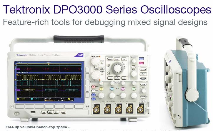
5 Test Equipment in the EE 230 Laboratory (Plus computer, oven, software)
6 Whats inside/on this equipment? Computer (except maybe dc power supply) Some analog circuitry Software Knobs/Buttons Computer Interface Test equipment is becoming very powerful Seldom need most of the capabilities of the equipment Versatility and flexibility makes basic (and most used) operation a little more difficult to learn
7
8 362 Pages
9
10
11
12
13 302 Pages
14
15
16 52 Pages
17
18
19 68 Pages
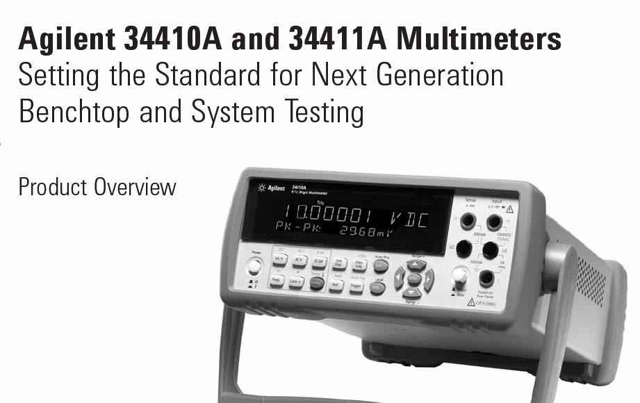
20 When is the voltage reading on the Signal Generator Accurate? Almost Never! When it is reasonably close, (i.e. when not affected by the effects of the output impedance on the actual output) how does the accuracy compare with that of the scope or the digital multimeter measuring the same voltage? Two to three orders of magnitude worse!
21
22
23


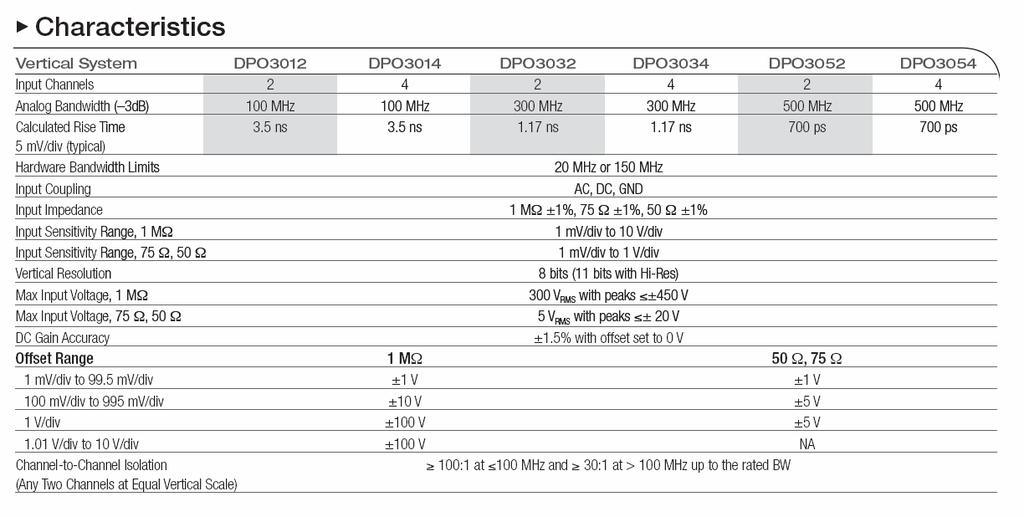
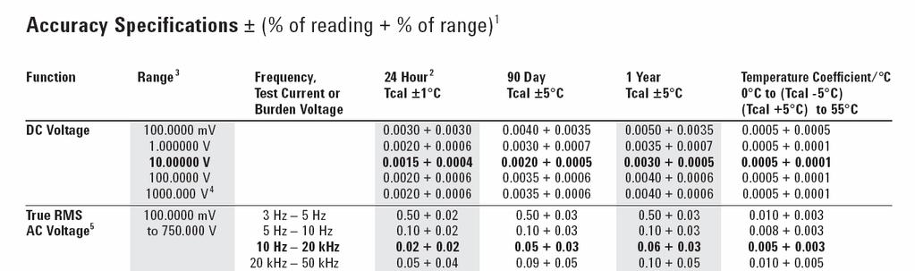
24 Test Equipment in the EE 230 Laboratory 984 Pages! The documentation for the operation of this equipment is extensive Critical that user always know what equipment is doing Consult the users manuals and specifications whenever unsure


 Some")


25 Whats inside/on this equipment? Computer (except maybe dc power supply) Some analog circuitry Software Knobs/Buttons Computer Interface Why is this not the standard interface with a computer?
26 Review from Last Time Properties of Linear Networks T(s) frequency domain ( ) ( s) XOUT s = T(s) X is termed the transfer function IN This is often termed the s-domain or Laplace-domain representation ( ) P T s s=jω = T (jω) Will discuss the frequency domain representations and the more general concept of transfer functions in more detail later
27 Review from Last Time Distortion A system has Harmonic Distortion (often just termed Distortion ) if when a pure sinusoidal input is applied, the Fourier Series representation of the output contains one or more terms at frequencies different than the input frequency A linear system has Frequency Distortion if for any two sinusoidal inputs of magnitude X and X 2, the ratio of the corresponding sinusoidal outputs is not equal to X /X 2. Harmonic distortion is characterized by several different metrics including the Total Harmonic Distortion, Spurious Free Dynamic Range (SFDR) Frequency distortion is characterized by the transfer function, T(s), of the system
28 Review from Last Time Total Harmonic Distortion t+t 2 PAVG = f () t dt T t It can be shown that P = AVG k = 2 A 2 k f() t = Aksin(kωt+θ k) k = Define P to be the power in the fundamental A 2 P= 2 P = Harmonics k = 2 2 A 2 k P THD= THD = HARMONICS k = 2 P A A 2 THD often expressed in db or in % THD =0log THD 2 k db 0 ( ) Can also be expressed relative to signal instead of power
29 Amplifiers: Review from Last Time Amplifiers are circuits that scale a signal by a constant amount Ideally V OUT =AV IN where A is a constant (termed the gain) The dependent sources discussed in EE 20 are amplifiers S V S S M S S I S S M S
30 Amplifiers, Frequency Response, and Transfer Functions IN OUT The frequency dependent gain of a linear circuit or system is often termed the transfer function Sometimes linear circuits are termed Amplifiers or Filters when some specific properties of the relationship between the input and output are of particular interest
31 Example: X IN Linear System X OUT Will go through the mechanics first, then formalize the concepts R V OUT V IN C Obtain the phasor-domain transfer function Obtain the s-domain transfer function Plot the magnitude of the transfer function Plot the phase of the transfer function Obtain the sinusoidal steady state response if V IN =V M sin(2π f t) Do a time-domain analysis of this circuit
32 Example: R V OUT Obtain the phasor-domain transfer function V IN C Phasor-Domain Circuit IN jωc OUT V OUT jωc = V R+ jωc IN V OUT = V +jωrc IN V jω ( ) ( jω) OUT T(jω) P = = VIN +jωrc
33 Example: R V OUT Obtain the s-domain transfer function V IN C s-domain Circuit ( ) ( ) sc V s V s +src OUT T(s) = = IN V sc OUT s VIN s R+ sc ( ) = ( ) VOUT s VIN s +src ( ) = ( )
34 Example: R V OUT V IN C sc jωc T(s) = T(jω) P = +src +jωrc Observe: T(s) = s=jω +jωrc Observe: T(s) = T(jω) This property holds for any linear system! s=jω P
35 Example: R V OUT Plot the transfer function magnitude T(s) = +src T(jω) = +jωrc V IN C T(jω) = ( ) 2 + ωrc T( jω) 2 ω RC
36 Example: R V OUT Plot the phase of the transfer function T(s) = +src T(jω) = +jωrc V IN C T (jω) = -tan ωrc - ( ) T( jω) 0 o -45 o -90 o RC ω
37 Example: R V OUT Obtain the sinusoidal steady-state response if V IN =V M sin(2π f t) V IN C Need a theorem that expresses the sinusoidal steady-state response
38 Key Theorem: Theorem: The steady-state response of a linear network to a sinusoidal excitation of V IN =V M sin(ωt+γ) is given by OUT ( ) V t = V T jω sin ωt+γ+ T jω () ( ) ( ) m This is a very important theorem and is one of the major reasons phasor analysis was studied in EE 20 The sinusoidal steady state response is completely determined by T(jω) The sinusoidal steady state response can be written by inspection from the T jω T( jω ) ( ) and plots T(s) s=jω = T(jω) P
39 Example: Obtain the sinusoidal steady-state response if V IN =V M sin(2π f t) T(jω) = ( ) 2 + ωrc T (jω) = -tan ωrc - ( ) Thus, from the previous theorem with γ=0 OUT ( ) V t = V T jω sin ωt+γ+ T jω () ( ) ( ) m V () OUT t = Vm sin ωt - tan ωrc 2 + ωrc ( ) ( - ( ))
40 Observations: Authors of current electronics textbooks do not talk about phasors or T P (jω) This is consistent with the industry when discussing electronic circuits and systems The sinusoidal steady state response is of considerable concern in electronic circuits and is used extensively in the text for this cours Authors and industry use the concept of the transfer function T(s) when characterizing the frequency-dependent performance of linear circuits and systems
41 Questions Why is T(s) used instead of T P (jω) in the electronics field? What is T(s)? Why was T P (jω) emphasized in EE 20 instead of T(s) for characterizing the frequency dependence of linear networks?
42 Example: Do a time-domain analysis of this circuit ( ) ( ) VIN t -VOUT t it= () R () ( ) V it C d t OUT IN = dt () = n ( + ) V t V si ωt γ M Complete set of differential equations that can be solved to obtain V OUT (t) One way to solve this is to use Laplace Transforms I = scv OUT VIN -VOUT = IR ( sinγ ) s + ωcosγ VIN = V M 2 2 s + ω
43 Example: Do a time-domain analysis of this circuit I = scv OUT VIN -VOUT = IR ( sinγ ) s + ωcosγ VIN = V M 2 2 s + ω With some manipulations, can get expression for V OUT ( sinγ) s + ωcosγ V OUT = VM 2 2 s + ω + src With some more manipulations, we can take inverse Laplace transform to get sinγ ωrc t - () RC V OUT t = VM - e V M sin( ωt + γ tan 2 ( ωrc) ) + 2 ( RC) tanγ + ( ωrc )
44 Example: Do a time-domain analysis of this circuit sinγ ωrc t - () RC V OUT t = VM - e V M sin( ωt + γ tan 2 ( ωrc) ) + 2 ( RC) tanγ + ( ωrc ) Neglecting the natural response to obtain the sinusoidal steady state response, we obtain (with γ = 0) VOUT () t = V M sin ωt ωrc 2 + ( ωrc ) ( tan ( )) Note this is the same response as was obtained with the two previous solutons
45 Formalization of sinusoidal steady-state analysis phasor-domain approach L C jωl jωc All other components unchanged ( ) X = T jω X (this equation not needed) OUT P IN OUT ( ) ( ) = ( ) ( ) X t X T jω sin ωt + θ + T jω M
46 Formalization of sinusoidal steady-state analysis s-domain approach ( ) = ( ) X t X sin ωt + θ X X i (t) i (t) IN M s Transform X i (S) s-domain Circuit Circuit Analysis KVL, KCL L C sl sc All other components unchanged s Transform X i (S) s-domain Circuit Circuit Analysis KVL, KCL Set of Linear equations in s Set of Linear equations in s Solution of Linear Equations Solution of Linear Equations X OUT (S) T(s) Inverse s Transform X ( ) = T jω X OUT P IN (this equation not needed) X OUT (S) T(s) Inverse s Transform X OUT (t) general X OUT (t) ( ) XOUT ( t) = XM T( jω) sin ωt + θ + T ( jω) Sinusoidal steady state
47 Formalization of sinusoidal steady-state analysis X i (t) = X M sin(ωt+θ) X i (S) s Transform Phasor Transform X i (jω) s-domain Circuit Time Domain Circuit Phasor Domain Circuit Circuit Analysis KVL, KCL Circuit Analysis KVL, KCL Circuit Analysis KVL, KCL Set of Linear equations in s Set of Differential Equations Set of Linear equations in jω Solution of Linear Equations Solution of Differential Equations Solution of Linear Equations T(s) T P (jω) X OUT (S) Inverse s Transform Inverse Phasor Transform X OUT (jω) X OUT (t)
48 Which of the methods is most widely used? X i (t) = X M sin(ωt+θ) X i (S) s Transform Phasor Transform X i (jω) s-domain Circuit Time Domain Circuit Phasor Domain Circuit Circuit Analysis KVL, KCL Circuit Analysis KVL, KCL Circuit Analysis KVL, KCL Set of Linear equations in s Set of Differential Equations Set of Linear equations in jω Solution of Linear Equations Solution of Differential Equations Solution of Linear Equations T(s) T P (jω) X OUT (S) Inverse s Transform Inverse Phasor Transform X OUT (jω) X OUT (t) s-domain analysis almost totally dominates the electronics fields and most systems fields
49 Formalization of sinusoidal steady-state analysis - Summary s-domain The Preferred Approach ( ) = ( ) X t X sin ωt + θ IN M X i (t) s Transform L C sl sc All other components unchanged X i (S) s-domain Circuit Circuit Analysis KVL, KCL Set of Linear equations in s Solution of Linear Equations OUT ( ) () = ( ) ( ) X t X T jω sin ωt + θ + T jω M X OUT (S) T(s) Inverse s Transform X OUT (t)
50 Filters: A filter is an amplifier that ideally has a frequency dependent gain Simply a different name for an amplifier that typically has an ideal magnitude or phase response that is not flat Some standard filter responses with accepted nomenclature T( jω) T( jω) T( jω) T( jω) T( jω) T( jω)
51 Summary of frequency response appears on posted notes
ECEN 325 Electronics
 ECEN 325 Electronics Introduction Dr. Aydın İlker Karşılayan Texas A&M University Department of Electrical and Computer Engineering Ohm s Law i R i R v 1 v v 2 v v 1 v 2 v = v 1 v 2 v = v 1 v 2 v = ir
OPERATIONAL AMPLIFIER APPLICATIONS
 OPERATIONAL AMPLIFIER APPLICATIONS 2.1 The Ideal Op Amp (Chapter 2.1) Amplifier Applications 2.2 The Inverting Configuration (Chapter 2.2) 2.3 The Non-inverting Configuration (Chapter 2.3) 2.4 Difference
EE348L Lecture 1. EE348L Lecture 1. Complex Numbers, KCL, KVL, Impedance,Steady State Sinusoidal Analysis. Motivation
 EE348L Lecture 1 Complex Numbers, KCL, KVL, Impedance,Steady State Sinusoidal Analysis 1 EE348L Lecture 1 Motivation Example CMOS 10Gb/s amplifier Differential in,differential out, 5 stage dccoupled,broadband
Chapter 5 Steady-State Sinusoidal Analysis
 Chapter 5 Steady-State Sinusoidal Analysis Chapter 5 Steady-State Sinusoidal Analysis 1. Identify the frequency, angular frequency, peak value, rms value, and phase of a sinusoidal signal. 2. Solve steady-state
Chapter 10: Sinusoidal Steady-State Analysis
 Chapter 10: Sinusoidal Steady-State Analysis 1 Objectives : sinusoidal functions Impedance use phasors to determine the forced response of a circuit subjected to sinusoidal excitation Apply techniques
Sinusoidal Steady-State Analysis
 Chapter 4 Sinusoidal Steady-State Analysis In this unit, we consider circuits in which the sources are sinusoidal in nature. The review section of this unit covers most of section 9.1 9.9 of the text.
EE 435. Lecture 28. Data Converters Linearity INL/DNL Spectral Performance
 EE 435 Lecture 8 Data Converters Linearity INL/DNL Spectral Performance Performance Characterization of Data Converters Static characteristics Resolution Least Significant Bit (LSB) Offset and Gain Errors
K.K. Gan L3: R-L-C AC Circuits. amplitude. Volts. period. -Vo
 Lecture 3: R-L-C AC Circuits AC (Alternative Current): Most of the time, we are interested in the voltage at a point in the circuit will concentrate on voltages here rather than currents. We encounter
EE292: Fundamentals of ECE
 EE292: Fundamentals of ECE Fall 2012 TTh 10:00-11:15 SEB 1242 Lecture 20 121101 http://www.ee.unlv.edu/~b1morris/ee292/ 2 Outline Chapters 1-3 Circuit Analysis Techniques Chapter 10 Diodes Ideal Model
EE292: Fundamentals of ECE
 EE292: Fundamentals of ECE Fall 2012 TTh 10:00-11:15 SEB 1242 Lecture 18 121025 http://www.ee.unlv.edu/~b1morris/ee292/ 2 Outline Review RMS Values Complex Numbers Phasors Complex Impedance Circuit Analysis
Refinements to Incremental Transistor Model
 Refinements to Incremental Transistor Model This section presents modifications to the incremental models that account for non-ideal transistor behavior Incremental output port resistance Incremental changes
Fall 2011 ME 2305 Network Analysis. Sinusoidal Steady State Analysis of RLC Circuits
 Fall 2011 ME 2305 Network Analysis Chapter 4 Sinusoidal Steady State Analysis of RLC Circuits Engr. Humera Rafique Assistant Professor humera.rafique@szabist.edu.pk Faculty of Engineering (Mechatronics)
School of Electrical and Computer Engineering ECE2040 Dr. George F. Riley Summer 2007, GT Lorraine Analysis of LRC with Sinusoidal Sources
 School of Electrical and Computer Engineering ECE2040 Dr. George F. Riley Summer 2007, GT Lorraine Analysis of LRC with Sinusoidal Sources In chapter 8 in the textbook, we determined that if the forcing
09/29/2009 Reading: Hambley Chapter 5 and Appendix A
 EE40 Lec 10 Complex Numbers and Phasors Prof. Nathan Cheung 09/29/2009 Reading: Hambley Chapter 5 and Appendix A Slide 1 OUTLINE Phasors as notation for Sinusoids Arithmetic with Complex Numbers Complex
EE 435. Lecture 30. Data Converters. Spectral Performance
 EE 435 Lecture 30 Data Converters Spectral Performance . Review from last lecture. INL Often Not a Good Measure of Linearity Four identical INL with dramatically different linearity X OUT X OUT X REF X
Sinusoids and Phasors
 CHAPTER 9 Sinusoids and Phasors We now begins the analysis of circuits in which the voltage or current sources are time-varying. In this chapter, we are particularly interested in sinusoidally time-varying
To find the step response of an RC circuit
 To find the step response of an RC circuit v( t) v( ) [ v( t) v( )] e tt The time constant = RC The final capacitor voltage v() The initial capacitor voltage v(t ) To find the step response of an RL circuit
REACTANCE. By: Enzo Paterno Date: 03/2013
 REACTANCE REACTANCE By: Enzo Paterno Date: 03/2013 5/2007 Enzo Paterno 1 RESISTANCE - R i R (t R A resistor for all practical purposes is unaffected by the frequency of the applied sinusoidal voltage or
Use of a Notch Filter in a Tuned Mode for LISA.
 Use of a Notch Filter in a Tuned Mode for LISA. Giorgio Fontana September 00 Abstract. During interferometric measurements the proof mass must be free from any controlling force within a given observation
Chapter 10: Sinusoids and Phasors
 Chapter 10: Sinusoids and Phasors 1. Motivation 2. Sinusoid Features 3. Phasors 4. Phasor Relationships for Circuit Elements 5. Impedance and Admittance 6. Kirchhoff s Laws in the Frequency Domain 7. Impedance
Phasors: Impedance and Circuit Anlysis. Phasors
 Phasors: Impedance and Circuit Anlysis Lecture 6, 0/07/05 OUTLINE Phasor ReCap Capacitor/Inductor Example Arithmetic with Complex Numbers Complex Impedance Circuit Analysis with Complex Impedance Phasor
EE40 Lecture 11 Josh Hug 7/19/2010
 EE40 Lecture Josh 7/9/200 Logistical Things Lab 4 tomorrow Lab 5 (active filter lab) on Wednesday Prototype for future lab for EE40 Prelab is very short, sorry. Please give us our feedback Google docs
Prof. Shayla Sawyer CP08 solution
 What does the time constant represent in an exponential function? How do you define a sinusoid? What is impedance? How is a capacitor affected by an input signal that changes over time? How is an inductor
Homework Assignment 11
 Homework Assignment Question State and then explain in 2 3 sentences, the advantage of switched capacitor filters compared to continuous-time active filters. (3 points) Continuous time filters use resistors
Refresher course on Electrical fundamentals (Basics of A.C. Circuits) by B.M.Vyas
 by B.M.Vyas") Refresher course on Electrical fundamentals (Basics of A.C. Circuits) by B.M.Vyas A specifically designed programme for Da Afghanistan Breshna Sherkat (DABS) Afghanistan 1 Areas Covered Under this Module
Refresher course on Electrical fundamentals (Basics of A.C. Circuits) by B.M.Vyas A specifically designed programme for Da Afghanistan Breshna Sherkat (DABS) Afghanistan 1 Areas Covered Under this Module
Sinusoidal Steady State Analysis (AC Analysis) Part I
 Part I") Sinusoidal Steady State Analysis (AC Analysis) Part I Amin Electronics and Electrical Communications Engineering Department (EECE) Cairo University elc.n102.eng@gmail.com http://scholar.cu.edu.eg/refky/
Sinusoidal Steady State Analysis (AC Analysis) Part I Amin Electronics and Electrical Communications Engineering Department (EECE) Cairo University elc.n102.eng@gmail.com http://scholar.cu.edu.eg/refky/
Circuit Analysis-III. Circuit Analysis-II Lecture # 3 Friday 06 th April, 18
 Circuit Analysis-III Sinusoids Example #1 ü Find the amplitude, phase, period and frequency of the sinusoid: v (t ) =12cos(50t +10 ) Signal Conversion ü From sine to cosine and vice versa. ü sin (A ± B)
Sinusoidal Steady State Analysis
 Sinusoidal Steady State Analysis 9 Assessment Problems AP 9. [a] V = 70/ 40 V [b] 0 sin(000t +20 ) = 0 cos(000t 70 ).. I = 0/ 70 A [c] I =5/36.87 + 0/ 53.3 =4+j3+6 j8 =0 j5 =.8/ 26.57 A [d] sin(20,000πt
EE 40: Introduction to Microelectronic Circuits Spring 2008: Midterm 2
 EE 4: Introduction to Microelectronic Circuits Spring 8: Midterm Venkat Anantharam 3/9/8 Total Time Allotted : min Total Points:. This is a closed book exam. However, you are allowed to bring two pages
Designing Information Devices and Systems II Fall 2018 Elad Alon and Miki Lustig Discussion 5A
 EECS 6B Designing Information Devices and Systems II Fall 208 Elad Alon and Miki Lustig Discussion 5A Transfer Function When we write the transfer function of an arbitrary circuit, it always takes the
Review of 1 st Order Circuit Analysis
 ECEN 60 Circuits/Electronics Spring 007-7-07 P. Mathys Review of st Order Circuit Analysis First Order Differential Equation Consider the following circuit with input voltage v S (t) and output voltage
Chapter 9 Objectives
 Chapter 9 Engr8 Circuit Analysis Dr Curtis Nelson Chapter 9 Objectives Understand the concept of a phasor; Be able to transform a circuit with a sinusoidal source into the frequency domain using phasor
Electric Circuits II Sinusoidal Steady State Analysis. Dr. Firas Obeidat
 Electric Circuits II Sinusoidal Steady State Analysis Dr. Firas Obeidat 1 Table of Contents 1 2 3 4 5 Nodal Analysis Mesh Analysis Superposition Theorem Source Transformation Thevenin and Norton Equivalent
AC analysis - many examples
 AC analysis - many examples The basic method for AC analysis:. epresent the AC sources as complex numbers: ( ). Convert resistors, capacitors, and inductors into their respective impedances: resistor Z
Basic Electronics. Introductory Lecture Course for. Technology and Instrumentation in Particle Physics Chicago, Illinois June 9-14, 2011
 Basic Electronics Introductory Lecture Course for Technology and Instrumentation in Particle Physics 2011 Chicago, Illinois June 9-14, 2011 Presented By Gary Drake Argonne National Laboratory Session 2
Chapter 3. Loop and Cut-set Analysis
 Chapter 3. Loop and Cut-set Analysis By: FARHAD FARADJI, Ph.D. Assistant Professor, Electrical Engineering, K.N. Toosi University of Technology http://wp.kntu.ac.ir/faradji/electriccircuits2.htm References:
Sinusoidal Steady-state Analysis
 Siusoidal Steady-state Aalysis Complex umber reviews Phasors ad ordiary differetial equatios Complete respose ad siusoidal steady-state respose Cocepts of impedace ad admittace Siusoidal steady-state aalysis
Radio Frequency Electronics
 Radio Frequency Electronics Preliminaries III Lee de Forest Born in Council Bluffs, Iowa in 1873 Had 180 patents Invented the vacuum tube that allows for building electronic amplifiers Vacuum tube started
EE100Su08 Lecture #11 (July 21 st 2008)
") EE100Su08 Lecture #11 (July 21 st 2008) Bureaucratic Stuff Lecture videos should be up by tonight HW #2: Pick up from office hours today, will leave them in lab. REGRADE DEADLINE: Monday, July 28 th 2008,
EE100Su08 Lecture #11 (July 21 st 2008) Bureaucratic Stuff Lecture videos should be up by tonight HW #2: Pick up from office hours today, will leave them in lab. REGRADE DEADLINE: Monday, July 28 th 2008,
EE 435. Lecture 2: Basic Op Amp Design. - Single Stage Low Gain Op Amps
 EE 435 ecture 2: Basic Op Amp Design - Single Stage ow Gain Op Amps 1 Review from last lecture: How does an amplifier differ from an operational amplifier?? Op Amp Amplifier Amplifier used in open-loop
ECE Networks & Systems
 ECE 342 1. Networks & Systems Jose E. Schutt Aine Electrical & Computer Engineering University of Illinois jschutt@emlab.uiuc.edu 1 What is Capacitance? 1 2 3 Voltage=0 No Charge No Current Voltage build
Electric Circuit Theory
 Electric Circuit Theory Nam Ki Min nkmin@korea.ac.kr 010-9419-2320 Chapter 11 Sinusoidal Steady-State Analysis Nam Ki Min nkmin@korea.ac.kr 010-9419-2320 Contents and Objectives 3 Chapter Contents 11.1
EE 435. Lecture 29. Data Converters. Linearity Measures Spectral Performance
 EE 435 Lecture 9 Data Converters Linearity Measures Spectral Performance Linearity Measurements (testing) Consider ADC V IN (t) DUT X IOUT V REF Linearity testing often based upon code density testing
Chapter 10 Sinusoidal Steady State Analysis Chapter Objectives:
 Chapter 10 Sinusoidal Steady State Analysis Chapter Objectives: Apply previously learn circuit techniques to sinusoidal steady-state analysis. Learn how to apply nodal and mesh analysis in the frequency
Review of Linear Time-Invariant Network Analysis
 D1 APPENDIX D Review of Linear Time-Invariant Network Analysis Consider a network with input x(t) and output y(t) as shown in Figure D-1. If an input x 1 (t) produces an output y 1 (t), and an input x
Sinusoidal steady-state analysis
 Sinusoidal steady-state analysis From our previous efforts with AC circuits, some patterns in the analysis started to appear. 1. In each case, the steady-state voltages or currents created in response
First and Second Order Circuits. Claudio Talarico, Gonzaga University Spring 2015
 First and Second Order Circuits Claudio Talarico, Gonzaga University Spring 2015 Capacitors and Inductors intuition: bucket of charge q = Cv i = C dv dt Resist change of voltage DC open circuit Store voltage
EECS 117 Lecture 3: Transmission Line Junctions / Time Harmonic Excitation
 EECS 117 Lecture 3: Transmission Line Junctions / Time Harmonic Excitation Prof. Niknejad University of California, Berkeley University of California, Berkeley EECS 117 Lecture 3 p. 1/23 Transmission Line
EE221 Circuits II. Chapter 14 Frequency Response
 EE22 Circuits II Chapter 4 Frequency Response Frequency Response Chapter 4 4. Introduction 4.2 Transfer Function 4.3 Bode Plots 4.4 Series Resonance 4.5 Parallel Resonance 4.6 Passive Filters 4.7 Active
EE221 Circuits II. Chapter 14 Frequency Response
 EE22 Circuits II Chapter 4 Frequency Response Frequency Response Chapter 4 4. Introduction 4.2 Transfer Function 4.3 Bode Plots 4.4 Series Resonance 4.5 Parallel Resonance 4.6 Passive Filters 4.7 Active
EE 435. Lecture 2: Basic Op Amp Design. - Single Stage Low Gain Op Amps
 EE 435 ecture 2: Basic Op mp Design - Single Stage ow Gain Op mps 1 Review from last lecture: How does an amplifier differ from an operational amplifier?? Op mp mplifier mplifier used in open-loop applications
EE GATE
 EE GATE-009 www.gateforum.com GATE - 009 Answer Keys 1 B C 3 A 4 D 5 B 6 D 7 A 8 A 9 B 10 D 11 D 1 B 13 A 14 C 15 B 16 C 17 C 18 D 19 B 0 C 1 D C 3 A 4 A 5 D 6 C 7 D 8 D 9 B 30 C 31 C 3 A 33 A 34 B 35
Circuit Analysis Using Fourier and Laplace Transforms
 EE2015: Electrical Circuits and Networks Nagendra Krishnapura https://wwweeiitmacin/ nagendra/ Department of Electrical Engineering Indian Institute of Technology, Madras Chennai, 600036, India July-November
Sinusoidal Steady State Analysis (AC Analysis) Part II
 Part II") Sinusoidal Steady State Analysis (AC Analysis) Part II Amin Electronics and Electrical Communications Engineering Department (EECE) Cairo University elc.n102.eng@gmail.com http://scholar.cu.edu.eg/refky/
Sinusoidal Steady State Analysis (AC Analysis) Part II Amin Electronics and Electrical Communications Engineering Department (EECE) Cairo University elc.n102.eng@gmail.com http://scholar.cu.edu.eg/refky/
Network Graphs and Tellegen s Theorem
 Networ Graphs and Tellegen s Theorem The concepts of a graph Cut sets and Kirchhoff s current laws Loops and Kirchhoff s voltage laws Tellegen s Theorem The concepts of a graph The analysis of a complex
AC analysis. EE 201 AC analysis 1
 AC analysis Now we turn to circuits with sinusoidal sources. Earlier, we had a brief look at sinusoids, but now we will add in capacitors and inductors, making the story much more interesting. What are
Principles of Bioelectronics Design Lecture #1
 Principles of Bioelectronics Design Lecture #1 3.5- יסודות תכן ביו-חשמלי 334011 נקודות זיקוי מרצה: פרופסור ראמז דאניאל בניין אמרסון קומה 7 שעות קבלה:לפי תיאום מראש ramizda@bm.technion.ac.il מתרגל : ירון
Dynamic circuits: Frequency domain analysis
 Electronic Circuits 1 Dynamic circuits: Contents Free oscillation and natural frequency Transfer functions Frequency response Bode plots 1 System behaviour: overview 2 System behaviour : review solution
Frequency Response. Re ve jφ e jωt ( ) where v is the amplitude and φ is the phase of the sinusoidal signal v(t). ve jφ
 where v is the amplitude and φ is the phase of the sinusoidal signal v(t). ve jφ") 27 Frequency Response Before starting, review phasor analysis, Bode plots... Key concept: small-signal models for amplifiers are linear and therefore, cosines and sines are solutions of the linear differential
27 Frequency Response Before starting, review phasor analysis, Bode plots... Key concept: small-signal models for amplifiers are linear and therefore, cosines and sines are solutions of the linear differential
Transmission Lines in the Frequency Domain
 Berkeley Transmission Lines in the Frequency Domain Prof. Ali M. Niknejad U.C. Berkeley Copyright c 2016 by Ali M. Niknejad August 30, 2017 1 / 38 Why Sinusoidal Steady-State? 2 / 38 Time Harmonic Steady-State
Electrical Circuits Lab Series RC Circuit Phasor Diagram
 Electrical Circuits Lab. 0903219 Series RC Circuit Phasor Diagram - Simple steps to draw phasor diagram of a series RC circuit without memorizing: * Start with the quantity (voltage or current) that is
Lecture 23: NorCal 40A Power Amplifier. Thermal Modeling.
 Whites, EE 322 Lecture 23 Page 1 of 13 Lecture 23: NorCal 40A Power Amplifier. Thermal Modeling. Recall from the last lecture that the NorCal 40A uses a Class C power amplifier. From Fig. 10.3(b) the collector
Input and Output Impedances with Feedback
 EE 3 Lecture Basic Feedback Configurations Generalized Feedback Schemes Integrators Differentiators First-order active filters Second-order active filters Review from Last Time Input and Output Impedances
Lecture 4: Feedback and Op-Amps
 Lecture 4: Feedback and Op-Amps Last time, we discussed using transistors in small-signal amplifiers If we want a large signal, we d need to chain several of these small amplifiers together There s a problem,
Module 4. Single-phase AC Circuits
 Module 4 Single-phase AC Circuits Lesson 14 Solution of Current in R-L-C Series Circuits In the last lesson, two points were described: 1. How to represent a sinusoidal (ac) quantity, i.e. voltage/current
Phasor Diagram. Figure 1: Phasor Diagram. A φ. Leading Direction. θ B. Lagging Direction. Imag. Axis Complex Plane. Real Axis
 1 16.202: PHASORS Consider sinusoidal source i(t) = Acos(ωt + φ) Using Eulers Notation: Acos(ωt + φ) = Re[Ae j(ωt+φ) ] Phasor Representation of i(t): = Ae jφ = A φ f v(t) = Bsin(ωt + ψ) First convert the
Chapter 10: Sinusoidal Steady-State Analysis
 Chapter 10: Sinusoidal Steady-State Analysis 10.1 10.2 10.3 10.4 10.5 10.6 10.9 Basic Approach Nodal Analysis Mesh Analysis Superposition Theorem Source Transformation Thevenin & Norton Equivalent Circuits
Chapter 5 Frequency Domain Analysis of Systems
 Chapter 5 Frequency Domain Analysis of Systems CT, LTI Systems Consider the following CT LTI system: xt () ht () yt () Assumption: the impulse response h(t) is absolutely integrable, i.e., ht ( ) dt< (this
Lectures 16 & 17 Sinusoidal Signals, Complex Numbers, Phasors, Impedance & AC Circuits. Nov. 7 & 9, 2011
 Lectures 16 & 17 Sinusoidal Signals, Complex Numbers, Phasors, Impedance & AC Circuits Nov. 7 & 9, 2011 Material from Textbook by Alexander & Sadiku and Electrical Engineering: Principles & Applications,
1.3 Sinusoidal Steady State
 1.3 Sinusoidal Steady State Electromagnetics applications can be divided into two broad classes: Time-domain: Excitation is not sinusoidal (pulsed, broadband, etc.) Ultrawideband communications Pulsed
Filters and Tuned Amplifiers
 Filters and Tuned Amplifiers Essential building block in many systems, particularly in communication and instrumentation systems Typically implemented in one of three technologies: passive LC filters,
THE FOURIER TRANSFORM (Fourier series for a function whose period is very, very long) Reading: Main 11.3
 Reading: Main 11.3") THE FOURIER TRANSFORM (Fourier series for a function whose period is very, very long) Reading: Main 11.3 Any periodic function f(t) can be written as a Fourier Series a 0 2 + a n cos( nωt) + b n sin n
THE FOURIER TRANSFORM (Fourier series for a function whose period is very, very long) Reading: Main 11.3 Any periodic function f(t) can be written as a Fourier Series a 0 2 + a n cos( nωt) + b n sin n
Circuits. Fawwaz T. Ulaby, Michel M. Maharbiz, Cynthia M. Furse. Solutions to the Exercises
 Circuits by Fawwaz T. Ulaby, Michel M. Maharbiz, Cynthia M. Furse Solutions to the Exercises Chapter 1: Circuit Terminology Chapter 2: Resisitive Circuits Chapter 3: Analysis Techniques Chapter 4: Operational
Lecture 05 Power in AC circuit
 CA2627 Building Science Lecture 05 Power in AC circuit Instructor: Jiayu Chen Ph.D. Announcement 1. Makeup Midterm 2. Midterm grade Grade 25 20 15 10 5 0 10 15 20 25 30 35 40 Grade Jiayu Chen, Ph.D. 2
GATE : , Copyright reserved. Web:www.thegateacademy.com
 GATE-2016 Index 1. Question Paper Analysis 2. Question Paper & Answer keys : 080-617 66 222, info@thegateacademy.com Copyright reserved. Web:www.thegateacademy.com ANALYSIS OF GATE 2016 Electrical Engineering
EECE 301 Signals & Systems Prof. Mark Fowler
 EECE 3 Signals & Systems Prof. Mark Fowler Note Set #9 C-T Systems: Laplace Transform Transfer Function Reading Assignment: Section 6.5 of Kamen and Heck /7 Course Flow Diagram The arrows here show conceptual
I. Frequency Response of Voltage Amplifiers
 I. Frequency Response of Voltage Amplifiers A. Common-Emitter Amplifier: V i SUP i OUT R S V BIAS R L v OUT V Operating Point analysis: 0, R s 0, r o --->, r oc --->, R L ---> Find V BIAS such that I C
Physics 405/505 Digital Electronics Techniques. University of Arizona Spring 2006 Prof. Erich W. Varnes
 Physics 405/505 Digital Electronics Techniques University of Arizona Spring 2006 Prof. Erich W. Varnes Administrative Matters Contacting me I will hold office hours on Tuesday from 1-3 pm Room 420K in
1 Phasors and Alternating Currents
 Physics 4 Chapter : Alternating Current 0/5 Phasors and Alternating Currents alternating current: current that varies sinusoidally with time ac source: any device that supplies a sinusoidally varying potential
Superposition (take 3)
") Superposition (take 3) Previously, we looked at how to analyze an AC to DC converter and a Buck converter. To solve these circuits, we changed the problem so that the input contained A DC signal, and An
Superposition (take 3) Previously, we looked at how to analyze an AC to DC converter and a Buck converter. To solve these circuits, we changed the problem so that the input contained A DC signal, and An
Electronic Power Conversion
 Electronic Power Conversion Review of Basic Electrical and Magnetic Circuit Concepts Challenge the future 3. Review of Basic Electrical and Magnetic Circuit Concepts Notation Electric circuits Steady state
EE 330 Lecture 22. Small Signal Modelling Operating Points for Amplifier Applications Amplification with Transistor Circuits
 EE 330 Lecture 22 Small Signal Modelling Operating Points for Amplifier Applications Amplification with Transistor Circuits Exam 2 Friday March 9 Exam 3 Friday April 13 Review Session for Exam 2: 6:00
EE40 Homework #6. Due Oct 15 (Thursday), 12:00 noon in Cory 240
, 12:00 noon in Cory 240") Fall 2009 EE40 Homework #6 Due Oct 15 (Thursday), 12:00 noon in Cory 240 Reading Assignments Chapter 5 of Hambley textbook. Section 5.7 on Three-Phase circuit is optional Sections 6.1-6.5 of Hambley textbook
Fall 2009 EE40 Homework #6 Due Oct 15 (Thursday), 12:00 noon in Cory 240 Reading Assignments Chapter 5 of Hambley textbook. Section 5.7 on Three-Phase circuit is optional Sections 6.1-6.5 of Hambley textbook
EE 505 Lecture 10. Spectral Characterization. Part 2 of 2
 EE 505 Lecture 10 Spectral Characterization Part 2 of 2 Review from last lecture Spectral Analysis If f(t) is periodic f(t) alternately f(t) = = A A ( kω t + ) 0 + Aksin θk k= 1 0 + a ksin t k= 1 k= 1
EE 508 Lecture 4. Filter Concepts/Terminology Basic Properties of Electrical Circuits
 EE 58 Lecture 4 Filter Concepts/Terminology Basic Properties of Electrical Circuits Review from Last Time Filter Design Process Establish Specifications - possibly T D (s) or H D (z) - magnitude and phase
Chapter 10: Sinusoidal Steady-State Analysis
 Chapter 0: Sinusoidal Steady-State Analysis Sinusoidal Sources If a circuit is driven by a sinusoidal source, after 5 tie constants, the circuit reaches a steady-state (reeber the RC lab with t τ). Consequently,
Lecture 15: Sinusoidal Steady State (SSS) Analysis or Phasors without a Phasor more or less
 Analysis or Phasors without a Phasor more or less") Spring 18 page 1 Lecture 15: Sinusoidal Steady State (SSS) Analysis or Phasors without a Phasor more or less 1. Definition. A signal f (t) is periodic with period T > 0 if f (t) = f (t + T ) ; the smallest
Spring 18 page 1 Lecture 15: Sinusoidal Steady State (SSS) Analysis or Phasors without a Phasor more or less 1. Definition. A signal f (t) is periodic with period T > 0 if f (t) = f (t + T ) ; the smallest
ECE 45 Average Power Review
 UC San Diego J. Connelly Complex Power ECE 45 Average Power Review When dealing with time-dependent voltage and currents, we have to consider a more general definition of power. We can calculate the instantaneous
R. W. Erickson. Department of Electrical, Computer, and Energy Engineering University of Colorado, Boulder
 R. W. Erickson Department of Electrical, Computer, and Energy Engineering University of Colorado, Boulder 8.1. Review of Bode plots Decibels Table 8.1. Expressing magnitudes in decibels G db = 0 log 10
EE 435 Lecture 44. Switched-Capacitor Amplifiers Other Integrated Filters
 EE 435 Lecture 44 Switched-Capacitor Amplifiers Other Integrated Filters Switched-Capacitor Amplifiers Noninverting Amplifier Inverting Amplifier C A V = C C A V = - C Accurate control of gain is possible
EE40 Midterm Review Prof. Nathan Cheung
 EE40 Midterm Review Prof. Nathan Cheung 10/29/2009 Slide 1 I feel I know the topics but I cannot solve the problems Now what? Slide 2 R L C Properties Slide 3 Ideal Voltage Source *Current depends d on
ECE Circuit Theory. Final Examination. December 5, 2008
 ECE 212 H1F Pg 1 of 12 ECE 212 - Circuit Theory Final Examination December 5, 2008 1. Policy: closed book, calculators allowed. Show all work. 2. Work in the provided space. 3. The exam has 3 problems
15 n=0. zz = re jθ re jθ = r 2. (b) For division and multiplication, it is handy to use the polar representation: z = rejθ. = z 1z 2.
 For division and multiplication, it is handy to use the polar representation: z = rejθ. = z 1z 2.") Professor Fearing EECS0/Problem Set v.0 Fall 06 Due at 4 pm, Fri. Sep. in HW box under stairs (st floor Cory) Reading: EE6AB notes. This problem set should be review of material from EE6AB. (Please note,
Professor Fearing EECS0/Problem Set v.0 Fall 06 Due at 4 pm, Fri. Sep. in HW box under stairs (st floor Cory) Reading: EE6AB notes. This problem set should be review of material from EE6AB. (Please note,
Prerequisites: Successful completion of PHYS 2222 General Physics (Calculus) with a grade of C or better.
 with a grade of C or better.") Prepared by: P. Blake Reviewed by: M. Mayfield Date prepared: March 13, 2017 C&GE approved: April 17, 2017 Board approved: May 10, 2017 Semester effective: Spring 2018 Engineering (ENGR) 2000 Circuit Analysis
Prepared by: P. Blake Reviewed by: M. Mayfield Date prepared: March 13, 2017 C&GE approved: April 17, 2017 Board approved: May 10, 2017 Semester effective: Spring 2018 Engineering (ENGR) 2000 Circuit Analysis
Fourier series. XE31EO2 - Pavel Máša. Electrical Circuits 2 Lecture1. XE31EO2 - Pavel Máša - Fourier Series
 Fourier series Electrical Circuits Lecture - Fourier Series Filtr RLC defibrillator MOTIVATION WHAT WE CAN'T EXPLAIN YET Source voltage rectangular waveform Resistor voltage sinusoidal waveform - Fourier
Chapter 5 Frequency Domain Analysis of Systems
 Chapter 5 Frequency Domain Analysis of Systems CT, LTI Systems Consider the following CT LTI system: xt () ht () yt () Assumption: the impulse response h(t) is absolutely integrable, i.e., ht ( ) dt< (this
Name: Lab: M8 M2 W8 Th8 Th11 Th2 F8. cos( θ) = cos(θ) sin( θ) = sin(θ) sin(θ) = cos. θ (radians) θ (degrees) cos θ sin θ π/6 30
 = cos(θ) sin( θ) = sin(θ) sin(θ) = cos. θ (radians) θ (degrees) cos θ sin θ π/6 30") Name: Lab: M8 M2 W8 Th8 Th11 Th2 F8 Trigonometric Identities cos(θ) = cos(θ) sin(θ) = sin(θ) sin(θ) = cos Cosines and Sines of common angles Euler s Formula θ (radians) θ (degrees) cos θ sin θ 0 0 1 0
Name: Lab: M8 M2 W8 Th8 Th11 Th2 F8 Trigonometric Identities cos(θ) = cos(θ) sin(θ) = sin(θ) sin(θ) = cos Cosines and Sines of common angles Euler s Formula θ (radians) θ (degrees) cos θ sin θ 0 0 1 0
ELECTRICAL ENGINEERING
 ELECTRICAL ENGINEERING Subject Code: EE Course Structure Sections/Units Section A Unit 1 Unit 2 Unit 3 Unit 4 Unit 5 Unit 6 Unit 7 Section B Section C Section D Section E Section F Section G Section H
Delhi Noida Bhopal Hyderabad Jaipur Lucknow Indore Pune Bhubaneswar Kolkata Patna Web: Ph:
 Serial : ND_EE_NW_Analog Electronics_05088 Delhi Noida Bhopal Hyderabad Jaipur Lucknow ndore Pune Bhubaneswar Kolkata Patna Web: E-mail: info@madeeasy.in Ph: 0-4546 CLASS TEST 08-9 ELECTCAL ENGNEENG Subject
Accurate Fourier Analysis for Circuit Simulators
 Accurate Fourier Analysis for Circuit Simulators Kenneth S. Kundert Cadence Design Systems (Based on Presentation to CICC 94) Abstract A new approach to Fourier analysis within the context of circuit simulation