Chapter 6: Series-Parallel Circuits
|
|
|
- Cecil Spencer
- 6 years ago
- Views:
Transcription


1 Chapter 6: Series-Parallel Circuits Instructor: Jean-François MILLITHALER Slide 1
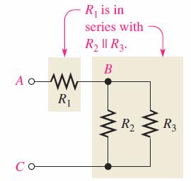
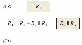
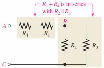
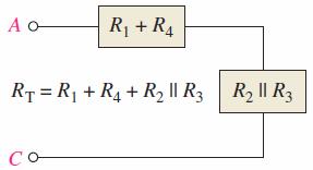
2 Identifying series-parallel relationships Most practical circuits have combinations of series and parallel components. Components that are connected in series will share a common path. Components that are connected in parallel will be connected across the same two nodes. Slide 2
3 Combination circuits Most practical circuits have various combinations of series and parallel components. You can frequently simplify analysis by combining series and parallel components. An important analysis method is to form an equivalent circuit. An equivalent circuit is one that has characteristics that are electrically the same as another circuit but is generally simpler. Slide 3
4 Identifying series-parallel relationships Slide 4
5 Identifying series-parallel relationships Slide 5

6 Identifying series-parallel relationships Slide 6

7 Identifying series-parallel relationships Slide 7
8 Examples R T = R 1 + R 5 + R 4 (R 2 + R 3 ) R T = R 1 + R 2 R 3 + R 4 R 5 Slide 8
9 Total resistance Identifying the components Total resistance R T = R 1 + R 2 R 3 = = 60 W Slide 9
10 Example Find R T = 148 W Slide 10
11 Total Current 5 V Ohm s law: I T = V S R T Find I 4 = 3.45 ma (I 2 = 9.29 ma) Slide 11
12 Voltage Relationships Find R AB, R BC & R T Find V 1, V 2, V 3, V 4, and V 5 V 1 = V 2 = 5.15 V V 3 = 4.85 V V 4 = 1.58 V V 5 = 3.27 V Slide 12
13 Slide 13
14 THE WHEATSTONE BRIDGE Sir Charles Wheatstone, Used to precisely measure resistance Used also in conjunction with transducers Transducer = sensor. Change physical parameter in resistance, for example. Slide 14
15 THE WHEATSTONE BRIDGE The balanced bridge Balanced bridge when the output V OUT = 0V We have then V 1 =V 2 and V 3 =V 4 Therefore V 1 V 3 = V 2 V 4 and I 1 R 1 I 3 R 3 = I 2 R 2 I 4 R 4 Since I 1 = I 3 and I 2 = I 4 We got R 1 R 3 = R 2 R 4 and finally R 1 = R 3 R 2 R 4 Bridge to find an unknown resistance Slide 15
16 THE WHEATSTONE BRIDGE Example Determine the value of R X. The bridge is balanced (V OUT = 0 V) when R V is set at 1200 W R X = R V R 2 R 4 = = 1800 Ω Slide 16
17 THE WHEATSTONE BRIDGE The unbalanced bridge Unbalanced bridge when the output V OUT 0V Used to measure several types of physical quantities such as mechanical strain, temperature, or pressure. Connecting the transducer in one leg of the bridge. The resistance of the transducer changes proportionally to the changes in the parameter that it is measuring. If the bridge is balanced at a known point, then the amount of deviation indicates the amount of change in the parameter being measured. Therefore, the value of the parameter being measured can be determined by the amount that the bridge is unbalanced Slide 17
18 THE WHEATSTONE BRIDGE Example Determine the output voltage of the temperature-measuring bridge circuit if the thermistor is exposed to a temperature of 50ºC and its resistance at 25ºC is 1.0 kω. Assume the resistance of the thermistor decreases to 900 Ω at 50 C. At 25ºC the bridge is balanced. At 50ºC the bridge is unbalanced. We can apply the voltage-divider formula to the left and right sides. V A = R 3 R 3 +R therm V S = 1kΩ 1kΩ+900Ω 12 V = 6.32 V V B = R 4 V R 2 +R S = 1kΩ 4 2kΩ 12 V = 6. V V OUT = V A -V B = = 0.32 V at 50ºC Slide 18
19 Slide 19
20 THEVENIN s Theorem Léon Charles Thévenin, French Engineer, What for? To simplify Electric Engineer s Life!!! Simplify a complicate series-parallel circuit into an equivalent circuit Consists of an equivalent voltage source V TH And an equivalent resistance R TH Slide 20

21 THEVENIN s Theorem The Thevenin equivalent voltage V TH is the open circuit (no-load) voltage between two specified output terminals in a circuit. The Thevenin equivalent resistance R TH is the total resistance appearing between two specified output terminals in a circuit with all sources replaced by their internal resistances (which for an ideal voltage source is zero). Slide 21
22 Three steps: #1 Circuit complicate Output terminals Step 1: Find V TH = Find the voltage between A and B Slide 22
23 Three steps: #2 Step 2: Find R TH Short-circuiting the battery Find the resistance between A and B Slide 23
24 Three steps: #3 Step 3: Combining both V TH and R TH Thevenin equivalent circuit Slide 24
25 Depends on the viewpoint Slide 25
26 Depends on the viewpoint Slide 26
27 Thevenizing a Bridge Circuit Slide 27
28 Slide 31

29 Maximum Power Transfer Theorem For a given source voltage, maximum power is transferred from a source to a load when the load resistance is equal to the internal source resistance. Maximum power is transferred to the load when R L = R S. Slide 32
30 Maximum Power Transfer Theorem Example: Determine the load power for different values of the variable load resistance [0:125] W Solution: Using Ohm s law and Power Formula For R L = 0 W I = V S = 10 = 133 ma R S + R L P L = I 2 R L = = 0 W Slide 33
31 Maximum Power Transfer Theorem P L (mw) 400 Maximum for R L =R S For R L = 0 W : P L = 0 W For R L = 25 W : P L = 250 mw 100 For R L = 50 W : P L = 320 mw For R L = 75 W : P L = 334 mw For R L = 100 W : P L = 326 mw R L (W) For R L = 125 W : P L = 313 mw Note that R S = R TH if we are using the Thevenin s Theorem Slide 34
32 Superposition Theorem What is happening when there are two or more voltage sources??? How do we calculate I 2??? Slide 35
33 Superposition Theorem Problem: Find I 2 Determine R T1 and I T1 Then I 2(S1) Determine R T2 and I T2 Then I 2(S2) I 2 = I 2(S1) + I 2(S2) Slide 36
34 Superposition Theorem Example Find I 2, the current through R 2 1_ short replace V S2, find R T1, then I T1 and finally I 2(S1) R T1 =232 W // I T1 = 43.1 ma // I 2(S1) =25.9 ma 2_ short replace V S1, find R T2, then I T2 and finally I 2(S2) R T1 =399 W // I T1 = 12.5 ma // I 2(S1) =3.9 ma I 2 = I 1(S1) + I 2(S2) = = 29.8 ma Slide 37
Chapter 7. Chapter 7
 Chapter 7 Combination circuits Most practical circuits have combinations of series and parallel components. You can frequently simplify analysis by combining series and parallel components. An important
CHAPTER 5. BRIDGES AND THEIR APPLICATION Resistance Measurements. Dr. Wael Salah
 CHAPTER 5 BRIDGES AND THEIR APPLICATION Resistance Measurements 1 RESISTANCE MEASUREMENTS Conventional Ways of Measuring Resistance:- 1) Using a Ohmmeter Convenient but inaccurate, requires calibration
Electronics Resistive Sensors and Bridge Circuits
 Electronics Resistive Sensors and Bridge Circuits Wilfrid Laurier University September 27, 2012 Switches in voltage dividers One of the simplest forms of voltage divider is where one of the elements is
Chapter 5. Department of Mechanical Engineering
 Source Transformation By KVL: V s =ir s + v By KCL: i s =i + v/r p is=v s /R s R s =R p V s /R s =i + v/r s i s =i + v/r p Two circuits have the same terminal voltage and current Source Transformation
Circuit Theorems Overview Linearity Superposition Source Transformation Thévenin and Norton Equivalents Maximum Power Transfer
 Circuit Theorems Overview Linearity Superposition Source Transformation Thévenin and Norton Equivalents Maximum Power Transfer J. McNames Portland State University ECE 221 Circuit Theorems Ver. 1.36 1
Bridge Method. Bridge Method
 ridge Method EIE 240 Electrical and Electronic Measurement Class 7, March 13, 2015 1 ridge Method Diode bridge is an arrangement of four or more diodes for AC/DC full-wave rectifier. Component bridge methods
Chapter 5 Objectives
 Chapter 5 Engr228 Circuit Analysis Dr Curtis Nelson Chapter 5 Objectives State and apply the property of linearity State and apply the property of superposition Investigate source transformations Define
EECE251 Circuit Analysis I Lecture Integrated Program Set 3: Circuit Theorems
 EECE251 Circuit Analysis I Lecture Integrated Program Set 3: Circuit Theorems Shahriar Mirabbasi Department of Electrical and Computer Engineering University of British Columbia shahriar@ece.ubc.ca 1 Linearity
POLYTECHNIC UNIVERSITY Electrical Engineering Department. EE SOPHOMORE LABORATORY Experiment 2 DC circuits and network theorems
 POLYTECHNIC UNIVERSITY Electrical Engineering Department EE SOPHOMORE LABORATORY Experiment 2 DC circuits and network theorems Modified for Physics 18, Brooklyn College I. Overview of Experiment In this
A free web support in Education. Internal resistance of the battery, r = 3 Ω. Maximum current drawn from the battery = I According to Ohm s law,
 Exercises Question 3.1: The storage battery of a car has an emf of 12 V. If the internal resistance of the battery is 0.4Ω, what is the maximum current that can be drawn from the battery? Answer 3.1: Emf
EE-201 Review Exam I. 1. The voltage Vx in the circuit below is: (1) 3V (2) 2V (3) -2V (4) 1V (5) -1V (6) None of above
 3V (2) 2V (3) -2V (4) 1V (5) -1V (6) None of above") EE-201, Review Probs Test 1 page-1 Spring 98 EE-201 Review Exam I Multiple Choice (5 points each, no partial credit.) 1. The voltage Vx in the circuit below is: (1) 3V (2) 2V (3) -2V (4) 1V (5) -1V (6)
EE-201, Review Probs Test 1 page-1 Spring 98 EE-201 Review Exam I Multiple Choice (5 points each, no partial credit.) 1. The voltage Vx in the circuit below is: (1) 3V (2) 2V (3) -2V (4) 1V (5) -1V (6)
THERE MUST BE 50 WAYS TO FIND YOUR VALUES: AN EXPLORATION OF CIRCUIT ANALYSIS TECHNIQUES FROM OHM S LAW TO EQUIVALENT CIRCUITS
 THERE MUST BE 50 WAYS TO FIND YOUR VALUES: AN EXPLORATION OF CIRCUIT ANALYSIS TECHNIQUES FROM OHM S LAW TO EQUIVALENT CIRCUITS Kristine McCarthy Josh Pratti Alexis Rodriguez-Carlson November 20, 2006 Table
3.1 Superposition theorem
 Many electric circuits are complex, but it is an engineer s goal to reduce their complexity to analyze them easily. In the previous chapters, we have mastered the ability to solve networks containing independent
UNIT 4 DC EQUIVALENT CIRCUIT AND NETWORK THEOREMS
 UNIT 4 DC EQUIVALENT CIRCUIT AND NETWORK THEOREMS 1.0 Kirchoff s Law Kirchoff s Current Law (KCL) states at any junction in an electric circuit the total current flowing towards that junction is equal
OUTCOME 3 - TUTORIAL 2
 Unit : Unit code: QCF evel: 4 Credit value: 15 SYABUS Engineering Science /601/1404 OUTCOME 3 - TUTORIA Be able to apply DC theory to solve electrical and electronic engineering problems DC electrical
Chapter 4 Circuit Theorems
 Chapter 4 Circuit Theorems 1. Linearity and Proportionality. Source Transformation 3. Superposition Theorem 4. Thevenin s Theorem and Norton s Theorem 5. Maximum Power Transfer Theorem Mazita Sem 1 111
Solved Problems. Electric Circuits & Components. 1-1 Write the KVL equation for the circuit shown.
 Solved Problems Electric Circuits & Components 1-1 Write the KVL equation for the circuit shown. 1-2 Write the KCL equation for the principal node shown. 1-2A In the DC circuit given in Fig. 1, find (i)
Kirchhoff s laws. Figur 1 An electric network.
 Kirchhoff s laws. Kirchhoff s laws are most central to the physical systems theory, in which modeling consists in putting simple building blocks together. The laws are commonly known within electric network
Resistance Learning Outcomes
 Resistance Learning Outcomes Define resistance and give its unit. Solve problems about resistance. State Ohm s Law. HL: Derive the formulas for resistors in series and parallel. Solve problems about resistors
R 2, R 3, and R 4 are in parallel, R T = R 1 + (R 2 //R 3 //R 4 ) + R 5. C-C Tsai
 + R 5. C-C Tsai") Chapter 07 Series-Parallel Circuits The Series-Parallel Network Complex circuits May be separated both series and/or parallel elements Combinations which are neither series nor parallel To analyze a circuit
Chapter 07 Series-Parallel Circuits The Series-Parallel Network Complex circuits May be separated both series and/or parallel elements Combinations which are neither series nor parallel To analyze a circuit
Resistance Learning Outcomes. Resistance Learning Outcomes. Resistance
 Resistance Learning Outcomes Define resistance and give its unit. Solve problems about resistance. State Ohm s Law. HL: Derive the formulas for resistors in series and parallel. Solve problems about resistors
Series & Parallel Resistors 3/17/2015 1
 Series & Parallel Resistors 3/17/2015 1 Series Resistors & Voltage Division Consider the single-loop circuit as shown in figure. The two resistors are in series, since the same current i flows in both
Calculate the total resistance of this combination. (3)
") 1 The circuit shows a combination of three resistors. 22 Ω 47 Ω 620 Ω Calculate the total resistance of this combination. Total resistance = (Total for Question = 3 marks) 2 (a) Sketch a graph to show
1 The circuit shows a combination of three resistors. 22 Ω 47 Ω 620 Ω Calculate the total resistance of this combination. Total resistance = (Total for Question = 3 marks) 2 (a) Sketch a graph to show
Thevenin equivalent circuits
 Thevenin equivalent circuits We have seen the idea of equivalency used in several instances already. 1 2 1 2 same as 1 2 same as 1 2 R 3 same as = 0 V same as 0 A same as same as = EE 201 Thevenin 1 The
Lecture Notes on DC Network Theory
 Federal University, Ndufu-Alike, Ikwo Department of Electrical/Electronics and Computer Engineering (ECE) Faculty of Engineering and Technology Lecture Notes on DC Network Theory Harmattan Semester by
Midterm Exam (closed book/notes) Tuesday, February 23, 2010
 Tuesday, February 23, 2010") University of California, Berkeley Spring 2010 EE 42/100 Prof. A. Niknejad Midterm Exam (closed book/notes) Tuesday, February 23, 2010 Guidelines: Closed book. You may use a calculator. Do not unstaple
University of California, Berkeley Spring 2010 EE 42/100 Prof. A. Niknejad Midterm Exam (closed book/notes) Tuesday, February 23, 2010 Guidelines: Closed book. You may use a calculator. Do not unstaple
Experiment #6. Thevenin Equivalent Circuits and Power Transfer
 Experiment #6 Thevenin Equivalent Circuits and Power Transfer Objective: In this lab you will confirm the equivalence between a complicated resistor circuit and its Thevenin equivalent. You will also learn
The equivalent model of a certain op amp is shown in the figure given below, where R 1 = 2.8 MΩ, R 2 = 39 Ω, and A =
 The equivalent model of a certain op amp is shown in the figure given below, where R 1 = 2.8 MΩ, R 2 = 39 Ω, and A = 10 10 4. Section Break Difficulty: Easy Learning Objective: Understand how real operational
Lecture 5: Using electronics to make measurements
 Lecture 5: Using electronics to make measurements As physicists, we re not really interested in electronics for its own sake We want to use it to measure something often, something too small to be directly
MAE140 - Linear Circuits - Winter 09 Midterm, February 5
 Instructions MAE40 - Linear ircuits - Winter 09 Midterm, February 5 (i) This exam is open book. You may use whatever written materials you choose, including your class notes and textbook. You may use a
Notes for course EE1.1 Circuit Analysis TOPIC 3 CIRCUIT ANALYSIS USING SUB-CIRCUITS
 Notes for course EE1.1 Circuit Analysis 2004-05 TOPIC 3 CIRCUIT ANALYSIS USING SUB-CIRCUITS OBJECTIVES 1) To introduce the Source Transformation 2) To consider the concepts of Linearity and Superposition
D C Circuit Analysis and Network Theorems:
 UNIT-1 D C Circuit Analysis and Network Theorems: Circuit Concepts: Concepts of network, Active and passive elements, voltage and current sources, source transformation, unilateral and bilateral elements,
Module 1, Add on math lesson Simultaneous Equations. Teacher. 45 minutes
 Module 1, Add on math lesson Simultaneous Equations 45 minutes eacher Purpose of this lesson his lesson is designed to be incorporated into Module 1, core lesson 4, in which students learn about potential
CHAPTER 4. Circuit Theorems
 CHAPTER 4 Circuit Theorems The growth in areas of application of electrical circuits has led to an evolution from simple to complex circuits. To handle such complexity, engineers over the years have developed
EE292: Fundamentals of ECE
 EE292: Fundamentals of ECE Fall 2012 TTh 10:00-11:15 SEB 1242 Lecture 4 120906 http://www.ee.unlv.edu/~b1morris/ee292/ 2 Outline Review Voltage Divider Current Divider Node-Voltage Analysis 3 Network Analysis
DUBLIN INSTITUTE OF TECHNOLOGY Kevin Street, Dublin 8.
 Question Sheet Page 1 of 5 Instructions for the student: Question 1 is compulsory [40 marks] Attempt any two other questions [30 marks per question] The following must be made available during the examination:
1. Mark the correct statement(s)
") 1. Mark the correct statement(s) Figure to the right shows a mass measurement scale using a spring. 1.1 The span of the scale is a) 16 kg b) 21 kg c) 11 kg d) 5-16 kg 1.2 The range of the scale is a) 16
1. Mark the correct statement(s) Figure to the right shows a mass measurement scale using a spring. 1.1 The span of the scale is a) 16 kg b) 21 kg c) 11 kg d) 5-16 kg 1.2 The range of the scale is a) 16
DC STEADY STATE CIRCUIT ANALYSIS
 DC STEADY STATE CIRCUIT ANALYSIS 1. Introduction The basic quantities in electric circuits are current, voltage and resistance. They are related with Ohm s law. For a passive branch the current is: I=
1 Written and composed by: Prof. Muhammad Ali Malik (M. Phil. Physics), Govt. Degree College, Naushera
, Govt. Degree College, Naushera") CURRENT ELECTRICITY Q # 1. What do you know about electric current? Ans. Electric Current The amount of electric charge that flows through a cross section of a conductor per unit time is known as electric
CURRENT ELECTRICITY Q # 1. What do you know about electric current? Ans. Electric Current The amount of electric charge that flows through a cross section of a conductor per unit time is known as electric
ConcepTest PowerPoints
 ConcepTest PowerPoints Chapter 19 Physics: Principles with Applications, 6 th edition Giancoli 2005 Pearson Prentice Hall This work is protected by United States copyright laws and is provided solely for
DC CIRCUIT ANALYSIS. Loop Equations
 All of the rules governing DC circuits that have been discussed so far can now be applied to analyze complex DC circuits. To apply these rules effectively, loop equations, node equations, and equivalent
Resistance and Conductance
 1 2 1 Resistance and Conductance Resistance, R (Ohm ), is the tendency of a material to impede the flow of electric charges through it. The instantaneous voltage across a resistor is directly proportional
UNIVERSITY F P RTLAND Sch l f Engineering
 UNIVERSITY F P RTLAND Sch l f Engineering EE271-Electrical Circuits Laboratory Spring 2004 Dr. Aziz S. Inan & Dr. Joseph P. Hoffbeck Lab Experiment #4: Electrical Circuit Theorems - p. 1 of 5 - Electrical
Direct Current (DC): In a DC circuit the current and voltage are constant as a function of time. Power (P): Rate of doing work P = dw/dt units = Watts
: In a DC circuit the current and voltage are constant as a function of time. Power (P): Rate of doing work P = dw/dt units = Watts") Lecture 1: Introduction Some Definitions: Current (I): Amount of electric charge (Q) moving past a point per unit time I dq/dt Coulombs/sec units Amps (1 Coulomb 6x10 18 electrons) oltage (): Work needed
Lecture 1: Introduction Some Definitions: Current (I): Amount of electric charge (Q) moving past a point per unit time I dq/dt Coulombs/sec units Amps (1 Coulomb 6x10 18 electrons) oltage (): Work needed
Chapter 2. Engr228 Circuit Analysis. Dr Curtis Nelson
 Chapter 2 Engr228 Circuit Analysis Dr Curtis Nelson Chapter 2 Objectives Understand symbols and behavior of the following circuit elements: Independent voltage and current sources; Dependent voltage and
COE. DC. Challenging MCQ questions by The Physics Cafe. Compiled and selected by The Physics Cafe
 COE. DC Challenging MCQ questions by The Physics Cafe Compiled and selected by The Physics Cafe 1 battery of internal resistance r and e.m.f. E can supply a current of 6.0 to a resistor R as shown in Fig
CHAPTER FOUR CIRCUIT THEOREMS
 4.1 INTRODUCTION CHAPTER FOUR CIRCUIT THEOREMS The growth in areas of application of electric circuits has led to an evolution from simple to complex circuits. To handle the complexity, engineers over
Chapter 10 AC Analysis Using Phasors
 Chapter 10 AC Analysis Using Phasors 10.1 Introduction We would like to use our linear circuit theorems (Nodal analysis, Mesh analysis, Thevenin and Norton equivalent circuits, Superposition, etc.) to
Because the third wire carries practically no current (due to the voltmeter's extremely high internal resistance), its resistance will not drop any
, its resistance will not drop any") Strain gauges If a strip of conductive metal is stretched, it will become skinnier and longer, both changes resulting in an increase of electrical resistance end-to-end. Conversely, if a strip of conductive
Strain gauges If a strip of conductive metal is stretched, it will become skinnier and longer, both changes resulting in an increase of electrical resistance end-to-end. Conversely, if a strip of conductive
Chapter 2 Resistive Circuits
 1. Sole circuits (i.e., find currents and oltages of interest) by combining resistances in series and parallel. 2. Apply the oltage-diision and current-diision principles. 3. Sole circuits by the node-oltage
Designing Information Devices and Systems I Spring 2018 Homework 7
 EECS 6A Designing Information Devices and Systems I Spring 08 Homework 7 This homework is due March, 08, at 3:59. Self-grades are due March 5, 08, at 3:59. Submission Format Your homework submission should
ECE2262 Electric Circuits
 ECE2262 Electric Circuits Equivalence Chapter 5: Circuit Theorems Linearity Superposition Thevenin s and Norton s Theorems Maximum Power Transfer Analysis of Circuits Using Circuit Theorems 1 5. 1 Equivalence
As light level increases, resistance decreases. As temperature increases, resistance decreases. Voltage across capacitor increases with time LDR
 LDR As light level increases, resistance decreases thermistor As temperature increases, resistance decreases capacitor Voltage across capacitor increases with time Potential divider basics: R 1 1. Both
COURSE OF Prepared By: MUHAMMAD MOEEN SULTAN Department of Mechanical Engineering UET Lahore, KSK Campus
 COURSE OF Active and passive instruments Null-type and deflection-type instruments Analogue and digital instruments In active instruments, the external power source is usually required to produce an output
Lecture 5: Using electronics to make measurements
 Lecture 5: Using electronics to make measurements As physicists, we re not really interested in electronics for its own sake We want to use it to measure something often, something too small to be directly
UC Berkeley, EECS Department EECS 40/42/100 Lab LAB2: Electronic Scale UID:
 UC Berkeley, EECS Department EECS 40/42/100 Lab LAB2: Electronic Scale UID: B. E. Boser 1 Enter the names and SIDs for you and your lab partner into the boxes below. Name 1 SID 1 Name 2 SID 2 Strain Gages
1. Review of Circuit Theory Concepts
 1. Review of Circuit Theory Concepts Lecture notes: Section 1 ECE 65, Winter 2013, F. Najmabadi Circuit Theory is an pproximation to Maxwell s Electromagnetic Equations circuit is made of a bunch of elements
A.M. WEDNESDAY, 13 May minutes
 Candidate Name Centre Number Candidate Number 0 GCSE 293/02 ELECTRONICS MODULE TEST E1 HIGHER TIER AM WEDNESDAY, 13 May 2009 45 minutes For Examiner s use Total Mark ADDITIONAL MATERIALS In addition to
MAE140 Linear Circuits Fall 2016 Final, December 6th Instructions
 MAE40 Linear Circuits Fall 206 Final, December 6th Instructions. This exam is open book. You may use whatever written materials you choose, including your class notes and textbook. You may use a handheld
ECE2262 Electric Circuits. Chapter 5: Circuit Theorems
 ECE2262 Electric Circuits Chapter 5: Circuit Theorems 1 Equivalence Linearity Superposition Thevenin s and Norton s Theorems Maximum Power Transfer Analysis of Circuits Using Circuit Theorems 2 5. 1 Equivalence
Two-Port Networks Admittance Parameters CHAPTER16 THE LEARNING GOALS FOR THIS CHAPTER ARE THAT STUDENTS SHOULD BE ABLE TO:
 CHAPTER16 Two-Port Networks THE LEARNING GOALS FOR THIS CHAPTER ARE THAT STUDENTS SHOULD BE ABLE TO: Calculate the admittance, impedance, hybrid, and transmission parameter for two-port networks. Convert
Thevenin Norton Equivalencies - GATE Study Material in PDF
 Thevenin Norton Equivalencies - GATE Study Material in PDF In these GATE 2018 Notes, we explain the Thevenin Norton Equivalencies. Thevenin s and Norton s Theorems are two equally valid methods of reducing
Physics for Scientists & Engineers 2
 Review The resistance R of a device is given by Physics for Scientists & Engineers 2 Spring Semester 2005 Lecture 8 R =! L A ρ is resistivity of the material from which the device is constructed L is the
Chapter 3: Electric Current and Direct-Current Circuit
 Chapter 3: Electric Current and Direct-Current Circuit n this chapter, we are going to discuss both the microscopic aspect and macroscopic aspect of electric current. Direct-current is current that flows
Designing a Thermostat Worksheet
 Designing a Thermostat Worksheet Most of us have a thermostat in our homes to control heating and cooling systems of our home. These important devices help us save energy by automatically turning off energy
Designing Information Devices and Systems I Fall 2018 Lecture Notes Note Introduction: Op-amps in Negative Feedback
 EECS 16A Designing Information Devices and Systems I Fall 2018 Lecture Notes Note 18 18.1 Introduction: Op-amps in Negative Feedback In the last note, we saw that can use an op-amp as a comparator. However,
Sinusoidal Steady State Analysis (AC Analysis) Part I
 Part I") Sinusoidal Steady State Analysis (AC Analysis) Part I Amin Electronics and Electrical Communications Engineering Department (EECE) Cairo University elc.n102.eng@gmail.com http://scholar.cu.edu.eg/refky/
Sinusoidal Steady State Analysis (AC Analysis) Part I Amin Electronics and Electrical Communications Engineering Department (EECE) Cairo University elc.n102.eng@gmail.com http://scholar.cu.edu.eg/refky/
MAE140 - Linear Circuits - Fall 14 Midterm, November 6
 MAE140 - Linear Circuits - Fall 14 Midterm, November 6 Instructions (i) This exam is open book. You may use whatever written materials you choose, including your class notes and textbook. You may use a
Ver 6186 E1.1 Analysis of Circuits (2015) E1.1 Circuit Analysis. Problem Sheet 2 - Solutions
 E1.1 Circuit Analysis. Problem Sheet 2 - Solutions") Ver 8 E. Analysis of Circuits (0) E. Circuit Analysis Problem Sheet - Solutions Note: In many of the solutions below I have written the voltage at node X as the variable X instead of V X in order to save
Ver 8 E. Analysis of Circuits (0) E. Circuit Analysis Problem Sheet - Solutions Note: In many of the solutions below I have written the voltage at node X as the variable X instead of V X in order to save
What is a Strain Gauge? Strain Gauge. Schematic View Of Strain Gauge
 ( ) : 1391-92 92 What is Strain? Strain is the amount of deformation of a body due to an applied force. More specifically, strain (ε) is defined as the fractional change in length. Strain can be positive
EIT Quick-Review Electrical Prof. Frank Merat
 CIRCUITS 4 The power supplied by the 0 volt source is (a) 2 watts (b) 0 watts (c) 2 watts (d) 6 watts (e) 6 watts 4Ω 2Ω 0V i i 2 2Ω 20V Call the clockwise loop currents i and i 2 as shown in the drawing
Experiment 2-5. Wheatstone Bridge experiment
 Experiment 2-5. Wheatstone Bridge experiment Use the Wheatstone Bridge to measure the unknown electrical resistance and learn the structure and principles of the Wheatstone Bridge. In the laboratory, the
Chapter 5: Circuit Theorems
 Chapter 5: Circuit Theorems This chapter provides a new powerful technique of solving complicated circuits that are more conceptual in nature than node/mesh analysis. Conceptually, the method is fairly
Lecture #3. Review: Power
 Lecture #3 OUTLINE Power calculations Circuit elements Voltage and current sources Electrical resistance (Ohm s law) Kirchhoff s laws Reading Chapter 2 Lecture 3, Slide 1 Review: Power If an element is
E1.1 Analysis of Circuits ( ) Revision Lecture 1 1 / 13
 Revision Lecture 1 1 / 13") RevisionLecture 1: E1.1 Analysis of Circuits (2014-4530) Revision Lecture 1 1 / 13 Format Question 1 (40%): eight short parts covering the whole syllabus. Questions 2 and 3: single topic questions (answer
RevisionLecture 1: E1.1 Analysis of Circuits (2014-4530) Revision Lecture 1 1 / 13 Format Question 1 (40%): eight short parts covering the whole syllabus. Questions 2 and 3: single topic questions (answer
You wish to measure air temperatures over the range from 0 C to 50 C using the thermistor bridge shown below. R T Thermistor R 1 V + V R 3
 PROBLEM 1 (45 points) UNIVERSITY OF CALIFORNIA Electrical Engineering and Computer Sciences EECS 145L Electronic Transducer Lab MIDTERM # (100 points maximum) (closed book, calculators OK- note formulas
Delta & Y Configurations, Principles of Superposition, Resistor Voltage Divider Designs
 BME/ISE 3511 Bioelectronics - Test Three Course Notes Fall 2016 Delta & Y Configurations, Principles of Superposition, esistor Voltage Divider Designs Use following techniques to solve for current through
Electricity & Magnetism
 Electricity & Magnetism D.C. Circuits Marline Kurishingal Note : This chapter includes only D.C. In AS syllabus A.C is not included. Recap... Electrical Circuit Symbols : Draw and interpret circuit diagrams
Basics of Network Theory (Part-I)
") Basics of Network Theory (Part-I) 1. One coulomb charge is equal to the charge on (a) 6.24 x 10 18 electrons (b) 6.24 x 10 24 electrons (c) 6.24 x 10 18 atoms (d) none of the above 2. The correct relation
Basics of Network Theory (Part-I) 1. One coulomb charge is equal to the charge on (a) 6.24 x 10 18 electrons (b) 6.24 x 10 24 electrons (c) 6.24 x 10 18 atoms (d) none of the above 2. The correct relation
Chapter 33 - Electric Fields and Potential. Chapter 34 - Electric Current
 Chapter 33 - Electric Fields and Potential Chapter 34 - Electric Current Electric Force acts through a field An electric field surrounds every electric charge. It exerts a force that causes electric charges
Chapter 1: Quantities and Units
 Chapter 1: Quantities and Units Instructor: Jean-François MILLITHALER http://faculty.uml.edu/jeanfrancois_millithaler/funelec/spring2017 Slide 1 Power of Ten Base Exponent 10 x 10 4 = 1 x 10 4 = 10000
ConcepTest Clicker Questions. Chapter 26 Physics: for Scientists & Engineers with Modern Physics, 4th edition Giancoli
 ConcepTest Clicker Questions Chapter 26 Physics: for Scientists & Engineers with Modern Physics, 4th edition Giancoli 2008 Pearson Education, Inc. This work is protected by United States copyright laws
Notes on Electricity (Circuits)
") A circuit is defined to be a collection of energy-givers (batteries) and energy-takers (resistors, light bulbs, radios, etc.) that form a closed path (or complete path) through which electrical current
A circuit is defined to be a collection of energy-givers (batteries) and energy-takers (resistors, light bulbs, radios, etc.) that form a closed path (or complete path) through which electrical current
Conventional Paper I-2010
 Conventional Paper I-010 1. (a) Sketch the covalent bonding of Si atoms in a intrinsic Si crystal Illustrate with sketches the formation of bonding in presence of donor and acceptor atoms. Sketch the energy
Chapter 2 Resistive Circuits
 Chapter esistie Circuits Goal. Sole circuits by combining resistances in Series and Parallel.. Apply the Voltage-Diision and Current-Diision Principles.. Sole circuits by the Node-Voltage Technique.. Sole
ELECTRIC CURRENT INTRODUCTION. Introduction. Electric current
 Chapter 7 ELECTRIC CURRENT Introduction Electric current Charge conservation Electric conductivity Microscopic picture Electric power Electromotive force Kirchhoff s rules Summary INTRODUCTION The first
Strain Gauge Application and Measurement of Unknown Load
 University Diploma Program Electronic Equipment Maintenance Lab Instructor: Muhammad Ajmal Khan EET-027, Experiment # 6 Strain Gauge Application and Measurement of Unknown Load Objectives: 1. To find the
Bridge Circuits. DR. GYURCSEK ISTVÁN Classic Electrical Measurements 3
 DR. GYURCSEK ISTVÁN Classic Electrical Measurements 3 Bridge Circuits Sources and additional materials (recommended) q I. Gyurcsek: Fundamentals of Electrical Measurements, PTE MIK 2018 (manuscript) q
Lab #3 Linearity, Proportionality, and Superposition
 This lab experiment will focus on three concepts. Those concepts are linearity, proportionality, and superposition. Linearity and proportionality are like twins; they look similar at first glance, but
Power lines. Why do birds sitting on a high-voltage power line survive?
 Power lines At large distances, the resistance of power lines becomes significant. To transmit maximum power, is it better to transmit high V, low I or high I, low V? (a) high V, low I (b) low V, high
EE40. Lec 3. Basic Circuit Analysis. Prof. Nathan Cheung. Reading: Hambley Chapter 2
 EE40 Lec 3 Basic Circuit Analysis Prof. Nathan Cheung 09/03/009 eading: Hambley Chapter Slide Outline Chapter esistors in Series oltage Divider Conductances in Parallel Current Divider Node-oltage Analysis
CURRENT SOURCES EXAMPLE 1 Find the source voltage Vs and the current I1 for the circuit shown below SOURCE CONVERSIONS
 CURRENT SOURCES EXAMPLE 1 Find the source voltage Vs and the current I1 for the circuit shown below EXAMPLE 2 Find the source voltage Vs and the current I1 for the circuit shown below SOURCE CONVERSIONS
D is the voltage difference = (V + - V - ).
.") 1 Operational amplifier is one of the most common electronic building blocks used by engineers. It has two input terminals: V + and V -, and one output terminal Y. It provides a gain A, which is usually
1 Operational amplifier is one of the most common electronic building blocks used by engineers. It has two input terminals: V + and V -, and one output terminal Y. It provides a gain A, which is usually
Biosensors and Instrumentation: Tutorial 2
 Biosensors and Instrumentation: Tutorial 2. One of the most straightforward methods of monitoring temperature is to use the thermal variation of a resistor... Suggest a possible problem with the use of
09-Circuit Theorems Text: , 4.8. ECEGR 210 Electric Circuits I
 09Circuit Theorems Text: 4.1 4.3, 4.8 ECEGR 210 Electric Circuits I Overview Introduction Linearity Superposition Maximum Power Transfer Dr. Louie 2 Introduction Nodal and mesh analysis can be tedious
DC NETWORK THEOREMS. Learning Objectives
 C H A P T E R 2 Learning Objectives Electric Circuits and Network Theorems Kirchhoff s Laws Determination of Voltage Sign Assumed Direction of Current Solving Simultaneous Equations Determinants Solving
One-Port Networks. One-Port. Network
 TwoPort s Definitions Impedance Parameters dmittance Parameters Hybrid Parameters Transmission Parameters Cascaded TwoPort s Examples pplications OnePort s v i' 1 OnePort pair of terminals at which a signal
... after Norton conversion...
 Norton 's Theorem states that it is possible to simplify any linear circuit, no matter how complex, to an equivalent circuit with just a single current source and parallel resistance connected to a load.
Chapter 8: Unsymmetrical Faults
 Chapter 8: Unsymmetrical Faults Introduction The sequence circuits and the sequence networks developed in the previous chapter will now be used for finding out fault current during unsymmetrical faults.
Electric Circuits II Sinusoidal Steady State Analysis. Dr. Firas Obeidat
 Electric Circuits II Sinusoidal Steady State Analysis Dr. Firas Obeidat 1 Table of Contents 1 2 3 4 5 Nodal Analysis Mesh Analysis Superposition Theorem Source Transformation Thevenin and Norton Equivalent