Microcare LCD Solar MPPT User Documentation
|
|
|
- Willa Brooks
- 6 years ago
- Views:
Transcription

1 Microcare LCD Solar MPPT User Documentation 1
2 CONTENTS 1. INTRODUCTION General Description 1.2. Key Features 1.3. Important Notices 1.4. Recommended Array Sizes 1.5. MPPT Description 1.6. MPPT Daily Charge Cycle Description 2. MPPT Specifications MPPT INSTALLATION MPPT Installation Instructions 3.2. MPPT Setup Diagrams 4. SAFETY INSTRUCTION CABLE CONNECTIONS MPPT LCD OPERATION Pre Start Up checks 6.2. Basic LCD Operation 6.3. Checking MPPT Firmware 7. DATA LOGGING OPERATION PROGRAMMABLE OPERATION Float Mode Charge Voltage 8.2. Boost Mode Charge Voltage 8.3. Boost to Float Mode Settings 8.4. Equalize Mode Charge Settings 8.5. Battery Pack Manual Selection 8.6. Charge Limit 8.7. External Connections 8.8. Change MPPT Time Settings 9. EXTERNAL CONNECTIONS Solar Assist Signal 9.2. Day Night Signal 9.3. Load Shed Signal (AKA low battery disconnect) 9.4. Solar Assist Signal V Solar Assist UPS CNTR Wind Turbine Break 9.7. Battery Temperature and Voltage Sensor 2
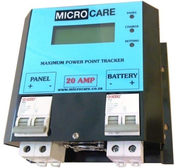
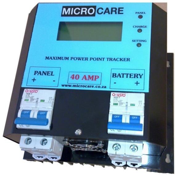
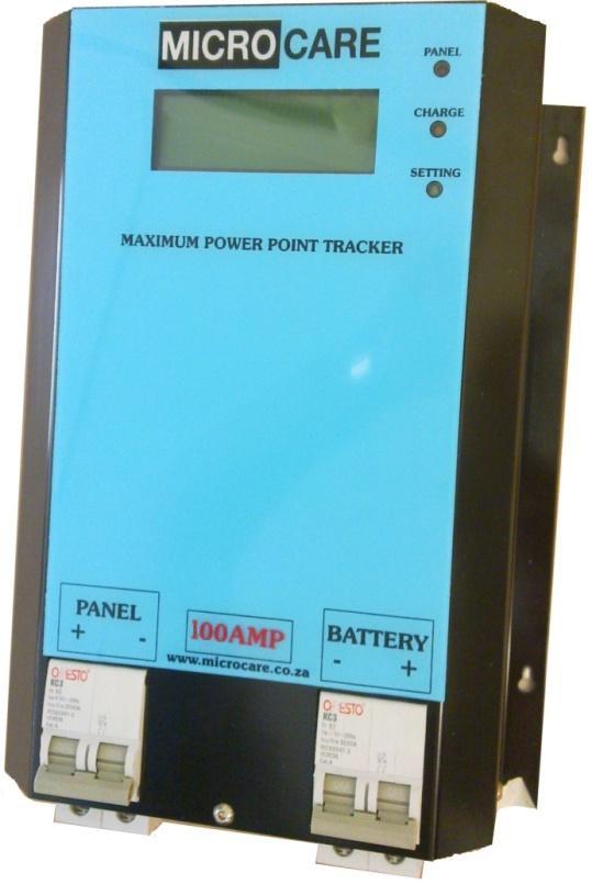
3 2. INTORODUCTION 2.1 General Description The Microcare Maximum Power Point Tracker Charge Controller is designed to provide maximum power from the panels into the batteries. Using this system up to 30% more power can be extracted from the panels than using shunt or series pass PWM controllers. The Microcare MPPT is able to charge batteries of a lower voltage than the panel system. A Liquid Crystal Display shows the status of the system and the data logging information. The unit has various programmable charge regimes which automatically adjust the charge levels when first starting up or if the battery falls below the minimum voltage. The MPPT will read the battery voltage when first starting up and select whether it is a 12v, 24v, 36v, or 48 volt battery system. It will then read the panel voltage and find the optimum power point. The charging, battery values and charge modes are then adjusted. This series features a durable and continuous 24 hour operation. The compact and modular design makes installations easy and cost effective. It is a high quality product that offers the best price/performance ratio in the industry. 2.2 Key Features 1. 4 X 20 LCD Display 2. Optional Input and Output circuit breaker protection 3. RS232 and Ethernet connectivity. 4. Fully programmable Days logger 6. High efficiency design with greater than 96% conversion. 7. Low heat dissipation. 8. Variable Fan cooling. 9. Suitable for any battery set between 12 and 48 Volt with 12V increments. 10. Electronically limited charge current 20, 40, 60, 100 Amps (dependent on the MPPT type). 11. Maximum open circuit PV Array voltage 150 VOC (Open Circuit Voltage). 12. Manual or Auto Equalise selection. 13. Wall mounted. 2.3 Important Notices Read the instructions carefully before operating the MPPT. The unit must only be installed in a clean dry environment. The unit should only be opened by skilled personnel. 3

4 2.4 Recommended Array Sizes: The following should be used as a guide to the maximum array size that can be connected to the MPPT. The current limits to the specified level of the MPPT model so any array larger than these will simply waste power: Recommended Photovoltaic Array Sizes in Watts Battery Set 20 Amp MPPT 40 Amp MPPT 60 Amp MPPT 100 Amp MPPT 12V 250W 500W 750W 1300W 24V 500W 1000W 1500W 2500W 36V 750W 1500W 2200W 3600W 48V 1000W 2000W 3000W 5000W 2.5 LCD MPPT Description: LCD Display: This indicates the MPPT s operation including Panel voltage, charge condition, charge amps, battery voltage and output power. 2. The <DATA>and<CHARGE> buttons are used to access the different menus and displays. 3. The Red LED indicates panel power. 4. The Yellow LED indicates charging. 5. The Green LED indicates battery in float condition. 6. The RJ12 connections at the top of the unit are for programming and RS232 signals. 7. Optional circuit breakers. 4
; it starts to charge the batteries at maximum efficiency in a BOOST mode which has")

5 2.6 MPPT Operation Description: This simple real world illustration (above) shows how an MPPT functions during the course of a day as well as a simple schematic (below). In the morning, as soon as the MPPT detects that the Panel Voltage is at a useable level (MPPT charge entry voltage); it starts to charge the batteries at maximum efficiency in a BOOST mode which has a nominal voltage of 14.5V per 12V battery bank. If however the batteries are detected to not be uniformly discharged, the MPPT will go into EQUALISE mode to restore battery bank balance before switching to BOOST mode as its primary charge mode. The MPPT maintains this mode until the batteries reach the boost voltage and the charge current decreases to a level below a nominal changeable level of 6Amps. The MPPT then steps down the charge voltage to a nominal voltage of 13.8V per 12V battery bank in FLOAT mode. The MPPT will attempt to maintain FLOAT mode for as long as the panel voltage is present. If no panel voltage is present, the MPPT goes into a sleep state until it detects a rise in panel voltage indicating a new day for charging. 5
6 3. MPPT SPECIFICATIONS N o m i n a l B a t t e r y V o l t ag e M u l t i - V o l t a g e ( A u t o m a t i c / M a n u a l s e l e c t i o n o f v o l t a g e / 2 4 / 3 6 / 4 8 V b a t t e r y s e t ) P V I n p ut V o l t ag e C h a r g e A l g o r i t h m E q u a l i ze V o l t a ge B o o s t V ol t a g e F l o a t V ol t a g e P o w e r C o n v e r si o n O u t p u t E f f i ci e n c y V o l t a ge S t e p d o w n C a p a b i l i t y S t a t u s d i s p l a y O p e n C i r c u i t A b s o l u t e M a x i m u m V DC 5 - s t a g e, 3 - l e v e l E q u a l i z e / B o o s t / F l o a t C h a r g e s 1 2 V t o 1 5 V p e r 1 2 V D C b a t t e r y p a c k f o r 1h ou r C h a r g e s t o V a n d s w i t c h e s w h e n c h a r g e c u r r e n t i s < 1 0 A m p s f o r 1 h o u r v p e r b a t t e r y D C / D C S w i t c h M o d e P e a k g r ea t e r t h a n 9 6 % c o n v er s i o n e f f i c i e n c y C a n c h a r g e a l o w e r v o l t a g e b a t t e r y fr o m a h i g h e r v o l t a g e P V a r r a y. 4 L i n e L C D S cr e e n w i t h B a c k l i g h t D a t a L o g g e r 2 4 h r A v e r a g e 3 1 d a y h i s t o r y B a t t e r y V o l t a g e C h a r g e m o d e - c h a r g e c u r r e n t (E q u a l i z e / B o o s t / F l o a t ) a n d C h a r g e c u r r e n t P a n e l V o l t a g e O u t p u t P o w e r S t a t e o f c h a r g e o f b a t t er y P o w e r C o n su m p t i on E n v i r o n m e nt a l R a t i n g L e s s t h a n 1 W a t t C P r o t e c t i o n S y s t e m L i g h t n i n g P r o t e c t i o n R e v e r s e p o l a r i t y P a n e l / B a t t e r y W a r r a n t y 36 m o n t h s Recommended Circuit Breaker sizes: MPPT Type Input Amp Output Amp 20 Amp 20A 25A 40 Amp 40A 50A 60 Amp 63A 63A 100 Amp 100A 125A 6

7 4. MPPT SYSTEM INSTALLATION 4.1 MPPT Installation Instructions Do not place the MPPT on a rugged or inclined surface. The MPPT must be mounted in a vertical position against a solid wall. Do not install the MPPT near water or in damp environments. Do not install the MPPT where it would be exposed to direct sunlight or near heat. Do not install the MPPT on a wooden surface. Only install the MPPT on flat concrete, stone or metal surfaces. Do not block off the aluminium heat sink and don t leave objects on top of the MPPT. Do not expose the MPPT to corrosive battery gases. MPPT operating environment temperature should not exceed: 0 C - 40 C. Ensure that connecting cables are of adequate thickness. Consult the reference table for recommended thicknesses in Cable Connections. Refer to the cable design sheet for correct PV cable thickness. 150mm Airflow 4x ANSI B18.6.5M - M6x1 x 20 Cross Recessed Pan Head Self Tapping Screws 143mm 40 Amp LCD MPPT Installation Diagram 204mm 150mm 7
8 MPPT Mounting Hole Dimensions Height Width 20 Amp LCD MPPT 143mm 204mm 40 Amp LCD MPPT 143mm 204mm 60 Amp LCD MPPT 227mm 204mm 100 Amp LCD MPPT 278mm 204mm 4.2 MPPT Setup Diagrams A simple PV system setup is illustrated with 48V DC Battery Set. This setup may be extended to suit the needs of the user. 150V is the maximum voltage the MPPT may accept, therefore, PV arrays may not have a voltage greater than 150V else the MPPT will be damaged. Battery Sets may not exceed a voltage of 48V. Ensure that the current strength leading into the MPPT from the PV Array does not exceed that of the maximum allowed by the specific MPPT model that is installed. 8
9 A complex PV-MPPT setup can have arrayed PV and Battery Sets all connected in parallel. The voltage of the PV array may not exceed 150V and depending on the MPPT model, a specified current strength. The Battery Set array is however unlimited in size although an increase in Batter Set array length will increase the amount of time needed to fully charge the batteries. This complex setup diagram of a PV-MPPT System illustrates two 120V DC PV Arrays connected in parallel and two 48V DC Battery Sets connected in parallel. 9
10 5. SAFETY INSTRUCTION 1. Route cable so that no one can step on them. 2. Batteries may cause electric shock and have a high short-circuit current. Please take the precautionary measures specified below and any other measures necessary when working with batteries. Remove wristwatches, rings and other metal objects. Use only tools with insulated grips and handles. 6. CABLE CONNECTIONS The PV (Photo Voltaic) panels should always be connected in the highest voltage configuration. The advantage of this is that panel current will always be at its minimum so that thinner connecting wires may be used which reduces voltage drops with loading and improves cost efficiency. The cable length from the batteries to the MPPT should not exceed 3m. The cable lengths connecting the PV panels to the MPPT should not exceed 30m. As an example, if there are two 40 volt panels rated at 5 amps each and they are connected in parallel, then the output voltage would be 40 volts at 10 amps. If they were connected in series the output would be 80 volts at 5 amps. In both cases the power would be the same but in the parallel configuration a thicker power cable must be used to reduce the volt drop from the array to the MPPT as well as from the MPPT the batteries. Cable thicknesses listed are recommended thicknesses that have voltage drops accounted for up to a distance of 3m for connecting the MPPT and the batteries together and the bottom table lists recommender cable thicknesses for cables connecting the MPPT to the panels up to a distance of 30m. Recommended Connecting Cables up to 3m from MPPT to batteries (Single Stranded Copper Specifications) MPPT Type Cable Core Area Overall Cable Diameter 20 Amp 6mm²-10mm² 5.4mm-6.3mm 40 Amp 10mm²-16mm² 6.3mm-7.5mm 60 Amp 20mm²-30mm² 8mm-9.5mm 100 Amp 40mm²-55mm² 10mm-13mm Recommended Connecting Cables up to 30m from MPPT to PV panels (Single Stranded Copper Specifications) MPPT Type Cable Core Area Cable Core Diameter 20 Amp 3mm²-4mm² 1.8mm-2.2mm 40 Amp 6.8mm²-9mm² 2.8mm-3.2mm 60 Amp 16mm²-21mm² 4.4mm-5mm 100 Amp 25mm²-32mm² 6mm-6.8mm 10
11 7. MPPT LCD OPERATION 7.1 Check Prior to Start Up 1. Ensure the MPPT is mounted vertically. 2. Check input output cables are secured. 3. Check the polarity of the panel and battery and they are correct. 4. Check if the Panel Voltage meets the MPPT rating required 7.2 Basic LCD Operation Procedure Please follow the instructions below for basic MPPT operation. 1. Turn ON the battery circuit breaker. The following screen should appear. S u p p l i e d b y S u p p l i e r D e t a i l s S u p p l i e r T e l N u m b e r S e r i a l N o = M C * * * * * This shows the name of the supplier, contact number and serial number. The screen will then change to:... S t a r t u p... C h e c k i n g B a t t e r i e s 4 8 v o l t s y s t e m This shows the unit automatically measuring the batteries and displaying the result. Should the battery voltage shown be incorrect it is possible to force the MPPT to accept a new battery value. 11
12 After checking, the screen will show: M I C R O C A R E M P P T 2 0 A m p P a n e l i s L O W... M P P T s l e e p i n g... B a t t e r y 7 0 % v This shows the capacity of the MPPT in amps, that there is NO power from the panel and that the STATE OF CHARGE of the battery is estimated to be 70%. After 10 minutes it will go into sleep mode and turn off the LCD screen. This may be reactivated by pushing any button. To review the displays again push the <CHARGE> button. Note: The state of charge of the batteries is only estimation to the state of charge of the battery bank. The panels must be switched off and the batteries must not have any load connected to them. Batteries should then be left in this state for at least a half an hour before reading battery charge levels to make decisions the estimation. The longer the batteries are left, the more accurate the estimation will be. If those steps are not followed, the battery state of charge reading can NOT be considered accurate. 2. Turn ON the Panel Circuit Breaker. The following screen should appear: T R A C K I N G M A X I M U M P O W E R P O I N T V p o w e r p o i n t... x x x V This shows the MPPT measuring the open circuit panel voltage and calculating the initial power point voltage. 12
13 The screen then changes to: BATTERY...= 12.0 V BOOST at...= 10.0 A PANEL...= 24.0 V OUTPUT POWER...= 120.0V This is the screen that will normally be displayed showing the system operating correctly. There are other details that will appear on the screen that will assist the user to read at what point the MPPT and batteries are: BATTERY...* = 13.8 V FLOAT AT... = 1.0 A PANEL... = 24.0 V OUTPUT POWER... = W The * flashing next to the batteries indicates that the MPPT is in FLOAT mode and the batteries are full. BATTERY... = 12.5V EQUALISE AT...! = 10.0A PANEL... = 24.0V OUTPUT POWER... = 125.0V The! sign next to the EQUALISE AT line indicates that the batteries are being charged in the Equalise mode and the batteries have not reached the equalise voltage, for every 12volt in the battery pack, system this would be 15 volts. 13
14 Once the batteries have reached the EQUALISE VOLTAGE then the display will change to: B A T T E R Y.... * = V E Q U A L I S E a t. = A P A N E L = V O U T P U T P O W E R = W This shows that the battery is at the EQUALISE Voltage, and that the MPPT is in the 1 hour bulk charge mode. When this is complete the charger switches to the BOOST mode and will hold the voltage at the programmable value say 14.5 until the charge current has fallen below the programmable BOOST amps, say 5.0 amps. B A T T E R Y.... * = V B O O S T a t.... = 5. 0 A P A N E L = V O U T P U T P O W E R = W When the charge current falls below the programmed value of say 5.0 amps, the screen will then change to: BATTERY...* = 13.8 V FLOAT at...= 1.0 A PANEL...= 28.0 V OUTPUT POWER...= 13.8 W This shows that the battery is in FLOAT mode and is indicated by the flashing * at the end of the BATTERY line. 14
15 7.3 Checking MPPT Firmware To determine the MPPT s firmware, make sure the LCD display is at the main screen: M I C R O C A R E M P P T 2 0 A m p P a n e l i s L O W... M P P T s l e e p i n g... B a t t e r y 7 0 % v or BATTERY...= 12.0 V BOOST at...= 10.0 A PANEL...= 24.0 V OUTPUT POWER...= 120.0V Now hold in the <CHARGE> button for 3 seconds and the following screen will appear for 2 seconds and then automatically revert to the main screen: F I R M W A R E V D O C S A N D S U P P O R T a t w w w. m i c r o c a r e. c o. z a Check the Microcare s website for the latest firmware available for your specific MPPT. To request a firmware upgrade for the MPPT, visit Microcare at and contact them via the online . 15
16 8. DATA LOGGING OPERATION By pushing the DATA button the following screen will appear: Day : H o u r : M i n 365 : 2 4 : 6 0 Tot : K w / H 2 4 H r : K w / H This shows the energy accumulated since the charger started. The 24Hr is the daily average for the no of days shown. Should you wish to CLEAR the DATA then hold the <CHARGE> button in for 6 seconds and the values will reset to 0 To view the next 8 days of DATA LOGGING push the <DATA> button and the screen will change to: 0 : : : : : : : : Day 0 shows the power accumulated for the current day. Up to 31 days of data is stored and may be viewed by pushing the <DATA> button. To clear the screen, hold in the <CHARGE> button in for 10 seconds or until the data has been cleared. To return to the main screen, the <DATA> button must be pressed until the end of the Data Log Menu has been reached. Alternatively, the MPPT will automatically revert to the normal charge display after 1minute. If a Battery Temperature and Battery Voltage Sensor is connected to the MPPT, the <DATA>button needs to be repeatedly pressed to return to the main screen. 16
17 9. PROGRAMMABLE OPERATION To enter the programming mode the panel circuit breaker must be turned OFF and the MPPT must be in the SLEEP MODE. Hold in the <CHARGE> button for 6 seconds and the following screen will appear: 9.1 Float Voltage: F L O A T C H A R G E V O L T A G E P E R B A T P A C K = v p r e s s C H R G t o s a v e To change the battery pack FLOAT VOLTAGE push the <DATA> button and the voltage can be changed from 13.2 to 14.5 volts with 0.1 volt increments. F L O A T C H A R G E V O L T A G E P E R B A T P A C K = v p r e s s C H R G t o s a v e Press <CHARGE> button to save the changed voltage. The screen will now change to: 9.2 Boost Voltage: B O O S T V O L T AGE P E R B A T P A C K = v p r e s s C H R G t o s a v e The Boost voltage can be changed between 13.5 and 16.0 volts. Press <CHARGE> to save. The screen will now change to: 17
18 9.3 Boost to Float Voltage: B O O S T T O F L T C H A N G E I N T E R V A L S C A N = 3 0 m n p r e s s C H R G t o s a v e This screen changes the time that the BOOST mode takes to switch to FLOAT mode once the batteries have reached the BOOST voltage level. The time can be 30minutes 1 hour 2 hours. Press <CHARGE> to save. The screen will then change to: B O O S T T O F L T C H A N G E I F C H A R G E < 6 a m p s p r e s s C H R G t o s a v e This changes the charge current at which the BOOST mode after timing out changes to FLOAT. This can be amps or Disabled. Press <CHARGE> to save. The screen will then change to: 9.4 Equalise Voltage: E Q U A L I S E C H A R G E M O D E A U T O E N A B L E D p r e s s C H R G t o s a v e In this mode the Regulator will automatically go into EQUALISE mode if the battery pack voltage falls below 10.8 volts. This enables or disables the EQUALISE Charge mode. The screen will now change to: 18
19 9.5 Battery Set Voltage: B A T T E R Y P A C K S E L E C T A U T O S E L E C T p r e s s C H R G t o s a v e This allows the user to leave the battery system selection to the MPPT or the selection can be PRESET. Pushing the <CHARGE> button will change the battery selection from AUTO to 6 cells 12 volts through to 24 cell 48 volt battery pack. The screen will now change to: 9.6 Charge Limit: C h a r g e L I M I T I = 9 5 % p r e s s C H R G t o s a v e This allows the user to limit the MPPT current. 100 % will be 20 amps or if the limit must be 18 amps then set the % to 90 % for a 20Amp MPPT as an example. This can be extended to any LCD MPPT type accordingly. 9.7 External Connections: Please refer to Section 10 on External Connections. 9.8 Change Time Settings: SET H O U R O F T H E D A Y = 1 4 : 4 p r e s s C H R G t o s a v e 19
20 This allows the user to change the time settings of the MPPT. The Hour of the day is changed in this screen through a 24hour time format with 1 hour increments. By pressing the <DATA> button, the display wills then change to change the minute s settings of the MPPT: S E T H O U R O F T H E D A Y = 1 4 : 4 p r e s s C H R G t o s a v e In this screen, the clock s minutes are adjusted in a similar fashion to that of the hour settings. Pressing the <DATA> button again will exit the settings menu and the MPPT will then reset itself with all adjusted settings loaded and normal MPPT operation will continue as soon as the PANEL breaker is reset. Note: Time settings do not affect any MPPT operations and are purely for user convenience. Time settings are lost when the batteries are disconnected from the MPPT. 10. EXTERNAL CONNECTIONS This allows the user to program the external output to operate the RELAY INTERFACE. This is plugged into the RJ12 port. E X T E R N A L O U T P U T I S A U N U S E D O U T P U T N / C p r e s s C H A R G E t o s a v e Pushing the <CHARGE> button will change the external output from being an UNUSED output to a: SOLAR ASSIST SIGNAL DAY NIGHT SIGNAL LOAD SHED SIGNAL (also known as a Low Battery Disconnect) SOLAR ASSIST SIGNAL V2 SOLAR AST UPS CNTR1 WIND TURBINE BRAKE 20
21 Note: The external output is only to be used with MICROCARE MPPT CHARGER accessories. Finally: Pressing the <CHARGE> button twice (pressing it once will display the time settings) will save the changes made to the MPPT. The MPPT will then reset itself and normal operation will continue as soon as the user resets the PANEL breaker The SOLAR ASSIST SIGNAL switches the relay for 10 seconds when the regulator switches from BOOST to FLOAT If DAY NIGHT SIGNAL mode is selected, it switches the relay when the panel power is LOW and stays ON until the panel reconnects If LOAD SHED DISCONNECT is selected (by pressing <CHARGE>to save) E X T E R N A L O U T P U T I S A L O A D S H E D D I S C O N N E C T p r e s s C H A R G E t o s a v e The following screen will appear: L O A D D I S C O N N E C T I N = V P E R B A T P A C K p r e s s C H A R G E t o s a v e The user can program the Voltage at which the RELAY operates. This is between volts per pack and increments in steps of 0.1 volts. If the system is 48 volts, multiply the settings by 4. If this is complete then the LOAD SHED RECONNECT voltage can be programmed which can be between volts per pack: L O A D R E C O N N E C T I N = V P E R B A T P A C K p r e s s C H A R G E t o s a v e p r e s s D A T A 21 t o c h a n g e
22 10.4 The SOLAR ASSIST SIGNAL V2 switches the relay for 10 seconds when the battery voltage is limiting the current into the system. This is when the * is flashing next to the Battery display If SOLAR AST UPS CNTR1 is selected (by pressing <CHARGE> to save) E X T E R N A L O U T P U T I S A L O A D S H E D D I S C O N N E C T p r e s s C H A R G E t o s a v e The following screen will appear: L O A D D I S C O N N E C T I N = V P E R B A T P A C K p r e s s C H A R G E t o s a v e The user can program the Voltage at which the RELAY operates. This is between volts per pack, in 0.1 volt steps. If the system is 48 volts multiply the settings by 4. If this is complete then the LOAD RELAY RECONNECT voltage may be programmed which can be between volts per pack. L O A D R E C O N N E C T I N = V P E R B A T P A C K p r e s s C H A R G E t o s a v e 22
23 10.6 Wind Turbine Brake is not used in the solar MPPT 10.7 If the Battery Temperature and Battery Voltage Sensor is plugged into the RJ12 connector then the following screen will show: R E M O T E B V T C O N N E C T E D V O L T A G E M P P T = x x. x V B V = V A D J - x x. x V B T = C A D J + x x. x V This shows the battery temperature and voltage. Should there be a problem with the cable or a poor connection then the screen will flash ERROR. Voltage MPPT shows the battery voltage at the output of the MPPT. The BV shows the voltage at the battery terminals. The correction is shown as either +/-. The Battery Temperature (BT) is then shown with the ADJ compensation. If the Battery Voltage Temperature is disconnected, the MPPT will revert back to stand alone readings. 23
24 24
Acceleration, Velocity, Separate probe VIBRATION METER Model : VB-8202
 Acceleration, Velocity, Separate probe VIBRATION METER Model : VB-8202 Your purchase of this VIBRATION METER marks a step forward for you into the field of precision measurement. Although this METER is
Acceleration/Velocity/Displacement VIBRATION METER
 Acceleration/Velocity/Displacement VIBRATION METER Model : VB-8220 Your purchase of this VIBRATION METER marks a step forward for you into the field of precision measurement. Although this METER is a complex
Operating Instructions for Digital Manometer. Model: MAN-SD
 Operating Instructions for Digital Manometer Model: MAN-SD 1. Contents 1. Contents...2 2. Note...3 3. Instrument Inspection...3 4. Regulation Use...4 5. Operating Principle...4 6. Mechanical Connection...5
S Sapling INSTALLATION MANUAL FOR FIELD SELECTABLE ANALOG CLOCKS SAA SERIES SPECIFICATIONS. advanced time and control systems
 INSTALLATION MANUAL FOR FIELD SELECTABLE ANALOG CLOCKS SAA SERIES SPECIFICATIONS Time base: 60 Hz (3-wire system) Quartz (2-wire system) Power input: 85 135 VAC / 60 Hz 7 28 VAC / 60 Hz Current consumption:
Minute Impulse Clock Controller I01DN
 99b-mi USER S MANUAL Minute Impulse Clock Controller Mon Jun 01, 2009 12:00:00 PM DST HOLD ENTER KEY TO BEGIN CANCEL HR I01DN 97 West Street Medfield, MA 02052 U.S.A. (508) 359-4396 Pg. 2 of 20 TABLE OF
Nixie Clock Manuela Desktop. User Manual
 Nixie Clock Manuela Desktop User Manual May 2011 Safety Precautions Do not power on the clock when tubes are damaged or missing. Use the power supply that came with the clock, or use a power supply that's
Bright Advance Corporation
 USER INSTRUCTIONS TABLE OF CONTENTS INSTRUCTIONS FOR USE2 PREPARING TO USE THE SCALE2 DISPLAYS3 KEYBOARD FUNCTION4 OPERATION7 COUNTING14 DIFFERENT KEYBOARD TYPES21 INTERFACE31 POWER SOURCES40 1 INSTRUCTIONS
OPERATION MANUAL. 3 in 1, IR, Type K/J/R/E/T, Pt 100 ohm THERMOMETER. Model : TM-2000
 3 in 1, IR, Type K/J/R/E/T, Pt 100 ohm THERMOMETER Model : TM-2000 Your purchase of this THERMOMETER marks a step forward for you into the field of precision measurement. Although this THERMOMETER is a
SECTION 1 - WHAT IS A BTU METER? BTU's = Flow x ΔT Any ISTEC BTU Meter System consists of the following main components:
 SECTION 1 - WHAT IS A BTU METER? ISTEC BTU Meters measure energy usage by multiplying flow rate and temperature difference. As the water (or other liquid) passes through these lines, the multi-wing turbine
Assembly and Operation Manual. April 2016
 Assembly and Operation Manual April 2016 Table of Contents What is in the OurWeather Box? 3 Step by Step Assembly 13 Building the Weather Sensors 18 Testing the OurWeather Weather Station 28 Power Up OurWeather
Structure Monitoring Technology. Features. Ordering Information. Trigger Tape. A2 Pulse Counter (Optional) Solar Radiation Sensor
 Solar Radiation Sensor") Rain detection sensor General Description Driving rain and its effective management are critical factors in determining the durability of building enclosures. An accurate measurement of driving rain can
Rain detection sensor General Description Driving rain and its effective management are critical factors in determining the durability of building enclosures. An accurate measurement of driving rain can
INFRARED THERMOMETER Model : TM-959
 LED target light, Emissivity adjustment INFRARED THERMOMETER Model : TM-959 Your purchase of this I N F R A R E D THERMOMETER marks a step forward for you into the field of precision measurement. Although
SC125MS. Data Sheet and Instruction Manual. ! Warning! Salem Controls Inc. Stepper Motor Driver. Last Updated 12/14/2004
 SC125MS Stepper Motor Driver Salem Controls Inc. Last Updated 12/14/2004! Warning! Stepper motors and drivers use high current and voltages capable of causing severe injury. Do not operate this product
A clock designed in close consultation with people living with Dementia.
 1. Product Name Day Clock 2. Product Code 55787 3. Colour As shown 4. Brief Description A clock designed in close consultation with people living with Dementia. 5. Contents 1 x Day Clock 6. Snoezelen Stimulations
ISOCON-6. 24V AC or DC POWERED ISOLATING SIGNAL CONVERTER
 ISOCON-6 24V AC or DC POWERED ISOLATING SIGNAL CONVERTER Whilst every effort has been taken to ensure the accuracy of this document, we accept no responsibility for damage, injury, loss or expense resulting
MODE button MAX/MIN button CHANNEL button / C/ F / RCC button SNOOZE / LIGHT button Battery compartment A/C in-jack 3. 4.
 KL4912 Desktop weather station Instruction Manual Introduction This weather station comes with backlight, indoor and outdoor temperature & humidity display, and alarm clock with calendar. Fig. 1 Front
473-SHX Dew Point Mirror
 Humidity and Temperature Reference Hygrometer For Temperature up to 125 C Precise and stable chilled mirror dew point mirror technology High temperature optical components High temperature sample fan Cable
WeatherHub2 Quick Start Guide
 WeatherHub2 Quick Start Guide Table of Contents 1 Introduction... 1 2 Packing List... 1 3 Connections... 1 4 IP Addressing... 2 5 Browser Access... 3 6 System Info... 3 7 Weather Station Settings... 4
iweathar EDGE V Installation Guide Copyright 2012 iweathar. All rights reserved.
 iweathar EDGE V Installation Guide Copyright 2012 iweathar. All rights reserved. Table of contents: 1 Introduction...3 2 Station Components...4 3 STATION INSTALLATION PROCEDURE...5 4 Specifications...11
ph electrode Instruction Manual For use with the RAH-210 & RPH-250
 ph electrode Instruction Manual For use with the RAH-210 & RPH-250 The information in this manual was current at the time of printing. The most current versions of all Hydro Instruments manuals can be
ISOCON-3 MAINS POWERED ISOLATING SIGNAL CONVERTER
 ISOCON-3 MAINS POWERED ISOLATING SIGNAL CONVERTER CAUTION: This equipment is designed for connection to mains voltages and must be used in accordance with this guide. If it is not, the safety protection
473 Dew Point Hygrometer
 gh Performance Chilled Hygrometer With Cable Mounted Measuring Heads ghly precise chilled mirror dew point technology Cable mounted dew point and temperature measurement Aspirated and direct insertion
MAGMA NOTE! 21+ USER MANUAL
 21+ MAGMA USER MANUAL NOTE! Please do not put this product away or leave it for extended periods of time with low charge because if the battery falls below 2% then it will no longer accept a charge. Thank
WLDS-20 Mk2 MAJOR WATER LEAK DETECTION SYSTEM INSTALLATION & COMMISSIONING
 WLDS-20 Mk2 MAJOR WATER LEAK DETECTION SYSTEM INSTALLATION & COMMISSIONING DESCRIPTION: An electronic control panel used in conjunction with two pulse meters (water meters with pulse output proportional
HMS-5000 Manual. Product Name: HMS-5000 Hall Effect Measurement System with variable temperature from 80K to 350K. - Manual version: ver 5.
 HMS-5000 Manual Product Name: HMS-5000 Hall Effect Measurement System with variable temperature from 80K to 350K - Manual version: ver 5.01- www.ecopia21.co.kr - Table of contents - 1. Hardware Installation
DIGITAL THERMOMETER OPERATOR S MANUAL
 DIGITAL THERMOMETER OPERATOR S MANUAL 51 206-3722 52 206-3738 DIGITAL THERMOMETER OPERATOR'S MANUAL RS 51 206-3722 RS 52 206-3738 1 2 INTRODUCTION 1-1 Unpacking and Inspection Upon removing your new Digital
473 Dew Point Hygrometer
 High Performance Chilled Mirror Hygrometer With Cable Mounted Measuring Heads Highly precise chilled mirror dew point technology Cable mounted dew point and temperature measurement Aspirated and direct
VIBRATION METER Acceleration & Velocity Model : VB-8201HA
 VIBRATION METER Acceleration & Velocity Model : VB-8201HA TABLE OF CONTENTS 1. FEATURES... 1 2. SPECIFICATIONS...2 3. FRONT PANEL DESCRIPTION...4 3-1 Display...4 3-2 BNC socket of meter...4 3-3 RMS/PEAK
HMS-5000 Manual. Product Name: HMS-5000 Hall Effect Measurement System with variable temperature from 80K to 350K. - Manual version: ver 5.
 HMS-5000 Manual Product Name: HMS-5000 Hall Effect Measurement System with variable temperature from 80K to 350K - Manual version: ver 5.01- www.ecopia21.co.kr - Table of contents - 1. Hardware Installation
Quick Start Guide. The ieq45 GoTo German Equatorial Mount # 8000C
 Quick Start Guide The ieq45 GoTo German Equatorial Mount # 8000C PACKAGE CONTENTS Telescope Mount (with built-in GPS) 3.5 Vixen type dovetail saddle (installed on the mount) 8 Losmandy-D type dovetail
Dual laser + type K thermometer INFRARED THERMOMETER
 Dual laser + type K thermometer INFRARED THERMOMETER Model : ATE-2509 Your purchase of this INFRARED THERMOMETER marks a step forward for you into the field of precision measurement. Although this METER
Safety Precautions WARNING If critical situations that could lead to user s death or serious injury is assumed by mishandling of the product.
 Safety Precautions Observe the following notices to ensure personal safety or to prevent accidents. To ensure that you use this product correctly, read this User s Manual thoroughly before use. Make sure
PHY222 - Lab 7 RC Circuits: Charge Changing in Time Observing the way capacitors in RC circuits charge and discharge.
 PHY222 Lab 7 RC Circuits: Charge Changing in Time Observing the way capacitors in RC circuits charge and discharge. Print Your Name Print Your Partners' Names You will return this handout to the instructor
MODELS Number WW4.x For Europe & Others V 50HZ
 MODELS Number NA4.x For USA/Canada/Mexico 110-120V 60HZ MODELS Number WW4.x For Europe & Others 210-240V 50HZ Thank you for purchasing the Sunflex 24 Plus Daylight Controller, The most flexible and innovative
Request Ensure that this Instruction Manual is delivered to the end users and the maintenance manager.
 Request Ensure that this Instruction Manual is delivered to the end users and the maintenance manager. 1 -A - Introduction - Thank for your purchasing MITSUBISHI ELECTRIC MELPRO TM D Series Digital Protection
Today s Weather 24 Hour Forecaster
 1380 Today s Weather 24 Hour Forecaster Instruction Manual The Taylor 24 Hour Forecaster will provide you with actual current temperatures. Predict the weather conditions for the next 24 hours as well
Kingspan Smart-Lite Kite Luminaire
 Kingspan Smart-Lite Kite Luminaire The Kite High Bay products are designed to complement the ZEL (Zero Energy Lighting) initiative championed by Kingspan. The combination of pressure die-cast aluminium
FLT5A FLT5A. abc. abc. Thermometer User Guide. Thermometer User Guide. Internet:
 abc instruments international FLT5A Thermometer Land Instruments International Dronfield, S18 1DJ England Telephone: (1246) 417691 Facsimile: (1246) 41585 Email: infrared.sales@landinst.com Internet: www.landinst.com
AccuAligning TM Polar Scope for SmartEQ TM Portable German Equatorial GOTO Mount. Installation and User Manual. Product #3130
 AccuAligning TM Polar Scope for SmartEQ TM Portable German Equatorial GOTO Mount Installation and User Manual Product #3130 ioptron Corporation, 6E Gill Street, Woburn, MA 01801 www.ioptron.com ioptron
xlogic SuperRelay is a compact and expandable CPU replacing mini PLCs, multiple timers, relays and counters.
 SuperRelay S U P E R R E L A Y, T H E P E R F E C T A L T E R N A T I V E T O L O W C O S T P L C s A N D B A S I C R E L A Y S I N T H I S B R O C H U R E : ELC 18 Standard Models ELC 18 Economy Models
Operating instructions Magnetic-inductive flow sensor SM6004 SM7004 SM / / 2014
 Operating instructions Magnetic-inductive flow sensor SM6004 SM7004 SM8004 80003223 / 00 05 / 2014 Contents 1 Preliminary note...3 1.1 Symbols used...3 2 Safety instructions...4 3 Functions and features...5
AIR CONDITIONER (SPLIT TYPE) SERVICE MANUAL
 SERVICE MANUAL") AIR CONDITIONER (SPLIT TYPE) SERVICE MANUAL FILE No. A10-023-1 REVISION 1 : Mar.2012 Re-edit version.( file volume down) Contents have NOT been changed. Model name: RAS-M10PKVP-E RAS-M13PKVP-E RAS-M16PKVP-E
AIR CONDITIONER (SPLIT TYPE) SERVICE MANUAL FILE No. A10-023-1 REVISION 1 : Mar.2012 Re-edit version.( file volume down) Contents have NOT been changed. Model name: RAS-M10PKVP-E RAS-M13PKVP-E RAS-M16PKVP-E
INSTRUCTION MANUAL RS 51 & RS 52 DIGITAL THERMOMETER
 INSTRUCTION MANUAL RS 51 & RS 52 DIGITAL THERMOMETER EN FR IT DE RS 51 & RS 52 DIGITAL THERMOMETER INSTRUCTION MANUAL 2 INTRODUCTION 1-1 Unpacking and Inspection Upon removing your new Digital Thermometer
Minimum (-31) every 10 s -35 (-31)
 every 10 s -35 (-31)") Humidity, and Dew Point Data Logger with LCD ORDERING INFORMATION Standard Data Logger (Data Logger, Software on CD, Battery) Replacement Battery EL-USB-2-LCD BAT 3V6 1/2AA FEATURES 0 to 100 measurement
Humidity, and Dew Point Data Logger with LCD ORDERING INFORMATION Standard Data Logger (Data Logger, Software on CD, Battery) Replacement Battery EL-USB-2-LCD BAT 3V6 1/2AA FEATURES 0 to 100 measurement
O P E R A T I N G M A N U A L
 OPERATING MANUAL WeatherJack OPERATING MANUAL 1-800-645-1061 The baud rate is 2400 ( 8 bits, 1 stop bit, no parity. Flow control = none) To make sure the unit is on line, send an X. the machine will respond
FL ballasts Electronic fixed output. PC TC PRO sr 1/2x11 42 W PC PRO compact
 FL ballasts EL HE PC TC PRO sr 1/2x11 42 W PC PRO compact Product description CELMA Energy Efficiency Index A2 BAT / A2 T Nominal life-time up to 50,000 h (at ta 50 C with a failure rate max. 0.2 % per
PiCUS Calliper Version 3
 Technology PiCUS Calliper Version 3 Digital calliper for precise geometry detection argus electronic GmbH Erich-Schlesinger-Straße 49d 18059 Rostock Germany Tel.: +49 (0) 381/49 68 14 40 www.argus-electronic.de
VIBRATION METER. Instruction Manual.
 VIBRATION METER 840063 Instruction Manual CONTENTS Title Page I. Introduction... 2 II. Panel Description... 3 III. Operating Instructions A. General Measurement Procedures... 3~4 B. Peak... 5 C. Data Hold...
Emergency lighting units EM Inverter
 T T TC- TC-F DE TC- TC-SE TC-TE TC-DD Tc EM G, 0 0 V 0/0 Hz BASIC version Product description Emergency lighting supply unit for manual testing For linear and compact fluorescent lamps ow-profile casing
H i g h A m p e r a g e 2 5 t o A M P. T y p e I & I I I V e h i c l e P r o t e c t i o n. I P 6 7 W a t e r p r o o f
 H i g h A m p e r a g e 2 5 t o 3 0 0 A M P T y p e I & I I I V e h i c l e P r o t e c t i o n I P 6 7 W a t e r p r o o f I g n i t i o n - P r o t e c t e d S A E & A B Y C C o m p l i a n t L E D T
ATT 310 USER MANUAL
 34-994 ATT 30 USER MANUAL Model 30: DIP Switch Settings to Change Print Formats DIP SW DIP SW2 On On Com: Comment, Mo: Month, DOW: Day of Week Num: Sequential Number (see pg 0 of manual)
OPERATING MANUAL. EIB-Kombisensor AS 315 N
 EIB-Kombisensor AS 315 N OPERATING MANUAL EIB-Kombisensor AS 315 N 1 Contents Page 3 1. Description 4 1.1 Automated Operations 1.1.1 Sun System 1.1.2 Half-Light System 5 1.1.3 Wind System 1.1.4 Rain System
INSTRUCTION MANUAL Milwaukee Refractometer MA881 Refractometer for Invert Sugar Measurements
 www.milwaukeeinst.com INSTRUCTION MANUAL Milwaukee Refractometer MA881 Refractometer for Invert Sugar Measurements www.milwaukeeinst.com 1 Instruction Manual MA881 Refractometer for Invert Sugar Measurements
NorthStar Battery Company DCN: SES DCR: 1038-S07 Date: Page 1 of 12
 Battery Testing Using Conductance Technology for NSB Series Valve-Regulated Lead Acid Batteries Approved: Dr F.A.Fleming Date: 01-08-07 Page 1 of 12 Table of Contents Background-Principals behind conductance
ISSP User Guide CY3207ISSP. Revision C
 CY3207ISSP ISSP User Guide Revision C Cypress Semiconductor 198 Champion Court San Jose, CA 95134-1709 Phone (USA): 800.858.1810 Phone (Intnl): 408.943.2600 http://www.cypress.com Copyrights Copyrights
DIAGNOSTICS NO TOUCH FOREHEAD THERMOMETER
 DIAGNOSTICS NO TOUCH FOREHEAD THERMOMETER nu-beca NO TOUCH THERMOMETER : Thank you for purchasing the nu-beca No Touch Forehead Thermometer. Please read this instruction manual first so you can use this
Experiment C-15 Distillation - part 1
 1 Experiment C-15 Distillation - part 1 Objectives To learn about the three classical phases of matter, phase changes, and heating and cooling curves. To investigate the technique of distillation and to
Test Equipment Depot Washington Street Melrose, MA TestEquipmentDepot.com INSTRUCTION MANUAL. Milwaukee Refractometer
 Test Equipment Depot - 800.517.8431-99 Washington Street Melrose, MA 02176 TestEquipmentDepot.com INSTRUCTION MANUAL Milwaukee Refractometer MA871 Refractometer for Sucrose Measurements 1 Instruction Manual
VIBRATION TACHOMETER OPERATION MANUAL. 3 in 1. Model : VT Your purchase of this
 3 in 1 VIBRATION TACHOMETER Model : VT-8204 Your purchase of this VIBRATION TACHOMETER marks a step forward for you into the field of precision measurement. Although this VIBRATION TACHOMETER is a complex
Peltier Application Note
 Peltier Application Note Early 19th century scientists, Thomas Seebeck and Jean Peltier, first discovered the phenomena that are the basis for today s thermoelectric industry. Seebeck found that if you
Single pyro altimeter AltiUno SMT operating instructions
 Single pyro altimeter AltiUno SMT operating instructions Version date Author Comments 1.0 09/03/2014 Boris du Reau Initial version 1.1 11/03/2014 Boris du Reau Updated version 1.2 27/03/2014 Boris du Reau
Quick Reference. Daily Cleaning Procedures Pages 3-8 Stopping Conditions & Recovery Steps Pages 9-20
 Quick Reference for Daily Cleaning Procedures Pages 3-8 Stopping Conditions & Recovery Steps Pages 9-20 852 Feehanville Drive Mt. Prospect, IL 60056 Telephone: (847) 299-9550 Fax: (847) 759-3091 2009 CUMMINS-ALLISON
WS-9018U Wireless Weather Station. Instruction Manual
 WS-9018U Wireless Weather Station Instruction Manual Contents Page 1. Functions of the Weather Station....3 2. Safety notes...3 3. Product features....4 4. Getting started....4 5. Quick Set Up...5 6. Setting
Data Logger V2. Instruction Manual
 Data Logger V2 Instruction Manual Joe Holdsworth 7-29-2018 Contents Revision History... 2 Specifications... 3 Power Limits... 3 Data Rates... 3 Other Specifications... 3 Pin Outs... 4 AS218-35SN... 4 AS210-35SN...
Richter Optica. Instructions for Model: S850 Stereo Zoom Microscope
 Richter Optica info@richter-optica.com Instructions for Model: S850 Stereo Zoom Microscope Microscope Head Focus Knob Stage Clips Zoom Knob C-Mount Adapter Eyepiece Focusing Holder Focusing Holder Set
SUNLIKE DISPLAY. Model No: SC2004C GENERAL SPECIFICATION
 GENERAL SPECIFICATION ITEM Product No SC2004CSLB-XA-LB-G DESCRIPTION STN Gray Positive STN Yellow Green Positive STN Blue Negative LCD Type TN Negative TN Positive FSTN Negative White & Black FSTN Positive
E2T0 DVP
 29-5-26 5116868-E2T DVP-11363-1 ENGLISH Thank you for choosing Delta s DVP series PLC. DVP4TC-E2 temperature measurement module receives 4 points of external thermocouple temperature sensors (J-type, K-type,
Self-Testing Prevectron 2 Millenium Lightning Conductor Set-up and Installation Manual
 Self testing Prevectron 2 Millenium Lightning Conductor ENGLISH Self-Testing Prevectron 2 Millenium Lightning Conductor Set-up and Installation Manual S6.60T S4.50T S3.40T N.B. : Information and Specifications
SOTM LAB: P16 OHM S LAW I. TEACHER NOTES & GUIDELINES TITLE OF LAB: Ohm s Law DEVELOPERS OF LAB:
 SOTM LAB: P16 OHM S LAW I. TEACHER NOTES & GUIDELINES TITLE OF LAB: Ohm s Law DEVELOPERS OF LAB: John Lane, JD853@maristb.marist.edu Taylor Pancoast, JD573@maristb.marist.edu OVERVIEW OF LAB DESCRIPTION
рн PRO Controller The device is used to control and regulate ph level in hydroponic systems and water preparing units automatically USER MANUAL
 рн PRO Controller The device is used to control and regulate ph level in hydroponic systems and water preparing units automatically Complete Set ph PRO Controller - 1 pcs. ph electrode - 1 pcs. Calibration
Operation Manual Contents subject to change without notice
 318513 Operation Manual Contents subject to change without notice Version 1.0 Issue AA TABLE OF CONTENTS 1. INTRODUCTION and INSTALLATION... 1 General and Safety Information... 1 Specifications... 1 Contents...
A Rain Sensitive House Window Closes Automatically When Raining
 A Rain Sensitive House Window Closes Automatically When Raining House windows are sometimes opened when it rains and no body around to close them allowing rain going in side and damage the house. Information
Capacitor investigations
 Sensors: Loggers: Voltage Any EASYSENSE Capacitor investigations Logging time: EasyLog (20 s) Teacher s notes 01 Time constant for a capacitor - resistor circuit Theory The charging and discharging of
Installation Manual. Installation manual for PerfectEnergy Solar Modules. Content
 Installation manual for PerfectEnergy Solar Modules Content 1. Preface 2. Technical data/general 3. Safety instructions 4. Mechanical Installation 5. Electrical installation 6. Grounding 7. Maintenance
 Humidity, and Dew Point Data Logger with LCD ORDERING INFORMATION Standard Data Logger (Data Logger, Software on CD, Battery) Replacement Battery EL-USB-2-LCD BAT 3V6 1/2AA FEATURES 0 to 100 measurement
Chemistry MultiMeasure Sensor PS-2170
 ä 5 Instruction Manual 012-09523A Chemistry MultiMeasure Sensor PS-2170 ph/ise/orp PRESSURE CHEMISTRY TEMPERATURE SENSOR VOLTAGE 1 2 3 4 PS-2170 5 6 7 cc 8 10 15 20 25 30 35 40 45 50 55 60 Included Equipment
State Feedback Control of a DC-DC Converter for MPPT of a Solar PV Module
 State Feedback Control of a DC-DC Converter for MPPT of a Solar PV Module Eric Torres 1 Abstract The optimum solar PV module voltage is not constant. It varies with ambient conditions. Hense, it is advantageous
Product manual. Mylos KNX Shutter actuator 2CSY1104C/S
 Product manual Mylos KNX Shutter actuator 2CSY1104C/S Contents Contents 1 Technical features... 3 1.1 Technical data... 3 1.2 Connection diagram... 4 2 Commissioning... 5 2.1 Parameters... 5 2.1.1 General...
Module 1 Units 3,4,5
 Module 1 Units 3,4,5 1. What is matter? Anything that occupies space or has mass 2. What are the two general categories of substances? Elements and compounds 3. How many naturally occurring elements are
MN-ISO-2000FN-E. ISO-2000FN COATING THICKNESS GAGE OPERATION MANUAL
 MN-ISO-2000FN-E www.insize.com ISO-2000FN COATING THICKNESS GAGE OPERATION MANUAL V0 Place the probe on the zero plate and wait until beep. Lift the probe for minimal 5 cm off the zero plate and wait
Latest generation testo air velocity & IAQ probes with cable handle. Instruction manual
 Latest generation testo air velocity & IAQ probes with cable handle Instruction manual Contents Contents 1 About this document... 5 2 Safety and disposal... 5 3 System description... 6 4 Description of
SPECIFICATION SHEET : FHS2-UNV-36L
 SPECIFICATION SHEET : FHS2-UNV-36L This Is An Original Product From Fulham Co., Inc Description : For Back-up Lighting This driver will operate constant current LED arrays with a working voltage between
Request Ensure that this Instruction Manual is delivered to the end users and the maintenance manager.
 Request Ensure that this Instruction Manual is delivered to the end users and the maintenance manager. 1 -C - Safety section - This Safety section should be read before starting any work on the relay.
WS-7047TWC Wireless 433 MHz Weather Station With Rainfall and Temperature. Instruction Manual
 WS-7047TWC Wireless 433 MHz Weather Station With Rainfall and Temperature Instruction Manual TABLE OF CONTENTS Topic Page Inventory of Contents 2 Additional Equipment 2 Quick Setup 3 Detailed Setup Guide
SPECIFICATION SHEET : FHS2-UNV-36L
 SPECIFICATION SHEET : FHS2-UNV-36L This Is An Original Product From Fulham Co., Inc Description : Emergency LED Driver For Back-up Lighting This driver will operate constant current LED arrays with a working
Flexitest Switch Assemblies Type FT-19R and FT-19RX Supersedes DB March 2008
 Flexitest Switch Assemblies Type FT-19R and FT-19RX Supersedes DB41-078 March 2008 FT-19R and FT-19RX FT-19R 3RU with Individual Clear Covers APPLICATION FEATURES The type FT-19R (standard length) and
3B SCIENTIFIC PHYSICS
 3B SCIENTIFIC PHYSICS 30 V, 50/60 Hz: 1018884 / U07001-30 115 V, 50/60 Hz: 101888 / U07001-115 Millikan s Apparatus Instruction sheet 07/16 UD/ALF Safety instructions Millikan s apparatus conforms to the
Rain Watch TM Set up Manual. IC System with Rain Bird IC CONNECT
 Rain Watch TM Set up Manual IC System with Rain Bird IC CONNECT December 2018 Table of Contents Required materials to configure Rain Watch TM... 3 Installation... 4 Location... 4 Field Installation...
technical bulletin Installation Instructions: Wall-Mount Dewpoint Probe ( )
") Installation Instructions: Wall-Mount Dewpoint Probe (809-2011) The HMW90 Wall-Mount Dewpoint Probe (P/N 809-2011) HMW90 measures dewpoint for indoor applications such as anti-sweat heater control and
Installation Instructions: Wall-Mount Dewpoint Probe (809-2011) The HMW90 Wall-Mount Dewpoint Probe (P/N 809-2011) HMW90 measures dewpoint for indoor applications such as anti-sweat heater control and
Zone Clocks. Installation Manual. Version Number 2.0 Current as of July 20, The Sapling Company, Inc. 670 Louis Drive Warminster, PA USA
 Installation Manual Zone Clocks Version Number 2.0 Current as of July 20, 2018 The Sapling Company, Inc. 670 Louis Drive Warminster, PA 18974 USA (+1) 215.322.6063 P. (+1) 215.322.8498 F. Zone Clocks Table
Resistivity and Temperature Coefficients (at 20 C)
") Homework # 4 Resistivity and Temperature Coefficients (at 0 C) Substance Resistivity, Temperature ( m) Coefficient, (C ) - Conductors Silver.59 x 0-0.006 Copper.6 x 0-0.006 Aluminum.65 x 0-0.0049 Tungsten
Homework # 4 Resistivity and Temperature Coefficients (at 0 C) Substance Resistivity, Temperature ( m) Coefficient, (C ) - Conductors Silver.59 x 0-0.006 Copper.6 x 0-0.006 Aluminum.65 x 0-0.0049 Tungsten
PAA-ANALYZERS PRINCIPLE OF OPERATION
 PAA-ANALYZERS PRINCIPLE OF OPERATION The PAA process analyzer comprises a control unit and an analyzing section which includes the reaction chamber and measuring cell, reagent pumps and associated valves
INSTRUCTION MANUAL FOR MM10 Relay
 INSTRUCTION MANUAL FOR MM10 Relay Motor Protection Relay Front Panel Overview V1 250614 MM10 Motor Protection Relay a I L1 b I L2 I L3 c h i d e I L1 Figure 1: Front panel overview f g I L2 a Run LED b
1. Electrostatic Lab [1]
![1. Electrostatic Lab [1]](/thumbs/72/67418586.jpg "1. Electrostatic Lab [1]") 1. Electrostatic Lab [1] Purpose: To determine the charge and charge distribution on insulators charged by the triboelectric effects and conductors charged by an Electrostatic Voltage Source. Equipment:
1. Electrostatic Lab [1] Purpose: To determine the charge and charge distribution on insulators charged by the triboelectric effects and conductors charged by an Electrostatic Voltage Source. Equipment:
U.S. Atomic Clock & Weather Station. Instruction Manual
 U.S. Atomic Clock & Weather Station Instruction Manual Table of Contents What is Atomic Radio Control?... 2 Parts Diagram... 3 Batteries... 4 Setting the Atomic Time and Date... 4 Setting the Clock...
SAFYR7 KAPPABRIDGE CONTROL SOFTWARE. User Manual
 SAFYR7 KAPPABRIDGE CONTROL SOFTWARE User Manual Version 1.1 April 2018 Contents Contents 1 Introduction 1 2 Getting Started 3 2.1 System Requirements................................. 3 2.2 Program Installation..................................
GS110. IR Thermal Imaging System for Low-Emissivity Glass with Automatic Emissivity Correction. Manual Addendum
 GS110 IR Thermal Imaging System for Low-Emissivity Glass with Automatic Emissivity Correction Manual Addendum Rev. B 10/2006 1 Safety Instructions All notices regarding safety and acceptable operation
QUANTUM CONCEPT. Swimming User s Manual
 QUANTUM CONCEPT Swimming User s Manual 480.508.0 Version.4 Edition July 05 Documentation Updates Swiss Timing Ltd. reserves the right to make improvements in the products described in this documentation
Circular Motion and Centripetal Force
 [For International Campus Lab ONLY] Objective Measure the centripetal force with the radius, mass, and speed of a particle in uniform circular motion. Theory ----------------------------- Reference --------------------------
LAB 3: Capacitors & RC Circuits
 LAB 3: Capacitors & C Circuits Name: Circuits Experiment Board Wire leads Capacitors, esistors EQUIPMENT NEEDED: Two D-cell Batteries Multimeter Logger Pro Software, ULI Purpose The purpose of this lab