Radio Interference Suppression Capacitors and Filters
|
|
|
- Sabina Horn
- 6 years ago
- Views:
Transcription
1 Radio Interference Suppression Capacirs and Filters
2
3 Index General information on Iskra Capacirs for Radio Interference Suppression Components General information 2 Radio Interference Suppression Components Page Rated voltage Class, 300 V AC X2 metallized polypropylene film capacir KNBx, 300 V AC X2 metallized polypropylene film capacir 2 KNR3x X2 metallized polypropylene film capacir with resisr (RC unit) 2 KNB22x 2 V AC, 300 V AC Y2 metallized polypropylene film capacir KNB23x 0 V AC Y metallized polypropylene film capacir 2 KNB4x 0 V AC X metallized polypropylene film capacir 3 KNBx 30 V AC X metallized polypropylene film capacir 33 KNB73x X2Y2 metallized polypropylene film capacir 3 KPB23xx X impregnated paper capacir 3 KPR23xx X impregnated paper capacir with resisir (RC unit) 37 KPB3xx Y2 impregnated paper capacir 38 KPB70xx 2 V AC, XY2 impregnated paper capacir 3 KNB7077 XY2 impregnated paper capacir 40 KPB73xx 2 V AC, XY2 impregnated paper capacir 4 KPB732 XY2 impregnated paper capacir 43 KPB734 XY2 impregnated paper capacir KPB742 XY2 impregnated paper capacir 4 KNB742 XY2 metallized polypropylene film capacir KPB83xx XY2 impregnated paper capacir 47 KP3008 XY2 impregnated paper capacir (C filter) 48 KP300 XY2 impregnated paper capacir (C filter) KP3023 XY2 impregnated paper capacir (C filter) 2 KP3024 XY2 impregnated paper capacir (C filter) 4 KP38 XY2 impregnated paper capacir (C filter) KP323 2 V AC, XY2 impregnated paper capacir (C filter) KP324 2 V AC, XY2 impregnated paper capacir (C filter) 2 KP V AC, XY2 impregnated paper capacir (C filter) KN324 2 V AC XY2 metallized polypropylene film capacir (C filter) Type KNB3x Construction of capacirs
4 General Information Origin and spreading of interference There are two main sources of radio interference: devices, which due their construction produce RF energy. These include generars for use in industry, medicine and science, as well as oscillars, radio and TV receivers etc. devices, which produce a wide spectrum of frequencies due rapid variations in electrical current intensity. These include devices with switching components, thyrisrs, triacs, commutars and similar. Interference from source receiver is spread in three ways: along conducrs, by coupling and by radiation. To frequencies of 30 MHz approximately, interference is spread mainly along the installed electrical conducrs. In this range inductive and capacitative coupling also occurs between the conducrs and other metal parts of the devices acting as supports of interference transfer. Frequencies higher than 30 MHz are spread by radiation since interference source dimensions and terminal conducrs are in order of size the wave length of the radiated interference. The metal parts therefore, act as antennas. The device connected the mains supply produces two kinds of interference currents, running along conducrs as seen in figure. Figure device (interference source) i a /2 is i a /2 is ia PE Symmetrical interference current runs in different directions in the phase and neutral conducrs. Asymmetrical current runs in the same direction in both conducrs and ends in the device via the earthing connection. An earthing connection can either be an earthing conducr or capacitance between the device and the surrounding. Interference on long or medium radio waves is generally greater if the device is earthed. In this case impedance the surrounding is short circuited and the asymmetrical interference current increases. Two types of interference appear according duration time; continuous interference and discontinuous interference. The latter occurs as impulses with less effect than continuous interference. They are treated and suppressed from continuous interference separately. Exact definitions are given in the regulations e.g. CISPR Publ., CISPR Publ.4, EN ; EN 4. 2
5 General Information Maximum permitted interference limits In order guarantee good operation of communicational and other equipment, radio interference must be lerably limited. lnterference produced from the source are measured as follows: up frequency 30 Mhz, interference voltages are measured which spread along the terminal in the supply network, above 30 MHz, strength of radiated field or radiated power on the terminal in the supply network is measured. Permitted levels of interference are given in the national and international regulations. Recommendations given by CISPR (Comite International Special de Perturbation Radioelectriques) are as follows: CISPR Publ., CISPR Publ.4, EN ; EN 4; etc. Operational methods during measurement are prescribed with individual stipulations and are given in the recommendations of the CISPR Publ. 4. The interference suppression Two methods: reducing interference origin, taking steps prevent interference from spreading from the device of origin. Spreading of interference is generally suppressed by suppression components connected the terminal of the power source of the device (network, battery...) and in certain cases, on the source of interference on the device (brushes of the mor, switches, relays...) or by shielding the device. As suppression components use is made of capacirs, chokes, filter sets consisting of capacirs, chokes and resisrs. Capacirs and filters for radio interference suppression Requirements for capacirs and filters for radio interference suppression are given in national and international standards: IEC U CSA
6 General Information Definitions taken from standards Class X capacirs Class X capacirs are suitable for applications where there is no danger of electrical shock in case of breakdown. Class X capacirs are divided in three subclasses (see table ) according the peak voltages of the pulses which they are exposed during operation in addition the line voltage. Such impulses can be caused by lightning in overhead lines, switching operations in neighbouring equipment or in the equipment which is shielded by the capacir. Table Sub-Class Peak pulse voltage in service Application X > 2. kv 4.0 kv use with high peak-voltages X2 2. kv general requirements Peak value of the urge voltage be added before endurance test for CR.0 µf : Up=4.0 kv for CR>.0 µf : Up=(4/ CR) kv for CR.0 µf : Up=2, kv for CR>.0 µf : Up=(2,/ CR) kv Class Y capacirs Class Y capacirs are suitable for applications where the breakdown of the capacir can lead a dangerous electric shock. Class Y capacirs are subdivided in the 4 subclasses Y, Y2, Y4 shown in table 2: Table 2 Rated voltage range Peak impulse voltage before endurance test Sub-Class Type of the by-pass insulation Y double or reinforced insulation 0 V 8.0 kv Y2 basic or supplementary insulation V 300 V.0 kv Y4 basic or supplementary insulation < V 2. kv Note: The increased electrical and mechanical safety is supposed rule out short circuits in the capacir; the current flowing through the capacir when using alternating voltage and the energy content of the capacir when using direct voltage, is supposed be reduced a safe level by limiting the capacity. Y capacirs, by fulfilling their technical purpose in electrical equipment, machines and installations, bridge over the plant/industrial insulation whose safety gether with additional precautionary measures will avert dangers for humans and animals. 4
7 General Information Bipolar capacirs A capacir with 2 connections for suppression of electromagnetic interference, see fig. 2. Figure 2: bipolar capacir RC Combination An RC combination in series mounting is a functional unit of class X or Y, resisr and capacir mounted in series, see fig. 3. Figure 3: RC-combination Four-polar capacirs Four-polar capacirs (feed through capacirs/non-coaxial) have, for at least one coating, two electromagnetically mostly decoupled feeding lines which supply the electrical current. The active current either flows through the electrodes or is conducted around them. Figure 4: feed through capacir for symmetrical usage (non-coaxial)
8 General Information Bypass capacirs Bypass capacirs branch off high frequency currents. There are three models in use: - single, - delta, - T-controls. The single capacir consists of a capacir in a metal housing which a connection is fastened according fig. a. The delta construction consists of one X-, and two Y2 capacirs which are connected in a triangle as in fig. b. The T construction consists of three capacirs C A, C B and C C - connected in T-shape as in fig. c. Figure a: single by-pass capacir Figure b: delta by-pass capacir Figure c: example for a by-pass capacir in T-wiring Y CB X Y CA CC Rated voltage The rated voltage is either the RMS-value of the operating voltage at rated frequency or the operating direct current voltage which is allowed between the connections of the capacir in the tal temperature range between the upper and lower category temperatures. Note: The rated voltage of radio interference suppression capacirs is generally chosen as equal or greater than the rated voltage of the network which is used. It has be taken in account that the voltage of the network may temporarily be as much as 0 % above the rated voltage. Rated frequency The rated frequency is the rated supply frequency for which the capacir is designed, by which it is described and which other rated values relate. Surge voltage A surge voltage is an a-periodic single voltage of a certain profile as described in IEC Rated current The rated current of the feed-through conducr is the maximum allowable current which flows during the rated temperature in the feed-through conducr of the capacir. Note: The current of the conducr is generally determined by the rated current of the screened equipment. In special cases the high frequency interfering current also has be taken in account.
9 General Information Rated capacitance The rated capacitance of the capacir is the capacitance value which characteries its rating for a temperature of 23 C and after which it is named. Insulation resistance The insulation resistance is the ratio of the applied DC voltage the current flowing after a stipulated time interval. Time constant The self-discharging time constant of the capacir in seconds is the product of the insulation resistance in MΩ and the capacitance in µf. Dissipation facr The dissipation facr tan delta is the ratio of the effective output the wattles power of the capacir at sinusoidal voltage of a designated frequency. Insertion loss The insertion loss is the ratio of the voltages both before and after the insertion of the attenuar measured at the connections. Note: If the insertion loss is measured in decibels, the value will be the voltage ratio logarithmised the basis 0 multiplied by. Category temperature range The range of the ambient temperatures where the capacir may be continuously operated based on its design is defined by the temperature limits of the corresponding category. Upper category temperature The upper category temperature is the maximum surface temperature for continuous operation for which the capacir is designed. Note: For feed-through capacirs and RC-combinations the temperature of the outer surface may be influenced by the operating current passing through and causing internal heating. The capacir connections are regarded as part of the outer surface. ower category temperature The lower category temperature is the lowest temperature of the outer surface during continuous operation for which the capacir is designed. 7
10 General Information Climatic category The climatic category defines the lower rated temperature/the upper rated temperature/the humidity class. Passive flammability The ability of the capacir burn with a flame as a consequence of the application of an external source of heat. The capacir of filter suppresses RF by representing an inpendance for the higher frequencies which generally drop with frequency increase. By incorporating the capacir in-parallel with the interference source, interferences are more or less short circuited. A capacir incorporated in-parallel with power source terminal, suppresses symmetrical interferences, and between a power conducr terminal and the casing or earth it suppresses asymmetrical interferences. Impedance theoretically drops linearly with frequency. Due shield inductance of the capacir the capacir has its own resonant frequency. Above this frequency the capacir is no self-suppressing component for interference. The value of frequency is decidedly influenced by the inductance of the capacir terminals. Thus with two-terminal capacirs its own resonant frequency is lowered and the suppression range is reduced. For fourterminal capacirs the inductance of conducrs has no importance since they are connected in series with the capacir from the T unit. Four-terminal capacirs can be used for higher frequencies than two-terminal ones. Therefore the main characteristic of the two-terminal capacir is its own resonant frequency and for the four-terminal capacir the insertion loss. Minimum resonant frequency and minimum insertion loss are regulated by certain national standards (VDE 0-; 0-3). The filters consist of a combination of inductive and capacitive components. They are used especially where greater suppression is required. Their characteristic is insertion loss. They are developed for individual request depending on level of interference, frequency range and required suppression, all of which can be different that regulated by standards. Important notes Special working conditions for metallized capacirs The capacirs are intended for use as electromagnetic interference suppressions in AC Hz/0Hz applications. For all other applications please consults our company before. We do not guarantee or take any responsibility for inappropriate production processing or use for inappropriate applications. Capacirs must not be used in very humid and warm ambient. In such case the capacir might absorb humidity and this can change the characteristic of the capacirs. imited product liability Iskra can not take a responsibility for products with brand mark Iskra which were delivered cusmers through the third party for use in improper applications without any knowledge of Iskra for what purpose or application the products will be used. Therefore we strongly recommend contacting us for any explanation or service regarding our products and their applications for other use. Iskra is either unfamiliar with individual cusmer application or less familiar with them than the cusmer themselves. For these reasons, it always ultimately incumbent on the cusmer check and decide whether an Iskra product with the properties described in the product specification is suitable for use in a particular cusmer application. 8
11 General Information Ordering for interference suppression components When ordering, the following data should be given: - type of capacir or filter - requirement for discharging resisr - capacitance - terminal dimensions - voltage - current (for filters and four terminal capacirs) - inductance (for filters) - special requirements for connecting components An example for capacir: KNB0 µf ±0 % VAC 30 R Dim. 8x3x7 ength x height x width Pitch value ead wire lenght Nominal voltage Capacitance lerance Capacitance Type designation An example for filter: KP324 µf 2x0.022 µf + 2x mh kω A VAC Nominal voltage Current Discharging resisr Inductance Capacitance Y2 Capacitance X Type designation Production date code marking system Year st character (letter) A B C D E F H J K M N P R S T U V W X A acc. IEC 002, clause. Two-character code (year/month) Month January February March April May June July August September Ocber November December 2nd character (number/letter) O N D The production date code is indicated with two-characters. The s t character (letter) indicates the year and 2nd character (number/letter) indicates the month.
12 General Information Taping specification for radial capacirs acc. IEC (Robotic insertion) Descriptions Symbol Carrier tape width Hold-down tape width Hotel position Hold-down tape position Feed hole diameter Pitch of component Feed hole pitch Feed hole centre lead Feed hole centre component centre Height from feed hole centre the component body Component alignment ead spacing ead wire diameter Total tape thickness Extraction force for components Breake force of the tape Components height W W0 W W2 D0 P P0* P P2 H Dp DS p d t F F2 H ead spacing 0 mm 8 2 or ead spacing mm 8 2 or ead spacing mm 8 2 or * Cumulative pitc error over any pitches: max. ± mm t Figure Pitch 0 0 Capacir thickness b 4; Ammo-pack (pcs/box) Reel-pack (pcs/reel) Figure 7 Tolerances + / - ± ± max. ± 0.2 ± ± 0.2 ± 0.7 ±.3 ± ±.3 ± / -0. ± ± 0.2 min. (N) min. (N) max.)
13 Capacirs Type KNB30, KNB32, KNB33 KNB30 KNB32, KNB33 W PCM Class X2 I 3-2 I H f ± V AC Electrical connection Technical data Construction polypropylene film, metallized Rated voltage, 300 V AC Capacitance lerance ± % for C 0. µf ± 0 % for C > 0. µf Climatic category 40/00/ acc. IEC 008- Passive flammability acc. IEC Temperature range C Test voltage 23 V DC, s for C µf 700 V DC, 2s for µf<c 2.2 µf 00 V DC, 2s for C>2.2 µf Max. pulse rise time du/dt, at 30 V DC for and 42 V DC for 300 V AC 00 V / µs for PCM = 0 mm 400 V / µs for PCM = mm 0 V / µs for PCM = mm 0 V / µs for PCM = mm 00 V / µs for PCM = 37. mm acc. IEC Insulation resistance at C, Um = 00 V DC, t = min Ri 00 MW for C 3 µf Ri x Cn 00 s for C > 3 µf Dielectric loss tanδ at f = khz and C x 0-3 Soldering IEC , max. 2 s Resistance soldering heat IEC , 20 C ± C, 0 s ± s Self inductance approx. 0 nh/cm of capacir lenght and terminals Complies IEC , U CSA Application For use in parallel with mains, for use in series with mains available in cusm design (CD) version
14 Capacirs Type KNB30, KNB32, KNB33 ø 0. mm for PCM = 0 mm ø mm for PCM > 0 mm Casing: thermoplastic (PP or on request PBT HF) sealed with synthetical resin Thermoplastic material is self-extinguishing according U 4, class V-0 Terminals Terminal lenght 3+, 4±, -, +,±2, ±2, 2+, 30+, ± mm, other on request 0 mm 0 mm Type KNB30 KNB32 KNB33 Type of terminals Tinned copper wire Insulated stranded wire mm2 Insulated solid wire ø mm. Terminal ends on request. Standard values KNB30, KNB32, KNB33,, class X2 For capacirs with insulated leads on request Capacitance C (µf) 0.0* 0.0* 0.022* * * * 3* 3 * 0. * H W PCM * mini size marking with Approvals in use 2 M U CSA IEC
15 Capacirs Type KNB30, KNB32, KNB33 Standard values KNB30, KNB32, KNB33, 300 V AC, class X2 For capacirs with insulated leads on request Capacitance C (µf) H W PCM U CSA V AC V AC IEC V AC Approvals in use Note: Approval CQC only for PBT HF case 3
16 Capacirs with Discharge Resisr Type KNB30, KNB32, KNB33 KNB30 KNB32, KNB33 W PCM Class X2 I 3-2 I H f ± V AC Electrical connection Electrical connection Technical data 4 Construction: - capacir - resisr polypropylene film, metallized metaloxide film Rated voltage, 300 V AC Capacitance lerance ± % for C 0. µf ± 0 % for C > 0. µf Resistance lerance ±% Resistance power 0. W Climatic category 40/00/ acc. IEC 008- Passive flammability acc. IEC Temperature range C Test voltage 23 V DC, s Max. pulse rise time du/dt, at 42 V DC 400 V / µs for PCM = mm 0 V / µs for PCM = mm 0 V / µs for PCM = mm 00 V / µs for PCM = 37. mm acc. IEC Insulation resistance at C, Um = 00 V DC, t = min Ri 00 MW for C 3 µf Ri x Cn 00 s for C > 3 µf Dielectric loss tanδ at f = khz and C x 0-3 Soldering IEC , max. 2 s Resistance soldering heat IEC , 20 C ± C, 0 s ± s Self inductance approx. 0 nh/cm of capacir lenght and terminals Complies IEC , CSA Application For use in parallel with mains, for use in series with mains available in cusm design (CD) version

17 Capacirs with Discharge Resisr Type KNB30, KNB32, KNB33 Casing: thermoplastic (PP or on request PBT HF) sealed with synthetical resin Thermoplastic material and synthetical resin are self-extinguishing according U 4. class V-0. Terminals Terminal lenght 3+, 4±, -, +,±2, ±2, 2+, 30+, ± mm, other on request 0 mm 0 mm Type KNB30 KNB32 KNB33 Type of terminals Tinned copper wire Insulated stranded wire mm2 Insulated solid wire ø mm. Terminal ends on request. Standard values KNB30, KNB32, KNB33,, class X2, with discharge resisr Capacitance C (µf) Resistance R (kw) H W PCM Resistance values according IEC 003 range E2. CSA Approvals in use Standard values KNB30, KNB32, KNB33, 300 V AC, class X2, with discharge resisr Capacitance C (µf) Resistance R (kw) Resistance values according IEC 003 range E2. H W PCM CSA V AC 300 V AC Approvals in use
18 Capacirs Type KNB0, KNB2, KNB3 KNB0 KNB2, KNB3 W PCM Class X2 I 3-2 I H f ±0.0 Electrical connection Technical data Construction polypropylene film, metallized Rated voltage Capacitance lerance ± % for C 0. µf ± 0 % for C > 0. µf Climatic category 40/0/ acc. IEC 008- Passive flammability acc. IEC Temperature range C Test voltage 20 V DC, s for C µf 00 V DC, s for C > µf Max. pulse rise time du/dt, at 30 V DC 0 V / µs for PCM = 0 mm 400 V / µs for PCM = mm C µf 2 V / µs for PCM = mm C > µf V / µs for PCM = mm 00 V / µs for PCM = mm 0 V / µs for PCM = 7. mm miniature version 3 V / µs for PCM = 0 mm miniature version acc. IEC Insulation resistance at C, Um = 00 V DC, t = min Ri 00 MW for C 3 µf Ri x Cn 00 s for C > 3 µf Dielectric loss tanδ at f = khz and C x 0-3 Soldering IEC , max. 2 s Resistance soldering heat IEC , 20 C ± C, 0 s ± s Self inductance approx. 0 nh/cm of capacir lenght and terminals Complies IEC , U CSA Application For use in parallel with mains, for use in series with mains available in cusm design (CD) version
19 Capacirs Type KNB0, KNB2, KNB3 Casing: thermoplastic (PP or on request PBT HF) sealed with synthetical resin Thermoplastic material and synthetical resin are self-extinguishing according U 4. class V-0. Terminals Terminal lenght 3+, 4±, -, +,±2, ±2, 2+, 30+, ± mm, other on request 0 mm 0 mm Type KNB0 KNB2 KNB3 Type of terminals Tinned copper wire Insulated stranded wire mm2 Insulated solid wire ø mm. Terminal ends on request. Standard values KNB0, KNB2, KNB3,, class X2 For capacirs with insulated leads on request Capacitance C (µf) H W PCM ø U CSA IEC Approvals in use 7
20 Capacirs Type KNB0, KNB2, KNB3 Standard values KNB0, KNB2, KNB3,, class X2, miniature version Capacitance C (µf) For capacirs with insulated leads on request Tolerance ± (%) H W PCM ø 0, 0, 0, 0, 0, 0, 0, 0, 0, 0, 0, 0, 0, 0, 0, 0, 0, 0, 0, 0, 0, 0, 0, 0, 0, 0, 0, 0, 0, 0, 0, 0, 0, 0, 0, 0, 0, 0, 0, 0, * mini size marking with M except PCM 7. mm Approvals in use Approvals in pending Note: Bold-face printed alternative body dimensions upon request. CQC does not apply for PP case PCM = mm (C=2 µf and µf) and PCM mm 8 U CSA IEC
21 Capacirs Type KNB0, KNB2, KNB3 KNB0 KNB2, KNB3 W PCM Class X2 I 3-2 I H f ± C Electrical connection Technical data Construction polypropylene film, metallized Rated voltage Capacitance lerance ± %, ± 0 % Climatic category 40/2/ acc. IEC 008- Passive flammability acc. IEC Temperature range C Test voltage 20 V DC, for s Max. pulse rise time du/dt, at 30 V DC V / µs for PCM = 7. mm 3 V / µs for PCM = 0 mm 0 V / µs for PCM = mm acc. IEC Insulation resistance at C, Um = 00 V DC, t = min Ri 00 MW for C 3 µf Ri x Cn 00 s for C > 3 µf Dielectric loss tanδ at f = khz and C x 0-3 Soldering IEC , max. 2 s Resistance soldering heat IEC , 20 C ± C, 0 s ± s Self inductance approx. 0 nh/cm of capacir lenght and terminals Complies IEC , U CSA Application For use in parallel with mains, for use in series with mains available in cusm design (CD) version
22 Capacirs Type KNB0, KNB2, KNB3 Casing: thermoplastic (PP or on request PBT HF) sealed with synthetical resin Thermoplastic material and synthetical resin are self-extinguishing according U 4. class V-0. Terminals Terminal lenght 4±, -, 2+ mm, other on request 0 mm 0 mm Type KNB0 KNB2 KNB3 Type of terminals Tinned copper wire Insulated stranded wire mm2 Insulated solid wire ø mm. Terminal ends on request. Standard values KNB0, KNB2, KNB3,, class X2, + 2 C, miniature version Capacitance C (µf) Tolerance ± (%) H W PCM ø 0, 0, 0, 0, 0, 0, 0, 0, 0, 0, 0, 0, 0, 0, 0, * mini size marking with Approvals in use Approvals in pending For capacirs with insulated leads on request M except PCM 7. mm U CSA IEC

23 Capacirs Type KNB0, KNB2, KNB3 KNB0 KNB2, KNB3 W PCM Class X2 I 3-2 I H f ± V AC + 2 C Electrical connection Technical data Construction polypropylene film, metallized Rated voltage 300 V AC Capacitance lerance ± % for C 0. µf ± 0 % for C > 0. µf Climatic category 40/2/ acc. IEC 008- Passive flammability acc. IEC Temperature range C Test voltage 20 V DC, s for C µf 00 V DC, s for C > µf Max. pulse rise time du/dt, at 42 V DC 0 V / µs for PCM = 0 mm 400 V / µs for PCM = mm C µf 2 V / µs for PCM = mm C > µf V / µs for PCM = mm 00 V / µs for PCM = mm acc. IEC Insulation resistance at C, Um = 00 V DC, t = min Ri 00 MW for C 3 µf Ri x Cn 00 s for C > 3 µf Dielectric loss tanδ at f = khz and C x 0-3 Soldering IEC , max. 2 s Resistance soldering heat IEC , 20 C ± C, 0 s ± s Self inductance approx. 0 nh/cm of capacir lenght and terminals Complies IEC , U CSA Application For use in parallel with mains, for use in series with mains available in cusm design (CD) version 2
24 Capacirs Type KNB0, KNB2, KNB3 Casing: thermoplastic (PP or on request PBT HF) sealed with synthetical resin Thermoplastic material and synthetical resin are self-extinguishing according U 4. class V-0. Terminals Terminal lenght 3+, 4±, -, +,±2, ±2, 2+, 30+, ± mm, other on request 0 mm 0 mm Type KNB0 KNB2 KNB3 Type of terminals Tinned copper wire Insulated stranded wire mm2 Insulated solid wire ø mm. Terminal ends on request. Standard values KNB0, KNB2, KNB3, 300 V AC, class X2, +2 C For capacirs with insulated leads on request Capacitance C (µf) Approvals in use 22 H W PCM ø U CSA V AC 300 V AC IEC V AC
25 Capacirs with Discharge Resisr Type KNB0, KNB2, KNB3 KNB0 KNB2, KNB3 W PCM Class X2 I 3-2 I H f ±0.0 Electrical connection Technical data Construction: - capacir - resisr polypropylene film, metallized metaloxide film Rated voltage Capacitance lerance ± % for C 0. µf ± 0 % for C > 0. µf Resistance lerance ±% Resistance power 0. W Climatic category 40/0/ acc. IEC 008- Passive flammability acc. IEC Temperature range C Test voltage 700V DC, s Max. pulse rise time du/dt, at 30 V DC 2 V / µs for PCM = mm V / µs for PCM = mm acc. IEC Soldering IEC , max. 2 s Resistance soldering heat IEC , 20 C ± C, 0 s ± s Self inductance approx. 0 nh/cm of capacir lenght and terminals Complies IEC , U , CSA Application For use in parallel with mains, for use in series with mains available in cusm design (CD) version 23
26 Capacirs with Discharge Resisr Type KNB0, KNB2, KNB3 Casing: thermoplastic (PP or on request PBT HF) sealed with synthetical resin Thermoplastic material and synthetical resin are self-extinguishing according U 4. class V-0. Terminals Terminal lenght 3+, 4±, -, +,±2, ±2, 2+, 30+, ± mm, other on request 0 mm 0 mm Type KNB0 KNB2 KNB3 Type of terminals Tinned copper wire Insulated stranded wire mm2 Insulated solid wire ø mm. Terminal ends on request. Standard values KNB0, KNB2, KNB3,, class X2, with discharge resisr For capacirs with insulated leads on request Capacitance C (µf) Resistance R (kw) H W PCM Resistance values according IEC 003 range E2. 24 U CSA IEC Approvals in use
27 Capacirs Type KNR30, KNR32, KNR33 KNR30 KNR32, KNR33 W f f I I H PCM Class X2 - RC units Electrical connection C R Technical data Construction: - capacir - resisr polypropylene film, metallized carbon film or wire-wound Rated voltage Capacitance lerance ± % for C 0. µf ± 0 % for C > 0. µf other on request Climatic category 40/08/ acc. IEC 008- Passive flammability acc. IEC Temperature range C Test voltage 700 V DC, 2 s Insulation resistance at C, Um = 00 V DC, t = min Ri 00 MW for C 3 µf Ri x Cn 00 s for C > 3 µf Resistance lerance ±0 % Resisr power W Soldering IEC , max. 2 s Resistance soldering heat IEC , 20 C ± C, 0 s ± s Complies IEC Application Contact protection, interference suppression, transient suppression 2
28 Capacirs Type KNR30, KNR32, KNR33 Casing: thermoplastic sealed with synthetical resin Thermoplastic material is self-extinguishing according U 4. class V-0. Terminals Terminal lenght 3+, 4±, -, +,±2, ±2, 2+, 30+, ± mm, other on request 0 mm 0 mm Type KNR30 KNR32 KNR33 Type of terminals Tinned copper wire Insulated stranded wire mm2 Insulated solid wire ø mm. Terminal ends on request. Standard values KNR30, KNR32, KNR33,, class X2 Capacitance C (µf) Resistance R (W) H W PCM Resistance values according IEC 003 range E2. 2 Approvals in use

29 Capacirs Type KNB2, KNB222, KNB223 KNB2 KNB222, KNB223 W PCM Class Y2 I f ± I H 2 V AC 300 V AC Electrical connection Technical data Construction polypropylene film, metallized Rated voltage 2 V AC, 300 V AC Capacitance lerance ± 0 %, ± % Climatic category 40/00/ acc. IEC 008- Passive flammability acc. IEC Temperature range C Test voltage 4000 V DC, s Max. pulse rise time du/dt, at 42 V DC 3000 V / µs for 000 pf V / µs for 0 pf 00 V / µs for 20 pf up 800 pf PCM = 0 mm 000 V / µs for PCM mm acc. IEC Insulation resistance at C, Um = 00 V DC, t = min Ri 00 MW Dielectric loss tanδ at f = khz and C x 0-4 Soldering IEC , max. 2 s Resistance soldering heat IEC , 20 C ± C, 0 s ± s Self inductance approx. 0 nh/cm of capacir lenght and terminals Complies IEC , U CSA Application ine ground
30 Capacirs Type KNB2, KNB222, KNB223 Casing: thermoplastic (PP or on request PBT HF) sealed with synthetical resin Thermoplastic material and synthetical resin are self-extinguishing according U 4. class V-0. Terminals Terminal lenght 3+, 4±, -, +,±2, ±2, 2+, 30+, ± mm, other on request 0 mm 0 mm Type KNB2 KNB222 KNB223 Type of terminals Tinned copper wire Insulated stranded wire mm2 Insulated solid wire ø mm. Terminal ends on request. Standard values KNB2, KNB222, KNB223, 2 V AC, 300 V AC, class Y2 For capacirs with insulated leads on request Capacitance C (pf) Approvals in use 28 H W PCM ø U CSA V AC 2 V AC/300 V AC IEC V AC

31 Capacirs Type KNB230, KNB232, KNB233 KNB230 KNB232, KNB233 W PCM Class Y I f ± I H 0 V AC Electrical connection Technical data Construction polypropylene film, metallized Rated voltage 0 V AC Capacitance lerance ± 0 %, ± % Climatic category 40/00/ acc. IEC 008- Passive flammability acc. IEC Temperature range C Test voltage 4000 V DC, 2 s Max. pulse rise time du/dt, at 22 V DC 000 V / µs for PCM = mm 30 V / µs for PCM = mm acc. IEC Insulation resistance at C, Um = 00 V DC, t = min Ri 00 MW Dielectric loss tanδ at f = khz and C x 0-3 Soldering IEC , max. 2 s Resistance soldering heat IEC , 20 C ± C, 0 s ± s Self inductance approx. 0 nh/cm of capacir lenght and terminals Complies IEC , U CSA Permissible continuous AC voltage 7 V, /0 Hz Permissible continuous DC voltage 3000 V Application ine ground 2
32 Capacirs Type KNB230, KNB232, KNB233 Casing: thermoplastic (PP or on request PBT HF) sealed with synthetical resin Thermoplastic material and synthetical resin are self-extinguishing according U 4. class V-0. Terminals Terminal lenght 3+, 4±, -, +,±2, ±2, 2+, 30+, ± mm, other on request 0 mm 0 mm Type KNB230 KNB232 KNB233 Type of terminals Tinned copper wire Insulated stranded wire mm2 Insulated solid wire ø mm. Terminal ends on request. Standard values KNB230, KNB232, KNB233, 0 V AC, class Y Capacitance C (pf) H W PCM ø Approvals in use Note: Approval CQC only for PBT HF case. 30 U CSA V AC 0 V AC IEC V AC

33 Capacirs Type KNB40, KNB42, KNB43 KNB40 KNB42, KNB43 W PCM Class X I 3-2 I H f ±0.0 0 V AC Electrical connection Technical data Construction polypropylene film, metallized Rated voltage 0 V AC Capacitance lerance ± % for C 0. µf ± 0 % for C > 0. µf Climatic category 40/00/ acc. IEC 008- Passive flammability acc. IEC Temperature range C Test voltage 30 V DC, s Max. pulse rise time du/dt, at 22 V DC 3000 V / µs for PCM = mm 0 V / µs for PCM = mm 00 V / µs for PCM = mm acc. IEC Insulation resistance at C, Um = 00 V DC, t = min Ri 00 MW for C 3 µf Ri x Cn 00 s for C > 3 µf Dielectric loss tanδ at f = khz and C x 0-4 Soldering IEC , max. 2 s Resistance soldering heat IEC , 20 C ± C, 0 s ± s Self inductance approx. 0 nh/cm of capacir lenght and terminals Complies IEC , U CSA Application For use in parallel with mains, for use in series with mains available in cusm design (CD) version 3
34 Capacirs Type KNB40, KNB42, KNB43 Casing: thermoplastic (PP or on request PBT HF) sealed with synthetical resin Thermoplastic material and synthetical resin are self-extinguishing according U 4. class V-0. Terminals Terminal lenght 3+, 4±, -, +,±2, ±2, 2+, 30+, ± mm, other on request 0 mm 0 mm Type KNB40 KNB42 KNB43 Type of terminals Tinned copper wire Insulated stranded wire mm2 Insulated solid wire ø mm. Terminal ends on request. Standard values KNB40, KNB42, KNB43, 0 V AC, class X For capacirs with insulated leads on request Capacitance C (µf) H W PCM U CSA V AC Approvals in use Note: Approval CQC only for PBT HF case V AC IEC V AC

35 Capacirs Type KNB, KNB2, KNB3 KNB KNB2, KNB3 W PCM Class X I 3-2 I H f ± V AC 0 C Electrical connection Technical data Construction polypropylene film, metallized Rated voltage 30 V AC Capacitance lerance ± % for C 0. µf ± 0 % for C > 0. µf Climatic category 40/0/ acc. IEC 008- Passive flammability acc. IEC Temperature range C Test voltage 3000 V DC, s for C < µf 2800 V DC, s for C µf Max. pulse rise time du/dt, at 438 V DC 00 V / µs for PCM = mm 0 V / µs for PCM = mm 400 V / µs for PCM = mm 0 V / µs for PCM = mm acc. IEC Insulation resistance at C, Um = 00 V DC, t = min Ri 00 MW for C 3 µf Ri x Cn 00 s for C > 3 µf Dielectric loss tanδ at f = khz and C x 0-3 Soldering IEC , max. 2 s Resistance soldering heat IEC , 20 C ± C, 0 s ± s Self inductance approx. 0 nh/cm of capacir lenght and terminals Complies IEC , U CSA Application For use in parallel with mains, for use in series with mains available in cusm design (CD) version 33
36 Capacirs Type KNB, KNB2, KNB3 Casing: thermoplastic (PP or on request PBT HF) sealed with synthetical resin Thermoplastic material and synthetical resin are self-extinguishing according U 4. class V-0. Terminals Terminal lenght 4±, -, 2+, 30+ mm, other on request 0 mm 0 mm Type KNB KNB2 KNB3 Type of terminals Tinned copper wire Insulated stranded wire mm2 Insulated solid wire ø mm. Terminal ends on request. Standard values KNB, KNB2, KNB3, 30 V AC, +0 C, class X Capacitance C (µf) H W PCM ø Approvals in use Note: Approval CQC only for PBT HF case. 34 U CSA V AC 30 V AC IEC V AC

37 Capacirs Type KNB73x 2. KNB73x 2 max max max. ±0.0 Class X2Y2 0. ± ±0.0 Electrical connection Cx Cy Cy Standard values KNB73x, class X2Y2 Technical data Construction polypropylene film, metallized Rated voltage Capacitance lerance ± % (± 0 % on request) Climatic category 40/00/ acc. IEC 008- Passive flammability acc. IEC Temperature range C Max. pulse rise time du/dt, at 30 V DC 00 V / µs acc. IEC Test voltage X2 - capacirs 700 V DC, 2 s Y2 - capacirs 00 V DC, 2 s Insulation resistance at C, Um = 00 V DC, t = min Ri 00 MW Dielectric loss tanδ at f = khz and C x 0-4 Soldering IEC , max. 2 s Resistance soldering heat IEC , 20 C ± C, 0 s ± s Complies IEC Capacitance Capacitance Cx (µf) Cy (pf) x x 0 2 x 20 2 x x x x 0 2 x 20 2 x 00 2 x x x x 0 2 x 20 2 x x x x 0 2 x 20 2 x x 4700 Approvals in use Casing: thermoplastic sealed with synthetical resin Thermoplastic material is self-extinguishing according U 4. class V-0. Terminals Type KNB73x Type of terminals Solid copper tinned wire or insulated stranded wire. Terminal ends on request. 3
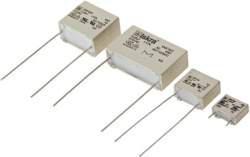
38 Capacirs Type KPB23xx KPB23xx black black Class X ± 4 ±2 ±3 d ± two-pole ast two numbers in the type designation (xx = 00 4) indicate the type of terminals and connecrs. Electrical connection R N R = 470 kω MΩ on request Technical data Standard values KPB23xx Construction paper impregnated Electrodes aluminium foil Rated voltage Capacitance lerance ± % Climatic category 2/00/2 acc. IEC 008- Passive flammability acc. IEC Temperature range C Test voltage 70 V DC, 2 s Insulation resistance at C, Um = 00 V DC, t = min Ri 000 MW for C 3 µf Ri Cn 00 for C > 3 µf Complies IEC/EN Capacitance Cx (µf) d x l Approvals: Casing: thermoplastic sealed with synthetical resin, flame retardant Wire dimensions on drawing correspond with type KPB standard version. Terminals Type KPB23xx 3 Type of terminals Insulated stranded wire mm2, or insulated solid wire ø mm. Non-insulated part is soldered.wires can be equipped with connection terminals on request. 8 x 30. x 30. x 30. x 30 x 30 2 x 30 4 x 3 x 3 8 x 3 8 x 40 x 3 x 40 x 40 2 x 40

 0.")
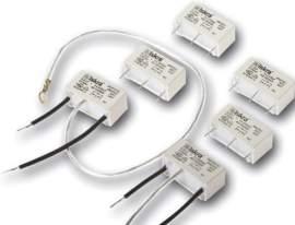
39 Capacirs Type KPR23xx KPR23xx black black Class X - RC units ± 4 ±2 ±3 d ± two-pole ast two numbers in the type designation (xx = 00 4) indicate the type of terminals and connecrs. Electrical connection X R N Technical data Standard values KPR23xx Dielectric paper impregnated Electrodes aluminium foil Rated voltage Capacitance lerance ± % Climatic category 2/08/2 acc. IEC 008- Passive flammability acc. IEC Temperature range C Test voltage 70 V DC, 2 s Complies IEC/EN Rated temperature uu C Casing: thermoplastic sealed with synthetical resin, flame retardant Capacitance Cx (µf) Resisr R (MW) d x l 2 x 30 x 3 Approval: Wire dimensions on drawing correspond with type KPR standard version. Terminals Type KPR23xx Type of terminals Insulated stranded wire mm2, or insulated solid wire ø mm. Non-insulated part is soldered.wires can be equipped with connection terminals on request. 37
40 Capacirs Type KPB3xx KPB3xx black transperent black ± ± d ± ±3 8 ±3 Class Y2 ±2 two-pole ast two numbers in the type designation (xx = 00 4) indicate the type of terminals and connecrs. Electrical connection PE N R = 470 kω MΩ on request Standard values KPB3xx Technical data Construction paper impregnated Electrodes aluminium foil Rated voltage Capacitance lerance ± % Climatic category 2/00/2 acc. IEC 008- Passive flammability acc. IEC Temperature range C Test voltage V AC, 2 s Insulation resistance at C, Um = 00 V DC, t = min Ri 000 MW for C 3 µf Complies IEC/EN Capacitance class Y2 (µf) D 2 x x x x x x x x x x x x x x x x x Approval: Casing: thermoplastic sealed with synthetical resin, flame retardant Wire dimensions on drawing correspond with type KPB300 - standard version. Terminals Type KPB3xx 38 Type of terminals Insulated stranded wire mm2, or insulated solid wire ø mm. Non-insulated part is soldered.wires can be equipped with connection terminals on request.
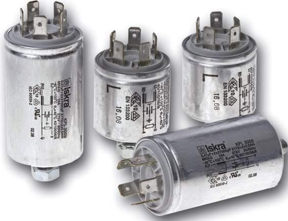
41 Capacirs Type KPB70xx KPB70xx black transperent black ± ± d ± ±3 8 ±3 Class XY2 ±2 8-2 two-pole ast two numbers in the type designation (xx = 00 4) indicate the type of terminals and connecrs. Electrical connection PE R N R = 470 kω MΩ on request Standard values KPB70xx Technical data Dielectric paper impregnated Electrodes aluminium foil Rated voltage, /0 Hz Capacitance lerance ± % Climatic category 2/00/2 acc. IEC 008- Passive flammability category A Temperature range C Test voltage X capacir 70 V DC, 2 s Y2 capacir V AC, 2 s Insulation resistance at C, Um = 00 V DC, t = min Ri 000 MW for C 3 µf Ri x Cn 00 s for C > 3 µf Complies IEC/EN Capacitance Capacitance class X (µf) class X2 (pf) x 00 2 x 00 2 x x x x 00 2 x x 00 2 x 00 2 x x x x x 00 2 x 200 d x l x 22 x 40 2 x x 40 2 x 40 2 x 40 2 x 40 2 x 40 2 x 40 2 x x 40 2 x x 40 2 x x x x x 40 Approval: Casing: aluminium can, closed with sealing washer, sealed with synthetical resin, flame retardant. Wire dimensions on drawing correspond with type KPB standard version. Terminals Type KPB70xx Type of terminals Insulated stranded wire mm2, or insulated solid wire ø mm. Non-insulated part is soldered.connection terminals provided on request. 3
42 Capacirs Type KPB7077 KPB N Earthing mark DIN 400 N Fast-on connecr.3x 0 ± Class XY2 ± 2 ± 40 ± four-pole X Y2 Y2 CASE N Electrical connection R = 470 kω MΩ on request Standard values KPB70xx Technical data Dielectric paper impregnated Electrodes aluminium foil Rated voltage Capacitance lerance ± % Climatic category 2/00/2 acc. IEC 008- Passive flammability category A Temperature range C Test voltage X capacir 70 V DC, 2 s Y2 capacir V AC, 2 s Insulation resistance at C, Um = 00 V DC, t = min Ri 000 MW for C 3 µf Ri x Cn 00 s for C > 3 µf Rated temperature uu 8 C Complies IEC/U/CSA Capacitance Capacitance class X (µf) class X2 (pf) x 00 2 x x 00 2 x 00 2 x x 00 2 x 00 2 x x 00 2 x 00 2 x x 00 2 x 0000 Approvals: C US IEC/ U/ CSA E Terminals 2 x double fast-on connecrs CuZn/Sn 40 d x l


43 Capacirs Type KPB73xx KPB73xx black transperent black ± ± d ± ±3 8 ±3 Class XY2 ±2 two-pole ast two numbers in the type designation (xx = 00 4) indicate the type of terminals and connecrs. Electrical connection X R Y2 Y2 PE N R = 470 kω MΩ on request Technical data Dielectric paper impregnated Electrodes aluminium foil Rated voltage 2 V AC, Capacitance lerance ± % Climatic category 2/00/2 acc. IEC 008- Passive flammability acc. IEC Temperature range C Test voltage X capacir 70 V DC, 2 s Y2 capacir V AC, 2 s Insulation resistance at C, Um = 00 V DC, t = min Ri 000 MW for C 3 µf Ri x Cn 00 s for C > 3 µf Complies IEC/U/CSA
44 Capacirs Type KPB73xx Casing: thermoplastic, sealed with synthetical resin, flame retardant. Wire dimensions on drawing correspond with type KPB standard version. Terminals Type of terminals Insulated stranded wire mm2, or insulated solid wire ø mm. Non-insulated part is soldered. Connection terminals provided on request. Type KPB73xx Standard values KPB73xx Capacitance Capacitance class X (µf) class Y2 (pf) x 00 2 x x 00 2 x x x 00 2 x 00 2 x x 00 2 x 00 2 x x 00 2 x 2 x 00 2 x x x 00 2 x 00 2 x x 00 2 x x 00 2 x x 00 2 x 00 2 x 00 2 x x 00 2 x x 00 2 x 00 2 x x 00 2 x x 00 2 x 200 d x l x 30 2 x 30 4 x 3 x 3 8 x 3 x 30 2 x 30 4 x 30 4 x 30 4 x 3 4 x 3 4 x 3 4 x 3 4 x 3 4 x 3 x 3 4 x 3 x 3 x 3 x 3 8 x 3 8 x 40 x 3 x 3 x 3 x 3 8 x 3 8 x 40 8 x 3 8 x 3 x 3 8 x 40 x 3 8 x 40 x 3 8 x 40 8 x 40 x 40 x x x 40 Capacitance Capacitance class X (µf) class Y2 (pf) x 2 x 00 2 x x 00 2 x x 00 2 x x 00 2 x x 00 2 x x 00 2 x x 00 2 x 00 2 x x x x 00 2 x x 00 2 x 00 2 x x x x x 00 2 x 200 Approval: C US IEC/ U/ CSA E d x l x 40 x 40 x 40 x 40 x x x x 40 x 40 x 40 x x x x 40 x 22 x x 40 2 x x 40 2 x 40 2 x 40 2 x 40 2 x 40 2 x 40 2 x x 40 2 x x 40 2 x x x x x 40
 class Y2 (pf) two-pole Technical data Dielectric paper impregnated Electrodes aluminium foil Rated voltage Capacitance")
45 Capacirs Type KPB732 KPB732 Electrical connection PE Y2 Y2 PE X N 2 R R = 470 kω MΩ on request Standard values KPB732 Capacitance Class XY2 class X (µf) class Y2 (pf) two-pole Technical data Dielectric paper impregnated Electrodes aluminium foil Rated voltage Capacitance lerance ± % Climatic category 2/00/2/B Temperature range C Test voltage X capacir 70 V DC, 2 s Y2 capacir V AC, 2 s Insulation resistance at C, Um = 00 V DC, t = min Ri 000 MW Casing thermoplastic can, sealed with synthetical resin, flame retardant Terminals fast-on connecrs.3x CuZn/Sn Complies IEC/U/CSA Rated temperature uu 8 C x 2 x 00 2 x x 00 2 x x 00 2 x x 2 x 00 2 x x 00 2 x x 00 2 x x 2 x 00 2 x x 00 2 x x 00 2 x x 00 2 x 2 x 00 2 x x 00 2 x x 00 2 x x 2 x 00 2 x x 00 2 x x 00 2 x 200 Approval: C US IEC/ U/ CSA E
46 Capacirs Type KPB734 Electrical connection PE Y2 Y2 PE X 2 N N2 N R R = 470 kω MΩ on request Class XY2 two-pole KPB734 Standard values KPB734 Technical data Capacitance Dielectric paper impregnated Electrodes aluminium foil Rated voltage Rated current A Capacitance lerance ± % Climatic category + letter indicating passive flammability category 2/00/2/B Temperature range C Test voltage X capacir 70 V DC, 2 s Y2 capacir V AC, 2 s Insulation resistance at C, Um = 00 V DC, t = min Ri 000 MW Casing thermoplastic can, sealed with synthetical resin, flame retardant Terminals fast-on connecrs.3x CuZn/Sn Complies IEC/U/CSA Rated temperature uu 8 C class X (µf) class Y2 (pf) x x x x x x x x 0.0 Approval: C US IEC/ U/ CSA E0384-4


 class Y2 (pf) 0.")
47 Capacirs Type KPB742 Electrical connection KPB742 Fixing plate with earth symbol DIN 400-B-T impressed mm Tabs, N:.3 x DIN IEC ± ± R Y2 Y2 X PE N R = 470 kω MΩ on request Marking ± Class XY2 two-pole Tabs, N:.3 x DIN IEC ± ± Fixing hooks ±0. ± 2 ± Technical data Standard values KPB742 Dielectric paper impregnated Electrodes aluminium foil Rated voltage Capacitance lerance ± % Climatic category 2/00/2/C Temperature range C Test voltage X capacir 70 V DC, 2 s Y2 capacir V AC, 2 s Insulation resistance at C, Um = 00 V DC, t = min Ri 000 MW for C 3 µf Casing thermoplastic can, sealed with synthetical resin, flame retardant Terminals 3x fast-on connecrs.3x CuZn/Sn Complies IEC/EN Capacitance class X (µf) class Y2 (pf) 0. 2 x 00 2 x 00 Other values upon request Approval: IEC

48 Capacirs Type KNB742 Electrical connection KNB742 3 ± Earth symbol DIN 400-B-T PE 2 ±0.2 PE Y2 0 ± N R = MΩ 3. ±2 f3.3 ±0 R 3x.8 ±2 Class XY2 Y2 X four-pole 4 ± 28. ± ± ±0. ± RAST W ± Standard values KNB742 Capacitance Technical data class X (µf) class Y2 (pf) Dielectric polypropylene film, metallized Rated voltage Rated current A Rated temperature uu 8 C Capacitance lerance ± % Climatic category - letter indicating passive category 2/00/2/C Temperature range C Test voltage X capacir 70 V DC, 2 s Y2 capacir V AC, 2 s Insulation resistance at C, Um = 00 V DC, t = min Ri 000 MW Casing thermoplastic can, sealed with synthetical resin, flame retardant Terminals fast-on connecrs.3x CuZn/Sn Complies IEC/EN Approval: IEC x 20
49 Capacirs Type KPB83xx Electrical connection Y2 Y2 2 N X R R = 470 kω MΩ on request Standard values KPB83xx Class XY2 four-pole ast two numbers in the type designation (xx = 00 4) indicate the type of terminals and connecrs. KPB83xx blue transperent ± ± 8 black ±3 d± ±2 ±3 Technical data Dielectric paper impregnated Electrodes aluminium foil Rated current A Rated voltage Capacitance lerance ± % Climatic category 2/08/2 acc. IEC 008- Passive flammability acc. IEC Temperature range C Test voltage X capacir 70 V DC, 2 s Y2 capacir 800 V AC, 2 s Insulation resistance at C, Um = 00 V DC, t = min Ri 000 MW for C 3 µf Ri x Cn 00 s for C > 3 µf Complies IEC/EN Capacitance class X (µf) class Y2 (pf) d x Approval: Casing: thermoplastic sealed with synthetical resin, flame retardant Wire dimensions on drawing correspond with type KPB8300 standard version. 2 x 00 2 x 00 2 x 00 2 x x 00 2 x 00 2 x x 00 2 x 00 2 x x x 00 2 x x 00 2 x x 00 2 x x 00 2 x 00 2 x 00 2 x x 00 2 x x 00 2 x 00 2 x x 00 2 x x 00 2 x x 00 2 x x 00 2 x x 00 2 x 200 x 30 x 30 2 x 30 4 x 30 4 x 30 4 x 3 4 x 3 4 x 3 4 x 3 4 x 3 x 3 4 x 3 x 3 x 3 8 x 3 8 x 3 x 3 x 3 x 3 8 x 3 8 x 40 8 x 3 8 x 3 x 3 x 3 22 x 40 8 x 40 x 3 8 x 40 8 x 40 x 40 x x x 40 x 40 x 3 x x x x 40 x 22 x 40 Other values upon request IEC Terminals Type KPB83xx Type of terminals Insulated stranded wire mm2, or insulated solid wire ø mm. Non-insulated part is soldered. Wires can be equipped with connection terminals on request. 47
50 Filters for Radio Interference Suppression Type KP3008 Electrical connection 3 Cy R Cx Cy 2 4 R = 470 kω MΩ on request Class XY2 KP3008 Fast-on connecr.3 DIN 2 M8 Earthing mark DIN ± l ± Technical data Dielectric paper impregnated Electrodes aluminium foil Rated voltage Capacitance lerance ± % Inductance lerance -30 % + % Test voltage X capacir 70 V DC, 2 s Y2 capacir V AC, 2 s (or 3000 V DC, 2 s) Insulation resistance at C, Um = 00 V DC, t = min Ri 000 MW for C 3 µf Ri x Cn 00 s for C > 3 µf Complies IEC/EN 03-2, Ul283, CSA C22.2 No. 8 capacir part IEC Casing: aluminium can, closed with sealing washer. Terminals Type Type of terminals KP fast-on connecrst. 48
 Y2 (pf) 2 x 20 2 x 00 0.")
51 Filters for Radio Interference Suppression Type KP3008 Standard values KP 3008 for upper temperature 00 C Nominal values Current I (A)/T( C) 7/40 7/40 0/40 0/40 /40 /40 /40 /40 0/70 0/70 0/70 0/70 0/40 0/40 2./40 2./40 2./40 2./40 2./40 2./40 /40 /40 /40 /40 /40 0/70 0/70 0/70 0/70 0/70 3/40 2./40 3/40 0/40 0/40 2./40 2./40 2./40 2./40 2./40 /40 /40 /40 /40 /40 0/70 0/70 0/70 0/70 0/70 X (µf) Y2 (pf) 2 x 20 2 x x 20 2 x 20 2 x x 0 2 x x 20 Inductance (mh) Approvals for climatic category 40/00/ according IRC 008- Discharging resisr R (mw).... Nominal values for capacitance: IEC * µf + 2 x 20 pf µf + 2 x 20 pf * µf + 2 x 4700 pf µf + 2 x 00 pf µf + 2 x 0000 pf µf + 2 x 00 pf * 0.2 µf + 2 x 20 pf 0.2 µf + 2 x 00 pf * 0.2 µf + 2 x 4700 pf 0.2 µf + 2 x 00 pf 0.2 µf + 2 x 0000 pf * 0.2 µf + 2 x 00 pf * 0.2 µf + 2 x 8000 pf 0.2 µf + 2 x 000 pf * 0.2 µf + 2 x 200 pf * 0.2 µf + 2 x 0 pf 0.2 µf + pf * µf + 2 x 20 pf * µf + 2 x 00 pf µf + 2 x 4700 pf µf + 2 x 00 pf µf + 2 x 0000 pf µf + 2 x 00 pf * µf + 2 x 8000 pf µf + 2 x 000 pf * µf + 2 x 200 pf µf + 2 x 0 pf µf + pf µf + 2 x 20 pf µf + 2 x 00 pf µf + 2 x 4700 pf µf + 2 x 00 pf µf + 2 x 0000 pf µf + 2 x 00 pf µf + 2 x 8000 pf µf + 2 x 000 pf µf + 2 x 200 pf µf + 2 x 0 pf µf + pf * Only for IEC 03-2 Approvals in use 4
52 Filters for Radio Interference Suppression Type KP300 Electrical connection 3 Cy R Cx Cy 2 4 R = 470 kω MΩ on request Class XY2 KP300 Earthing mark DIN 400 KNB73x M8 Fast-on connecr.3 DIN 2 2 ± l ± Technical data Dielectric paper impregnated Electrodes aluminium foil Rated voltage Capacitance lerance ± % Inductance lerance -30 % + % Test voltage X capacir 70 V DC, 2 s Y2 capacir V AC, 2 s (or 3000 V DC, 2 s) shields against casing V AC, 2 s (only filters where Y2 - capacir is not connected casing) Insulation resistance at C, Um = 00 V DC, t = min Ri 000 MW for C 3 µf Ri x Cn 00 s for C > 3 µf Complies IEC/EN 03-2, Ul283, CSA C22.2 No. 8 capacir part IEC Casing: aluminium can, closed with sealing washer. Terminals Type Type of terminals KP300 fast-on connecrst.
 Y2 (pf) 2 x 20 2 x 00 0.")
53 Filters for Radio Interference Suppression Type KP300 Standard values KP 300 for upper temperature 00 C Nominal values Current I (A)/T( C) 7/40 7/40 0/40 0/40 /40 /40 /40 /40 0/70 0/70 0/70 0/70 0/40 0/40 2./40 2./40 2./40 2./40 2./40 2./40 /40 /40 /40 /40 /40 0/70 0/70 0/70 0/70 0/70 3/40 2./40 3/40 0/40 0/40 2./40 2./40 2./40 2./40 2./40 /40 /40 /40 /40 /40 0/70 0/70 0/70 0/70 0/70 X (µf) Y2 (pf) 2 x 20 2 x x 20 2 x 20 2 x x 0 2 x x 20 Inductance (mh) Approvals for climatic category 40/00/ according IEC 008- Discharging resisr R (mw).... Nominal values for capacitance: IEC * µf + 2 x 20 pf µf + 2 x 20 pf * µf + 2 x 4700 pf µf + 2 x 00 pf µf + 2 x 0000 pf µf + 2 x 00 pf * 0.2 µf + 2 x 20 pf 0.2 µf + 2 x 00 pf * 0.2 µf + 2 x 4700 pf 0.2 µf + 2 x 00 pf 0.2 µf + 2 x 0000 pf * 0.2 µf + 2 x 00 pf * 0.2 µf + 2 x 8000 pf 0.2 µf + 2 x 000 pf * 0.2 µf + 2 x 200 pf * 0.2 µf + 2 x 0 pf 0.2 µf + pf * µf + 2 x 20 pf * µf + 2 x 00 pf µf + 2 x 4700 pf µf + 2 x 00 pf µf + 2 x 0000 pf µf + 2 x 00 pf * µf + 2 x 8000 pf µf + 2 x 000 pf * µf + 2 x 200 pf µf + 2 x 0 pf µf + pf µf + 2 x 20 pf µf + 2 x 00 pf µf + 2 x 4700 pf µf + 2 x 00 pf µf + 2 x 0000 pf µf + 2 x 00 pf µf + 2 x 8000 pf µf + 2 x 000 pf µf + 2 x 200 pf µf + 2 x 0 pf µf + pf * Only for IEC 03-2 Approvals in use
54 Filters for Radio Interference Suppression Type KP3023 Electrical connection Cy R Cx Cy R = 470 kω MΩ on request Class XY2 KP3023 Fast-on connecr.3 DIN 2 Earthing mark DIN 400 M8 B 2B 2A A 2 ± l ± Technical data Dielectric paper impregnated Electrodes aluminium foil Rated voltage Capacitance lerance ± % Inductance lerance -30 % + % Test voltage X capacir 70 V DC, 2 s Y2 capacir V AC, 2 s (or 3000 V DC, 2 s) shields against casing V AC, 2 s Insulation resistance at C, Um = 00 V DC, t = min Ri 000 MW for C 3 µf Ri x Cn 00 s for C > 3 µf Complies IEC/EN 03-2, U283, CSA C22.2 No. 8 capacir part IEC Casing: aluminium can, closed with sealing washer. Terminals Type Type of terminals KP A, 2A and B, 2B for RAST - 2 x fast-on connecrs 2 A 2A B 2B
 Y2 (pf) 2 x 20 2 x 00 0.")
55 Filters for Radio Interference Suppression Type KP3023 Standard values KP 3023 for upper temperature 00 C Nominal values Current I (A)/T( C) 7/40 7/40 0/40 0/40 /40 /40 /40 /40 0/70 0/70 0/70 0/70 0/40 0/40 2./40 2./40 2./40 2./40 2./40 2./40 /40 /40 /40 /40 /40 0/70 0/70 0/70 0/70 0/70 3/40 2./40 /40 3/40 0/40 0/40 2./40 2./40 2./40 2./40 2./40 /40 /40 /40 /40 /40 0/70 0/70 0/70 0/70 0/70 X (µf) Y2 (pf) 2 x 20 2 x x 20 2 x 20 2 x x 0 2 x 00 2 x x 20 Inductance (mh) Approvals for climatic category 40/00/ according IEC 008- Discharging resisr R (mw).... Nominal values for capacitance: IEC * µf + 2 x 20 pf * µf + 2 x 00 pf µf + 2 x 4700 pf µf + 2 x 00 pf µf + 2 x 0000 pf µf + 2 x 00 pf * 0.2 µf + 2 x 00 pf 0.2 µf + 2 x 4700 pf 0.2 µf + 2 x 00 pf * 0.2 µf + 2 x 0000 pf * 0.2 µf + 2 x 00 pf 0.2 µf + 2 x 8000 pf * 0.2 µf + 2 x 000 pf 0.2 µf + 2 x 200 pf 0.2 µf + 2 x 0 pf 0.2 µf + pf * µf + 2 x 00 pf µf + 2 x 4700 pf µf + 2 x 00 pf µf + 2 x 0000 pf * µf + 2 x 00 pf µf + 2 x 8000 pf * µf + 2 x 000 pf µf + 2 x 200 pf µf + 2 x 0 pf µf + pf * µf + 2 x 20 pf * µf + 2 x 00 pf * µf + 2 x 4700 pf * µf + 2 x 00 pf * µf + 2 x 0000 pf * µf + 2 x 00 pf * µf + 2 x 8000 pf * µf + 2 x 000 pf * µf + 2 x 200 pf * µf + 2 x 0 pf * µf + pf * Only for IEC 03-2 Approvals in use 3
56 Filters for Radio Interference Suppression Type KP3024 Electrical connection Cy R Cx Cy R = 470 kω MΩ on request Class XY2 KP3024 Fast-on connecr.3 DIN 2 M8 Earthing mark DIN ± l ± Technical data Dielectric paper impregnated Electrodes aluminium foil Rated voltage Capacitance lerance ± % Inductance lerance -30 % + % Test voltage X capacir 70 V DC, 2 s Y2 capacir V AC, 2 s (3000 V DC, 2 s) Insulation resistance at C, Um = 00 V DC, t = min Ri 000 MW for C 3 µf Ri x Cn 00 s for C > 3 µf Complies IEC/EN 03-2, U283, CSA C22.2 No. 8 capacir part IEC Casing: aluminium can, closed with sealing washer. Terminals Type Type of terminals KP for RAST - 2 x fast-on connecrs 4
 Y2 (pf) 2 x 20 2 x 00 0.")
57 Filters for Radio Interference Suppression Type KP3024 Standard values KP 3024 for upper temperature 00 C Nominal values Current I (A)/T( C) 7/40 7/40 0/40 0/40 /40 /40 /40 /40 0/70 0/70 0/70 0/70 0/40 0/40 2./40 2./40 2./40 2./40 2./40 2./40 /40 /40 /40 /40 /40 0/70 0/70 0/70 0/70 0/70 3/40 2./40 /40 3/40 0/40 0/40 2./40 2./40 2./40 2./40 2./40 /40 /40 /40 /40 /40 0/70 0/70 0/70 0/70 0/70 X (µf) Y2 (pf) 2 x 20 2 x x 20 2 x 20 2 x x 0 2 x 00 2 x x 20 Inductance (mh) Approvals for climatic category 40/00/ according IEC 008- Discharging resisr R (mw).... Nominal values for capacitance: IEC * µf + 2 x 20 pf µf + 2 x 00 pf * µf + 2 x 4700 pf µf + 2 x 00 pf µf + 2 x 0000 pf µf + 2 x 00 pf * 0.2 µf + 2 x 20 pf 0.2 µf + 2 x 00 pf * 0.2 µf + 2 x 4700 pf 0.2 µf + 2 x 00 pf 0.2 µf + 2 x 0000 pf * 0.2 µf + 2 x 00 pf * 0.2 µf + 2 x 8000 pf 0.2 µf + 2 x 000 pf * 0.2 µf + 2 x 200 pf * 0.2 µf + 2 x 0 pf * µf + 2 x 20 pf * µf + 2 x 00 pf µf + 2 x 4700 pf µf + 2 x 00 pf µf + 2 x 0000 pf µf + 2 x 00 pf * µf + 2 x 8000 pf µf + 2 x 000 pf * µf + 2 x 200 pf µf + 2 x 0 pf * µf + 2 x 20 pf * µf + 2 x 00 pf * µf + 2 x 4700 pf * µf + 2 x 00 pf * µf + 2 x 0000 pf * µf + 2 x 00 pf * µf + 2 x 8000 pf * µf + 2 x 000 pf * µf + 2 x 200 pf * µf + 2 x 0 pf * µf + pf * Only for IEC 03-2 Approvals in use
58 Filters for Radio Interference Suppression Type KP38 Electrical connection Cy R Cx Cy R = 470 kω MΩ on request Casing: aluminium can, sealed with synthetical resin, flame retardant Terminals Class XY2 Type Type of terminals KP38 fast-on connecrs KP38 4 ± ± 0 ± 28. ± 2. ± 3 ± 3 ± 2 ±0.2 ± H ± W 4 ± ± 7 ± 4 ± Technical data Dielectric paper impregnated Electrodes aluminium foil Rated voltage Capacitance lerance ± % Inductance lerance -30 % + % Test voltage X capacir 70 V DC, 2 s Y2 capacir V AC, 2 s (3000 V DC, 2 s) Insulation resistance at C, Um = 00 V DC, t = min Ri 000 MW for C 3 µf Ri x Cn 00 s for C > 3 µf Complies IEC/EN 03-2, U283, CSA C22.2 No. 8 capacir part IEC
 0.")
59 Filters for Radio Interference Suppression Type KP38 Standard values KP 38 for upper temperature 00 C Current I (A)/T( C) 0/40 0/40 0/40 0/40 2./40 2./40 2./40 2./40 2./40 2./40 /40 /40 /40 0/70 0/70 0/70 0/40 0/40 0/40 0/40 2./40 2./40 2./40 2./40 2./40 2./40 /40 /40 /40 0/70 0/70 0/70 0/40 0/40 0/40 0/40 2./40 2./40 2./40 2./40 2./40 2./40 /40 /40 /40 0/70 0/70 0/70 X (µf) Y2 (pf) 2 x 20 2 x 20 2 x 20 Nominal values Discharging Inductance resisr R (mh) (mw) H W IEC 03-2 Nominal values for capacitance: 0.2 µf + 2 x 20 pf 0.2 µf + 2 x 00 pf 0.2 µf + 2 x 4700 pf 0.2 µf + 2 x 00 pf 0.2 µf + 2 x 0000 pf 0.2 µf + 2 x 00 pf 0.2 µf + 2 x 000 pf 0.2 µf + 2 x 200 pf 0.2 µf + 2 x 0 pf 0.2 µf + pf 3 µf + 2 x 20 pf 3 µf + 2 x 00 pf 3 µf + 2 x 4700 pf 3 µf + 2 x 00 pf 3 µf + 2 x 0000 pf 3 µf + 2 x 00 pf 3 µf + 2 x 000 pf 3 µf + 2 x 200 pf 3 µf + 2 x 0 pf µf + 2 x 20 pf µf + 2 x 00 pf µf + 2 x 4700 pf µf + 2 x 00 pf µf + 2 x 0000 pf µf + 2 x 00 pf µf + 2 x 000 pf µf + 2 x 200 pf µf + 2 x 0 pf Approvals in use 7
60 Filters for Radio Interference Suppression Type KP38 Standard values KP 38 for upper temperature 00 C Current I (A)/T( C) 0/40 0/40 0/40 0/40 2./40 2./40 2./40 2./40 2./40 2./40 /40 /40 /40 0/70 0/70 0/70 0/40 0/40 0/40 0/40 2./40 2./40 2./40 2./40 2./40 2./40 /40 /40 /40 0/70 0/70 0/70 0/40 0/40 0/40 0/40 2./40 2./40 2./40 2./40 2./40 2./40 /40 /40 /40 0/70 0/70 0/70 X (µf) 0. Y2 (pf) 2 x 20 2 x 20 2 x 20 Nominal values Discharging Inductance resisr R (mh) (mw) H W IEC 03-2 Nominal values for capacitance: 0. µf + 2 x 20 pf 0. µf + 2 x 00 pf 0. µf + 2 x 4700 pf 0. µf + 2 x 00 pf 0. µf + 2 x 0000 pf 0. µf + 2 x 00 pf 0. µf + 2 x 000 pf 0. µf + 2 x 200 pf 0. µf + 2 x 0 pf 0. µf + pf µf + 2 x 20 pf µf + 2 x 00 pf µf + 2 x 4700 pf µf + 2 x 00 pf µf + 2 x 0000 pf µf + 2 x 00 pf µf + 2 x 000 pf µf + 2 x 200 pf µf + 2 x 0 pf µf + 2 x 20 pf µf + 2 x 00 pf µf + 2 x 4700 pf µf + 2 x 00 pf µf + 2 x 0000 pf µf + 2 x 00 pf µf + 2 x 000 pf µf + 2 x 200 pf µf + 2 x 0 pf Approvals in use 8

61 Filters for Radio Interference Suppression Type KP323 Electrical connection A 2A Cy R Cx B 2B Cy R = 470 kω MΩ on request Casing: aluminium can, sealed with synthetical resin, flame retardant Terminals Type of terminals Type Class XY2 - A, 2A and B, 2B for RAST - 2 x fast-on connecrs KP323 KP323 ± 2. ± ± 3 ± 2 ±0.2 3 ± 4 B 0 ± 2B 28. A 2A ±0.2 2,2 7 ± H W 7 4 Technical data Dielectric paper impregnated Electrodes aluminium foil Rated voltage 2 V AC, Capacitance lerance ± % Inductance lerance -30 % + % Test voltage X capacir 70 V DC, 2 s Y2 capacir V AC, 2 s (3000 V DC, 2 s) Insulation resistance at C, Um = 00 V DC, t = min Ri 000 MW for C 3 µf Ri x Cn 00 s for C > 3 µf Complies IEC/EN 03-2, U283, CSA C22.2 No. 8 capacir part IEC
62 Filters for Radio Interference Suppression Type KP323 Standard values KP 323 for upper temperature 00 C Current I (A)/T( C) 0/40 0/40 0/40 0/40 2./40 2./40 2./40 2./40 2./40 2./40 /40 /40 /40 0/70 0/70 0/70 0/40 0/40 0/40 0/40 2./40 2./40 2./40 2./40 2./40 2./40 /40 /40 /40 0/70 0/70 0/70 0/40 0/40 0/40 0/40 2./40 2./40 2./40 2./40 2./40 2./40 /40 /40 /40 0/70 0/70 0/70 X (µf) Y2 (pf) 2 x 20 2 x 20 2 x 20 Nominal values Discharging Inductance resisr R (mh) (mw) H W IEC 03-2 Nominal values for capacitance: 0.2 µf + 2 x 20 pf 0.2 µf + 2 x 00 pf 0.2 µf + 2 x 4700 pf 0.2 µf + 2 x 00 pf 0.2 µf + 2 x 0000 pf 0.2 µf + 2 x 00 pf 0.2 µf + 2 x 000 pf 0.2 µf + 2 x 200 pf 0.2 µf + 2 x 0 pf 0.2 µf + pf 3 µf + 2 x 20 pf 3 µf + 2 x 00 pf 3 µf + 2 x 4700 pf 3 µf + 2 x 00 pf 3 µf + 2 x 0000 pf 3 µf + 2 x 00 pf 3 µf + 2 x 000 pf 3 µf + 2 x 200 pf 3 µf + 2 x 0 pf µf + 2 x 20 pf µf + 2 x 00 pf µf + 2 x 4700 pf µf + 2 x 00 pf µf + 2 x 0000 pf µf + 2 x 00 pf µf + 2 x 000 pf µf + 2 x 200 pf µf + 2 x 0 pf Approvals in use 0
63 Filters for Radio Interference Suppression Type KP323 Standard values KP 323 for upper temperature 00 C Current I (A)/T( C) 0/40 0/40 0/40 0/40 2./40 2./40 2./40 2./40 2./40 2./40 /40 /40 /40 0/70 0/70 0/70 0/40 0/40 0/40 0/40 2./40 2./40 2./40 2./40 2./40 2./40 /40 /40 /40 0/70 0/70 0/70 0/40 0/40 0/40 0/40 2./40 2./40 2./40 2./40 2./40 2./40 /40 /40 /40 0/70 0/70 0/70 /40 X (µf) 0. Y2 (pf) 2 x 20 2 x 20 2 x 20 Nominal values Discharging Inductance resisr R (mh) (mw) H W IEC 03-2 Nominal values for capacitance: 0. µf + 2 x 20 pf 0. µf + 2 x 00 pf 0. µf + 2 x 4700 pf 0. µf + 2 x 00 pf 0. µf + 2 x 0000 pf 0. µf + 2 x 00 pf 0. µf + 2 x 000 pf 0. µf + 2 x 200 pf 0. µf + 2 x 0 pf 0. µf + pf µf + 2 x 20 pf µf + 2 x 00 pf µf + 2 x 4700 pf µf + 2 x 00 pf µf + 2 x 0000 pf µf + 2 x 00 pf µf + 2 x 000 pf µf + 2 x 200 pf µf + 2 x 0 pf µf + 2 x 20 pf µf + 2 x 00 pf µf + 2 x 4700 pf µf + 2 x 00 pf µf + 2 x 0000 pf µf + 2 x 00 pf µf + 2 x 000 pf µf + 2 x 200 pf µf + 2 x 0 pf Approvals in use
64 Filters for Radio Interference Suppression Type KP324 Electrical connection Cy R Cx Cy R = 470 kω MΩ on request Casing: aluminium can, sealed with synthetical resin, flame retardant Terminals Type of terminals Type Class XY2 - for RAST - 2 x fast-on connecrs KP324 KP324 3 ± 2 ±0.2 3 ± ± 2. ± ± 7 ± H ± W ± 7 ± 4 ± Technical data 2 Dielectric paper impregnated Electrodes aluminium foil Rated voltage 2 V AC, Capacitance lerance ± % Inductance lerance -30 % + % Test voltage X capacir 70 V DC, 2 s Y2 capacir V AC, 2 s (3000 V DC, 2 s) Insulation resistance at C, Um = 00 V DC, t = min Ri 000 MW for C 3 µf Ri x Cn 00 s for C > 3 µf Complies IEC/EN 03-2, U283, CSA C22.2 No. 8 capacir part IEC ± ± ±0.2
 0.")
65 Filters for Radio Interference Suppression Type KP324 Standard values KP 324 for upper temperature 00 C Current I (A)/T( C) 0/40 0/40 0/40 0/40 2./40 2./40 2./40 2./40 2./40 2./40 /40 /40 /40 0/70 0/70 0/70 0/40 0/40 0/40 0/40 2./40 2./40 2./40 2./40 2./40 2./40 /40 /40 /40 0/70 0/70 0/70 0/40 0/40 0/40 0/40 2./40 2./40 2./40 2./40 2./40 2./40 /40 /40 /40 0/70 0/70 0/70 X (µf) Y2 (pf) 2 x 20 2 x 20 2 x 20 Nominal values Discharging Inductance resisr R (mh) (mw) H W IEC 03-2 Nominal values for capacitance: 0.2 µf + 2 x 20 pf 0.2 µf + 2 x 00 pf 0.2 µf + 2 x 4700 pf 0.2 µf + 2 x 00 pf 0.2 µf + 2 x 0000 pf 0.2 µf + 2 x 00 pf 0.2 µf + 2 x 000 pf 0.2 µf + 2 x 200 pf 0.2 µf + 2 x 0 pf 0.2 µf + pf 3 µf + 2 x 20 pf 3 µf + 2 x 00 pf 3 µf + 2 x 4700 pf 3 µf + 2 x 00 pf 3 µf + 2 x 0000 pf 3 µf + 2 x 00 pf 3 µf + 2 x 000 pf 3 µf + 2 x 200 pf 3 µf + 2 x 0 pf µf + 2 x 20 pf µf + 2 x 00 pf µf + 2 x 4700 pf µf + 2 x 00 pf µf + 2 x 0000 pf µf + 2 x 00 pf µf + 2 x 000 pf µf + 2 x 200 pf µf + 2 x 0 pf Approvals in use 3
66 Filters for Radio Interference Suppression Type KP324 Standard values KP 324 for upper temperature 00 C Current I (A)/T( C) 0/40 0/40 0/40 0/40 2./40 2./40 2./40 2./40 2./40 2./40 /40 /40 /40 0/70 0/70 0/70 0/40 0/40 0/40 0/40 2./40 2./40 2./40 2./40 2./40 2./40 /40 /40 /40 0/70 0/70 0/70 0/40 0/40 0/40 0/40 2./40 2./40 2./40 2./40 2./40 2./40 /40 /40 /40 0/70 0/70 0/70 X (µf) 0. Y2 (pf) 2 x 20 2 x 20 2 x 20 Nominal values Discharging Inductance resisr R (mh) (mw) H W IEC 03-2 Nominal values for capacitance: 0. µf + 2 x 20 pf 0. µf + 2 x 00 pf 0. µf + 2 x 4700 pf 0. µf + 2 x 00 pf 0. µf + 2 x 0000 pf 0. µf + 2 x 00 pf 0. µf + 2 x 000 pf 0. µf + 2 x 200 pf 0. µf + 2 x 0 pf 0. µf + pf µf + 2 x 20 pf µf + 2 x 00 pf µf + 2 x 4700 pf µf + 2 x 00 pf µf + 2 x 0000 pf µf + 2 x 00 pf µf + 2 x 000 pf µf + 2 x 200 pf µf + 2 x 0 pf µf + 2 x 20 pf µf + 2 x 00 pf µf + 2 x 4700 pf µf + 2 x 00 pf µf + 2 x 0000 pf µf + 2 x 00 pf µf + 2 x 000 pf µf + 2 x 200 pf µf + 2 x 0 pf Approvals in use 4
 X (µf) Y2 (pf) (mh) d x l Technical data Construction: - capacir paper impregnated Electrodes aluminium foil Rated voltage")
67 Filters for Radio Interference Suppression Type KP3300 KP3300 red black yellow-green or neutral black red ± l + d 0, Class XY2 Electrical connection Cy Cx Cy R = 470 kω MΩ on request Standard values KP3300 Rated values Current Inductance I (A) X (µf) Y2 (pf) (mh) d x l Technical data Construction: - capacir paper impregnated Electrodes aluminium foil Rated voltage 2 V AC, Capacitance lerance ± % Inductance lerance -30 % + % Climatic category 2/8/2 acc. IEC 008- Temperature range C Test voltage X - capacir 2 V DC, 2 s for UR = 2 V X - capacir 70 V DC, 2 s for UR = V Y2 - capacir 00 V DC, 2 s (or 800 V AC, 2 s) Insulation resistance at C, Um = 00 V DC, t = min Ri 000 MW for C 3 µf Ri x Cn 00 s for C > 3 µf Complies IEC/EN 03-2, capacir section IEC x 2 x 2 x 2 x 2 x 2x 2x 2x4 2x2 2x 2 x 2 x 2 x 2 x 2 x Casing: thermoplastic, sealed with synthetical resin. Terminals Type Type of terminals KP3300 stranded wire mm2 with PVC insulation
Electromagnetic Interference Suppression Capacitors Class X2 305/310VAC TECHNICAL SPECIFICATION. Metallized Polypropylene Film Capacitors (MKP)
") Electromagnetic Interference Suppression Capacitors Class X2 305/310VAC ISKRA, d.d. Type: KNB1580 Issue: April 2018 PE ISKRA KONDENZATORJI d.d., Vajdova ulica 71, 8333 Semič, SLOVENIA Phone: +386 738 49
Electromagnetic Interference Suppression Capacitors Class X2 305/310VAC ISKRA, d.d. Type: KNB1580 Issue: April 2018 PE ISKRA KONDENZATORJI d.d., Vajdova ulica 71, 8333 Semič, SLOVENIA Phone: +386 738 49
Film Capacitors. EMI suppression capacitors. Date: June 2018
 Film Capacitors EMI suppression capacitors Date: June 2018 EPCOS AG 2018. Reproduction, publication and dissemination of this publication, enclosures hereto and the information contained therein without
Capacitors for Use in Electronics
 Capacitors for Use in Electronics Capacitors 1 Contents General information on Iskra Capacitors for use in electronics Type Construction of capacitors Class Page KFU polyester capacitors (KT) 13 KEU metallized
Capacitors. Typical electrical characteristics of metallized polyester capacitors KEU. Type KEU Metallized polyester capacitors
 Capacitors Type KEU Metallized polyester capacitors As a dielectric high quality polyester film with good electrical properties is used. Electrodes of capacitor are vacuum metallized aluminium. The thickness
Interference suppression film capacitors MKP 336 1
 MKP RADIAL POTTED TYPE PITCH /15/22.5/27.5 mm l b h lt P d t CBA196 Fig.1 Simplified outlines. FEATURES to 27.5 mm lead pitch Supplied loose in box and taped on reel Consists of a low-inductive wound cell
R.46. X2 CLASS (IEC ) - MKP Series SELF-HEALING PROPERTIES 09/
 - MKP Series SELF-HEALING PROPERTIES 09/") Loose Taped X CLASS (IEC 60384-4) - MKP Series Typical applications: interference suppression and «across-the-line» applications. Suitable for use in situations where failure of the capacitor would not
Loose Taped X CLASS (IEC 60384-4) - MKP Series Typical applications: interference suppression and «across-the-line» applications. Suitable for use in situations where failure of the capacitor would not
Metallized Polypropylene Film Capacitor Related Document: IEC
 MKP 184 Metallized Polypropylene Film Capacitor Related Document: IEC 6084-16 MAIN APPLICATIONS: High voltage, high current and high pulse operations, deflection circuits in TV sets (S-correction and fly-back
Metallized polyester film capacitors MKT 470
 MKT RADIAL POTTED TYPE PITCH 5 mm CBA141 Fig.1 Simplified outlines. FEATURES Low-inductive wound cell of metallized (PETP) film Potted with epoxy resin in a flame-retardant case Radial leads of solder-coated
TPC Suppressor Capacitors Classes X & Y A KYOCERA GROUP COMPANY
 Suppressor Capacitors Classes X & Y A KYOCERA GROUP COMPANY Contents General Technical Information on Interference Suppression..... 2 Ordering Code......................................... 3 QX Series
Metallized Polypropylene Film Capacitor Related Document: IEC
 Related Document: IEC 6084-16 MKP 184 Dimensions in millimeters 40.0 ±.0 L 40.0 ±.0 Max. MAIN APPLICATIONS High voltage, high current and high pulse operations, deflection circuits in TV sets (S-correction
Characteristics and Definitions Used for Film Capacitors
 Characteristics and Definitions Used for Film Capacitors COMMON FILM DIELECTRICS USED IN FILM CAPACITORS PRODUCTS PARAMETER DIELECTRIC (1) UNIT Dielectric constant 1 khz 3.3 3 3. - Dissipation factor 1
DC Film Capacitors MKT Axial Type
 MKT181 DC Film Capacitors MKT Axial Type FEATURES Supplied loose in box, taped on ammopack or reel Material categorization: For definitions of compliance please see www.vishay.com/doc?9991 APPLICATIONS
Metallized Polyester Film Capacitors MKT Radial Potted Type
 www.vishay.com Metallized Polyester Film Capacitors MKT Radial Potted Type FEATURES 7.5 mm lead pitch Supplied loose in box and taped on reel or ammopack Material categorization: for definitions of compliance
Varistors to
 FEATURES Zinc oxide disc, epoxy coated Straight leads Straight leads with flange (2322 592 and 593 series only) Kinked leads. APPLICATION Suppression of transients. DESCRIPTION The varistors consist of
AC Line Rated Ceramic Disc Capacitors Class X1, 760 V AC, Class Y1, 500 V AC
 AC Line Rated Ceramic Disc Capacitors Class X1, 760 V AC, Class Y1, 500 V AC FEATURES Complying with IEC 60384-14 4 th edition Can pass 10 kv pulses (10 per polarity) Withstands 85 / 85 / 1000 h test Reduced
Suppressor film capacitor Highlight and Application in Series with the main
 Suppressor film capacitor Highlight and Application in Series with the main April 2007 Paola Bettacchi - Product Manager 1 Film capacitor : main features and performances Process flow charts Self-healing
AC and Pulse Metallized Polypropylene Film Capacitors MKP Radial Potted Type
 AC and Pulse Metallized Polypropylene Film Capacitors MKP Radial Potted Type FEATURES 5 mm to 37.5 mm lead pitch Material categorization: for definitions of compliance please see www.vishay.com/doc?9992
AC Line Rated Ceramic Disc Capacitors Class X1, 760 V AC, Class Y1, 500 V AC
 AC Line Rated Ceramic Disc Capacitors Class X1, 760 V AC, Class Y1, 500 V AC FEATURES Complying with IEC 60384-14 4 th edition High reliability Vertical (inline) kinked or straight leads Singlelayer AC
Snubber MMKP 386 AC and pulse double metallized film capacitor
 Page 1 of 19 VISHAY BCcomponents Snubber MMKP 386 AC and pulse double metallized film capacitor File under TPD sheet 190, HQN-384-17/110 Page 2 of 19 Pb AC and Pulse Double Metallized polypropylene MMKP
Metallized Polyester Film Capacitors MKT Radial Potted Types
 www.vishay.com Metallized Polyester Film Capacitors MKT Radial Potted Types FEATURES Material categorization: for definitions of compliance please see www.vishay.com/doc?99912 APPLICATIONS Blocking, bypassing,
MKP-X2 TECHNICAL TERMS EXPLANATION
 TECHNICAL TERMS EXPLANATION Rated capacitance Capacitance referred to 1 khz, 20 +-1ºC, 65+-2% of relative humidity and 96+- 10 kpa. In case of doubt please refer to IEC 60068-1, sub-clause 5.2. Capacitance
Metallized Polyester Film Capacitor Related Document: IEC
 Metallized Polyester Film Capacitor Related Document: IEC 6084- MKT 8 Dimensions in millimeters Ø d FEATURES Product is completely lead (Pb)-free Product is RoHS compliant 40.0 ±.0 L 40.0 ±.0 Max. d D
AC and Pulse Double Metallized Polypropylene Film Capacitors MMKP Radial Potted Type
 AC and Pulse Double Metallized Polypropylene Film Capacitors MMKP Radial Potted Type FEATURES 7.5 mm to 37.5 mm lead pitch Material categorization: for definitions of compliance please see /doc?99912 APPLICATIONS
EMI Suppression PCRC 420 film capacitors (RC unit)
") MKP RADIAL POTTED CAPACITORS Pitch 15.0/17.5 mm P = 15.0 / 17.5mm QUICK REFERENCE DATA Capacitance value Capacitance tolerance Resistance value Resistance tolerance Rated (AC) voltage 50 to 60 Hz Climatic
MKP RADIAL POTTED CAPACITORS Pitch 15.0/17.5 mm P = 15.0 / 17.5mm QUICK REFERENCE DATA Capacitance value Capacitance tolerance Resistance value Resistance tolerance Rated (AC) voltage 50 to 60 Hz Climatic
THB AC Filtering Metalized Polypropylene Film Capacitor Radial Type 85 C / 85 % RH 1000 h at U NAC
 THB AC Filtering Metalized Polypropylene Film Capacitor Radial Type 85 C / 85 % RH 00 h at U NAC FEATURES High robustness under high humidity THB 85 C, 85 % RH, 00 h at rated U NAC UL 8 (electrical pending)
Metallized Polypropylene Film Capacitor DC-Link Capacitor MKP Type
 Metallized Polypropylene Film Capacitor DC-Link Capacitor MKP Type FEATURES Slim line, low building height Very long useful life time: Up to 100 000 h at U NDC and 70 C High ripple current capability,
DC Film Capacitors MKT Radial Potted Type
 DC Film Capacitors MKT Radial Potted Type MKT80 FEATURES AEC-Q00 qualified (rev. D) for PCM. mm (for larger available components on request) High temperature capabilities, up to 0 C Capacitance up to 60
DC Film Capacitors MKT Axial Type
 MKT 181 Ø d FEATURES Supplied loose in box, taped on ammopack or reel RoHS compliant L 40.0 ±.0 40.0 ±.0 Max. Dimensions in mm D Max. ENCAPSULATION Plastic-wrapped, epoxy resin sealed, flame retardant
Multilayer Ceramic Capacitors Leaded Capacitors. Packaging. Internal coding. Capacitance tolerance
 Leaded Capacitors Leaded Ordering code system B37979N 1 100 K 0 54 Packaging 51 ^ cardboard tape, reel packing (360-mm reel) 54 ^ Ammo packing (standard) 00 ^ bulk Internal coding Capacitance tolerance
Funkentstör-Kondensatoren der Klasse X2
 STÖRSCHUTZ-KONDENSATOREN Funkentstör-Kondensatoren der Klasse X2 TECHNICAL TERMS EXPLANATION Rated capacitance Capacitance referred to 1 khz, 20 +-1ºC, 65+-2% of relative humidity and 96+- 10 kpa. In case
Metallized PPS Capacitors for extreme capacitance stability. 1 min / 23 C B
 Replaces CKM 501 B series Applications & Characteristics Railway signalling High-temperature (125 C) High capacitance stability Harmonized circuits Filtering High-reliability circuits Security applications
DC Film Capacitors MKT Radial Potted Type
 DC Film Capacitors MKT Radial Potted Type FEATURES 15 mm to 27.5 mm lead pitch. Supplied loose in box and taped on reel Material categorization: for definitions of compliance please see www.vishay.com/doc?99912
Metallized Polyester Film Capacitors (MKT-S)
") Metallized Polyester Film Capacitors (MKT-S) Series/Type: B32538 The following products presented in this data sheet are being withdrawn. Ordering Code Substitute Product Date of Withdrawal Deadline Last
Metallized Polyester Film Capacitors (MKT-S) Series/Type: B32538 The following products presented in this data sheet are being withdrawn. Ordering Code Substitute Product Date of Withdrawal Deadline Last
DC Film Capacitors MKT Radial Lacquered Type
 l 467 w FEATURES Available taped and loose in box RoHS compliant Seating plane (1) h APPLICATIONS Blocking and coupling, bypass and energy reservoir. α (2) l t REFERENCE STANDARDS IEC 60384-2 MARKING C-value;
TYPE. max. working voltage 250 V 350 V 500 V 750 V. max. overload voltage 500 V 700 V 1000 V 1500 V. basic specifications IEC B
 FEATURES Non inductive High pulse loading capability. APPLICATIONS Application for overload and high voltage surge hazard circuits. DESCRIPTION A carbon film is deposited on a high grade ceramic body.
AC and Pulse Metallized Polypropylene Film Capacitors MKP Axial Type
 Vishay Roederstein AC and Pulse Metallized Polypropylene Film Capacitors FEATURES Supplied loose in box, taped on ammopack or reel available on request l t APPLICATIONS High current and high pulse operations
FEATURES APPLICATIONS DESCRIPTION QUICK REFERENCE DATA. PILKOR components
 FEATURES Excellent anti-surge characteristics Stable characteristics to moisture resistance even in high resistance range. Good replacement for ceramic plate resistors. APPLICATIONS Telecommunication Industrial
Metallized Polyester PCMT 369 film capacitors
 MKT RADIAL LACQUERED CAPACITORS (Dipped Type) Pitch 10.0/15.0/22.5/27.5 mm (reduced pitch ; 7.5mm) QUICK REFERENCE DATA Capacitance range (E12 series) Capacitance tolerance Rated voltage V Rdc Climatic
AC and Pulse Film/Foil Capacitors Radial Potted Type
 KP186 AC and Pulse Film/Foil Capacitors Radial Potted Type FEATURES Material categorization: For definitions of compliance please see www.vishay.com/doc?9991 APPLICATIONS High voltage, very high current
Double Metallized Polypropylene Film Capacitor Radial AC and Pulse Capacitor
 End of Life September 018 - Alternative Device: MMKP8 Double Metallized Polypropylene Film Capacitor Radial AC and Pulse Capacitor FEATURES Material categorization: for definitions of compliance please
Metallized Polypropylene Capacitor, Mini-Version (-M) Related Document: CECC
 Related Document: CECC") MKP 840.../...-M Metallized Polypropylene Capacitor, Mini-Version (-M) Related Document: CECC 00 0.6 pcm ± 0.4 Dimensions in millimeters MAIN APPLICATIONS High frequency and pulse operations. Deflection
MKP 840.../...-M Metallized Polypropylene Capacitor, Mini-Version (-M) Related Document: CECC 00 0.6 pcm ± 0.4 Dimensions in millimeters MAIN APPLICATIONS High frequency and pulse operations. Deflection
Metallized Polypropylene Film Capacitor Related Document: IEC
 Metallized Polypropylene Film Capacitor Related Document: IEC 6084-6 MKP 84 L Max. Dimensions in millimeters W Max. Marking FEATURES Product is completely lead (Pb)-free Product is RoHS-compliant 0.6 pcm
AC and Pulse PCMP 384 Double Side Metallized Polypropylene film Capacitors
 MMKP RADIAL POTTED CAPACITORS Pitch 10.0/15.0/22.5mm ( reduced pitch 7.5mm) QUICK REFERENCE DATA Capacitance range (E24 series) Capacitance tolerance Rated voltage (DC) Climatic category Rated temperature
DC Film Capacitors MKT Radial Lacquered Type
 DC Film Capacitors MKT Radial Lacquered Type FEATURES Available taped and loose in box Material categorization: for definitions of compliance please see www.vishay.com/doc?99912 APPLICATIONS Blocking and
Interference Suppression Film Capacitor - Class X1 Radial MKP 440 V AC - Standard Across the Line
 Interference Suppression Film Capacitor - Class X1 Radial MKP 440 V AC - Standard Across the Line FEATURES 15 mm to 27.5 mm lead pitch 440 V rated AC voltage Material categorization: For definitions of
Applications. Capacitance Code (pf) First two digits represent significant figures. Third digit specifies number of zeros.
 First two digits represent significant figures. Third digit specifies number of zeros.") AC Line EMI Suppression and RC Networks P410 Series, Integrated Resistor, Metallized Impregnated Paper, Class X1, 300 VAC Overview Applications The P410 Series is constructed of multilayer metallized paper
AC Line EMI Suppression and RC Networks P410 Series, Integrated Resistor, Metallized Impregnated Paper, Class X1, 300 VAC Overview Applications The P410 Series is constructed of multilayer metallized paper
Applications. Capacitance Code (pf) First two digits represent significant figures. Third digit specifies number of zeros.
 First two digits represent significant figures. Third digit specifies number of zeros.") AC Line EMI Suppression and RC Networks P409 Series, Integrated Resistor, Metallized Impregnated Paper, Class X2, 275 VAC Overview Applications The P409 Series is constructed of multilayer metallized paper
AC Line EMI Suppression and RC Networks P409 Series, Integrated Resistor, Metallized Impregnated Paper, Class X2, 275 VAC Overview Applications The P409 Series is constructed of multilayer metallized paper
- CAUTION AND WARNING -
 - CAUTION AND WARNING - Please contact us for complete technical specification before use and confirm the appropriate condition of your application. If used in a specific appliance that requires an extremely
AC and Pulse Double Metallized Polypropylene Film Capacitors MMKP Radial Potted Type
 AC and Pulse Double Metallized Polypropylene Film Capacitors MMKP Radial Potted Type FEATURES 7.5 mm to 37.5 mm lead pitch; 7.5 mm bent back pitch Low contact resistance Low loss dielectric Small dimensions
SPECIFICATION FOR APPROVAL
 RoHS Compliant SPECIFICATION FOR APPROVAL File No.: Q/FRK 0.GS.E.C26-F02 Product Name Product Type Type Code Metallized polyester film interference suppression capacitor (Class X2, Temperature Humidity
SPECIFICATION SS 51/9 400KV COUPLING CAPACITORS FOR POWER LINE CARRIER SYSTEM
 INDEPENDENT POWER TRANSMISSION OPERATOR S.A. TNPRD/ SUBSTATION SPECIFICATION & EQUIPMENT SECTION January 2017 SPECIFICATION SS 51/9 400KV COUPLING CAPACITORS FOR POWER LINE CARRIER SYSTEM I. SCOPE This
Metallized Polyester PCMT 365/366/367 film capacitors
 Metallized Polyester PCMT 365/366/367 MKT RADIAL LACQUERED CAPACITORS (Dipped Type) - Orange Pitch 5.0/7.5mm 365 366 367 QUICK REFERENCE DATA acitance range (E12 series) 0.001 to 1.0μF acitance tolerance,
Interference Suppression Film Capacitors MKP Radial Potted Type
 Interference Suppression Film Capacitors MKP338 1 X1 P l h lt w Ø d t F' (1) F 10 l h h' H w Ø d t FEATURES 15 mm to 27.5 mm lead pitch and 15 mm bent back to 7.5 mm Supplied loose in box, taped on ammopack
High Ohmic/High Voltage Resistors
 High Ohmic/High Voltage Resistors A metal glazed film is deposited on a high grade ceramic body. After a helical groove has been cut in the resistive layer, tinned electrolytic copper wires are welded
Interference Suppression Film Capacitors MKP Radial Potted Type
 Interference Suppression Film Capacitors MKP 336 6 Y2 l w FEATURES 10 mm to 15 mm lead pitch. Supplied loose in box, taped on reel Compliant to RoHS directive 2002/95/EC h PERMISSIBLE C VOLTAGE C V P ±
MKP.g. 1.0 Rated Values and Operational Data
 Applications DC and AC voltages Professional Applications Tuned circuits, filters, timers Integrators, S/H Coupling / decoupling, audio Instrumentation Main Characteristics Dry film-foil based technology
Thermal-Magnetic Circuit Breaker 2210-T2...
 Thermal-Magnetic Circuit Breaker 0-T... Description One, two and three pole thermal-magnetic circuit breakers with trip-free mechanism and toggle actuation (S-type TM CBE to EN 6094/IEC 94). Featuring
Interference Suppression PCX2 337 film capacitors
 MKP RADIAL POTTED CAPACITORS Pitch 10.0/15.0/22.5/27.5mm QUICK REFERENCE DATA Capacitance range (E6 series) * 0.01to 3.3 Capacitance tolerance 10 %, 20 % Rated (AC) voltage 50 to 60 Hz 275 V ~ Climatic
FILM DIELECTRICS USED IN FILM CAPACITOR PRODUCTS
 FILM DIELECTRICS USED IN FILM CAPACITOR PRODUCTS Overview PARAMETER Dielectric constant: DIELECTRIC (1) KT KN KI KP UNIT at 1 khz 3.3 3.0 3.0. Dissipation factor at 1 khz 50 40 3 1 10-4 at 10 khz 110 6
Interference Suppression PCX2 335 film capacitors
 MKP RADIAL POTTED CAPACITORS Pitch 15.0/22.5/27.5mm QUICK REFERENCE DATA Capacitance range (E6 series) * 0.01to 1.0 Capacitance tolerance 10 %, 20 % Rated(AC) voltage 50 to 60 Hz 275 V ~ Climatic category
MKV AC Capacitors Damping B High dielectric strength High peak-current capability Especially suitable for snubber circuits
 MKV AC Capacitors B 25 835 High dielectric strength High peak-current capability Especially suitable for snubber circuits Construction Self-healing Plastic dielectric Oil-impregnated tubular windings (no
QUICK REFERENCE DATA. Pilkor components FEATURES APPLICATIONS
 MKP RADIAL POTTED CAPACITORS Pitch 10.0/15.0/22.5/27.5 mm QUICK REFERENCE DATA Capacitance range (E6 series) * 0.01μF to 3.3μF Capacitance tolerance ±10 %, ±20 % Rated (AC) voltage 50 to 60 Hz 275 V ~
-55 ~ IEC (3rd edition) and EN Safety approvals
 and EN Safety approvals") MKP RADIAL POTTED CAPACITORS Pitch 10.0/15.0/22.5/27.5mm 10 and 15mm 22.5 and 27.5mm QUICK REFERENCE DATA Capacitance range (E6 series) * 0.001μF to 3.3μF Capacitance tolerance ± 10 %, ± 20 % Rated (AC)
MKP RADIAL POTTED CAPACITORS Pitch 10.0/15.0/22.5/27.5mm 10 and 15mm 22.5 and 27.5mm QUICK REFERENCE DATA Capacitance range (E6 series) * 0.001μF to 3.3μF Capacitance tolerance ± 10 %, ± 20 % Rated (AC)
SPECIFICATION FOR APPROVAL
 RoHS Compliant SPECIFICATION FOR APPROVAL File No.: Q/FRK 0.GS.E.C43-B08 Product Name Product Type Type Code Metallized Polypropylene Film Interference Suppression Capacitor (Class Y2,300Vac) C43 Product
DC Film Capacitors MKT Radial Potted Type
 DC Film Capacitors MKT Radial Potted Type FEATURES 7.62 mm lead pitch. Supplied loose in box and taped on reel or ammopack AEC-Q200 qualified Material categorization: For definitions of compliance please
Characteristics Climatic Category 40/85/56 (IEC 61071) Operating Temperature. 700 ~ 2000 VDC Capacitance Range 0,2 ~ 7,5 µf Capacitance Tolerance
 Operating Temperature. 700 ~ 2000 VDC Capacitance Range 0,2 ~ 7,5 µf Capacitance Tolerance") Polypropylene Film Capacitors for Snubber Applications Features - Very low dissipation factor - Highest peak pulse capability - Double-sided metallized electrodes - Internal series connection - Metal sprayed
Polypropylene Film Capacitors for Snubber Applications Features - Very low dissipation factor - Highest peak pulse capability - Double-sided metallized electrodes - Internal series connection - Metal sprayed
PFC Input Capacitors PCMP 472 Metallized Polypropylene film capacitors
 MKP RADIAL LACQUERED CAPACITORS(Dipped Type)-Brown Pitch 10.0/15.0/22.5/27.5mm (reduced pitch 7.5mm) QUICK REFERENCE DATA Capacitance range (E6 series) Capacitance tolerance Rated voltage (DC) Climatic
Characteristics Climatic Category 40/105/56 (IEC 61071) Operating Temperature. 850 ~ 1200 VDC Capacitance Range 0,33 ~ 3,0 µf Capacitance Tolerance
 Operating Temperature. 850 ~ 1200 VDC Capacitance Range 0,33 ~ 3,0 µf Capacitance Tolerance") Polypropylene Film Capacitors for Snubber Applications Features - 105 C - Very low dissipation factor - High peak pulse capability - Metal sprayed contacts for low ESL - Plates for direct IGBT connection
Polypropylene Film Capacitors for Snubber Applications Features - 105 C - Very low dissipation factor - High peak pulse capability - Metal sprayed contacts for low ESL - Plates for direct IGBT connection
Capacitance Cap. Tol. Suffix construction. Rated voltage 450 VDC
 Metallized Polypropylene Film Capacitors Type:ECWFD Plastic Film Capacitors Non-inductive construction using metalized Polypropylene film with flame retardant epoxy resin coating. Features Small size Excellent
Product Approval Sheet
 Product Approval Sheet Customer : Issued no : Revision no : Product description : Metallized Polyester Product code : PCMT 468 Application : CUSTOMER Checked Confirmed Approved PILKOR Headquarters : 381,
S P E C I F I C A T I O N S
 TO : 2009-09-14 S P E C I F I C A T I O N S PRODUCT : CERAMIC CAPACITOR MODEL : DA (X1,Y1) SERIES Manufacturer Customer WRITTEN CHECKED APPROVED WRITTEN CHECKED APPROVED 9/14 9/14 9/14 / / / DONG IL ELECTRONICS
Capacitance range: 0.01 mf to 2.2 mf Rated voltages: 630 VDC 1000 VDC 1600 VDC 2000 VDC 3000 VDC 4000 VDC
 WIMA Snubber FKP Snubber FKP Capacitors for High Pulse Applications with Metal Foil Electrodes, Schoopage Contacts and Self-Healing Internal Series Connection Special Features High pulse duty Self-healing
Metallized polypropylene film AC motor capacitor
 Datasheet ENGLISH Metallized polypropylene film AC motor capacitor RS Product List: Item Description 843-2014 Motor cap 4uF AMP187 843-2020 Motor cap 2.5uF 350V tinned wire 3.8mm 843-2023 Motor cap 3uF
High Ohmic/High Voltage Metal Glaze Leaded Resistors
 High Ohmic/High Voltage FEATURES A metal glazed film is deposited on a high grade ceramic body. After a helical groove has been cut in the resistive layer, tinned electrolytic copper wires are welded to
Plastic Film Capacitors. Metallized Polypropylene Film Capacitor E C W F D E C W F D
 Metallized Polypropylene Film Capacitor Type : ECWFD Non-inductive construction using metalized Polypropylene film with flame retardant epoxy resin coating. Features Small size Excellent frequency characteristics
Automotive Grade AC Line Rated Ceramic Disc Capacitors Class X1, 440 V AC, Class Y2, 300 V AC
 Automotive Grade AC Line Rated Ceramic Disc Capacitors Class X1, 440 V AC, Class Y2, 300 V AC FEATURES AEC-Q200 qualified Withstands 85 / 85 / 1000 h test Can pass 3000 temperature cycles (from -55 C to
Thermal-Magnetic Circuit Breaker 2210-S2...
 Description One, two and three pole thermal-magnetic circuit breakers with trip free mechanism and toggle actuation (S-type TM CBE to EN 6094/IEC 94). Designed for panel or plug-in mounting. Available
Thermal-Magnetic Circuit Breaker 2210-S2...
 Thermal-Magnetic Circuit Breaker 0-S... Description One, two and three pole thermal-magnetic circuit breakers with trip free mechanism and toggle actuation (S-type TM CBE to EN 60934/IEC 934). Designed
WCAP-FTXX Film Capacitors
 A Dimensions: [mm] B Recommended hole pattern: [mm] D1 Electrical Properties: Properties Test conditions Value Unit Tol. Capacitance 1 V/ 1 khz ± 0.2 khz C 0.1000 µf ± 10% Rated voltage U R 310 V (AC)
High-ohmic/high-voltage resistors
 FEATURES These resistors meet the safety requirements of: UL1676 (range 510 kω to 11 MΩ) EN60065 BS60065 (U.K.) NFC 92-130 (France) VDE 0860 (Germany) High pulse loading capability Small size. APPLICATIONS
Characteristics Climatic Category 40/105/56 (IEC 61071)
") Polypropylene Film Capacitors for Snubber Applications Features - Very low dissipation factor - High peak pulse capability - Plates for direct IGBT connection - Self-healing - 105 C CBB 165 IS Series Applications
Polypropylene Film Capacitors for Snubber Applications Features - Very low dissipation factor - High peak pulse capability - Plates for direct IGBT connection - Self-healing - 105 C CBB 165 IS Series Applications
Metallized Polyester Film Capacitors MKT Radial Potted Type
 Metallized Polyester Film Capacitors MKT470 FEATURES 168x12(halfpage) l w Pitch 5 mm available loose in box, ammopack and taped on reel. Compliant to RoHS Directive 2002/95/EC P±0.3 Dimensions in APPLICATIONS
1000 to pf (E3 series) Dielectric material K2000 K5000 K14000 Rated DC voltage 100 V 100 V 63 V Tolerance on capacitance ±10% 20/+50% 20/+80%
 Dielectric material K2000 K5000 K14000 Rated DC voltage 100 V 100 V 63 V Tolerance on capacitance ±10% 20/+50% 20/+80%") , Class 2, 63,, V and 1 V (DC) handbook, 4 columns FEATURES General purpose Coupling and decoupling Space saving. APPLICATIONS In electronic circuits where non-linear change of capacitance with temperature
, Class 2, 63,, V and 1 V (DC) handbook, 4 columns FEATURES General purpose Coupling and decoupling Space saving. APPLICATIONS In electronic circuits where non-linear change of capacitance with temperature
POE INTERNATIONAL CORPORATION. SPECIFICATION OF MULTI-LAYER RADIAL-LEADED TYPE CAPACITOR Ver: 8 Page: 1
 SPECIFICATION OF MULTI-LAYER RADIAL-LEADED TYPE CAPACITOR Ver: 8 Page:. Scope: Its specification applies to Radial Series Ceramic Capacitor. 2.How to order: CODE: U RD2 R 02 K T Rated Voltage Code:U =
Characteristics Climatic Category 40/105/56 (IEC 61071)
") Polypropylene Film Capacitors for Snubber Applications Features - 105 C - Very low dissipation factor - Highest peak pulse capability - Double-sided metallized electrodes - Internal series connection -
Polypropylene Film Capacitors for Snubber Applications Features - 105 C - Very low dissipation factor - Highest peak pulse capability - Double-sided metallized electrodes - Internal series connection -
Polystyrene capacitors. ACOA Srl S.S. 24 km 16, ALPIGNANO (Torino) - Italy - Tel Fax
 - Italy - Tel Fax") Polystyrene capacitors ACOA Srl S.S. 24 km 16,2-10091 ALPIGNANO (Torino) - Italy - Tel. +39.011.9784411 - Fax +39.011.9785250 www.acoa-capacitors.it DIELECTRIC POLYSTYRENE FILM FOIL (KS) Series PLB/1 PLB/3
Polystyrene capacitors ACOA Srl S.S. 24 km 16,2-10091 ALPIGNANO (Torino) - Italy - Tel. +39.011.9784411 - Fax +39.011.9785250 www.acoa-capacitors.it DIELECTRIC POLYSTYRENE FILM FOIL (KS) Series PLB/1 PLB/3
High Ohmic/High Voltage Resistors
 High Ohmic/High Voltage Resistors VR68 A metal glazed film is deposited on a high grade ceramic body. After a helical groove has been cut in the resistive layer, tinned electrolytic copper wires are welded
Catalogue - PROTECTIVE DEVICES - Edition 2015
 Catalogue - PROTECTIVE DEVICES - Edition 2 Varistors SMD, THD, High Energy Varicons Multilayer SMD and THD Dual Function Varicons Capacitors Safety class X and Y disc capacitors High voltage disc capacitors
Tantalum chip capacitors
 Ordering code: Date: July 2006 EPCOS AG 2006. Reproduction, publication and dissemination of this publication, enclosures hereto and the information contained therein without EPCOS' prior express consent
Applications R66 E D 3100 AA 7A J. Capacitance Code (pf) digits represent significant figures. First digit specifies the number of zeros to be added.
 digits represent significant figures. First digit specifies the number of zeros to be added.") R66, Radial, 7.5 mm Lead Spacing, 50 630 VDC (Automotive Grade) Overview The R66 Series is constructed of metallized polyester film (wound or stacked technology) with radial leads of tinned wire. Radial
R66, Radial, 7.5 mm Lead Spacing, 50 630 VDC (Automotive Grade) Overview The R66 Series is constructed of metallized polyester film (wound or stacked technology) with radial leads of tinned wire. Radial
Resin-Molded, Radial-Lead Solid Tantalum Capacitors
 Resin-Molded, Radial-Lead Solid Tantalum Capacitors PERFORMANCE CHARACTERISTICS Operating Temperature: -55 C to +25 C (above 85 C, voltage derating is required) Capacitance Range: 0. μf to 3 μf Capacitance
Motor start and running Capacitors
 Motor start and running Capacitors Description Page General information 2 to 3 Characteristics reference 4 Part number system 5 to 10 Metallized Film Capacitor 11 to 20 Characteristics reference 12 CE
DATA SHEET SURFACE-MOUNT CERAMIC MULTILAYER CAPACITORS General purpose & High capacitance Class 2, X5R
 DATA SHEET SURFACE-MOUNT CERAMIC MULTILAYER CAPACITORS General purpose & High capacitance Class 2, 6.3 V TO 50 V 10 nf to 100 µf RoHS compliant Product Specification Product specification 2 Surface-Mount
Metallized polypropylene film AC motor capacitor
 Professionally approved products. Instruction Manual Metallized polypropylene film AC motor capacitor RS Product List: Item 843-2014/843-2014p 843-2020/843-2020p 843-2023/843-2023p 843-2026/843-2026p 843-2032/843-2032p
FEATURES Overload protection without risk of fire wide range of overload currents. APPLICATIONS TV, Monitor, Audio, Video DESCRIPTION
 FEATURES Overload protection without risk of fire wide range of overload currents. APPLICATIONS TV, Monitor, Audio, Video DESCRIPTION A homogeneous film of metal alloy is Deposited on a high grade ceramic
Series Impedance PCX2 347 Film capacitors
 MKT RADIAL POTTED CAPACITORS Pitch 15.0/22.5/27.5mm 15mm 22.5 and 27.5mm QUICK REFERENCE DATA Capacitance range (E6 series) * 0.1μF to 2.2μF Capacitance tolerance ± 10 %, ± 20 % Rated (AC) voltage 50 to
Resin-Molded, Radial-Lead Solid Tantalum Capacitors
 Resin-Molded, Radial-Lead Solid Tantalum Capacitors PERFORMANCE CHARACTERISTICS Operating Temperature: - 55 C to +25 C (above 85 C, voltage derating is required) Capacitance Range: 0. μf to 3 μf Capacitance
5SJ4...-.HG Circuit Breakers to IEC and UL 489
 Siemens AG 009 5SJ...-.HG Circuit Breakers to IEC and UL 89 BETA Low-Voltage Circuit Protection Compliance with industry standards is a must in today's manufacturing environment. Worldwide acceptance is
TYPE. 250 ppm / 200 ppm / rated dissipation at T amb = ppm / 200 ppm / 250 ppm / 200 ppm /
 FEATURES Overload protection without risk of fire wide range of overload currents. APPLICATIONS TV, Monitor, Audio, Video DESCRIPTION A homogeneous film of metal alloy is Deposited on a high grade ceramic
NTC Thermistors, Accuracy Line
 N Thermistors, Accuracy Line FEATURES Accuracy over a wide temperature range High stability over a long life Excellent price/performance ratio APPLICATIONS Temperature sensing and control QUICK REFERENCE