Lecture 15: Inductor & Capacitor
|
|
|
- Collin Gray
- 6 years ago
- Views:
Transcription
1 ECE 1270: Introduction to Electric Circuits 0 Lecture 15: Inductor & Capacitor Chapter 6 Inductance, Capacitance, and Mutual Inductance Sections
2 EE 1270: Introduction to Electric Circuits 1 Inductor

3 Inductor 2 An inductor consists of a coil of conducting wire (e.g. copper) An inductor is a passive element designed to store energy in its magnetic field Inductor exhibits opposition to the change of current flowing through it: this is known as Inductance (unit=henrys or H).


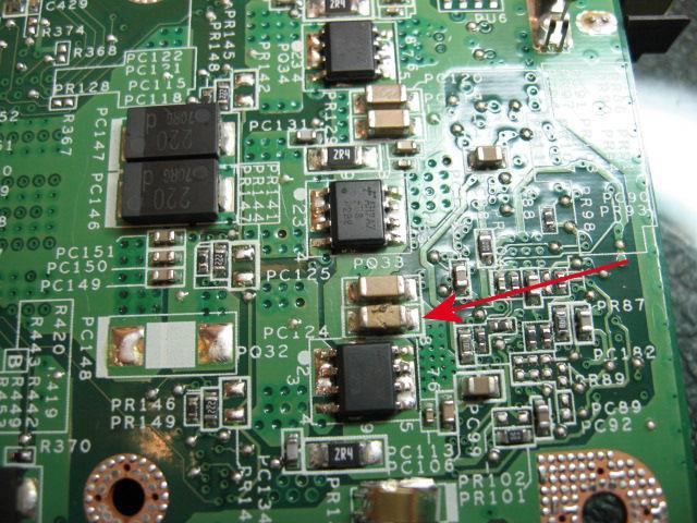
4 Applications of Inductor Power Transmission Lines and Utility Substation 3 Power Supply Tranceiver PCB Memory Control PCB
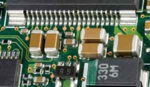
5 Circuit Symbol Inductor Basics Practical Inductor 4 An inductor opposes an abrupt change in the current through it (the voltage across an inductor can change abruptly) The ideal inductor does not dissipate energy. It takes power from the circuit when storing energy and delivers power to the circuit when returning previously stored energy A practical, non-ideal inductor has small resistive component, called winding resistance: it dissipates energy. A practical, non-ideal inductor also has small winding capacitance due to the capacitive coupling between the conducting coils. Parasitic resistor and inductor are ignored at low frequencies
![Inductor v L di dt Where L=inductance [H], i=current [A], v=voltage [V], t=time [s] 5 L Any conductor of electric current has inductive properties and may be regarded as an inductor In order to](/docs-images/77/76582102/images/6-0.jpg "enhance the inductive effect, a practical inductor is usually formed into a cylindrical coil with many turns of conducting wire N A l 2 where N=the number of turns, l=length, A=cross-sectional area,")
6 Inductor v L di dt Where L=inductance [H], i=current [A], v=voltage [V], t=time [s] 5 L Any conductor of electric current has inductive properties and may be regarded as an inductor In order to enhance the inductive effect, a practical inductor is usually formed into a cylindrical coil with many turns of conducting wire N A l 2 where N=the number of turns, l=length, A=cross-sectional area, μ=permeability of the core.
7 Example 6.1: Inductor Current-Voltage Characteristics 6 Q: Find and sketch the voltage across the inductor A: Method 1: Solve the inductor equation, Method 2: Simulate
8 Current in terms of Voltage Across the Inductor Example 6.2 (Omit) 7 Q: Find and sketch the inductor current A: Method 1: Solve the inductor equation, Method 2: Simulate
9 AP6.1a, c, g : Voltage, Current, Power, Energy in Inductor 8
10 Combining Inductors What is L eq for series and parallel combinations? 9
11 P6.22b: Series and Parallel Combination of Inductors 10
12 EE 1270: Introduction to Electric Circuits 11 Capacitor

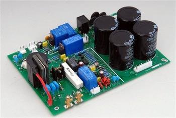
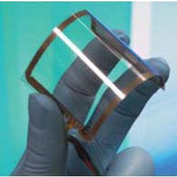
13 Store Charge in Circuits Applications of Capacitors 12 Welding Machine Power Filter Graphene based Flexible Supercapacitor Battery

 Applications of")
14 Power Factor Correction in Transmission Line (Ref) Applications of Capacitors AC Adapters 13


15 Tablets and Smart Phones Applications of Capacitors Capacitor Proximity Switch in Elevators 14
16 Circuit Symbol Capacitor Basics Practical Capacitor 15 A Capacitor opposes an abrupt change in the voltage across it (the current across a capacitor can change abruptly) The ideal capacitor takes power from the ciruit and stores the energy: we denote this operation as, "capacitor charges up..." A practical, nonideal capacitor has a small resistive component, called Equivalent Series Resistance (ESR): it discharges the cap. A practical, noideal inductor also has small Equivlent Series Inductance (ESL) due to the capacitive coupling between the capacitor leads or PCB traces or pads We ignore ESR and ESL at low frequencies


17 Ceramic Capacitor Capacitor Electrolytic Capacitor Surface Mount Capacitor 16 A capacitor consists of two conducting layers separated by dielectic material A capacitor is a passive element designed to store energy in its electric field Capacitance is the ratio of the charge on one plate of a capacitor to the voltage difference between the two plates (unit=farads or F)

![d=gap [m], q=charge accumulated on the plates, i=current across the capacitor Larger the area, higher the](/docs-images/77/76582102/images/18-1.jpg "capacitance * More info on dielectrics can be found at: http://hyperphysics.phy-astr.gsu.")
18 Capacitor Higher the dielectric* constant, higher the capacitance Smaller the gap, higher the capaictance A C ; d q CV dq dt i C dv dt 17 Where, C=capacitance [F], ε=dielectric constant [N/A 2 ], A=overlapping area [m 2 ], d=gap [m], q=charge accumulated on the plates, i=current across the capacitor Larger the area, higher the capacitance * More info on dielectrics can be found at:
19 AP 6.2 Voltage, Current, Power and Energy in a Capacitor 18 v 0... t 0 v 40e t sin(30000t)... t 0 1) Given the voltage find the capacitor current at t=0 2) Find the power delivered to the capacitor at t=π/80 ms 3) Find the energy stored in the capacitor at t=π/80 ms
20 Combining Capacitors What is C eq for series and parallel combinations? 19
21 P6.27: Series and Parallel Combination of Capacitors 20 Q: How do you combine two parallel caps with different voltages?
22 Always Remember!! An inductor will act as a short at DC (low frequency) and open at AC (high frequency) 21 low frequency high frequency A capacitor will act as an open at DC (low frequency) and short at AC (high frequency) low frequency high frequency
ENGR 2405 Chapter 6. Capacitors And Inductors
 ENGR 2405 Chapter 6 Capacitors And Inductors Overview This chapter will introduce two new linear circuit elements: The capacitor The inductor Unlike resistors, these elements do not dissipate energy They
ECE2262 Electric Circuits. Chapter 6: Capacitance and Inductance
 ECE2262 Electric Circuits Chapter 6: Capacitance and Inductance Capacitors Inductors Capacitor and Inductor Combinations Op-Amp Integrator and Op-Amp Differentiator 1 CAPACITANCE AND INDUCTANCE Introduces
CIRCUIT ELEMENT: CAPACITOR
 CIRCUIT ELEMENT: CAPACITOR PROF. SIRIPONG POTISUK ELEC 308 Types of Circuit Elements Two broad types of circuit elements Ati Active elements -capable of generating electric energy from nonelectric energy
ECE2262 Electric Circuits. Chapter 6: Capacitance and Inductance
 ECE2262 Electric Circuits Chapter 6: Capacitance and Inductance Capacitors Inductors Capacitor and Inductor Combinations 1 CAPACITANCE AND INDUCTANCE Introduces two passive, energy storing devices: Capacitors
Introduction to AC Circuits (Capacitors and Inductors)
") Introduction to AC Circuits (Capacitors and Inductors) Amin Electronics and Electrical Communications Engineering Department (EECE) Cairo University elc.n102.eng@gmail.com http://scholar.cu.edu.eg/refky/
Introduction to AC Circuits (Capacitors and Inductors) Amin Electronics and Electrical Communications Engineering Department (EECE) Cairo University elc.n102.eng@gmail.com http://scholar.cu.edu.eg/refky/
Electric Circuits I. Inductors. Dr. Firas Obeidat
 Electric Circuits I Inductors Dr. Firas Obeidat 1 Inductors An inductor is a passive element designed to store energy in its magnetic field. They are used in power supplies, transformers, radios, TVs,
Capacitors. Charging a Capacitor. Charge and Capacitance. L05: Capacitors and Inductors
 L05: Capacitors and Inductors 50 Capacitors 51 Outline of the lecture: Capacitors and capacitance. Energy storage. Capacitance formula. Types of capacitors. Inductors and inductance. Inductance formula.
Besides resistors, capacitors are one of the most common electronic components that you will encounter. Sometimes capacitors are components that one
 1 Besides resistors, capacitors are one of the most common electronic components that you will encounter. Sometimes capacitors are components that one would deliberately add to a circuit. Other times,
AP Physics C. Electric Circuits III.C
 AP Physics C Electric Circuits III.C III.C.1 Current, Resistance and Power The direction of conventional current Suppose the cross-sectional area of the conductor changes. If a conductor has no current,
ECE2262 Electric Circuit
 ECE2262 Electric Circuit Chapter 7: FIRST AND SECOND-ORDER RL AND RC CIRCUITS Response to First-Order RL and RC Circuits Response to Second-Order RL and RC Circuits 1 2 7.1. Introduction 3 4 In dc steady
LECTURE 8 RC AND RL FIRST-ORDER CIRCUITS (PART 1)
") CIRCUITS by Ulaby & Maharbiz LECTURE 8 RC AND RL FIRST-ORDER CIRCUITS (PART 1) 07/18/2013 ECE225 CIRCUIT ANALYSIS All rights reserved. Do not copy or distribute. 2013 National Technology and Science Press
CIRCUITS by Ulaby & Maharbiz LECTURE 8 RC AND RL FIRST-ORDER CIRCUITS (PART 1) 07/18/2013 ECE225 CIRCUIT ANALYSIS All rights reserved. Do not copy or distribute. 2013 National Technology and Science Press
Energy Storage Elements: Capacitors and Inductors
 CHAPTER 6 Energy Storage Elements: Capacitors and Inductors To this point in our study of electronic circuits, time has not been important. The analysis and designs we have performed so far have been static,
Pretest ELEA1831 Module 11 Units 1& 2 Inductance & Capacitance
 Pretest ELEA1831 Module 11 Units 1& 2 Inductance & Capacitance 1. What is Faraday s Law? Magnitude of voltage induced in a turn of wire is proportional to the rate of change of flux passing through that
2005 AP PHYSICS C: ELECTRICITY AND MAGNETISM FREE-RESPONSE QUESTIONS
 2005 AP PHYSICS C: ELECTRICITY AND MAGNETISM In the circuit shown above, resistors 1 and 2 of resistance R 1 and R 2, respectively, and an inductor of inductance L are connected to a battery of emf e and
A capacitor is a device that stores electric charge (memory devices). A capacitor is a device that stores energy E = Q2 2C = CV 2
. A capacitor is a device that stores energy E = Q2 2C = CV 2") Capacitance: Lecture 2: Resistors and Capacitors Capacitance (C) is defined as the ratio of charge (Q) to voltage (V) on an object: C = Q/V = Coulombs/Volt = Farad Capacitance of an object depends on geometry
Capacitance: Lecture 2: Resistors and Capacitors Capacitance (C) is defined as the ratio of charge (Q) to voltage (V) on an object: C = Q/V = Coulombs/Volt = Farad Capacitance of an object depends on geometry
Version 001 CIRCUITS holland (1290) 1
 1") Version CIRCUITS holland (9) This print-out should have questions Multiple-choice questions may continue on the next column or page find all choices before answering AP M 99 MC points The power dissipated
Version CIRCUITS holland (9) This print-out should have questions Multiple-choice questions may continue on the next column or page find all choices before answering AP M 99 MC points The power dissipated
Assessment Schedule 2015 Physics: Demonstrate understanding of electrical systems (91526)
") NCEA Level 3 Physics (91526) 2015 page 1 of 6 Assessment Schedule 2015 Physics: Demonstrate understanding of electrical systems (91526) Evidence Q Evidence Achievement Achievement with Merit Achievement
NCEA Level 3 Physics (91526) 2015 page 1 of 6 Assessment Schedule 2015 Physics: Demonstrate understanding of electrical systems (91526) Evidence Q Evidence Achievement Achievement with Merit Achievement
Slide 1 / 26. Inductance by Bryan Pflueger
 Slide 1 / 26 Inductance 2011 by Bryan Pflueger Slide 2 / 26 Mutual Inductance If two coils of wire are placed near each other and have a current passing through them, they will each induce an emf on one
Lecture 39. PHYC 161 Fall 2016
 Lecture 39 PHYC 161 Fall 016 Announcements DO THE ONLINE COURSE EVALUATIONS - response so far is < 8 % Magnetic field energy A resistor is a device in which energy is irrecoverably dissipated. By contrast,
Introduction to Electric Circuit Analysis
 EE110300 Practice of Electrical and Computer Engineering Lecture 2 and Lecture 4.1 Introduction to Electric Circuit Analysis Prof. Klaus Yung-Jane Hsu 2003/2/20 What Is An Electric Circuit? Electrical
Chapter 30. Inductance. PowerPoint Lectures for University Physics, 14th Edition Hugh D. Young and Roger A. Freedman Lectures by Jason Harlow
 Chapter 30 Inductance PowerPoint Lectures for University Physics, 14th Edition Hugh D. Young and Roger A. Freedman Lectures by Jason Harlow Learning Goals for Chapter 30 Looking forward at how a time-varying
P114 University of Rochester NAME S. Manly Spring 2010
 Exam 2 (March 23, 2010) Please read the problems carefully and answer them in the space provided. Write on the back of the page, if necessary. Show your work where indicated. Problem 1 ( 8 pts): In each
Handout 10: Inductance. Self-Inductance and inductors
 1 Handout 10: Inductance Self-Inductance and inductors In Fig. 1, electric current is present in an isolate circuit, setting up magnetic field that causes a magnetic flux through the circuit itself. This
CHAPTER 6. Inductance, Capacitance, and Mutual Inductance
 CHAPTER 6 Inductance, Capacitance, and Mutual Inductance 6.1 The Inductor Inductance is symbolized by the letter L, is measured in henrys (H), and is represented graphically as a coiled wire. The inductor
Module M2-1 Electrical Engineering
 Module M-1 Electrical Engineering TUTOIL 4 Topics Conductors (ต วนำไฟฟ า) Dielectrics or insulators (ฉนวนไฟฟ า) Capacitance CONDUCTOS ND DIELECTICS CPCITNCE SEPTEME 1, 016 fter this tutorial, you will
Chapter 21 Magnetic Induction Lecture 12
 Chapter 21 Magnetic Induction Lecture 12 21.1 Why is it called Electromagnetism? 21.2 Magnetic Flux and Faraday s Law 21.3 Lenz s Law and Work-Energy Principles 21.4 Inductance 21.5 RL Circuits 21.6 Energy
University Physics (PHY 2326)
") Chapter 25 University Physics (PHY 2326) Lecture 7 Electrostatics and electrodynamics Capacitance and capacitors capacitors with dielectrics Electric current current and drift speed resistance and Ohm
Chapter 25 University Physics (PHY 2326) Lecture 7 Electrostatics and electrodynamics Capacitance and capacitors capacitors with dielectrics Electric current current and drift speed resistance and Ohm
Chapter 28. Direct Current Circuits
 Chapter 28 Direct Current Circuits Circuit Analysis Simple electric circuits may contain batteries, resistors, and capacitors in various combinations. For some circuits, analysis may consist of combining
Physics 2B Spring 2010: Final Version A 1 COMMENTS AND REMINDERS:
 Physics 2B Spring 2010: Final Version A 1 COMMENTS AND REMINDERS: Closed book. No work needs to be shown for multiple-choice questions. 1. A charge of +4.0 C is placed at the origin. A charge of 3.0 C
CHAPTER FOUR MUTUAL INDUCTANCE
 CHAPTER FOUR MUTUAL INDUCTANCE 4.1 Inductance 4.2 Capacitance 4.3 Serial-Parallel Combination 4.4 Mutual Inductance 4.1 Inductance Inductance (L in Henry is the circuit parameter used to describe an inductor.
Solutions to these tests are available online in some places (but not all explanations are good)...
...") The Physics GRE Sample test put out by ETS https://www.ets.org/s/gre/pdf/practice_book_physics.pdf OSU physics website has lots of tips, and 4 additional tests http://www.physics.ohiostate.edu/undergrad/ugs_gre.php
The Physics GRE Sample test put out by ETS https://www.ets.org/s/gre/pdf/practice_book_physics.pdf OSU physics website has lots of tips, and 4 additional tests http://www.physics.ohiostate.edu/undergrad/ugs_gre.php
MAY/JUNE 2006 Question & Model Answer IN BASIC ELECTRICITY 194
 MAY/JUNE 2006 Question & Model Answer IN BASIC ELECTRICITY 194 Question 1 (a) List three sources of heat in soldering (b) state the functions of flux in soldering (c) briefly describe with aid of diagram
Inductors. Hydraulic analogy Duality with capacitor Charging and discharging. Lecture 12: Inductors
 Lecture 12: nductors nductors Hydraulic analogy Duality with capacitor Charging and discharging Robert R. McLeod, University of Colorado http://hilaroad.com/camp/projects/magnet.html 99 Lecture 12: nductors
Electromagnetic Induction (Chapters 31-32)
") Electromagnetic Induction (Chapters 31-3) The laws of emf induction: Faraday s and Lenz s laws Inductance Mutual inductance M Self inductance L. Inductors Magnetic field energy Simple inductive circuits
Electromagnetic Induction (Chapters 31-3) The laws of emf induction: Faraday s and Lenz s laws Inductance Mutual inductance M Self inductance L. Inductors Magnetic field energy Simple inductive circuits
Coulomb s constant k = 9x10 9 N m 2 /C 2
 1 Part 2: Electric Potential 2.1: Potential (Voltage) & Potential Energy q 2 Potential Energy of Point Charges Symbol U mks units [Joules = J] q 1 r Two point charges share an electric potential energy
Inductance, Inductors, RL Circuits & RC Circuits, LC, and RLC Circuits
 Inductance, Inductors, RL Circuits & RC Circuits, LC, and RLC Circuits Self-inductance A time-varying current in a circuit produces an induced emf opposing the emf that initially set up the timevarying
PHYS 1441 Section 001 Lecture #23 Monday, Dec. 4, 2017
 PHYS 1441 Section 1 Lecture #3 Monday, Dec. 4, 17 Chapter 3: Inductance Mutual and Self Inductance Energy Stored in Magnetic Field Alternating Current and AC Circuits AC Circuit W/ LRC Chapter 31: Maxwell
In addition to resistors that we have considered to date, there are two other basic electronic components that can be found everywhere: the capacitor
 In addition to resistors that we have considered to date, there are two other basic electronic components that can be found everywhere: the capacitor and the inductor. We will consider these two types
Inductance. Slide 2 / 26. Slide 1 / 26. Slide 4 / 26. Slide 3 / 26. Slide 6 / 26. Slide 5 / 26. Mutual Inductance. Mutual Inductance.
 Slide 1 / 26 Inductance 2011 by Bryan Pflueger Slide 2 / 26 Mutual Inductance If two coils of wire are placed near each other and have a current passing through them, they will each induce an emf on one
Circuit Analysis-II. Circuit Analysis-II Lecture # 5 Monday 23 rd April, 18
 Circuit Analysis-II Capacitors in AC Circuits Introduction ü The instantaneous capacitor current is equal to the capacitance times the instantaneous rate of change of the voltage across the capacitor.
PRACTICE EXAM 1 for Midterm 2
 PRACTICE EXAM 1 for Midterm 2 Multiple Choice Questions 1) The figure shows three identical lightbulbs connected to a battery having a constant voltage across its terminals. What happens to the brightness
REVIEW EXERCISES. 2. What is the resulting action if switch (S) is opened after the capacitor (C) is fully charged? Se figure 4.27.
 is opened after the capacitor (C) is fully charged? Se figure 4.27.") REVIEW EXERCISES Circle the letter of the correct answer to each question. 1. What is the current and voltage relationship immediately after the switch is closed in the circuit in figure 4-27, which shows
REVIEW EXERCISES Circle the letter of the correct answer to each question. 1. What is the current and voltage relationship immediately after the switch is closed in the circuit in figure 4-27, which shows
/20 /20 /20 /60. Dr. Galeazzi PHY207 Test #3 November 20, I.D. number:
 Signature: Name: I.D. number: You must do ALL the problems Each problem is worth 0 points for a total of 60 points. TO GET CREDIT IN PROBLEMS AND 3 YOU MUST SHOW GOOD WORK. CHECK DISCUSSION SECTION ATTENDED:
Objective of Lecture Discuss resistivity and the three categories of materials Chapter 2.1 Show the mathematical relationships between charge,
 Objective of Lecture Discuss resistivity and the three categories of materials Chapter 2.1 Show the mathematical relationships between charge, current, voltage, and energy. Chapter 2.2-2.4 Define resistance
Chapter 32. Inductance
 Chapter 32 Inductance Joseph Henry 1797 1878 American physicist First director of the Smithsonian Improved design of electromagnet Constructed one of the first motors Discovered self-inductance Unit of
Assessment Schedule 2016 Physics: Demonstrate understanding electrical systems (91526)
") NCEA evel 3 Physics (91526) 2016 page 1 of 5 Assessment Schedule 2016 Physics: Demonstrate understanding electrical systems (91526) Evidence Statement NØ N1 N 2 A 3 A 4 M 5 M 6 E 7 E 8 0 1A 2A 3A 4A or
NCEA evel 3 Physics (91526) 2016 page 1 of 5 Assessment Schedule 2016 Physics: Demonstrate understanding electrical systems (91526) Evidence Statement NØ N1 N 2 A 3 A 4 M 5 M 6 E 7 E 8 0 1A 2A 3A 4A or
P202 Practice Exam 2 Spring 2004 Instructor: Prof. Sinova
 P202 Practice Exam 2 Spring 2004 Instructor: Prof. Sinova Name: Date: (5)1. How many electrons flow through a battery that delivers a current of 3.0 A for 12 s? A) 4 B) 36 C) 4.8 10 15 D) 6.4 10 18 E)
General Physics II (PHYS 104) Exam 2: March 21, 2002
 Exam 2: March 21, 2002") General Physics II (PHYS 104) Exam 2: March 21, 2002 Name: Multiple Choice (3 points each): Answer the following multiple choice questions. Clearly circle the response (or responses) that provides the
General Physics II (PHYS 104) Exam 2: March 21, 2002 Name: Multiple Choice (3 points each): Answer the following multiple choice questions. Clearly circle the response (or responses) that provides the
[1] (b) Fig. 1.1 shows a circuit consisting of a resistor and a capacitor of capacitance 4.5 μf. Fig. 1.1
![[1] (b) Fig. 1.1 shows a circuit consisting of a resistor and a capacitor of capacitance 4.5 μf. Fig. 1.1](/thumbs/81/83276652.jpg "[1] (b) Fig. 1.1 shows a circuit consisting of a resistor and a capacitor of capacitance 4.5 μf. Fig. 1.1") 1 (a) Define capacitance..... [1] (b) Fig. 1.1 shows a circuit consisting of a resistor and a capacitor of capacitance 4.5 μf. S 1 S 2 6.3 V 4.5 μf Fig. 1.1 Switch S 1 is closed and switch S 2 is left
1 (a) Define capacitance..... [1] (b) Fig. 1.1 shows a circuit consisting of a resistor and a capacitor of capacitance 4.5 μf. S 1 S 2 6.3 V 4.5 μf Fig. 1.1 Switch S 1 is closed and switch S 2 is left
Chapter 30. Inductance
 Chapter 30 Inductance Self Inductance When a time dependent current passes through a coil, a changing magnetic flux is produced inside the coil and this in turn induces an emf in that same coil. This induced
Louisiana State University Physics 2102, Exam 2, March 5th, 2009.
 PRINT Your Name: Instructor: Louisiana State University Physics 2102, Exam 2, March 5th, 2009. Please be sure to PRINT your name and class instructor above. The test consists of 4 questions (multiple choice),
Induction_P1. 1. [1 mark]
![Induction_P1. 1. [1 mark]](/thumbs/88/115570773.jpg "Induction_P1. 1. [1 mark]") Induction_P1 1. [1 mark] Two identical circular coils are placed one below the other so that their planes are both horizontal. The top coil is connected to a cell and a switch. The switch is closed and
Induction_P1 1. [1 mark] Two identical circular coils are placed one below the other so that their planes are both horizontal. The top coil is connected to a cell and a switch. The switch is closed and
Inductance, RL Circuits, LC Circuits, RLC Circuits
 Inductance, R Circuits, C Circuits, RC Circuits Inductance What happens when we close the switch? The current flows What does the current look like as a function of time? Does it look like this? I t Inductance
Name:... Section:... Physics 208 Quiz 8. April 11, 2008; due April 18, 2008
 Name:... Section:... Problem 1 (6 Points) Physics 8 Quiz 8 April 11, 8; due April 18, 8 Consider the AC circuit consisting of an AC voltage in series with a coil of self-inductance,, and a capacitor of
AC Circuits III. Physics 2415 Lecture 24. Michael Fowler, UVa
 AC Circuits III Physics 415 Lecture 4 Michael Fowler, UVa Today s Topics LC circuits: analogy with mass on spring LCR circuits: damped oscillations LCR circuits with ac source: driven pendulum, resonance.
Self-inductance A time-varying current in a circuit produces an induced emf opposing the emf that initially set up the time-varying current.
 Inductance Self-inductance A time-varying current in a circuit produces an induced emf opposing the emf that initially set up the time-varying current. Basis of the electrical circuit element called an
Lecture 27: FRI 20 MAR
 Physics 2102 Jonathan Dowling Lecture 27: FRI 20 MAR Ch.30.7 9 Inductors & Inductance Nikolai Tesla Inductors: Solenoids Inductors are with respect to the magnetic field what capacitors are with respect
PES 1120 Spring 2014, Spendier Lecture 35/Page 1
 PES 0 Spring 04, Spendier Lecture 35/Page Today: chapter 3 - LC circuits We have explored the basic physics of electric and magnetic fields and how energy can be stored in capacitors and inductors. We
Basic RL and RC Circuits R-L TRANSIENTS: STORAGE CYCLE. Engineering Collage Electrical Engineering Dep. Dr. Ibrahim Aljubouri
 st Class Basic RL and RC Circuits The RL circuit with D.C (steady state) The inductor is short time at Calculate the inductor current for circuits shown below. I L E R A I L E R R 3 R R 3 I L I L R 3 R
Capacitance. A capacitor consists of two conductors that are close but not touching. A capacitor has the ability to store electric charge.
 Capacitance A capacitor consists of two conductors that are close but not touching. A capacitor has the ability to store electric charge. a) Parallel-plate capacitor connected to battery. (b) is a circuit
Chapter 2: Capacitor And Dielectrics
 hapter 2: apacitor And Dielectrics In this chapter, we are going to discuss the different ways that a capacitor could be arranged in a circuit and how its capacitance could be increased. Overview apacitor
PHYS 202 Notes, Week 6
 PHYS 202 Notes, Week 6 Greg Christian February 23 & 25, 2016 Last updated: 02/25/2016 at 12:36:40 This week we learn about electromagnetic induction. Magnetic Induction This section deals with magnetic
Capacitor Action. 3. Capacitor Action Theory Support. Electronics - AC Circuits
 Capacitor Action Topics covered in this presentation: Capacitors on DC Capacitors on AC Capacitor Charging Capacitor Discharging 1 of 18 Charging a Capacitor (DC) Before looking at how capacitors charge
Induction and inductance
 PH -C Fall 01 Induction and inductance Lecture 15 Chapter 30 (Halliday/Resnick/Walker, Fundamentals of Physics 8 th etion) 1 Chapter 30 Induction and Inductance In this chapter we will study the following
Mansfield Independent School District AP Physics C: Electricity and Magnetism Year at a Glance
 Mansfield Independent School District AP Physics C: Electricity and Magnetism Year at a Glance First Six-Weeks Second Six-Weeks Third Six-Weeks Lab safety Lab practices and ethical practices Math and Calculus
Physics 196 Final Test Point
 Physics 196 Final Test - 120 Point Name You need to complete six 5-point problems and six 10-point problems. Cross off one 5-point problem and one 10-point problem. 1. Two small silver spheres, each with
Capacitance, Resistance, DC Circuits
 This test covers capacitance, electrical current, resistance, emf, electrical power, Ohm s Law, Kirchhoff s Rules, and RC Circuits, with some problems requiring a knowledge of basic calculus. Part I. Multiple
Capacitor. Capacitor (Cont d)
") 1 2 1 Capacitor Capacitor is a passive two-terminal component storing the energy in an electric field charged by the voltage across the dielectric. Fixed Polarized Variable Capacitance is the ratio of
1 2 1 Capacitor Capacitor is a passive two-terminal component storing the energy in an electric field charged by the voltage across the dielectric. Fixed Polarized Variable Capacitance is the ratio of
Physics 405/505 Digital Electronics Techniques. University of Arizona Spring 2006 Prof. Erich W. Varnes
 Physics 405/505 Digital Electronics Techniques University of Arizona Spring 2006 Prof. Erich W. Varnes Administrative Matters Contacting me I will hold office hours on Tuesday from 1-3 pm Room 420K in
Active Figure 32.3 (SLIDESHOW MODE ONLY)
") RL Circuit, Analysis An RL circuit contains an inductor and a resistor When the switch is closed (at time t = 0), the current begins to increase At the same time, a back emf is induced in the inductor
RL Circuit, Analysis An RL circuit contains an inductor and a resistor When the switch is closed (at time t = 0), the current begins to increase At the same time, a back emf is induced in the inductor
EE292: Fundamentals of ECE
 EE292: Fundamentals of ECE Fall 2012 TTh 10:00-11:15 SEB 1242 Lecture 14 121011 http://www.ee.unlv.edu/~b1morris/ee292/ 2 Outline Review Steady-State Analysis RC Circuits RL Circuits 3 DC Steady-State
we can said that matter can be regarded as composed of three kinds of elementary particles; proton, neutron (no charge), and electron.
, and electron.") Physics II we can said that matter can be regarded as composed of three kinds of elementary particles; proton, neutron (no charge), and electron. Particle Symbol Charge (e) Mass (kg) Proton P +1 1.67
Physics II we can said that matter can be regarded as composed of three kinds of elementary particles; proton, neutron (no charge), and electron. Particle Symbol Charge (e) Mass (kg) Proton P +1 1.67
Basic Electronics. Introductory Lecture Course for. Technology and Instrumentation in Particle Physics Chicago, Illinois June 9-14, 2011
 Basic Electronics Introductory Lecture Course for Technology and Instrumentation in Particle Physics 2011 Chicago, Illinois June 9-14, 2011 Presented By Gary Drake Argonne National Laboratory drake@anl.gov
Chapter 30 Inductance and Electromagnetic Oscillations
 Chapter 30 Inductance and Electromagnetic Oscillations Units of Chapter 30 30.1 Mutual Inductance: 1 30.2 Self-Inductance: 2, 3, & 4 30.3 Energy Stored in a Magnetic Field: 5, 6, & 7 30.4 LR Circuit: 8,
Chapter 32. Inductance
 Chapter 32 Inductance Inductance Self-inductance A time-varying current in a circuit produces an induced emf opposing the emf that initially set up the time-varying current. Basis of the electrical circuit
Name: Class: Date: Multiple Choice Identify the letter of the choice that best completes the statement or answers the question.
 Name: Class: Date: AP REVIEW 4 Multiple Choice Identify the letter of the choice that best completes the statement or answers the question. 1. If a positively charged glass rod is used to charge a metal
The next two questions pertain to the situation described below. Consider a parallel plate capacitor with separation d:
 PHYS 102 Exams Exam 2 PRINT (A) The next two questions pertain to the situation described below. Consider a parallel plate capacitor with separation d: It is connected to a battery with constant emf V.
INDUCTANCE Self Inductance
 NDUTANE 3. Self nductance onsider the circuit shown in the Figure. When the switch is closed the current, and so the magnetic field, through the circuit increases from zero to a specific value. The increasing
PHY102 Electricity Course Summary
 TOPIC 1 ELECTOSTTICS PHY1 Electricity Course Summary Coulomb s Law The magnitude of the force between two point charges is directly proportional to the product of the charges and inversely proportional
What happens when things change. Transient current and voltage relationships in a simple resistive circuit.
 Module 4 AC Theory What happens when things change. What you'll learn in Module 4. 4.1 Resistors in DC Circuits Transient events in DC circuits. The difference between Ideal and Practical circuits Transient
EIT Review. Electrical Circuits DC Circuits. Lecturer: Russ Tatro. Presented by Tau Beta Pi The Engineering Honor Society 10/3/2006 1
 EIT Review Electrical Circuits DC Circuits Lecturer: Russ Tatro Presented by Tau Beta Pi The Engineering Honor Society 10/3/2006 1 Session Outline Basic Concepts Basic Laws Methods of Analysis Circuit
Lecture #3. Review: Power
 Lecture #3 OUTLINE Power calculations Circuit elements Voltage and current sources Electrical resistance (Ohm s law) Kirchhoff s laws Reading Chapter 2 Lecture 3, Slide 1 Review: Power If an element is
Capacitance. Chapter 21 Chapter 25. K = C / C o V = V o / K. 1 / Ceq = 1 / C / C 2. Ceq = C 1 + C 2
 = Chapter 21 Chapter 25 Capacitance K = C / C o V = V o / K 1 / Ceq = 1 / C 1 + 1 / C 2 Ceq = C 1 + C 2 Copyright 25-2 Capacitance 25.01 Sketch a schematic diagram of a circuit with a parallel-plate capacitor,
LR Circuits. . The voltage drop through both resistors will equal. Hence 10 1 A
 The diagram shows a classic R circuit, containing both resistors and inductors. The switch shown is initially connected to neither terminal, and is then thrown to position a at time t = 0. R Circuits E
Agenda for Today. Elements of Physics II. Capacitors Parallel-plate. Charging of capacitors
 Capacitors Parallel-plate Physics 132: Lecture e 7 Elements of Physics II Charging of capacitors Agenda for Today Combinations of capacitors Energy stored in a capacitor Dielectrics in capacitors Physics
r where the electric constant
 1.0 ELECTROSTATICS At the end of this topic, students will be able to: 10 1.1 Coulomb s law a) Explain the concepts of electrons, protons, charged objects, charged up, gaining charge, losing charge, charging
Lecture 20. March 22/24 th, Capacitance (Part I) Chapter , Pages
 Chapter , Pages") Lecture 0 March /4 th, 005 Capacitance (Part I) Reading: Boylestad s Circuit Analysis, 3 rd Canadian Edition Chapter 10.1-6, Pages 8-94 Assignment: Assignment #10 Due: March 31 st, 005 Preamble: Capacitance
Lecture 0 March /4 th, 005 Capacitance (Part I) Reading: Boylestad s Circuit Analysis, 3 rd Canadian Edition Chapter 10.1-6, Pages 8-94 Assignment: Assignment #10 Due: March 31 st, 005 Preamble: Capacitance
General Physics - E&M (PHY 1308) - Lecture Notes. General Physics - E&M (PHY 1308) Lecture Notes
 - Lecture Notes. General Physics - E&M (PHY 1308) Lecture Notes") General Physics - E&M (PHY 1308) Lecture Notes Lecture 021: Self-Inductance and Inductors SteveSekula, 12 April 2011 (created 7 November 2010) Goals of this Lecture no tags Understand "self-inductance"
General Physics - E&M (PHY 1308) Lecture Notes Lecture 021: Self-Inductance and Inductors SteveSekula, 12 April 2011 (created 7 November 2010) Goals of this Lecture no tags Understand "self-inductance"
Inductance, RL and RLC Circuits
 Inductance, RL and RLC Circuits Inductance Temporarily storage of energy by the magnetic field When the switch is closed, the current does not immediately reach its maximum value. Faraday s law of electromagnetic
Phys 2025, First Test. September 20, minutes Name:
 Phys 05, First Test. September 0, 011 50 minutes Name: Show all work for maximum credit. Each problem is worth 10 points. Work 10 of the 11 problems. k = 9.0 x 10 9 N m / C ε 0 = 8.85 x 10⁻¹ C / N m e
MEP 382: Design of Applied Measurement Systems Lecture 3: DC & AC Circuit Analysis
 Faculty of Engineering MEP 38: Design of Applied Measurement Systems Lecture 3: DC & AC Circuit Analysis Outline oltage and Current Ohm s Law Kirchoff s laws esistors Series and Parallel oltage Dividers
AP Physics C. Magnetism - Term 4
 AP Physics C Magnetism - Term 4 Interest Packet Term Introduction: AP Physics has been specifically designed to build on physics knowledge previously acquired for a more in depth understanding of the world
Physics 6B Summer 2007 Final
 Physics 6B Summer 2007 Final Question 1 An electron passes through two rectangular regions that contain uniform magnetic fields, B 1 and B 2. The field B 1 is stronger than the field B 2. Each field fills
Physics Investigation 10 Teacher Manual
 Physics Investigation 10 Teacher Manual Observation When a light bulb is connected to a number of charged capacitors, it lights up for different periods of time. Problem What does the rate of discharging
Alternating Current Circuits. Home Work Solutions
 Chapter 21 Alternating Current Circuits. Home Work s 21.1 Problem 21.11 What is the time constant of the circuit in Figure (21.19). 10 Ω 10 Ω 5.0 Ω 2.0µF 2.0µF 2.0µF 3.0µF Figure 21.19: Given: The circuit
Class 6. Capacitance and Capacitors. Physics 106. Winter Press CTRL-L to view as a slide show. Class 6. Physics 106.
 and in and Energy Winter 2018 Press CTRL-L to view as a slide show. From last time: The field lines are related to the field as follows: What is the electric potential? How are the electric field and the
Do not fill out the information below until instructed to do so! Name: Signature: Section Number:
 Do not fill out the information below until instructed to do so! Name: Signature: E-mail: Section Number: No calculators are allowed in the test. Be sure to put a box around your final answers and clearly
CAPACITANCE. Capacitor. Because of the effect of capacitance, an electrical circuit can store energy, even after being de-energized.
 D ircuits APAITANE APAITANE Because of the effect of capacitance, an electrical circuit can store energy, even after being de-energized. EO 1.5 EO 1.6 EO 1.7 EO 1.8 EO 1.9 DESRIBE the construction of a
Unit-2.0 Circuit Element Theory
 Unit2.0 Circuit Element Theory Dr. Anurag Srivastava Associate Professor ABVIIITM, Gwalior Circuit Theory Overview Of Circuit Theory; Lumped Circuit Elements; Topology Of Circuits; Resistors; KCL and KVL;
Experiment FT1: Measurement of Dielectric Constant
 Experiment FT1: Measurement of Dielectric Constant Name: ID: 1. Objective: (i) To measure the dielectric constant of paper and plastic film. (ii) To examine the energy storage capacity of a practical capacitor.