Introductory Circuit Analysis
|
|
|
- Henry Ball
- 6 years ago
- Views:
Transcription

1 Introductory Circuit Analysis CHAPTER 6 Parallel dc Circuits
2 OBJECTIVES Become familiar with the characteristics of a parallel network and how to solve for the voltage, current, and power to each element. Develop a clear understanding of Kirchhoff s current law and its importance to the analysis of electric circuits.
3 OBJECTIVES Become aware of how the source current will split between parallel elements and how to properly apply the current divider rule. Clearly understand the impact of open and short circuits on the behavior of a network.
4 OBJECTIVES Learn how to use an ohmmeter, voltmeter, and ammeter to measure the important parameters of a parallel network.
5 INTRODUCTION Two network configurations, series and parallel, form the framework for some of the most complex network structures. A clear understanding of each will pay enormous dividends as more complex methods and networks are examined.
6 PARALLEL RESISTORS The term parallel is used so often to describe a physical arrangement between two elements that most individuals are aware of its general characteristics. In general, two elements, branches, or circuits are in parallel if they have two points in common.
7 PARALLEL RESISTORS FIG. 6.1 (a) Parallel resistors; (b) R 1 and R 2 are in parallel; (c) R 3 is in parallel with the series combination of R 1 and R 2.
8 PARALLEL RESISTORS FIG. 6.2 Schematic representations of three parallel resistors.

9 PARALLEL RESISTORS
10 PARALLEL RESISTORS


11 FIG. 6.5 Parallel resistors for Example 6.2.
12

13 PARALLEL RESISTORS FIG. 6.6 Network to be investigated in Example 6.3.
14 FIG. 6.7 Network in Fig. 6.6 redrawn.

15 PARALLEL RESISTORS: Special Case- Equal Parallel Resistors
16
17
18
19 PARALLEL RESISTORS: Special Case- Two Parallel Resistors In the vast majority of cases, only two or three parallel resistors will have to be combined. With this in mind, an equation has been derived for two parallel resistors that is easy to apply and removes the need to continually worry about dividing into 1 and possibly misplacing a decimal point.
20 PARALLEL RESISTORS: Special Case- Two Parallel Resistors FIG Parallel network for Example 6.9. FIG Redrawn network in Fig (Example 6.9).


21 FIG Redrawn network in Fig (Example 6.9).

22 PARALLEL RESISTORS Instrumentation FIG Using an ohmmeter to measure the total resistance of a parallel network.
23 PARALLEL CIRCUITS A parallel circuit can now be established by connecting a supply across a set of parallel resistors as shown in Fig The positive terminal of the supply is directly connected to the top of each resistor, while the negative terminal is connected to the bottom of each resistor. FIG Parallel network.
24 PARALLEL CIRCUITS In general, the voltage is always the same across parallel elements. Therefore, remember that if two elements are in parallel, the voltage across them must be the same. However, if the voltage across two neighboring elements is the same, the two elements may or may not be in parallel.


25 PARALLEL CIRCUITS FIG Replacing the parallel resistors in Fig with the equivalent total resistance. FIG Mechanical analogy for Fig
26 PARALLEL CIRCUITS For single-source parallel networks, the source current (Is) is always equal to the sum of the individual branch currents. FIG Demonstrating the duality that exists between series and parallel circuits.

27 FIG Parallel network for Example 6.12.
28
29

30 PARALLEL CIRCUITS Instrumentation FIG Measuring the voltages of a parallel dc network.

31 PARALLEL CIRCUITS Instrumentation FIG Measuring the source current of a parallel network.
32 PARALLEL CIRCUITS Instrumentation FIG Measuring the current through resistor R 1.
33 POWER DISTRIBUTION IN A PARALLEL CIRCUIT Recall from the discussion of series circuits that the power applied to a series resistive circuit equals the power dissipated by the resistive elements. The same is true for parallel resistive networks. In fact, for any network composed of resistive elements, the power applied by the battery will equal that dissipated by the resistive elements.

34 POWER DISTRIBUTION IN A PARALLEL CIRCUIT FIG Power flow in a dc parallel network.
35 POWER DISTRIBUTION IN A PARALLEL CIRCUIT
36
37
38
39 KIRCHHOFF S CURRENT LAW In the previous chapter, Kirchhoff s voltage law was introduced, providing a very important relationship among the voltages of a closed path.
40 KIRCHHOFF S CURRENT LAW Kirchhoff is also credited with developing the following equally important relationship between the currents of a network, called Kirchhoff s current law (KCL): The algebraic sum of the currents entering and leaving a junction (or region) of a network is zero.
41 KIRCHHOFF S CURRENT LAW FIG Introducing Kirchhoff s current law.
 Demonstrating Kirchhoff s current law; (b) the water")
42 KIRCHHOFF S CURRENT LAW FIG (a) Demonstrating Kirchhoff s current law; (b) the water analogy for the junction in (a).

43 KIRCHHOFF S CURRENT LAW In technology, the term node is commonly used to refer to a junction of two or more branches. FIG Two-node configuration for Example 6.16.

44 KIRCHHOFF S CURRENT LAW FIG Four-node configuration for Example 6.17.
45 KIRCHHOFF S CURRENT LAW FIG Network for Example 6.18.

46 KIRCHHOFF S CURRENT LAW
47
48
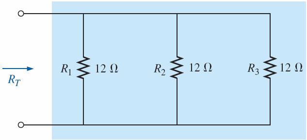
49 CURRENT DIVIDER RULE For series circuits we have the powerful voltage divider rule for finding the voltage across a resistor in a series circuit. We now introduce the equally powerful current divider rule (CDR) for finding the current through a resistor in a parallel circuit.
50 CURRENT DIVIDER RULE In general: For two parallel elements of equal value, the current will divide equally. For parallel elements with different values, the smaller the resistance, the greater is the share of input current. For parallel elements of different values, the current will split with a ratio equal to the inverse of their resistance values.
51 RATIO RULE

52 CURRENT DIVIDER RULE
53
54
55 CURRENT DIVIDER RULE FIG Deriving the current divider rule: (a) parallel network of N parallel resistors; (b) reduced equivalent of part (a).
56
57 CURRENT DIVIDER RULE For parallel network above, determine current I1 using CDR.
58
59 CURRENT DIVIDER RULE Note also that for a parallel network, the current through the smallest resistor will be very close to the total entering current if the other parallel elements of the configuration are much larger in magnitude.
60 CURRENT DIVIDER RULE: Special Case- Two Parallel Resistors FIG Deriving the current divider rule for the special case of only two parallel resistors.
61
62
63 CURRENT DIVIDER RULE: Special Case- Two Parallel Resistors FIG Demonstrating how current divides through equal and unequal parallel resistors.
64 VOLTAGE SOURCES IN PARALLEL Because the voltage is the same across parallel elements, voltage sources can be placed in parallel only if they have the same voltage. The primary reason for placing two or more batteries or supplies in parallel is to increase the current rating above that of a single supply.
Chapter 2. Engr228 Circuit Analysis. Dr Curtis Nelson
 Chapter 2 Engr228 Circuit Analysis Dr Curtis Nelson Chapter 2 Objectives Understand symbols and behavior of the following circuit elements: Independent voltage and current sources; Dependent voltage and
Note-A-Rific: Kirchhoff s
 Note-A-Rific: Kirchhoff s We sometimes encounter a circuit that is too complicated for simple analysis. Maybe there is a mix of series and parallel, or more than one power source. To deal with such complicated
Sirindhorn International Institute of Technology Thammasat University at Rangsit
 Sirindhorn International Institute of Technology Thammasat University at Rangsit School of Information, Computer and Communication Technology COURSE : ECS 304 Basic Electrical Engineering Lab INSTRUCTOR
Direct Current Circuits. February 18, 2014 Physics for Scientists & Engineers 2, Chapter 26 1
 Direct Current Circuits February 18, 2014 Physics for Scientists & Engineers 2, Chapter 26 1 Kirchhoff s Junction Rule! The sum of the currents entering a junction must equal the sum of the currents leaving
Electricity & Magnetism
 Electricity & Magnetism D.C. Circuits Marline Kurishingal Note : This chapter includes only D.C. In AS syllabus A.C is not included. Recap... Electrical Circuit Symbols : Draw and interpret circuit diagrams
Module 2. DC Circuit. Version 2 EE IIT, Kharagpur
 Module 2 DC Circuit Lesson 5 Node-voltage analysis of resistive circuit in the context of dc voltages and currents Objectives To provide a powerful but simple circuit analysis tool based on Kirchhoff s
ECE 1311: Electric Circuits. Chapter 2: Basic laws
 ECE 1311: Electric Circuits Chapter 2: Basic laws Basic Law Overview Ideal sources series and parallel Ohm s law Definitions open circuits, short circuits, conductance, nodes, branches, loops Kirchhoff's
Review of Ohm's Law: The potential drop across a resistor is given by Ohm's Law: V= IR where I is the current and R is the resistance.
 DC Circuits Objectives The objectives of this lab are: 1) to construct an Ohmmeter (a device that measures resistance) using our knowledge of Ohm's Law. 2) to determine an unknown resistance using our
Voltage Dividers, Nodal, and Mesh Analysis
 Engr228 Lab #2 Voltage Dividers, Nodal, and Mesh Analysis Name Partner(s) Grade /10 Introduction This lab exercise is designed to further your understanding of the use of the lab equipment and to verify
DC CIRCUIT ANALYSIS. Loop Equations
 All of the rules governing DC circuits that have been discussed so far can now be applied to analyze complex DC circuits. To apply these rules effectively, loop equations, node equations, and equivalent
EXPERIMENT 12 OHM S LAW
 EXPERIMENT 12 OHM S LAW INTRODUCTION: We will study electricity as a flow of electric charge, sometimes making analogies to the flow of water through a pipe. In order for electric charge to flow a complete
PHYSICS 171. Experiment 3. Kirchhoff's Laws. Three resistors (Nominally: 1 Kilohm, 2 Kilohm, 3 Kilohm).
.") PHYSICS 171 Experiment 3 Kirchhoff's Laws Equipment: Supplies: Digital Multimeter, Power Supply (0-20 V.). Three resistors (Nominally: 1 Kilohm, 2 Kilohm, 3 Kilohm). A. Kirchhoff's Loop Law Suppose that
PHYSICS 171 Experiment 3 Kirchhoff's Laws Equipment: Supplies: Digital Multimeter, Power Supply (0-20 V.). Three resistors (Nominally: 1 Kilohm, 2 Kilohm, 3 Kilohm). A. Kirchhoff's Loop Law Suppose that
Chapter 28. Direct Current Circuits
 Chapter 28 Direct Current Circuits Circuit Analysis Simple electric circuits may contain batteries, resistors, and capacitors in various combinations. For some circuits, analysis may consist of combining
Parallel Circuits. Chapter
 Chapter 5 Parallel Circuits Topics Covered in Chapter 5 5-1: The Applied Voltage V A Is the Same Across Parallel Branches 5-2: Each Branch I Equals V A / R 5-3: Kirchhoff s Current Law (KCL) 5-4: Resistance
Topic 5.2 Heating Effect of Electric Currents
 Topic 5.2 Heating Effect of Electric Currents Kari Eloranta 2017 Jyväskylän Lyseon lukio International Baccalaureate February 14, 2017 Topic 5.2 Heating Effect of Electric Currents In subtopic 5.2 we study
Kirchhoff's Laws and Circuit Analysis (EC 2)
") Kirchhoff's Laws and Circuit Analysis (EC ) Circuit analysis: solving for I and V at each element Linear circuits: involve resistors, capacitors, inductors Initial analysis uses only resistors Power sources,
Kirchhoff's Laws and Circuit Analysis (EC ) Circuit analysis: solving for I and V at each element Linear circuits: involve resistors, capacitors, inductors Initial analysis uses only resistors Power sources,
ES250: Electrical Science. HW1: Electric Circuit Variables, Elements and Kirchhoff s Laws
 ES250: Electrical Science HW1: Electric Circuit Variables, Elements and Kirchhoff s Laws Introduction Engineers use electric circuits to solve problems that are important to modern society, such as: 1.
R 2, R 3, and R 4 are in parallel, R T = R 1 + (R 2 //R 3 //R 4 ) + R 5. C-C Tsai
 + R 5. C-C Tsai") Chapter 07 Series-Parallel Circuits The Series-Parallel Network Complex circuits May be separated both series and/or parallel elements Combinations which are neither series nor parallel To analyze a circuit
Chapter 07 Series-Parallel Circuits The Series-Parallel Network Complex circuits May be separated both series and/or parallel elements Combinations which are neither series nor parallel To analyze a circuit
Experiment 4: Resistances in Circuits
 Name: Partners: Date: Experiment 4: Resistances in Circuits EQUIPMENT NEEDED: Circuits Experiment Board Multimeter Resistors Purpose The purpose of this lab is to begin experimenting with the variables
Circuits Practice Websheet 18.1
 Circuits Practice Websheet 18.1 Multiple Choice Identify the choice that best completes the statement or answers the question. 1. How much power is being dissipated by one of the 10-Ω resistors? a. 24
Lecture Notes on DC Network Theory
 Federal University, Ndufu-Alike, Ikwo Department of Electrical/Electronics and Computer Engineering (ECE) Faculty of Engineering and Technology Lecture Notes on DC Network Theory Harmattan Semester by
UNIT 4 DC EQUIVALENT CIRCUIT AND NETWORK THEOREMS
 UNIT 4 DC EQUIVALENT CIRCUIT AND NETWORK THEOREMS 1.0 Kirchoff s Law Kirchoff s Current Law (KCL) states at any junction in an electric circuit the total current flowing towards that junction is equal
Discussion Question 6A
 Discussion Question 6 P212, Week 6 Two Methods for Circuit nalysis Method 1: Progressive collapsing of circuit elements In last week s discussion, we learned how to analyse circuits involving batteries
Exercise 2: Millman s Theorem
 Exercise 2: Millman s Theorem EXERCISE OBJECTIVE When you have completed this exercise, you will be able to solve a circuit by applying Millman s theorem. You will verify your results by comparing calculated
ANNOUNCEMENT ANNOUNCEMENT
 ANNOUNCEMENT Exam : Tuesday September 25, 208, 8 PM - 0 PM Location: Elliott Hall of Music (see seating chart) Covers all readings, lectures, homework from Chapters 2 through 23 Multiple choice (5-8 questions)
Chapter 5. Department of Mechanical Engineering
 Source Transformation By KVL: V s =ir s + v By KCL: i s =i + v/r p is=v s /R s R s =R p V s /R s =i + v/r s i s =i + v/r p Two circuits have the same terminal voltage and current Source Transformation
Name Date Time to Complete. NOTE: The multimeter s 10 AMP range, instead of the 300 ma range, should be used for all current measurements.
 Name Date Time to Complete h m Partner Course/ Section / Grade Complex Circuits In this laboratory you will continue your exploration of dc electric circuits with a steady current. The circuits will be
Name Date Time to Complete
 Name Date Time to Complete h m Partner Course/ Section / Grade Complex Circuits In this laboratory you will connect electric lamps together in a variety of circuits. The purpose of these exercises is to
Chapter 26 Direct-Current and Circuits. - Resistors in Series and Parallel - Kirchhoff s Rules - Electric Measuring Instruments - R-C Circuits
 Chapter 26 Direct-Current and Circuits - esistors in Series and Parallel - Kirchhoff s ules - Electric Measuring Instruments - -C Circuits . esistors in Series and Parallel esistors in Series: V ax I V
Designing Information Devices and Systems I Fall 2018 Lecture Notes Note Resistive Touchscreen - expanding the model
 EECS 16A Designing Information Devices and Systems I Fall 2018 Lecture Notes Note 13 13.1 Resistive Touchscreen - expanding the model Recall the physical structure of the simple resistive touchscreen given
In this unit, we will examine the movement of electrons, which we call CURRENT ELECTRICITY.
 Recall: Chemistry and the Atom! What are the 3 subatomic Where are they found in the particles? atom? What electric charges do they have? How was a positive ion created? How was a negative ion created?
Series & Parallel Resistors 3/17/2015 1
 Series & Parallel Resistors 3/17/2015 1 Series Resistors & Voltage Division Consider the single-loop circuit as shown in figure. The two resistors are in series, since the same current i flows in both
Physics 102 Lab 4: Circuit Algebra and Effective Resistance Dr. Timothy C. Black Spring, 2005
 Physics 02 Lab 4: Circuit Algebra and Effective Resistance Dr. Timothy C. Black Spring, 2005 Theoretical Discussion The Junction Rule: Since charge is conserved, charge is neither created or destroyed
SIMPLE D.C. CIRCUITS AND MEASUREMENTS Background
 SIMPLE D.C. CICUITS AND MEASUEMENTSBackground This unit will discuss simple D.C. (direct current current in only one direction) circuits: The elements in them, the simple arrangements of these elements,
Multiloop DC Circuits (Kirchhoff s Rules)
") Multiloop DC Circuits (Kirchhoff s Rules) In analyzing circuits, it is generally the current that is of interest. You have seen how Ohm s Law can be used to analyze very simple circuits consisting of an
Multiloop DC Circuits (Kirchhoff s Rules) In analyzing circuits, it is generally the current that is of interest. You have seen how Ohm s Law can be used to analyze very simple circuits consisting of an
resistance in the circuit. When voltage and current values are known, apply Ohm s law to determine circuit resistance. R = E/I ( )
") DC Fundamentals Ohm s Law Exercise 1: Ohm s Law Circuit Resistance EXERCISE OBJECTIVE When you have completed this exercise, you will be able to determine resistance by using Ohm s law. You will verify
DC Fundamentals Ohm s Law Exercise 1: Ohm s Law Circuit Resistance EXERCISE OBJECTIVE When you have completed this exercise, you will be able to determine resistance by using Ohm s law. You will verify
Chapter 7. Chapter 7
 Chapter 7 Combination circuits Most practical circuits have combinations of series and parallel components. You can frequently simplify analysis by combining series and parallel components. An important
AC Circuit Analysis and Measurement Lab Assignment 8
 Electric Circuit Lab Assignments elcirc_lab87.fm - 1 AC Circuit Analysis and Measurement Lab Assignment 8 Introduction When analyzing an electric circuit that contains reactive components, inductors and
Industrial Electricity
 Industrial Electricity PRELAB / LAB 7: Series & Parallel Circuits with Faults Name PRELAB due BEFORE beginning the lab (initials required at the bottom of page 3) PLEASE TAKE THE TIME TO READ THIS PAGE
EXPERIMENT THREE DC CIRCUITS
 EXEMET THEE DC CCUT EQUMET EEDED: ) DC ower upply ) DMM 3) esistors 4) EL THEOY Kirchhoff's Laws: Kirchhoff's oltage Law: The algebraic sum of the voltages around any closed path is zero. v i i 0 3. Kirchhoff's
R R V I R. Conventional Current. Ohms Law V = IR
 DC Circuits opics EMF and erminal oltage esistors in Series and in Parallel Kirchhoff s ules EMFs in Series and in Parallel Capacitors in Series and in Parallel Ammeters and oltmeters Conventional Current
Electric Circuits I. Nodal Analysis. Dr. Firas Obeidat
 Electric Circuits I Nodal Analysis Dr. Firas Obeidat 1 Nodal Analysis Without Voltage Source Nodal analysis, which is based on a systematic application of Kirchhoff s current law (KCL). A node is defined
Lecture Outline Chapter 21. Physics, 4 th Edition James S. Walker. Copyright 2010 Pearson Education, Inc.
 Lecture Outline Chapter 21 Physics, 4 th Edition James S. Walker Chapter 21 Electric Current and Direct- Current Circuits Units of Chapter 21 Electric Current Resistance and Ohm s Law Energy and Power
D C Circuit Analysis and Network Theorems:
 UNIT-1 D C Circuit Analysis and Network Theorems: Circuit Concepts: Concepts of network, Active and passive elements, voltage and current sources, source transformation, unilateral and bilateral elements,
Ch 28-DC Circuits! 1.) EMF & Terminal Voltage! 9.0 V 8.7 V 8.7 V. V =! " Ir. Terminal Open circuit internal! voltage voltage (emf) resistance" 2.
 EMF & Terminal Voltage! 9.0 V 8.7 V 8.7 V. V =! Ir. Terminal Open circuit internal! voltage voltage (emf) resistance 2.") Ch 28-DC Circuits! 1.) EMF & Terminal Voltage! 9.0 V 8.7 V 8.7 V V =! " Ir Terminal Open circuit internal! voltage voltage (emf) resistance" 2.) Resistors in series! One of the bits of nastiness about
Ch 28-DC Circuits! 1.) EMF & Terminal Voltage! 9.0 V 8.7 V 8.7 V V =! " Ir Terminal Open circuit internal! voltage voltage (emf) resistance" 2.) Resistors in series! One of the bits of nastiness about
Clicker Session Currents, DC Circuits
 Clicker Session Currents, DC Circuits Wires A wire of resistance R is stretched uniformly (keeping its volume constant) until it is twice its original length. What happens to the resistance? 1) it decreases
Parallel Resistors (32.6)
") Parallel Resistors (32.6) Resistors connected at both ends are called parallel resistors Neil Alberding (SFU Physics) Physics 121: Optics, Electricity & Magnetism Spring 2010 1 / 1 Parallel Resistors (32.6)
Parallel Resistors (32.6) Resistors connected at both ends are called parallel resistors Neil Alberding (SFU Physics) Physics 121: Optics, Electricity & Magnetism Spring 2010 1 / 1 Parallel Resistors (32.6)
Chapter 18 Electric Currents
 Chapter 18 Electric Currents 1 The Electric Battery Volta discovered that electricity could be created if dissimilar metals were connected by a conductive solution called an electrolyte. This is a simple
RESISTANCE AND NETWORKS
 PURPOSE The purpose of this laboratory is to learn to construct simple circuits; and, to become familiar with the use of power supplies and the digital multimeter. to experimentally find the equivalent
Parallel Resistors (32.6)
") Parallel Resistors (32.6) Resistors connected at both ends are called parallel resistors The important thing to note is that: the two left ends of the resistors are at the same potential. Also, the two
Parallel Resistors (32.6) Resistors connected at both ends are called parallel resistors The important thing to note is that: the two left ends of the resistors are at the same potential. Also, the two
AP Physics C. Electric Circuits III.C
 AP Physics C Electric Circuits III.C III.C.1 Current, Resistance and Power The direction of conventional current Suppose the cross-sectional area of the conductor changes. If a conductor has no current,
mywbut.com Mesh Analysis
 Mesh Analysis 1 Objectives Meaning of circuit analysis; distinguish between the terms mesh and loop. To provide more general and powerful circuit analysis tool based on Kirchhoff s voltage law (KVL) only.
Engineering Fundamentals and Problem Solving, 6e
 Engineering Fundamentals and Problem Solving, 6e Chapter 17 Electrical Circuits Chapter Objectives Compute the equivalent resistance of resistors in series and in parallel Apply Ohm s law to a resistive
A Review of Circuitry
 1 A Review of Circuitry There is an attractive force between a positive and a negative charge. In order to separate these charges, a force at least equal to the attractive force must be applied to one
Physics 1214 Chapter 19: Current, Resistance, and Direct-Current Circuits
 Physics 1214 Chapter 19: Current, Resistance, and Direct-Current Circuits 1 Current current: (also called electric current) is an motion of charge from one region of a conductor to another. Current When
DC Circuit Analysis + 1 R 3 = 1 R R 2
 DC Circuit Analysis In analyzing circuits, it is generally the current that is of interest. You have seen how Ohm s Law can be used to analyze very simple circuits consisting of an EMF and single resistance.
Experiment 2: Analysis and Measurement of Resistive Circuit Parameters
 Experiment 2: Analysis and Measurement of Resistive Circuit Parameters Report Due In-class on Wed., Mar. 28, 2018 Pre-lab must be completed prior to lab. 1.0 PURPOSE To (i) verify Kirchhoff's laws experimentally;
M. C. Escher: Waterfall. 18/9/2015 [tsl425 1/29]
![M. C. Escher: Waterfall. 18/9/2015 [tsl425 1/29]](/thumbs/76/73138710.jpg "M. C. Escher: Waterfall. 18/9/2015 [tsl425 1/29]") M. C. Escher: Waterfall 18/9/2015 [tsl425 1/29] Direct Current Circuit Consider a wire with resistance R = ρl/a connected to a battery. Resistor rule: In the direction of I across a resistor with resistance
M. C. Escher: Waterfall 18/9/2015 [tsl425 1/29] Direct Current Circuit Consider a wire with resistance R = ρl/a connected to a battery. Resistor rule: In the direction of I across a resistor with resistance
DC STEADY STATE CIRCUIT ANALYSIS
 DC STEADY STATE CIRCUIT ANALYSIS 1. Introduction The basic quantities in electric circuits are current, voltage and resistance. They are related with Ohm s law. For a passive branch the current is: I=
Trade of Electrician. Resistance Network Measurement
 Trade of Electrician Standards Based Apprenticeship Resistance Network Measurement Phase 2 Module No. 2.1 Unit No. 2.1.5 COURSE NOTES Created by Gerry Ryan - Galway TC Revision 1. April 2000 by Gerry Ryan
Chapter 26 Direct-Current Circuits
 Chapter 26 Direct-Current Circuits 1 Resistors in Series and Parallel In this chapter we introduce the reduction of resistor networks into an equivalent resistor R eq. We also develop a method for analyzing
Physics Circuits: Series
 FACULTY OF EDUCATION Department of Curriculum and Pedagogy Physics Circuits: Series Science and Mathematics Education Research Group Supported by UBC Teaching and Learning Enhancement Fund 2012-2013 Series
Tutorial #4: Bias Point Analysis in Multisim
 SCHOOL OF ENGINEERING AND APPLIED SCIENCE DEPARTMENT OF ELECTRICAL AND COMPUTER ENGINEERING ECE 2115: ENGINEERING ELECTRONICS LABORATORY Tutorial #4: Bias Point Analysis in Multisim INTRODUCTION When BJTs
Notes on Electricity (Circuits)
") A circuit is defined to be a collection of energy-givers (batteries) and energy-takers (resistors, light bulbs, radios, etc.) that form a closed path (or complete path) through which electrical current
A circuit is defined to be a collection of energy-givers (batteries) and energy-takers (resistors, light bulbs, radios, etc.) that form a closed path (or complete path) through which electrical current
Lecture #3. Review: Power
 Lecture #3 OUTLINE Power calculations Circuit elements Voltage and current sources Electrical resistance (Ohm s law) Kirchhoff s laws Reading Chapter 2 Lecture 3, Slide 1 Review: Power If an element is
Electrical Circuits. Winchester College Physics. makptb. c D. Common Time man. 3rd year Revision Test
 Name... Set... Don.... manner~ man makptb Winchester College Physics 3rd year Revision Test Electrical Circuits Common Time 2011 Mark multiple choice answers with a cross (X) using the box below. I A B
Chapter 21 Electric Current and Direct- Current Circuits
 Chapter 21 Electric Current and Direct- Current Circuits Units of Chapter 21 Electric Current Resistance and Ohm s Law Energy and Power in Electric Circuits Resistors in Series and Parallel Kirchhoff s
ConcepTest PowerPoints
 ConcepTest PowerPoints Chapter 19 Physics: Principles with Applications, 6 th edition Giancoli 2005 Pearson Prentice Hall This work is protected by United States copyright laws and is provided solely for
Chapter 6 DIRECT CURRENT CIRCUITS. Recommended Problems: 6,9,11,13,14,15,16,19,20,21,24,25,26,28,29,30,31,33,37,68,71.
 Chapter 6 DRECT CURRENT CRCUTS Recommended Problems: 6,9,,3,4,5,6,9,0,,4,5,6,8,9,30,3,33,37,68,7. RESSTORS N SERES AND N PARALLEL - N SERES When two resistors are connected together as shown we said that
ELECTRICAL THEORY. Ideal Basic Circuit Element
 ELECTRICAL THEORY PROF. SIRIPONG POTISUK ELEC 106 Ideal Basic Circuit Element Has only two terminals which are points of connection to other circuit components Can be described mathematically in terms
Physics 7B-1 (A/B) Professor Cebra. Winter 2010 Lecture 2. Simple Circuits. Slide 1 of 20
 Professor Cebra. Winter 2010 Lecture 2. Simple Circuits. Slide 1 of 20") Physics 7B-1 (A/B) Professor Cebra Winter 2010 Lecture 2 Simple Circuits Slide 1 of 20 Conservation of Energy Density In the First lecture, we started with energy conservation. We divided by volume (making
Physics 7B-1 (A/B) Professor Cebra Winter 2010 Lecture 2 Simple Circuits Slide 1 of 20 Conservation of Energy Density In the First lecture, we started with energy conservation. We divided by volume (making
INTRODUCTION TO ELECTRONICS
 INTRODUCTION TO ELECTRONICS Basic Quantities Voltage (symbol V) is the measure of electrical potential difference. It is measured in units of Volts, abbreviated V. The example below shows several ways
Review of Circuit Analysis
 Review of Circuit Analysis Fundamental elements Wire Resistor Voltage Source Current Source Kirchhoff s Voltage and Current Laws Resistors in Series Voltage Division EE 42 Lecture 2 1 Voltage and Current
ELECTRIC CURRENTS D R M A R T A S T A S I A K D E P A R T M E N T O F C Y T O B I O L O G Y A N D P R O T E O M I C S
 ELECTRIC CURRENTS D R M A R T A S T A S I A K D E P A R T M E N T O F C Y T O B I O L O G Y A N D P R O T E O M I C S lecture based on 2016 Pearson Education, Ltd. The Electric Battery Electric Current
Outline. Week 5: Circuits. Course Notes: 3.5. Goals: Use linear algebra to determine voltage drops and branch currents.
 Outline Week 5: Circuits Course Notes: 3.5 Goals: Use linear algebra to determine voltage drops and branch currents. Components in Resistor Networks voltage source current source resistor Components in
Chapter 26 Direct-Current Circuits
 Chapter 26 Direct-Current Circuits 1 Resistors in Series and Parallel In this chapter we introduce the reduction of resistor networks into an equivalent resistor R eq. We also develop a method for analyzing
Notes on Electricity (Circuits)
") A circuit is defined to be a collection of energy-givers (active elements) and energy-takers (passive elements) that form a closed path (or complete path) through which electrical current can flow. The
A circuit is defined to be a collection of energy-givers (active elements) and energy-takers (passive elements) that form a closed path (or complete path) through which electrical current can flow. The
COE. DC. Challenging MCQ questions by The Physics Cafe. Compiled and selected by The Physics Cafe
 COE. DC Challenging MCQ questions by The Physics Cafe Compiled and selected by The Physics Cafe 1 battery of internal resistance r and e.m.f. E can supply a current of 6.0 to a resistor R as shown in Fig
ConcepTest Clicker Questions. Chapter 26 Physics: for Scientists & Engineers with Modern Physics, 4th edition Giancoli
 ConcepTest Clicker Questions Chapter 26 Physics: for Scientists & Engineers with Modern Physics, 4th edition Giancoli 2008 Pearson Education, Inc. This work is protected by United States copyright laws
STEP-UP 2011 Lesson Plan: Capacitance Brian Heglund Etowah High School Advisor: Phil First
 STEP-UP 2011 Lesson Plan: Capacitance Brian Heglund Etowah High School Advisor: Phil First Ultra High Vacuum (UHV) at GT can analyze sample surfaces with Leed and Auger. Problem: Can this wire be used
Chapter 7 Direct-Current Circuits
 Chapter 7 Direct-Current Circuits 7. Introduction... 7. Electromotive Force... 7.3 Resistors in Series and in Parallel... 4 7.4 Kirchhoff s Circuit Rules... 6 7.5 Voltage-Current Measurements... 8 7.6
Electric Currents and Circuits
 Nicholas J. Giordano www.cengage.com/physics/giordano Chapter 19 Electric Currents and Circuits Marilyn Akins, PhD Broome Community College Electric Circuits The motion of charges leads to the idea of
Resistor. l A. Factors affecting the resistance are 1. Cross-sectional area, A 2. Length, l 3. Resistivity, ρ
 Chapter 2 Basic Laws. Ohm s Law 2. Branches, loops and nodes definition 3. Kirchhoff s Law 4. Series resistors circuit and voltage division. 5. Equivalent parallel circuit and current division. 6. Wye-Delta
Electric Circuits. AP Physics 1
 Electric Circuits AP Physics Potential Difference =oltage=emf n a battery, a series of chemical reactions occur in which electrons are transferred from one terminal to another. There is a potential difference
physics for you February 11 Page 68
 urrent Electricity Passage 1 4. f the resistance of a 1 m length of a given wire t is observed that good conductors of heat are also is 8.13 10 3 W, and it carried a current 1, the good conductors of electricity.
COPYRIGHTED MATERIAL. DC Review and Pre-Test. Current Flow CHAPTER
 Kybett c0.tex V3-03/3/2008 8:44pm Page CHAPTER DC Review and Pre-Test Electronics cannot be studied without first understanding the basics of electricity. This chapter is a review and pre-test on those
Insulators Non-metals are very good insulators; their electrons are very tightly bonded and cannot move.
 SESSION 11: ELECTRIC CIRCUITS Key Concepts Resistance and Ohm s laws Ohmic and non-ohmic conductors Series and parallel connection Energy in an electric circuit X-planation 1. CONDUCTORS AND INSULATORS
PHYS 2135 Exam II March 20, 2018
 Exam Total /200 PHYS 2135 Exam II March 20, 2018 Name: Recitation Section: Five multiple choice questions, 8 points each. Choose the best or most nearly correct answer. For questions 6-9, solutions must
POLYTECHNIC UNIVERSITY Electrical Engineering Department. EE SOPHOMORE LABORATORY Experiment 2 DC circuits and network theorems
 POLYTECHNIC UNIVERSITY Electrical Engineering Department EE SOPHOMORE LABORATORY Experiment 2 DC circuits and network theorems Modified for Physics 18, Brooklyn College I. Overview of Experiment In this
Lecture 1. Electrical Transport
 Lecture 1. Electrical Transport 1.1 Introduction * Objectives * Requirements & Grading Policy * Other information 1.2 Basic Circuit Concepts * Electrical l quantities current, voltage & power, sign conventions
The Digital Multimeter (DMM)
") The Digital Multimeter (DMM) Since Physics 152 covers electricity and magnetism, the analysis of both DC and AC circuits is required. In the lab, you will need to measure resistance, potential (voltage),
The Digital Multimeter (DMM) Since Physics 152 covers electricity and magnetism, the analysis of both DC and AC circuits is required. In the lab, you will need to measure resistance, potential (voltage),
MasteringPhysics: Assignment Print View. Problem 30.50
 Page 1 of 15 Assignment Display Mode: View Printable Answers phy260s08 homework 13 Due at 11:00pm on Wednesday, May 14, 2008 View Grading Details Problem 3050 Description: A 15-cm-long nichrome wire is
Tactics Box 23.1 Using Kirchhoff's Loop Law
 PH203 Chapter 23 solutions Tactics Box 231 Using Kirchhoff's Loop Law Description: Knight/Jones/Field Tactics Box 231 Using Kirchhoff s loop law is illustrated Learning Goal: To practice Tactics Box 231
UNIVERSITY OF ALABAMA Department of Physics and Astronomy. PH / LeClair Fall Circuits Exercises
 UNIVERSITY OF ALABAMA Department of Physics and Astronomy PH 106-4 / LeClair Fall 008 Circuits Exercises 1. Are the two headlights of a car wired in series or in parallel? How can you tell? Have you ever
Solution: Based on the slope of q(t): 20 A for 0 t 1 s dt = 0 for 3 t 4 s. 20 A for 4 t 5 s 0 for t 5 s 20 C. t (s) 20 C. i (A) Fig. P1.
: 20 A for 0 t 1 s dt = 0 for 3 t 4 s. 20 A for 4 t 5 s 0 for t 5 s 20 C. t (s) 20 C. i (A) Fig. P1.") Problem 1.24 The plot in Fig. P1.24 displays the cumulative charge q(t) that has entered a certain device up to time t. Sketch a plot of the corresponding current i(t). q 20 C 0 1 2 3 4 5 t (s) 20 C Figure
Problem 1.24 The plot in Fig. P1.24 displays the cumulative charge q(t) that has entered a certain device up to time t. Sketch a plot of the corresponding current i(t). q 20 C 0 1 2 3 4 5 t (s) 20 C Figure
Circuit Lab Test. School Name: Competitor Names: For this test:
 Circuit Lab Test School Name: Competitor Names: For this test: Use SI units, except when specified otherwise. Make sure not to forget the units when recording your answers. Use positive numbers for voltage
Basic Electricity. Unit 2 Basic Instrumentation
 Basic Electricity Unit 2 Basic Instrumentation Outlines Terms related to basic electricity-definitions of EMF, Current, Potential Difference, Power, Energy and Efficiency Definition: Resistance, resistivity
DEPARTMENT OF COMPUTER ENGINEERING UNIVERSITY OF LAHORE
 DEPARTMENT OF COMPUTER ENGINEERING UNIVERSITY OF LAHORE NAME. Section 1 2 3 UNIVERSITY OF LAHORE Department of Computer engineering Linear Circuit Analysis Laboratory Manual 2 Compiled by Engr. Ahmad Bilal
Lab 4 Series and Parallel Resistors
 Lab 4 Series and Parallel Resistors What You Need To Know: The Physics Last week you examined how the current and voltage of a resistor are related. This week you are going to examine how the current and
E246 Electronics & Instrumentation. Lecture 1: Introduction and Review of Basic Electronics
 E246 Electronics & Instrumentation Lecture 1: Introduction and Review of Basic Electronics Course Personnel Instructor: Yi Guo Office: Burchard 207 Office Hours: Tuesday & Thursday 2-3pm Ph: (201) 216-5658