) t 0(q+ t ) dt n t( t) dt ( rre i dq t 0 u = = t l C t) t) a i( ( q tric c le E
|
|
|
- Randell Hardy
- 6 years ago
- Views:
Transcription
1 EE70 eview
 i ( t ) dt + t 0 q ( t 0")
2 Electrical Current i ( t ) dq ( t ) dt t q ( t ) i ( t ) dt + t 0 q ( t 0 )
3 Circuit Elements An electrical circuit consists o circuit elements such as voltage sources, resistances, inductances and capacitances that are connected in closed paths by conductors
4 eerence Directions The voltage v ab has a reerence polarity that is positive at point a and negative at point b.
5 eerence Directions
6 eerence Directions uphill: battery downhill: resistor Energy is transerred when charge lows through an element having a voltage across it.
7 Power and Energy p ( t ) v ( t ) i ( t ) Watts t w t p ( t ) dt Joules
8 eerence Direction Current is lowing in the passive coniguration I current lows in the passive coniguration the power is given by p vi I the current lows opposite to the passive coniguration, the power is given by p -vi
9 Dependent Sources
10 esistors and Ohm s Law a v i b v ab i ab The units o resistance are Volts/Amp which are called ohms. The symbol or ohms is omega: Ω

11 esistance elated to Physical Parameters ρl A ρ is the resistivity o the material used to abricate the resistor. The units o resitivity are ohmmeters (Ω-m)
12 Power dissipation in a resistor p vi i v
13 Kircoho s Current Law (KCL) The net current entering a node is zero Alternatively, the sum o the currents entering a node equals the sum o the currents leaving a node
14 Kircoho s Current Law (KCL)
15 Series Connection i i i a b c
16 Kircoho s Voltage Law (KVL) The algebraic sum o the voltages equals zero or any closed path (loop) in an electrical circuit.
17 Kircoho s Voltage Law (KVL)

18 Parallel Connection KVL through A and B: -v a +v b 0 v a v b KVL through A and C: -v a - v c 0 v a -v c
19 Equivalent Series esistance v v + v + v i + i + i i ( ) 3 3 i eq
20 eq v v v v v i i i i Equivalent Parallel esistance
21 Circuit Analysis using Series/Parallel Equivalents. Begin by locating a combination o resistances that are in series or parallel. Oten the place to start is arthest rom the source.. edraw the circuit with the equivalent resistance or the combination ound in step.
22 Voltage Division v i v v i v O the total voltage, the raction that appears across a given resistance in a series circuit is the ratio o the given resistance to the total series resistance. total total
23 Current Division v i i + i v i + For two resistances in parallel, the raction o the total current lowing in a resistance is the ratio o the other resistance to the sum o the two resistances. total total
24 Node Voltage Analysis
25 v v s v v v v v v v v v v Node Voltage Analysis
26 Mesh Current Analysis
27 Mesh Current Analysis
28 Thévenin Equivalent Circuits
29 Thévenin Equivalent Circuits t v oc V
30 Thévenin Equivalent Circuits i sc V t t
31 Thévenin Equivalent Circuits t v i oc sc
32 Thévenin Equivalent Circuits
33 Norton Equivalent Circuits
34 Norton Equivalent Circuits n i sc I
35 Source Transormations
36 t L L L L L t t L L L L t t L d dp V i P V I Maximum Power Transer
37 Superposition Principle The superposition principle states that the total response is the sum o the responses to each o the independent sources acting individually. In equation orm, this is r r + r + L + r T n
38 Superposition Principle
39 Superposition Principle Current source open circuit 5 v v s 5 V V
40 Superposition Principle Voltage source short circuit V V V v v v V A A i i v T s eq s ) )(3.33 ( 5 0 (0)(5) ) ( + + Ω + + eq
41 Voltage-Ampliier Model The input resistance i is the equivalent resistance see when looking into the input terminals o the ampliier. o is the output resistance. A voc is the open circuit voltage gain.
42 Voltage Gain Ideally, an ampliier produces an output signal with identical waveshape as the input signal, but with a larger amplitude. ( t ) A v ( t ) v o v i
43 A i i o i i Current Gain i v A o o L i i v i i i A v i L
44 G P o P i Power Gain G P o P i V o i I V I o i A v A i ( ) A i L v
45 Operational Ampliier
46 Summing Point Constraint Operational ampliiers are almost always used with negative eedback, in which part o the output signal is returned to the input in opposition to the source signal.
47 Summing Point Constraint In a negative eedback system, the ideal opamp output voltage attains the value needed to orce the dierential input voltage and input current to zero. We call this act the summing-point constraint.
48 Summing Point Constraint. Veriy that negative eedback is present.. Assume that the dierential input voltage and the input current o the op amp are orced to zero. (This is the summing-point constraint.) 3. Apply standard circuit-analysis principles, such as Kirchho s laws and Ohm s law, to solve or the quantities o interest.
49 The Basic Inverter
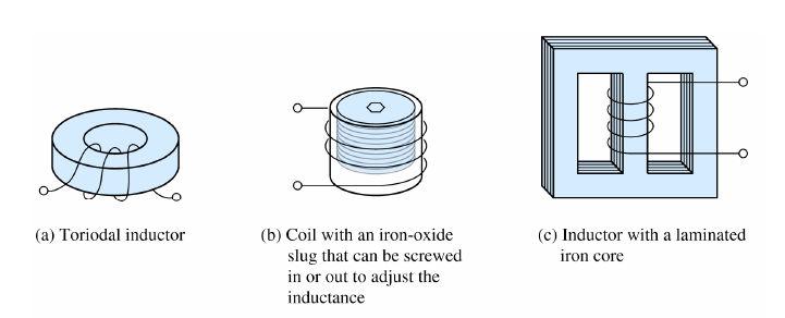
50 Applying the Summing Point Constraint
51 Inverting Ampliier v A o v v in
52 Summing Ampliier
53 Non-inverting Ampliiers v A o + v v in
54 A v Voltage Follower v v o in + + 0
55 Capacitance C q v v q t ( t ) i ( t ) dt + q ( t ) t 0 q C 0 v t C ( t ) i ( t ) dt + v ( t ) t 0 0
56 Capacitances in Parallel
57 Capacitances in Series + + C eq C C C 3
58 Inductance

59 Inductance The polarity o the voltage is such as to oppose the change in current (Lenz s law).
60 Series Inductances L L + L + L eq 3
61 Parallel Inductances L eq L + L + L 3
62 Mutual Inductance Fields are aiding Fields are opposing Magnetic lux produced by one coil links the other coil
63 Discharge o a Capacitance through a esistance i C i dt ( t ) ( ) dv C C C v t + 0 KCL at the top node o the circuit: q dq C q Cv i C v dt dt ( t ) dv C C C i v C ( t ) C dv dt + v ( t ) 0
64 Discharge o a Capacitance through a esistance ( t ) dv C C C dt + v ( t ) 0 dv ( t ) C dt C v C ( t ) We need a unction v C (t) that has the same orm as it s derivative. ( ) st v t Ke C Substituting this in or v c (t) CKse st + Ke st 0
65 Discharge o a Capacitance through a esistance Solving or s: s C Substituting into v c (t): v ( ) t C t Ke C Initial Condition: Full Solution: ( ) i v 0 + V C v ( ) t C t V e C i
66 Discharge o a Capacitance through a esistance v ( ) t C t C Ke To ind the unknown constant K, we need to use the boundary conditions at t0. At t0 the capacitor is initially charged to a voltage V i and then discharges through the resistor. ( ) i v 0 + V C v ( ) t C t V e C i
67 Discharge o a Capacitance through a esistance
68 Charging a Capacitance rom a DC Source through a esistance
69 Charging a Capacitance rom a DC Source through a esistance KCL at the node that joins the resistor and the capacitor C dv C dt ( t ) + v C ( t ) V S 0 Current into the capacitor: dv C c dt Current through the resistor: v C ( t ) V S
70 Charging a Capacitance rom a DC Source through a esistance C dv C dt ( t ) v + C ( t ) V S 0 earranging: dv C ( t ) C + v C ( t ) dt V S This is a linear irst-order dierential equation with contant coeicients.
71 Charging a Capacitance rom a DC Source through a esistance The boundary conditions are given by the act that the voltage across the capacitance cannot change instantaneously: v C ( 0 + ) v (0 ) C 0
72 Charging a Capacitance rom a DC Source through a esistance Try the solution: st v C ( t ) K + K e Substituting into the dierential equation: Gives: dv C ( t ) C + v C ( t ) V dt ( st + ) K e + K Cs S V S
73 Charging a Capacitance rom a DC Source through a esistance ( st + Cs ) K e + K V S For equality, the coeicient o e st must be zero: + Cs 0 s C Which gives K V S
74 Charging a Capacitance rom a DC Source through a esistance Substituting in or K and s: v st C ( t ) K + K e V S + K e t / C Evaluating at t0 and remembering that v C (0+)0 0 C (0 + ) V S + K e V S + K 0 K V v s Substituting in or K gives: v st C ( t ) K + K e V S V S e t / C
75 Charging a Capacitance rom a DC Source through a esistance v ( ) t τ t V V e C s s
76 DC Steady State i C ( t ) C dv C dt ( t ) In steady state, the voltage is constant, so the current through the capacitor is zero, so it behaves as an open circuit.
77 DC Steady State di ( t ) v ( t ) L L L dt In steady state, the current is constant, so the voltage across and inductor is zero, so it behaves as a short circuit.
78 DC Steady State The steps in determining the orced response or LC circuits with dc sources are:. eplace capacitances with open circuits.. eplace inductances with short circuits. 3. Solve the remaining circuit.
79 L Transient Analysis V S + i ( t ) + v ( t ) 0 di ( t i ( t ) + L dt ) V S
80 L Transient Analysis di ( t ) i ( t ) + L dt V S Try i ( t ) K + K e di ( t ) i ( t ) + L dt V S Try i ( t ) K + K st K + ( K + slk ) e V S V S K V K 00 V 50 Ω S A K + slk 0 st e s st L
 dt di ( t ) dt dx ( t ) dt + + + i i x ( ( ( t t t ) ) ) v v t t ( t ( ( t t ) ) ) Forcing")
81 C and L Circuits with General Sources First order dierential equation with constant coeicients L τ L di ( t ) dt di ( t ) dt dx ( t ) dt i i x ( ( ( t t t ) ) ) v v t t ( t ( ( t t ) ) ) Forcing unction
82 C and L Circuits with General Sources The general solution consists o two parts.
83 The particular solution (also called the orced response) is any expression that satisies the equation. dx ( τ dt t ) + x ( t ) ( t ) In order to have a solution that satisies the initial conditions, we must add the complementary solution to the particular solution.
84 The homogeneous equation is obtained by setting the orcing unction to zero. τ dx ( t dt + x ( t The complementary solution (also called the natural response) is obtained by solving the homogeneous equation. ) ) 0
85 Integrators and Dierentiators Integrators produce output voltages that are proportional to the running time integral o the input voltages. In a running time integral, the upper limit o integration is t.
86 v ( t ) v ( t )dt o in C t 0
87 Dierentiator Circuit ( ) dv v t C in o dt
88 Second Order Circuits ( t ) t di L + i 0 s dt ( t ) + i ( t ) dt + v ( ) v ( t ) C C 0 Dierentiating with respect to time: L d i dt ( t ) + di ( dt t ) + C i ( t ) dv s ( t ) dt
89 Deine: Second Order Circuits d i ( t ) di ( t ) dv s ( t ) + + i ( t ) dt L dt LC L dt α ω 0 L LC Dampening coeicient Undamped resonant requency ( t ) L dv s ( t ) dt Forcing unction d i dt ( t ) di ( t ) + α + ω 0 dt i ( t ) ( t )
90 Solution o the Second-Order Equation Particular d d i dt i dt ( t ) di ( t ) ( t ) di ( t ) + Complementary + α α solution dt dt + + ω 0 solution ω 0 i i ( t ) ( t ) ( t ) 0
91 Solution o the Complementary Equation d i dt ( t ) di ( t ) + α + ω i t dt 0 ( ) 0 Try s ( s s + i Ke + C st ( t α s α s ) + Factoring α ske + : + ω ω Ke 0 0 Characteristic st ) : st Ke 0 + st ω 0 0 equation Ke : st 0
92 Solution o the Complementary Equation oots o the characteristic equation: s α + α ω 0 s α α ω 0 ζ α ω 0 Dampening ratio
93 . Overdamped case (ζ > ). I ζ > (or equivalently, i α > ω 0 ), the roots o the characteristic equation are real and distinct. Then the complementary solution is: ( ) s t s t t K e K i c + e In this case, we say that the circuit is overdamped.
94 . Critically damped case (ζ ). I ζ (or equivalently, i α ω 0 ), the roots are real and equal. Then the complementary solution is ( ) s t s t t K e K i c + te In this case, we say that the circuit is critically damped.
95 3. Underdamped case (ζ < ). Finally, i ζ < (or equivalently, i α < ω 0 ), the roots are complex. (By the term complex, we mean that the roots involve the square root o.) In other words, the roots are o the orm: s α + j ω and s α j ω n n in which j is the square root o - and the natural requency is given by: ω ω α n 0
96 For complex roots, the complementary solution is o the orm: ( ) α t ( ) α t t K e ω t + K e sin ( t ) i c cos n ω n In this case, we say that the circuit is underdamped.
97 Circuits with Parallel L and C i V i L L t dq dt + L (0) c 0 vdt i i We can replace the circuit with it s Norton equivalent and then analyze the circuit by writing KCL at the top node: C dv ( dt t ) + v ( t ) + L t v ( t ) dt + i (0) 0 L i n ( t ) C dv dt
98 Circuits with Parallel L and C dt t di C t v LC dt t dv C dt t v d dt t di t v L dt t dv dt t v d C dierentiating t i i dt t v L t v dt t dv C n n t n L ) ( ) ( ) ( ) ( ) ( ) ( ) ( ) ( : ) ( (0) ) ( ) ( ) (
99 Circuits with Parallel L and C ) ( ) ( ) ( ) ( ) ( ) ( ) ( ) ( ) ( ) ( 0 0 t t v dt t dv dt t v d dt t di C t unction Forcing LC requency resonant Undamped C coeicient Dampening dt t di C t v LC dt t dv C dt t v d n n ω α ω α
100 Circuits with Parallel L and C d v dt ( t ) dv ( t ) + α + ω 0 dt v ( t ) ( t ) This is the same equation as we ound or the series LC circuit with the ollowing changes or α: Parallel circuit α Series circuit α C L
101 Complex Impedances-Inductor V j ω I L L L Z j ω L ω L L 90 o V Z I L L L
102 Complex Impedances-Inductor
103 Complex Impedances-Capacitor V Z I C C C o Z j C ω C j ω C ω C 90 I V
104 Complex Impedances-Capacitor
105 Impedances-esistor I V
106 Impedances-esistor
107 Kirchho s Laws in Phasor Form We can apply KVL directly to phasors. The sum o the phasor voltages equals zero or any closed path. V + V V 3 0 The sum o the phasor currents entering a node must equal the sum o the phasor currents leaving. in I out I
108 Power in AC Circuits o V V m 0 I I m θ Z Z θ where I m V m Z For θ>0 the load is called inductive since ZjωL or an inductor For θ<0 the load is capacitive since Z-j/ωC or a capacitor
109 Load Impedance in the Complex Plane Z Z cos( θ ) sin( θ ) θ Z X Z + jx
110 Power or a General Load I the phase angle or the voltage is not zero, we deine the power angle θ: Power angle: θ θ voltage θ current P V I rms rms cos( θ ) PF cos( θ )
111 AC Power Calculations Average Power: P V I cos θ rms rms ( ) [ W ] eactive Power: Q V I sin θ rms rms ( ) [ VA ] [ ] Apparent Power: V I VA MS MS
112 Power Triangles Average power P + Q ( V I ) rms rms Average power eactive power Apparent power
113 Thevenin Equivalent Circuits The Thevenin equivalent or an ac circuit consists o a phasor voltage source V t in series with a complex impedance Z t
114 Thevenin Equivalent Circuits The Thévenin voltage is equal to the open-circuit phasor voltage o the original circuit. V t V oc We can ind the Thévenin impedance by zeroing the independent sources and determining the impedance looking into the circuit terminals.
115 Thevenin Equivalent Circuits The Thévenin impedance equals the open-circuit voltage divided by the short-circuit current. V V oc t Z t I sc I sc
116 Norton Equivalent Circuit The Norton equivalent or an ac circuit consists o a phasor current source I n in parallel with a complex impedance Z t I I n sc
117 Maximum Average Power Transer The Thevenin equivalent o a two-terminal circuit delivering power to a load impedance.
118 Maximum Average Power Transer I the load can take on any complex value, maximum power transer is attained or a load impedance equal to the complex conjugate o the Thévenin impedance. I the load is required to be a pure resistance, maximum power transer is attained or a load resistance equal to the magnitude o the Thévenin impedance.
119 Transer Functions The transer unction H( ) o the two-port ilter is deined to be the ratio o the phasor output voltage to the phasor input voltage as a unction o requency: H ( ) V V out in
120 First-Order Low Pass Filter C j C j H C j C j C j C j B B in out in out in π π π π π π ) / ( ) ( V V V I V V I Hal power requency
121 ( ) ( ) ( ) + + B B B j H arctan 0 o ( ) ( ) B H + ( ) B H arctan First-Order Low Pass Filter
122 First-Order Low Pass Filter For low requency signals the magnitude o the transer unction is unity and the phase is 0. Low requency signals are passed while high requency signals are attenuated and phase shited.
123 Magnitude Bode Plot or First-Order Low Pass Filter
124 . A horizontal line at zero or < B /0.. A sloping line rom zero phase at B /0 to 90 at 0 B. 3. A horizontal line at 90 or > 0 B.
125 First-Order High-Pass Filter C where j j C j C j C j C j B B B in out in in in out π π π π π ) / ( ) / ( + + V V V V V V
126 First-Order High-Pass Filter H H H ( ) ( ) ( ) V V out in j + ( B ) ( ) + arctan ( B ) j ( ) B 90 o ( ) B B + 90 o o ( B ) 90 ( ) arctan ( ) arctan B ( ) B B
127 H First-Order High-Pass Filter ( ) ( ) B ( ) o H 90 arctan ( ) B + ( ) B
128 Bode Plots or the First-Order High- Pass Filter For For << B H >> H B ( ) 0 log( B ) ( ) 0 log( ) 0log ( ) 0 B B H For For H For For ( ) ( ) 0 log( B ) 0log + ( B ) << B H ( ) 0 log( B ) >> H ( ) 0 log( ) 0log ( ) ( ) << >> 90 H H ( ) o ( ) 0 90 o B o B B arctan B B B 0
129 Series esonance LC LC C L resonance For C j L j Z s π π π π π π ) ( : ) ( For resonance the reactance o the inductor and the capacitor cancel:
130 Q s Substitute L Q s Series esonance Quality actor Q S eactance o inductance at π π 0 ( π ) 0 esistance L ( C 0 ) rom C 0 resonance π LC
131 Series esonant Band-Pass Filter jq jq jq Z s s s s s s s s / ) ( V V V I V V V I
132 Series esonant Band-Pass Filter V V s + jq s ( ) 0 0
133 Parallel esonance Z p π ( ) + j π C j ( L ) At resonance Z P is purely resistive: j ( π L ) π C j π LC
134 Q P Substitute L Q P Parallel esonance Quality actor Q P π π esistance eactance o inductance at 0 ( π ) 0 L ( C 0 ) rom C 0 resonance π LC
135 V out I Z P Parallel esonance + jq P I 0 0 V out or constant current, varying the requency
136 Second Order Low-Pass Filter jq jq LC L j C j H LC L j C j C j L j C j Z Z Z Z S S in out in in in C L C out ) / ( ) ( π π π π π π π π π V V V V V V
137 ( ) ( ) ( ) ( ) ( ) ( ) ( ) ( ) ( ) Q Q H Q Tan Q Q jq jq H S s s S s s s o in out V V Second Order Low-Pass Filter
138 Second Order Low-Pass Filter
139 Second Order High-Pass Filter At low requency the capacitor is an open circuit At high requency the capacitor is a short and the inductor is open
140 Second Order Band-Pass Filter At low requency the capacitor is an open circuit At high requency the inductor is an open circuit
141 Second Order Band-eject Filter At low requency the capacitor is an open circuit At high requency the inductor is an open circuit
 / ( ) ( ) ( + + + + + A low-pass ilter with a dc gain o - /")
142 First-Order Low-Pass Filter B B i i i i i o C j C j Z Z H C j Z C j C j Z Z Z V V H π π π π π ) / ( ) ( ) ( A low-pass ilter with a dc gain o - / i
 / ( ) / ( ) ( ) ( + + + + + A high-pass ilter with a high requency gain o - /")
143 First-Order High-Pass Filter i i B B B i i i i i i i i i i i i i i i i i o C j j C j C j C j C j C j Z Z H Z C j Z Z Z v v H π π π π π π π ) / ( ) / ( ) ( ) ( A high-pass ilter with a high requency gain o - / i
144 Flux Linkages and Faraday s Law Magnetic lux passing through a surace area A: φ B d A A For a constant magnetic lux density perpendicular to the surace: BA The lux linking a coil with N turns: λ N φ
145 Faraday s Law Faraday s law o magnetic induction: e d λ dt The voltage induced in a coil whenever its lux linkages are changing. Changes occur rom: Magnetic ield changing in time Coil moving relative to magnetic ield
146 Lenz s Law Lenz s law states that the polarity o the induced voltage is such that the voltage would produce a current (through an external resistance) that opposes the original change in lux linkages.
147 Lenz s Law
148 Magnetic Field Intensity and Ampère s Law H B µ µ 0 4 π 0 H Magnetic 7 Wb Am ield intensity µ r µ µ 0 elative Ampère s Law: H permeability dl i

149 Ampère s Law The line integral o the magnetic ield intensity around a closed path is equal to the sum o the currents lowing through the surace bounded by the path.
150 Magnetic Field Intensity and Ampère s Law H d l Hdl cos(θ ) dot product I the magnetic ield H has a constant magnitude and points in the same direction as the incremental length d l Hl Σ i
151 Magnetic Circuits In many engineering applications, we need to compute the magnetic ields or structures that lack suicient symmetry or straight-orward application o Ampère s law. Then, we use an approximate method known as magnetic-circuit analysis.
 reluctance o a path or magnetic lux l µa Analog: esistance F φ Analog: Ohm s")
152 magnetomotive orce (mm) o an N-turn current-carrying coil F N I Analog: Voltage (em) reluctance o a path or magnetic lux l µa Analog: esistance F φ Analog: Ohm s Law
153 I Nr NI r r A l r A l µ φ µ π π µ µ π π F F Magnetic Circuit or Toroidal Coil

154 A Magnetic Circuit with eluctances in Series and Parallel
155 a a a a a a c b a a b c b a b a total c b a c total A B A B divider current Ni φ φ φ φ φ φ φ ) ( A Magnetic Circuit with eluctances in Series and Parallel
156 i i L λ λ i i L λ λ i i i i M λ λ λ λ Sel inductance or coil Sel inductance or coil Mutual inductance between coils and : Mutual Inductance
157 Mutual Inductance Total luxes linking the coils: λ λ ± λ λ λ ± λ

158 Mutual Inductance Currents entering the dotted terminals produce aiding luxes
159 Circuit Equations or Mutual Inductance λ λ e e L i ± d d Mi dt λ λ dt ± Mi + L L i di ± M dt di ± M dt + L di dt di dt
160 Ideal Transormers
161 Ideal Transormers ( ) t N v ( t ) N v N i t ) i ( t N ( ) p ( t ) p ( t )
162 Mechanical Analog ( ) ( ) ) ( ) ( F l l F t i N N t i d l l d t v N N t v d d
163 Impedance Transormations Z V N Z L I N L
164 Semiconductor Diode
165 Shockley Equation v D I s exp nv T kt i V mv D T 6 q i v exp D or >> nv T D I s v D V T i D I s or v D << - V T until reaching reverse breakdown
166 Load-Line Analysis o Diode Circuits V i + v SS D D Assume V SS and are known. Find i D and v D
167 Load-Line Analysis o Diode Circuits V i + V + SS D v D SS i D v D
168 Ideal Diode Model The ideal diode acts as a short circuit or orward currents and as an open circuit with reverse voltage applied. i D > 0 v D < 0 diode is in the on state v D < 0 I D 0 diode is in the o state
169 Assumed States or Analysis o Ideal-Diode Circuits. Assume a state or each diode, either on (i.e., a short circuit) or o (i.e., an open circuit). For n diodes there are n possible combinations o diode states.. Analyze the circuit to determine the current through the diodes assumed to be on and the voltage across the diodes assumed to be o.
170 3. Check to see i the result is consistent with the assumed state or each diode. Current must low in the orward direction or diodes assumed to be on. Furthermore, the voltage across the diodes assumed to be o must be positive at the cathode (i.e., reverse bias). 4. I the results are consistent with the assumed states, the analysis is inished. Otherwise, return to step and choose a dierent combination o diode states.
171 Hal-Wave ectiier with esistive Load The diode is on during the positive hal o the cycle. The diode is o during the negative hal o the cycle.
172 Hal-Wave ectiier with Smoothing Capacitor The charge removed rom the capacitor in one cycle: Q I L T VC V r C
173 Full-Wave ectiier The capacitance required or a ull-wave rectiier is given by: I C L V T r
174 Full-Wave ectiier
175 Clipper Circuit

176 NPN Bipolar Junction Transistor
177 Bias Conditions or PN Junctions The base emitter p-n junction o an npn transistor is normally orward biased The base collector p-n junction o an npn transistor is normally reverse biased
178 Equations o Operation i E v BE I ES exp V T From Kircho s current law: i + i i E C B
179 Equations o Operation Deine α as the ratio o collector current to emitter current: α Values or α range rom 0.9 to with 0.99 being typical. Since: i i C E i 0 E i C + i B 0.99 i E + i B i B 0. i Most o the emitter current comes rom the collector and very little ( %) rom the base. E
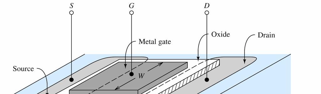
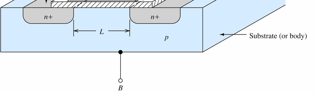
180 Equations o Operation Deine β as the ratio o collector current to base current: β i i C B α α Values or β range rom about 0 to,000 with a common value being β 00. i C β i B The collector current is an ampliied version o the base current.

181 The base region is very thin Only a small raction o the emitter current lows into the base provided that the collector-base junction is reverse biased and the base-emitter junction is orward biased.
182 Common-Emitter Characteristics v BC v CE v BC i v CE v > BE v BE v CE v BC < 0 reverse bias
183 Common-Emitter Input Characteristics v BE i B ( α ) I ES exp V T
184 Common-Emitter Output Characteristics i C β i B or β 00
185 Ampliication by the BJT A small change in v BE results in a large change in i B i the base emitter is orward biased. Provided v CE is more than a ew tenth s o a volt, this change in i B results in a larger change in i C since i C βi B.
186 Common-Emitter Ampliier
187 Load-Line Analysis o a Common Emitter Ampliier (Input Circuit) ( t ) i ( t ) v ( t ) V + v + BB in B B BE
188 Load-Line Analysis o a Common Emitter Ampliier (Output Circuit) V + i v CC C C CE
189 Inverting Ampliier As v in (t) goes positive, the load line moves upward and to the right, and the value o i B increases. This causes the operating point on the output to move upwards, decreasing v CE An increase in v in (t) results in a much larger decrease in v CE so that the common emitter ampliier is an inverting ampliier
190 PNP Bipolar Junction Transistor Except or reversal o current directions and voltage polarities, the pnp BJT is almost identical to the npn BJT.
191 PNP Bipolar Junction Transistor i i i i C B C E α i ( β i i C E B + α ) i i B E
192 NMOS Transistor
193 NMOS Transistor
194 Operation in the Cuto egion i 0 or v V D GS to

195 Operation Slightly Above Cut-O By applying a positive bias between the Gate (G) and the body (B), electrons are attracted to the gate to orm a conducting n-type channel between the source and drain. The positive charge on the gate and the negative charge in the channel orm a capacitor where:
196 Operation Slightly Above Cut-O W i µε ) DS ( v GS V to v Lt ox DS For small values o v DS, i D is proportional to v DS. The device behaves as a resistance whose value depends on v GS.
197 Operation in the Triode egion [ ( ) ] v v v i D C GS to DS v DS W C L KP
198
199 Load-Line Analysis o a Simple NMOS Circuit v ( t ) v ( t ) + 4 GS in V
200 Load-Line Analysis o a Simple NMOS Circuit ( t ) v ( t ) v i + DD D D DS
201 Load-Line Analysis o a Simple NMOS Circuit
202 CMOS Inverter
203 Two-Input CMOS NAND Gate
204 Two-Input CMOS NO Gate
ECE 205: Intro Elec & Electr Circuits
 ECE 205: Intro Elec & Electr Circuits Final Exam Study Guide Version 1.00 Created by Charles Feng http://www.fenguin.net ECE 205: Intro Elec & Electr Circuits Final Exam Study Guide 1 Contents 1 Introductory
Part 4: Electromagnetism. 4.1: Induction. A. Faraday's Law. The magnetic flux through a loop of wire is
 1 Part 4: Electromagnetism 4.1: Induction A. Faraday's Law The magnetic flux through a loop of wire is Φ = BA cos θ B A B = magnetic field penetrating loop [T] A = area of loop [m 2 ] = angle between field
Sinusoidal Steady State Analysis (AC Analysis) Part II
 Part II") Sinusoidal Steady State Analysis (AC Analysis) Part II Amin Electronics and Electrical Communications Engineering Department (EECE) Cairo University elc.n102.eng@gmail.com http://scholar.cu.edu.eg/refky/
Sinusoidal Steady State Analysis (AC Analysis) Part II Amin Electronics and Electrical Communications Engineering Department (EECE) Cairo University elc.n102.eng@gmail.com http://scholar.cu.edu.eg/refky/
ECE2262 Electric Circuits. Chapter 6: Capacitance and Inductance
 ECE2262 Electric Circuits Chapter 6: Capacitance and Inductance Capacitors Inductors Capacitor and Inductor Combinations Op-Amp Integrator and Op-Amp Differentiator 1 CAPACITANCE AND INDUCTANCE Introduces
Bipolar Junction Transistor (BJT) - Introduction
 - Introduction") Bipolar Junction Transistor (BJT) - Introduction It was found in 1948 at the Bell Telephone Laboratories. It is a three terminal device and has three semiconductor regions. It can be used in signal amplification
Bipolar Junction Transistor (BJT) - Introduction It was found in 1948 at the Bell Telephone Laboratories. It is a three terminal device and has three semiconductor regions. It can be used in signal amplification
Chapter 31 Electromagnetic Oscillations and Alternating Current LC Oscillations, Qualitatively
 Chapter 3 Electromagnetic Oscillations and Alternating Current LC Oscillations, Qualitatively In the LC circuit the charge, current, and potential difference vary sinusoidally (with period T and angular
Sinusoidal Steady State Analysis (AC Analysis) Part I
 Part I") Sinusoidal Steady State Analysis (AC Analysis) Part I Amin Electronics and Electrical Communications Engineering Department (EECE) Cairo University elc.n102.eng@gmail.com http://scholar.cu.edu.eg/refky/
Sinusoidal Steady State Analysis (AC Analysis) Part I Amin Electronics and Electrical Communications Engineering Department (EECE) Cairo University elc.n102.eng@gmail.com http://scholar.cu.edu.eg/refky/
Basics of Network Theory (Part-I)
") Basics of Network Theory (PartI). A square waveform as shown in figure is applied across mh ideal inductor. The current through the inductor is a. wave of peak amplitude. V 0 0.5 t (m sec) [Gate 987: Marks]
Basics of Network Theory (PartI). A square waveform as shown in figure is applied across mh ideal inductor. The current through the inductor is a. wave of peak amplitude. V 0 0.5 t (m sec) [Gate 987: Marks]
Electrical Eng. fundamental Lecture 1
 Electrical Eng. fundamental Lecture 1 Contact details: h-elhelw@staffs.ac.uk Introduction Electrical systems pervade our lives; they are found in home, school, workplaces, factories,
Chapter 13 Small-Signal Modeling and Linear Amplification
 Chapter 13 Small-Signal Modeling and Linear Amplification Microelectronic Circuit Design Richard C. Jaeger Travis N. Blalock 1/4/12 Chap 13-1 Chapter Goals Understanding of concepts related to: Transistors
Homework Assignment 08
 Homework Assignment 08 Question 1 (Short Takes) Two points each unless otherwise indicated. 1. Give one phrase/sentence that describes the primary advantage of an active load. Answer: Large effective resistance
CS 436 HCI Technology Basic Electricity/Electronics Review
 CS 436 HCI Technology Basic Electricity/Electronics Review *Copyright 1997-2008, Perry R. Cook, Princeton University August 27, 2008 1 Basic Quantities and Units 1.1 Charge Number of electrons or units
(amperes) = (coulombs) (3.1) (seconds) Time varying current. (volts) =
 = (coulombs) (3.1) (seconds) Time varying current. (volts) =") 3 Electrical Circuits 3. Basic Concepts Electric charge coulomb of negative change contains 624 0 8 electrons. Current ampere is a steady flow of coulomb of change pass a given point in a conductor in
3 Electrical Circuits 3. Basic Concepts Electric charge coulomb of negative change contains 624 0 8 electrons. Current ampere is a steady flow of coulomb of change pass a given point in a conductor in
ECE2262 Electric Circuits. Chapter 6: Capacitance and Inductance
 ECE2262 Electric Circuits Chapter 6: Capacitance and Inductance Capacitors Inductors Capacitor and Inductor Combinations 1 CAPACITANCE AND INDUCTANCE Introduces two passive, energy storing devices: Capacitors
Chapter 15 Magnetic Circuits and Transformers
 Chapter 15 Magnetic Circuits and Transformers Chapter 15 Magnetic Circuits and Transformers 1. Understand magnetic fields and their interactio with moving charges. 2. Use the right-hand rule to determine
EE 330 Lecture 22. Small Signal Modelling Operating Points for Amplifier Applications Amplification with Transistor Circuits
 EE 330 Lecture 22 Small Signal Modelling Operating Points for Amplifier Applications Amplification with Transistor Circuits Exam 2 Friday March 9 Exam 3 Friday April 13 Review Session for Exam 2: 6:00
SECOND ENGINEER REG III/2 MARINE ELECTRO-TECHNOLOGY. 1. Understands the physical construction and characteristics of basic components.
 SECOND ENGINEER REG III/ MARINE ELECTRO-TECHNOLOGY LIST OF TOPICS A B C D Electric and Electronic Components Electric Circuit Principles Electromagnetism Electrical Machines The expected learning outcome
Chapter 2. Engr228 Circuit Analysis. Dr Curtis Nelson
 Chapter 2 Engr228 Circuit Analysis Dr Curtis Nelson Chapter 2 Objectives Understand symbols and behavior of the following circuit elements: Independent voltage and current sources; Dependent voltage and
Analog Computing Technique
 Analog Computing Technique by obert Paz Chapter Programming Principles and Techniques. Analog Computers and Simulation An analog computer can be used to solve various types o problems. It solves them in
Chapter 10 AC Analysis Using Phasors
 Chapter 10 AC Analysis Using Phasors 10.1 Introduction We would like to use our linear circuit theorems (Nodal analysis, Mesh analysis, Thevenin and Norton equivalent circuits, Superposition, etc.) to
Electronic Circuits Summary
 Electronic Circuits Summary Andreas Biri, D-ITET 6.06.4 Constants (@300K) ε 0 = 8.854 0 F m m 0 = 9. 0 3 kg k =.38 0 3 J K = 8.67 0 5 ev/k kt q = 0.059 V, q kt = 38.6, kt = 5.9 mev V Small Signal Equivalent
Introduction to AC Circuits (Capacitors and Inductors)
") Introduction to AC Circuits (Capacitors and Inductors) Amin Electronics and Electrical Communications Engineering Department (EECE) Cairo University elc.n102.eng@gmail.com http://scholar.cu.edu.eg/refky/
Introduction to AC Circuits (Capacitors and Inductors) Amin Electronics and Electrical Communications Engineering Department (EECE) Cairo University elc.n102.eng@gmail.com http://scholar.cu.edu.eg/refky/
Basic Electronics. Introductory Lecture Course for. Technology and Instrumentation in Particle Physics Chicago, Illinois June 9-14, 2011
 Basic Electronics Introductory Lecture Course for Technology and Instrumentation in Particle Physics 2011 Chicago, Illinois June 9-14, 2011 Presented By Gary Drake Argonne National Laboratory drake@anl.gov
SOME USEFUL NETWORK THEOREMS
 APPENDIX D SOME USEFUL NETWORK THEOREMS Introduction In this appendix we review three network theorems that are useful in simplifying the analysis of electronic circuits: Thévenin s theorem Norton s theorem
DC Biasing. Dr. U. Sezen & Dr. D. Gökçen (Hacettepe Uni.) ELE230 Electronics I 15-Mar / 59
 ELE230 Electronics I 15-Mar / 59") Contents Three States of Operation BJT DC Analysis Fixed-Bias Circuit Emitter-Stabilized Bias Circuit Voltage Divider Bias Circuit DC Bias with Voltage Feedback Various Dierent Bias Circuits pnp Transistors
Contents Three States of Operation BJT DC Analysis Fixed-Bias Circuit Emitter-Stabilized Bias Circuit Voltage Divider Bias Circuit DC Bias with Voltage Feedback Various Dierent Bias Circuits pnp Transistors
Handout 10: Inductance. Self-Inductance and inductors
 1 Handout 10: Inductance Self-Inductance and inductors In Fig. 1, electric current is present in an isolate circuit, setting up magnetic field that causes a magnetic flux through the circuit itself. This
EE292: Fundamentals of ECE
 EE292: Fundamentals of ECE Fall 2012 TTh 10:00-11:15 SEB 1242 Lecture 20 121101 http://www.ee.unlv.edu/~b1morris/ee292/ 2 Outline Chapters 1-3 Circuit Analysis Techniques Chapter 10 Diodes Ideal Model
EIT Review 1. FE/EIT Review. Circuits. John A. Camara, Electrical Engineering Reference Manual, 6 th edition, Professional Publications, Inc, 2002.
 FE/EIT eview Circuits Instructor: uss Tatro eferences John A. Camara, Electrical Engineering eference Manual, 6 th edition, Professional Publications, Inc, 00. John A. Camara, Practice Problems for the
E40M Review - Part 1
 E40M Review Part 1 Topics in Part 1 (Today): KCL, KVL, Power Devices: V and I sources, R Nodal Analysis. Superposition Devices: Diodes, C, L Time Domain Diode, C, L Circuits Topics in Part 2 (Wed): MOSFETs,
2. The following diagram illustrates that voltage represents what physical dimension?
 BioE 1310 - Exam 1 2/20/2018 Answer Sheet - Correct answer is A for all questions 1. A particular voltage divider with 10 V across it consists of two resistors in series. One resistor is 7 KΩ and the other
ELECTROMAGNETIC INDUCTION AND FARADAY S LAW
 ELECTROMAGNETIC INDUCTION AND FARADAY S LAW Magnetic Flux The emf is actually induced by a change in the quantity called the magnetic flux rather than simply py by a change in the magnetic field Magnetic
ENGG 225. David Ng. Winter January 9, Circuits, Currents, and Voltages... 5
 ENGG 225 David Ng Winter 2017 Contents 1 January 9, 2017 5 1.1 Circuits, Currents, and Voltages.................... 5 2 January 11, 2017 6 2.1 Ideal Basic Circuit Elements....................... 6 3 January
Lecture 11 - AC Power
 - AC Power 11/17/2015 Reading: Chapter 11 1 Outline Instantaneous power Complex power Average (real) power Reactive power Apparent power Maximum power transfer Power factor correction 2 Power in AC Circuits
EIT Review. Electrical Circuits DC Circuits. Lecturer: Russ Tatro. Presented by Tau Beta Pi The Engineering Honor Society 10/3/2006 1
 EIT Review Electrical Circuits DC Circuits Lecturer: Russ Tatro Presented by Tau Beta Pi The Engineering Honor Society 10/3/2006 1 Session Outline Basic Concepts Basic Laws Methods of Analysis Circuit
Physics 142 AC Circuits Page 1. AC Circuits. I ve had a perfectly lovely evening but this wasn t it. Groucho Marx
 Physics 142 A ircuits Page 1 A ircuits I ve had a perfectly lovely evening but this wasn t it. Groucho Marx Alternating current: generators and values It is relatively easy to devise a source (a generator
EE-0001 PEEE Refresher Course. Week 1: Engineering Fundamentals
 EE-000 PEEE efresher Course Week : Engineering Fundamentals Engineering Fundamentals Bentley Chapters & Camara Chapters,, & 3 Electrical Quantities Energy (work), power, charge, current Electrostatic pressure,
Gen. Phys. II Exam 2 - Chs. 21,22,23 - Circuits, Magnetism, EM Induction Mar. 5, 2018
 Gen. Phys. II Exam 2 - Chs. 21,22,23 - Circuits, Magnetism, EM Induction Mar. 5, 2018 Rec. Time Name For full credit, make your work clear. Show formulas used, essential steps, and results with correct
Mod. Sim. Dyn. Sys. Amplifiers page 1
 AMPLIFIERS A circuit containing only capacitors, amplifiers (transistors) and resistors may resonate. A circuit containing only capacitors and resistors may not. Why does amplification permit resonance
Sinusoidal Steady-State Analysis
 Chapter 4 Sinusoidal Steady-State Analysis In this unit, we consider circuits in which the sources are sinusoidal in nature. The review section of this unit covers most of section 9.1 9.9 of the text.
4/27 Friday. I have all the old homework if you need to collect them.
 4/27 Friday Last HW: do not need to turn it. Solution will be posted on the web. I have all the old homework if you need to collect them. Final exam: 7-9pm, Monday, 4/30 at Lambert Fieldhouse F101 Calculator
CARLETON UNIVERSITY. FINAL EXAMINATION December DURATION 3 HOURS No. of Students 130
 ALETON UNIVESITY FINAL EXAMINATION December 005 DUATION 3 HOUS No. of Students 130 Department Name & ourse Number: Electronics ELE 3509 ourse Instructor(s): Prof. John W. M. ogers and alvin Plett AUTHOIZED
b) (4) How large is the current through the 2.00 Ω resistor, and in which direction?
 (4) How large is the current through the 2.00 Ω resistor, and in which direction?") General Physics II Exam 2 - Chs. 19 21 - Circuits, Magnetism, EM Induction - Sep. 29, 2016 Name Rec. Instr. Rec. Time For full credit, make your work clear. Show formulas used, essential steps, and results
General Physics II Exam 2 - Chs. 19 21 - Circuits, Magnetism, EM Induction - Sep. 29, 2016 Name Rec. Instr. Rec. Time For full credit, make your work clear. Show formulas used, essential steps, and results
Chapter 32A AC Circuits. A PowerPoint Presentation by Paul E. Tippens, Professor of Physics Southern Polytechnic State University
 Chapter 32A AC Circuits A PowerPoint Presentation by Paul E. Tippens, Professor of Physics Southern Polytechnic State University 2007 Objectives: After completing this module, you should be able to: Describe
Biasing the CE Amplifier
 Biasing the CE Amplifier Graphical approach: plot I C as a function of the DC base-emitter voltage (note: normally plot vs. base current, so we must return to Ebers-Moll): I C I S e V BE V th I S e V th
Review of Basic Electrical and Magnetic Circuit Concepts EE
 Review of Basic Electrical and Magnetic Circuit Concepts EE 442-642 Sinusoidal Linear Circuits: Instantaneous voltage, current and power, rms values Average (real) power, reactive power, apparent power,
Mod. Sim. Dyn. Sys. Amplifiers page 1
 AMPLIFIERS A circuit containing only capacitors, amplifiers (transistors) and resistors may resonate. A circuit containing only capacitors and resistors may not. Why does amplification permit resonance
11. AC Circuit Power Analysis
 . AC Circuit Power Analysis Often an integral part of circuit analysis is the determination of either power delivered or power absorbed (or both). In this chapter First, we begin by considering instantaneous
ELECTROMAGNETIC INDUCTION
 ELECTROMAGNETIC INDUCTION 1. Magnetic Flux 2. Faraday s Experiments 3. Faraday s Laws of Electromagnetic Induction 4. Lenz s Law and Law of Conservation of Energy 5. Expression for Induced emf based on
EE40 Midterm Review Prof. Nathan Cheung
 EE40 Midterm Review Prof. Nathan Cheung 10/29/2009 Slide 1 I feel I know the topics but I cannot solve the problems Now what? Slide 2 R L C Properties Slide 3 Ideal Voltage Source *Current depends d on
Mechatronics 1: ME 392Q-6 & 348C 31-Aug-07 M.D. Bryant. Analogous Systems. e(t) Se: e. ef = p/i. q = p /I, p = " q C " R p I + e(t)
 Se: e. ef = p/i. q = p /I, p = q C R p I + e(t)") V + - K R + - - k b V R V L L J + V C M B Analogous Systems i = q. + ω = θ. C -. λ/l = q v = x F T. Se: e e(t) e = p/i R: R 1 I: I e C = q/c C = dq/dt e I = dp/dt Identical dierential equations & bond
V + - K R + - - k b V R V L L J + V C M B Analogous Systems i = q. + ω = θ. C -. λ/l = q v = x F T. Se: e e(t) e = p/i R: R 1 I: I e C = q/c C = dq/dt e I = dp/dt Identical dierential equations & bond
Homework Assignment 09
 Homework Assignment 09 Question 1 (Short Takes) Two points each unless otherwise indicated. 1. What is the 3-dB bandwidth of the amplifier shown below if r π = 2.5K, r o = 100K, g m = 40 ms, and C L =
Get Discount Coupons for your Coaching institute and FREE Study Material at ELECTROMAGNETIC INDUCTION
 ELECTROMAGNETIC INDUCTION 1. Magnetic Flux 2. Faraday s Experiments 3. Faraday s Laws of Electromagnetic Induction 4. Lenz s Law and Law of Conservation of Energy 5. Expression for Induced emf based on
Notes on Electric Circuits (Dr. Ramakant Srivastava)
") Notes on Electric ircuits (Dr. Ramakant Srivastava) Passive Sign onvention (PS) Passive sign convention deals with the designation of the polarity of the voltage and the direction of the current arrow
Notes on Electric ircuits (Dr. Ramakant Srivastava) Passive Sign onvention (PS) Passive sign convention deals with the designation of the polarity of the voltage and the direction of the current arrow
Chapter 2 - DC Biasing - BJTs
 Objectives Chapter 2 - DC Biasing - BJTs To Understand: Concept of Operating point and stability Analyzing Various biasing circuits and their comparison with respect to stability BJT A Review Invented
ELECTRONICS E # 1 FUNDAMENTALS 2/2/2011
 FE Review 1 ELECTRONICS E # 1 FUNDAMENTALS Electric Charge 2 In an electric circuit it there is a conservation of charge. The net electric charge is constant. There are positive and negative charges. Like
Circuits with Capacitor and Inductor
 Circuits with Capacitor and Inductor We have discussed so far circuits only with resistors. While analyzing it, we came across with the set of algebraic equations. Hereafter we will analyze circuits with
Electronic Circuits 1. Transistor Devices. Contents BJT and FET Characteristics Operations. Prof. C.K. Tse: Transistor devices
 Electronic Circuits 1 Transistor Devices Contents BJT and FET Characteristics Operations 1 What is a transistor? Three-terminal device whose voltage-current relationship is controlled by a third voltage
Tutorial #4: Bias Point Analysis in Multisim
 SCHOOL OF ENGINEERING AND APPLIED SCIENCE DEPARTMENT OF ELECTRICAL AND COMPUTER ENGINEERING ECE 2115: ENGINEERING ELECTRONICS LABORATORY Tutorial #4: Bias Point Analysis in Multisim INTRODUCTION When BJTs
Schedule. ECEN 301 Discussion #20 Exam 2 Review 1. Lab Due date. Title Chapters HW Due date. Date Day Class No. 10 Nov Mon 20 Exam Review.
 Schedule Date Day lass No. 0 Nov Mon 0 Exam Review Nov Tue Title hapters HW Due date Nov Wed Boolean Algebra 3. 3.3 ab Due date AB 7 Exam EXAM 3 Nov Thu 4 Nov Fri Recitation 5 Nov Sat 6 Nov Sun 7 Nov Mon
Physics 2B: Review for Celebration #2. Chapter 22: Current and Resistance
 Physics 2: eview for Celebration #2 Chapter 22: Current and esistance Current: q Current: I [I] amps (A) 1 A 1 C/s t Current flows because a potential difference across a conductor creates an electric
12 Chapter Driven RLC Circuits
 hapter Driven ircuits. A Sources... -. A ircuits with a Source and One ircuit Element... -3.. Purely esistive oad... -3.. Purely Inductive oad... -6..3 Purely apacitive oad... -8.3 The Series ircuit...
Assessment Schedule 2015 Physics: Demonstrate understanding of electrical systems (91526)
") NCEA Level 3 Physics (91526) 2015 page 1 of 6 Assessment Schedule 2015 Physics: Demonstrate understanding of electrical systems (91526) Evidence Q Evidence Achievement Achievement with Merit Achievement
NCEA Level 3 Physics (91526) 2015 page 1 of 6 Assessment Schedule 2015 Physics: Demonstrate understanding of electrical systems (91526) Evidence Q Evidence Achievement Achievement with Merit Achievement
BASIC NETWORK ANALYSIS
 SECTION 1 BASIC NETWORK ANALYSIS A. Wayne Galli, Ph.D. Project Engineer Newport News Shipbuilding Series-Parallel dc Network Analysis......................... 1.1 Branch-Current Analysis of a dc Network......................
RLC Circuit (3) We can then write the differential equation for charge on the capacitor. The solution of this differential equation is
 We can then write the differential equation for charge on the capacitor. The solution of this differential equation is") RLC Circuit (3) We can then write the differential equation for charge on the capacitor The solution of this differential equation is (damped harmonic oscillation!), where 25 RLC Circuit (4) If we charge
RLC Circuit (3) We can then write the differential equation for charge on the capacitor The solution of this differential equation is (damped harmonic oscillation!), where 25 RLC Circuit (4) If we charge
E2.2 Analogue Electronics
 E2.2 Analogue Electronics Instructor : Christos Papavassiliou Office, email : EE 915, c.papavas@imperial.ac.uk Lectures : Monday 2pm, room 408 (weeks 2-11) Thursday 3pm, room 509 (weeks 4-11) Problem,
ECE2262 Electric Circuit
 ECE2262 Electric Circuit Chapter 7: FIRST AND SECOND-ORDER RL AND RC CIRCUITS Response to First-Order RL and RC Circuits Response to Second-Order RL and RC Circuits 1 2 7.1. Introduction 3 4 In dc steady
(a) zero. B 2 l 2. (c) (b)
 zero. B 2 l 2. (c) (b)") 1. Two identical co-axial circular loops carry equal currents circulating in the same direction: (a) The current in each coil decrease as the coils approach each other. (b) The current in each coil increase
1. Two identical co-axial circular loops carry equal currents circulating in the same direction: (a) The current in each coil decrease as the coils approach each other. (b) The current in each coil increase
Chapter 33. Alternating Current Circuits
 Chapter 33 Alternating Current Circuits 1 Capacitor Resistor + Q = C V = I R R I + + Inductance d I Vab = L dt AC power source The AC power source provides an alternative voltage, Notation - Lower case
DEPARTMENT OF ECE UNIT VII BIASING & STABILIZATION AMPLIFIER:
 UNIT VII IASING & STAILIZATION AMPLIFIE: - A circuit that increases the amplitude of given signal is an amplifier - Small ac signal applied to an amplifier is obtained as large a.c. signal of same frequency
Chapter 2. - DC Biasing - BJTs
 Chapter 2. - DC Biasing - BJTs Objectives To Understand : Concept of Operating point and stability Analyzing Various biasing circuits and their comparison with respect to stability BJT A Review Invented
Source-Free RC Circuit
 First Order Circuits Source-Free RC Circuit Initial charge on capacitor q = Cv(0) so that voltage at time 0 is v(0). What is v(t)? Prof Carruthers (ECE @ BU) EK307 Notes Summer 2018 150 / 264 First Order
Conventional Paper-I Part A. 1. (a) Define intrinsic wave impedance for a medium and derive the equation for intrinsic vy
 Define intrinsic wave impedance for a medium and derive the equation for intrinsic vy") EE-Conventional Paper-I IES-01 www.gateforum.com Conventional Paper-I-01 Part A 1. (a) Define intrinsic wave impedance for a medium and derive the equation for intrinsic vy impedance for a lossy dielectric
EE-Conventional Paper-I IES-01 www.gateforum.com Conventional Paper-I-01 Part A 1. (a) Define intrinsic wave impedance for a medium and derive the equation for intrinsic vy impedance for a lossy dielectric
General Physics (PHY 2140)
") General Physics (PHY 40) eminder: Exam this Wednesday 6/3 ecture 0-4 4 questions. Electricity and Magnetism nduced voltages and induction Self-nductance Circuits Energy in magnetic fields AC circuits and
General Physics (PHY 40) eminder: Exam this Wednesday 6/3 ecture 0-4 4 questions. Electricity and Magnetism nduced voltages and induction Self-nductance Circuits Energy in magnetic fields AC circuits and
Most matter is electrically neutral; its atoms and molecules have the same number of electrons as protons.
 Magnetism Electricity Magnetism Magnetic fields are produced by the intrinsic magnetic moments of elementary particles associated with a fundamental quantum property, their spin. -> permanent magnets Magnetic
Sinusoids and Phasors
 CHAPTER 9 Sinusoids and Phasors We now begins the analysis of circuits in which the voltage or current sources are time-varying. In this chapter, we are particularly interested in sinusoidally time-varying
EE 230 Lecture 31. THE MOS TRANSISTOR Model Simplifcations THE Bipolar Junction TRANSISTOR
 EE 23 Lecture 3 THE MOS TRANSISTOR Model Simplifcations THE Bipolar Junction TRANSISTOR Quiz 3 Determine I X. Assume W=u, L=2u, V T =V, uc OX = - 4 A/V 2, λ= And the number is? 3 8 5 2? 6 4 9 7 Quiz 3
SUMMARY Phys 2523 (University Physics II) Compiled by Prof. Erickson. F e (r )=q E(r ) dq r 2 ˆr = k e E = V. V (r )=k e r = k q i. r i r.
 Compiled by Prof. Erickson. F e (r )=q E(r ) dq r 2 ˆr = k e E = V. V (r )=k e r = k q i. r i r.") SUMMARY Phys 53 (University Physics II) Compiled by Prof. Erickson q 1 q Coulomb s Law: F 1 = k e r ˆr where k e = 1 4π =8.9875 10 9 N m /C, and =8.85 10 1 C /(N m )isthepermittivity of free space. Generally,
SUMMARY Phys 53 (University Physics II) Compiled by Prof. Erickson q 1 q Coulomb s Law: F 1 = k e r ˆr where k e = 1 4π =8.9875 10 9 N m /C, and =8.85 10 1 C /(N m )isthepermittivity of free space. Generally,
Whereas the diode was a 1-junction device, the transistor contains two junctions. This leads to two possibilities:
 Part Recall: two types of charge carriers in semiconductors: electrons & holes two types of doped semiconductors: n-type (favor e-), p-type (favor holes) for conduction Whereas the diode was a -junction
EE 40: Introduction to Microelectronic Circuits Spring 2008: Midterm 2
 EE 4: Introduction to Microelectronic Circuits Spring 8: Midterm Venkat Anantharam 3/9/8 Total Time Allotted : min Total Points:. This is a closed book exam. However, you are allowed to bring two pages
Kirchhoff's Laws and Circuit Analysis (EC 2)
") Kirchhoff's Laws and Circuit Analysis (EC ) Circuit analysis: solving for I and V at each element Linear circuits: involve resistors, capacitors, inductors Initial analysis uses only resistors Power sources,
Kirchhoff's Laws and Circuit Analysis (EC ) Circuit analysis: solving for I and V at each element Linear circuits: involve resistors, capacitors, inductors Initial analysis uses only resistors Power sources,
Chapter In Fig , the magnetic flux through the loop increases according to the relation Φ B. =12.0t
 Chapter 30 30.1 In Fig. 30-37, the magnetic lux through the loop increases according to the relation = 6.0t 2 + 7.0t where the lux is in milliwebers and t is in seconds. (a) What is the magnitude o the
GATE 20 Years. Contents. Chapters Topics Page No.
 GATE 0 Years Contents Chapters Topics Page No. Chapter- Chapter- Chapter- Chapter-4 Chapter-5 GATE Syllabus for this Chapter Topic elated to Syllabus Previous 0-Years GATE Questions Previous 0-Years GATE
CIRCUIT ANALYSIS II. (AC Circuits)
") Will Moore MT & MT CIRCUIT ANALYSIS II (AC Circuits) Syllabus Complex impedance, power factor, frequency response of AC networks including Bode diagrams, second-order and resonant circuits, damping and
Will Moore MT & MT CIRCUIT ANALYSIS II (AC Circuits) Syllabus Complex impedance, power factor, frequency response of AC networks including Bode diagrams, second-order and resonant circuits, damping and
General Physics (PHY 2140)
") General Physics (PHY 2140) Lecture 10 6/12/2007 Electricity and Magnetism Induced voltages and induction Self-Inductance RL Circuits Energy in magnetic fields AC circuits and EM waves Resistors, capacitors
General Physics (PHY 2140) Lecture 10 6/12/2007 Electricity and Magnetism Induced voltages and induction Self-Inductance RL Circuits Energy in magnetic fields AC circuits and EM waves Resistors, capacitors
FE Review 2/2/2011. Electric Charge. Electric Energy ELECTRONICS # 1 FUNDAMENTALS
 FE eview ELECONICS # FUNDAMENALS Electric Charge 2 In an electric circuit there is a conservation of charge. he net electric charge is constant. here are positive and negative charges. Like charges repel
Physics GRE: Electromagnetism. G. J. Loges 1. University of Rochester Dept. of Physics & Astronomy. xkcd.com/567/
 Physics GRE: Electromagnetism G. J. Loges University of Rochester Dept. of Physics & stronomy xkcd.com/567/ c Gregory Loges, 206 Contents Electrostatics 2 Magnetostatics 2 3 Method of Images 3 4 Lorentz
ID # NAME. EE-255 EXAM 3 April 7, Instructor (circle one) Ogborn Lundstrom
 Ogborn Lundstrom") ID # NAME EE-255 EXAM 3 April 7, 1998 Instructor (circle one) Ogborn Lundstrom This exam consists of 20 multiple choice questions. Record all answers on this page, but you must turn in the entire exam.
ID # NAME EE-255 EXAM 3 April 7, 1998 Instructor (circle one) Ogborn Lundstrom This exam consists of 20 multiple choice questions. Record all answers on this page, but you must turn in the entire exam.
Delhi Noida Bhopal Hyderabad Jaipur Lucknow Indore Pune Bhubaneswar Kolkata Patna Web: Ph:
 Serial : ND_EE_NW_Analog Electronics_05088 Delhi Noida Bhopal Hyderabad Jaipur Lucknow ndore Pune Bhubaneswar Kolkata Patna Web: E-mail: info@madeeasy.in Ph: 0-4546 CLASS TEST 08-9 ELECTCAL ENGNEENG Subject
Delhi Noida Bhopal Hyderabad Jaipur Lucknow Indore Pune Bhubaneswar Kolkata Patna Web: Ph:
 Serial : CH_EE_B_Network Theory_098 Delhi Noida Bhopal Hyderabad Jaipur Lucknow ndore Pune Bhubaneswar Kolkata Patna Web: E-mail: info@madeeasy.in Ph: 0-56 CLASS TEST 08-9 ELECTCAL ENGNEENG Subject : Network
EE 3120 Electric Energy Systems Study Guide for Prerequisite Test Wednesday, Jan 18, pm, Room TBA
 EE 3120 Electric Energy Systems Study Guide for Prerequisite Test Wednesday, Jan 18, 2006 6-7 pm, Room TBA First retrieve your EE2110 final and other course papers and notes! The test will be closed book
Notes for course EE1.1 Circuit Analysis TOPIC 10 2-PORT CIRCUITS
 Objectives: Introduction Notes for course EE1.1 Circuit Analysis 4-5 Re-examination of 1-port sub-circuits Admittance parameters for -port circuits TOPIC 1 -PORT CIRCUITS Gain and port impedance from -port
EE 212 PASSIVE AC CIRCUITS
 EE 212 PASSIVE AC CIRCUITS Condensed Text Prepared by: Rajesh Karki, Ph.D., P.Eng. Dept. of Electrical Engineering University of Saskatchewan About the EE 212 Condensed Text The major topics in the course
ECE-343 Test 2: Mar 21, :00-8:00, Closed Book. Name : SOLUTION
 ECE-343 Test 2: Mar 21, 2012 6:00-8:00, Closed Book Name : SOLUTION 1. (25 pts) (a) Draw a circuit diagram for a differential amplifier designed under the following constraints: Use only BJTs. (You may
Circle the one best answer for each question. Five points per question.
 ID # NAME EE-255 EXAM 3 November 8, 2001 Instructor (circle one) Talavage Gray This exam consists of 16 multiple choice questions and one workout problem. Record all answers to the multiple choice questions
Physics 116A Notes Fall 2004
 Physics 116A Notes Fall 2004 David E. Pellett Draft v.0.9 Notes Copyright 2004 David E. Pellett unless stated otherwise. References: Text for course: Fundamentals of Electrical Engineering, second edition,
Ch. 23 Electromagnetic Induction, AC Circuits, And Electrical Technologies
 Ch. 23 Electromagnetic Induction, AC Circuits, And Electrical Technologies Induced emf - Faraday s Experiment When a magnet moves toward a loop of wire, the ammeter shows the presence of a current When
Lecture 23: Negative Resistance Osc, Differential Osc, and VCOs
 EECS 142 Lecture 23: Negative Resistance Osc, Differential Osc, and VCOs Prof. Ali M. Niknejad University of California, Berkeley Copyright c 2005 by Ali M. Niknejad A. M. Niknejad University of California,
Electromagnetic Induction (Chapters 31-32)
") Electromagnetic Induction (Chapters 31-3) The laws of emf induction: Faraday s and Lenz s laws Inductance Mutual inductance M Self inductance L. Inductors Magnetic field energy Simple inductive circuits
Electromagnetic Induction (Chapters 31-3) The laws of emf induction: Faraday s and Lenz s laws Inductance Mutual inductance M Self inductance L. Inductors Magnetic field energy Simple inductive circuits
Refinements to Incremental Transistor Model
 Refinements to Incremental Transistor Model This section presents modifications to the incremental models that account for non-ideal transistor behavior Incremental output port resistance Incremental changes
Fundamentals of Engineering Exam Review Electromagnetic Physics
 Dr. Gregory J. Mazzaro Spring 2018 Fundamentals of Engineering Exam Review Electromagnetic Physics (currently 5-7% of FE exam) THE CITADEL, THE MILITARY COLLEGE OF SOUTH CAROLINA 171 Moultrie Street, Charleston,