6 Synchronous State Machine Design
|
|
|
- Morgan Lindsey
- 6 years ago
- Views:
Transcription


1 Design of synchronous counters. Based on the description of the problem, determine the required number n of the FFs - the smallest value of n is such that the number of states N 2 n and the desired counting sequence. Step 2. State diagram: Draw the state diagram showing all the possible states. Step 3. Choice of flip-flops and excitation table: Select the type of flip-flops to be used and write the excitation table. An excitation table is a table that lists the present state (PS), the next state (NS) and the required excitations. Step 4. Minimal expressions for excitations: Obtain the minimal expressions for the excitations of the FFs using K-maps for the excitations of the flip-flops in terms of the present states and inputs. Step 5. Logic Diagram: Draw the logic diagram based on the minimal expressions. Excitation Tables 1

2 Design a counter to generate the repetitive sequence 0,1,2,4,3,6. A counter with repetitive sequence 0, 1, 2, 4, 3, 6 requires 3 flip-flops. The counting sequence is 000, 001, 010, 100, 011, 110, 000 Step 2. Draw the state diagram: Step 3. Select the type of flip-flops and draw the excitation table: T flip-flops are selected and the excitation table of a given sequence counter using T flip-flops is shown below. PS NS Required excitations Q 3 Q 2 Q 1 Q 3 Q 2 Q 1 T 3 T 2 T Step 4. Obtain the minimal expressions K Maps for excitations T 3, T 2, and T 1 and their minimized form are as follows: T3 = Q3 + Q2 2


3 T2 = Q3 + Q1Q2 + Q1 Q2 T1 = Q2 + Q1 Step 5. Draw the logic diagram Design 3-bit synchronous up counter using T flip flop. A 3 bit up counter requires 3 flip-flops. The counting sequence is 000, 001, 010, 011, 100, 101, 110, 111, 000 3


4 Step 2. Draw the state diagram: Step 3. Select the type of flip-flops and draw the excitation table: T flip-flops are selected and the excitation table of a given sequence counter using T flip-flops is shown below. PS NS Required excitations Q 3 Q 2 Q 1 Q 3 Q 2 Q 1 T 3 T 2 T Step 4. Obtain the minimal expressions From excitation table, T 1 = 1. K Maps for excitations T 3 and T 2 and their minimized form are as follows: T2 = Q1 4

5 Step 5. Draw the logic diagram T3 = Q1Q2 Design a synchronous BCD counter with JK flip-flops. A BCD counter requires 4 flip-flops. The counting sequence is 0000, 0001, 0010, 0011, 0100, 0101, 0110, 0111, 1000, 1001,
6 Step 2. Draw the state diagram: Step 3. Select the type of flip-flops and draw the excitation table: J-K flip-flops are selected and the excitation table of a given sequence counter using J-K flip-flops is shown below. PS NS Required excitations Q 4 Q 3 Q 2 Q 1 Q 4 Q 3 Q 2 Q 1 J 4 K 4 J 3 K 3 J 2 K 2 J 1 K x 0 x 0 x 1 x x 0 x 1 X x x 0 x x 0 1 x x 1 x x 1 x x x 0 0 X 1 x x x 0 1 X x x x 0 x 0 1 x x x 1 x 1 x x 0 0 x 0 x 1 x x 1 0 x 0 x x 1 Step 4. Obtain the minimal expressions From excitation table, it is clear that J 1 = K 1 = 1 K Maps for excitations J 4, K 4, J 3, K 3, J 2, K 2, J 1 and K 1 and their minimized form are as follows: 6
7 7

8 Step 5. Draw the logic diagram Design a 3-bit synchronous up counter using K-maps and positive edgetriggered JK FFs. A 3 bit up counter requires 3 flip-flops. The counting sequence is 000, 001, 010, 011, 100, 101, 110, 111, 000 Step 2. Draw the state diagram: Step 3. Select the type of flip-flops and draw the excitation table: J-K flip-flops are selected and the excitation table of a given sequence counter using J-K flip-flops is shown below. PS NS Required excitations Q 3 Q 2 Q 1 Q 3 Q 2 Q 1 J 3 K 3 J 2 K 2 J 1 K x 0 x 1 x x 1 X x x x 0 1 x x x 1 x x 0 0 x 1 x x 0 1 x x x 0 x 0 1 x x 1 x 1 x 1 8


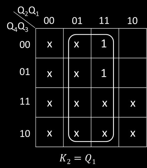
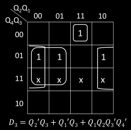
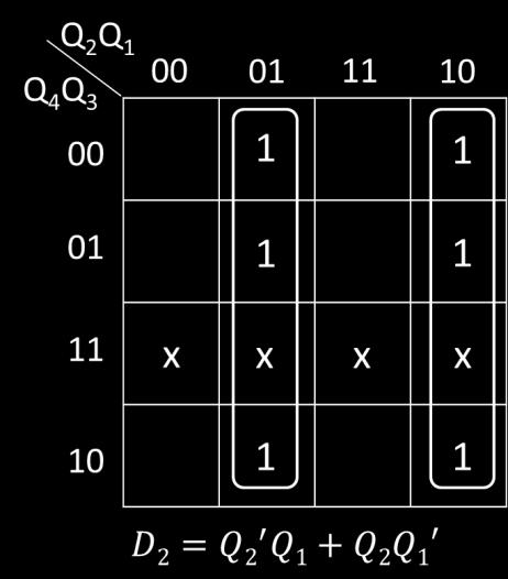
9 Step 4. Obtain the minimal expressions From excitation table, J 1 = K 1 = 1. K Maps for excitations J 3, K 3, J 2 and K 2 and their minimized form are as follows: Step 5. Draw the logic diagram Design a mod-12 Synchronous up counter using D-flipflop. A mod-12 counter requires 4 flip-flops. The counting sequence is 0000, 0001, 0010, 0011, 0100, 0101, 0110, 0111, 1000, 1001, 1010, 1011,
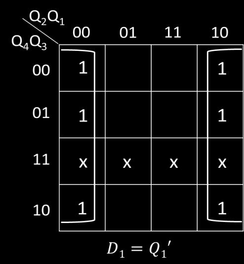
10 Step 2. Draw the state diagram: Step 3. Select the type of flip-flops and draw the excitation table: D flip-flops are selected and the excitation table of a given sequence counter using D flip-flops is shown below. PS NS Required excitations Q 4 Q 3 Q 2 Q 1 Q 4 Q 3 Q 2 Q 1 D 4 D 3 D 2 D Step 4. Obtain the minimal expressions K Maps for excitations D 4, D 3, D 2, and D 1 and their minimized form are as follows: 10


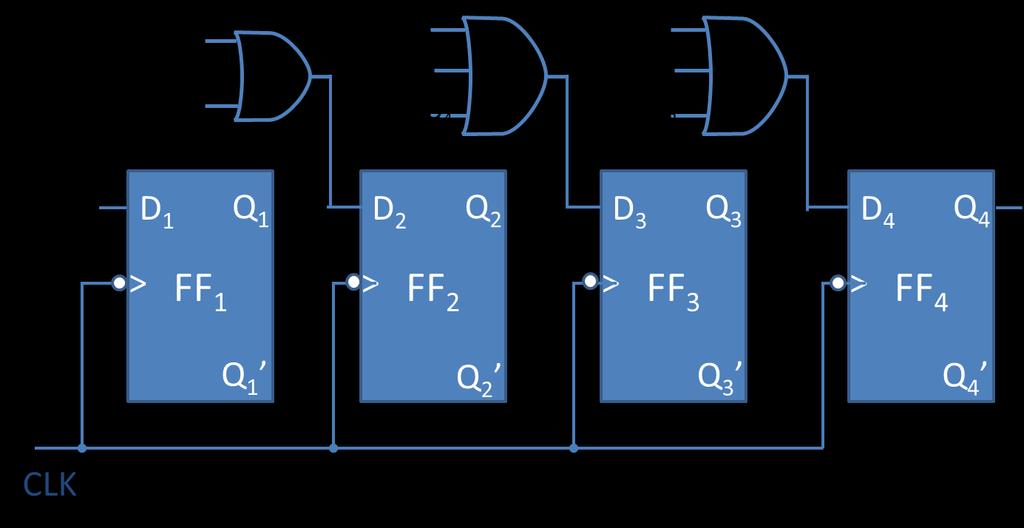
11 Step 5. Draw the logic diagram 11
Digital Logic Design - Chapter 5
 Digital Logic Design - Chapter 5 S. Design a 2-bit binary up counter a) using positive-edge-triggered D flip-flops. b) using positive-edge-triggered T flip-flops. c) using positive-edge-triggered JK flip-flops.
COE 202: Digital Logic Design Sequential Circuits Part 3. Dr. Ahmad Almulhem ahmadsm AT kfupm Phone: Office:
 COE 202: Digital Logic Design Sequential Circuits Part 3 Dr. Ahmad Almulhem Email: ahmadsm AT kfupm Phone: 860-7554 Office: 22-324 Objectives State Reduction and Assignment Design of Synchronous Sequential
Digital Logic Design - Chapter 4
 Digital Logic Design - Chapter 4 1. Analyze the latch circuit shown below by obtaining timing diagram for the circuit; include propagation delays. Y This circuit has two external input and one feedback
COE 202: Digital Logic Design Sequential Circuits Part 3. Dr. Ahmad Almulhem ahmadsm AT kfupm Phone: Office:
 COE 202: Digital Logic Design Sequential Circuits Part 3 Dr. Ahmad Almulhem Email: ahmadsm AT kfupm Phone: 860-7554 Office: 22-324 Objectives Important Design Concepts State Reduction and Assignment Design
Synchronous Sequential Logic. Chapter 5
 Synchronous Sequential Logic Chapter 5 Other Flip Flops D flip flops requires smallest number of gates. Thus, they are commonly used Other flip flops are JK flip flops T flip flops
CS221: Digital Design. Dr. A. Sahu. Indian Institute of Technology Guwahati
 CS221: Digital Design Counter&Registers Dr. A. Sahu DeptofComp.Sc.&Engg. Indian Institute of Technology Guwahati Outline Counter : Synchronous Vs Asynchronous Counter: Finite it State t Machine Mhi A register
Finite State Machine. By : Ali Mustafa
 Finite State Machine By : Ali Mustafa So Far We have covered the memory elements issue and we are ready to implement the sequential circuits. We need to know how to Deal(analyze) with a sequential circuit?
Chapter 5 Synchronous Sequential Logic
 Chapter 5 Synchronous Sequential Logic Sequential circuit: A circuit that includes memory elements. In this case the output depends not only on the current input but also on the past inputs. Memory A synchronous
The Design Procedure. Output Equation Determination - Derive output equations from the state table
 The Design Procedure Specification Formulation - Obtain a state diagram or state table State Assignment - Assign binary codes to the states Flip-Flop Input Equation Determination - Select flipflop types
ELE2120 Digital Circuits and Systems. Tutorial Note 9
 ELE2120 Digital Circuits and Systems Tutorial Note 9 Outline 1. Exercise(1) Sequential Circuit Analysis 2. Exercise (2) Sequential Circuit Analysis 3. Exercise (3) Sequential Circuit Analysis 4. Ref. Construction
King Fahd University of Petroleum and Minerals College of Computer Science and Engineering Computer Engineering Department
 King Fahd University of Petroleum and Minerals College of Computer Science and Engineering Computer Engineering Department Page of COE 22: Digital Logic Design (3--3) Term (Fall 22) Final Exam Sunday January
Lecture (08) Synchronous Sequential Logic
 Synchronous Sequential Logic") Lecture (08) Synchronous Sequential Logic By: Dr. Ahmed ElShafee ١ Dr. Ahmed ElShafee, ACU : Spring 2018, CSE303 Logic design II Analysis of Clocked Sequential Circuits The behavior of a clocked sequential
Lecture (08) Synchronous Sequential Logic By: Dr. Ahmed ElShafee ١ Dr. Ahmed ElShafee, ACU : Spring 2018, CSE303 Logic design II Analysis of Clocked Sequential Circuits The behavior of a clocked sequential
MAHALAKSHMI ENGINEERING COLLEGE TIRUCHIRAPALLI
 DEPARTMENT: ECE MAHALAKSHMI ENGINEERING COLLEGE TIRUCHIRAPALLI 6 QUESTION BANK SUBJECT NAME: DIGITAL ELECTRONICS UNIT : Design of Sequential Circuits PART A ( Marks). Draw the logic diagram 4: Multiplexer.(AUC
Roger L. Tokheim. Chapter 8 Counters Glencoe/McGraw-Hill
 Digital Electronics Principles & Applications Sixth Edition Roger L. Tokheim Chapter 8 Counters 2003 Glencoe/McGraw-Hill INTRODUCTION Overview of Counters Characteristics of Counters Ripple Up Counter
10/12/2016. An FSM with No Inputs Moves from State to State. ECE 120: Introduction to Computing. Eventually, the States Form a Loop
 University of Illinois at Urbana-Champaign Dept. of Electrical and Computer Engineering An FSM with No Inputs Moves from State to State What happens if an FSM has no inputs? ECE 120: Introduction to Computing
King Fahd University of Petroleum and Minerals College of Computer Science and Engineering Computer Engineering Department
 King Fahd University of Petroleum and Minerals College of Computer Science and Engineering Computer Engineering Department Page 1 of 13 COE 202: Digital Logic Design (3-0-3) Term 112 (Spring 2012) Final
Chapter 15 SEQUENTIAL CIRCUITS ANALYSIS, STATE- MINIMIZATION, ASSIGNMENT AND CIRCUIT IMPLEMENTATION
 Chapter 15 SEQUENTIAL CIRCUITS ANALYSIS, STATE- MINIMIZATION, ASSIGNMENT AND CIRCUIT IMPLEMENTATION Lesson 2 ANALYSIS OF CLOCKED SEQUENTIAL CIRCUIT Ch15L2- "Digital Principles and Design", Raj Kamal, Pearson
ECE/Comp Sci 352 Digital Systems Fundamentals. Charles R. Kime Section 2 Fall Logic and Computer Design Fundamentals
 University of Wisconsin - Madison ECE/Comp Sci 352 Digital Systems Fundamentals Charles R. Kime Section 2 Fall 2001 Lecture 5 Registers & Counters Part 2 Charles Kime Counters Counters are sequential circuits
Digital Circuits and Systems
 EE201: Digital Circuits and Systems 4 Sequential Circuits page 1 of 11 EE201: Digital Circuits and Systems Section 4 Sequential Circuits 4.1 Overview of Sequential Circuits: Definition The circuit whose
Sequential Circuit Analysis
 Sequential Circuit Analysis Last time we started talking about latches and flip-flops, which are basic one-bit memory units. Today we ll talk about sequential circuit analysis and design. First, we ll
ECE 341. Lecture # 3
 ECE 341 Lecture # 3 Instructor: Zeshan Chishti zeshan@ece.pdx.edu October 7, 2013 Portland State University Lecture Topics Counters Finite State Machines Decoders Multiplexers Reference: Appendix A of
CDA 3200 Digital Systems. Instructor: Dr. Janusz Zalewski Developed by: Dr. Dahai Guo Spring 2012
 CDA 3200 Digital Systems Instructor: Dr. Janusz Zalewski Developed by: Dr. Dahai Guo Spring 2012 Outline Registers and Register Transfers Shift Registers Design of Binary Counters Counters for Other Sequences
Digital Circuits ECS 371
 Digital Circuits ECS 371 Dr. Prapun Suksompong prapun@siit.tu.ac.th Lecture 18 Office Hours: BKD 3601-7 Monday 9:00-10:30, 1:30-3:30 Tuesday 10:30-11:30 1 Announcement Reading Assignment: Chapter 7: 7-1,
3 Logic Function Realization with MSI Circuits
 3 Logic Function Realization with MSI Circuits Half adder A half-adder is a combinational circuit with two binary inputs (augund and addend bits) and two binary outputs (sum and carry bits). It adds the
Counters. We ll look at different kinds of counters and discuss how to build them
 Counters We ll look at different kinds of counters and discuss how to build them These are not only examples of sequential analysis and design, but also real devices used in larger circuits 1 Introducing
Analysis and Design of Sequential Circuits: Examples
 COSC3410 Analysis and Design of Sequential Circuits: Examples J. C. Huang Department of Computer Science University of Houston Sequential machine slide 1 inputs combinational circuit outputs memory elements
Chapter 4 Part 2 Sequential Circuits
 University of Wisconsin - Madison ECE/Comp Sci 352 Digital Systems Fundamentals Kewal K. Saluja and Yu Hen Hu Spring 2002 Chapter 4 Part 2 Sequential Circuits Originals by: Charles R. Kime and Tom Kamisnski
DE58/DC58 LOGIC DESIGN DEC 2014
 Q.2 a. In a base-5 number system, 3 digit representations is used. Find out (i) Number of distinct quantities that can be represented.(ii) Representation of highest decimal number in base-5. Since, r=5
CSE 140: Components and Design Techniques for Digital Systems. Lecture 9: Sequential Networks: Implementation
 CSE 4: Components and Design Techniques for Digital Systems Lecture 9: Sequential Networks: Implementation CK Cheng Dept. of Computer Science and Engineering University of California, San Diego Implementation
CHW 261: Logic Design
 CHW 26: Logic Design Instructors: Prof. Hala Zayed Dr. Ahmed Shalaby http://www.bu.edu.eg/staff/halazayed4 http://bu.edu.eg/staff/ahmedshalaby4# Slide Digital Fundamentals CHAPTER 8 Counters Slide 2 Counting
ELCT201: DIGITAL LOGIC DESIGN
 ELCT201: DIGITAL LOGIC DESIGN Dr. Eng. Haitham Omran, haitham.omran@guc.edu.eg Dr. Eng. Wassim Alexan, wassim.joseph@guc.edu.eg Following the slides of Dr. Ahmed H. Madian Lecture 10 محرم 1439 ه Winter
Delhi Noida Bhopal Hyderabad Jaipur Lucknow Indore Pune Bhubaneswar Kolkata Patna Web: Ph:
 Serial : 5SP_CS_W_Digital Logic_598 Delhi Noida hopal Hyderabad Jaipur Lucknow Indore Pune hubaneswar Kolkata Patna Web: Email: info@madeeasy.in Ph: 452462 CLSS TEST 289 COMPUTER SCIENCE & IT Subject :
LOGIC CIRCUITS. Basic Experiment and Design of Electronics
 Basic Experiment and Design of Electronics LOGIC CIRCUITS Ho Kyung Kim, Ph.D. hokyung@pusan.ac.kr School of Mechanical Engineering Pusan National University Outline Combinational logic circuits Output
CSE 140 Midterm 2 Tajana Simunic Rosing. Spring 2008
 CSE 14 Midterm 2 Tajana Simunic Rosing Spring 28 Do not start the exam until you are told to. Turn off any cell phones or pagers. Write your name and PID at the top of every page. Do not separate the pages.
Digital Logic and Design (Course Code: EE222) Lecture 19: Sequential Circuits Contd..
 Lecture 19: Sequential Circuits Contd..") Indian Institute of Technology Jodhpur, Year 2017-2018 Digital Logic and Design (Course Code: EE222) Lecture 19: Sequential Circuits Contd.. Course Instructor: Shree Prakash Tiwari Email: sptiwari@iitj.ac.in
Indian Institute of Technology Jodhpur, Year 2017-2018 Digital Logic and Design (Course Code: EE222) Lecture 19: Sequential Circuits Contd.. Course Instructor: Shree Prakash Tiwari Email: sptiwari@iitj.ac.in
Design at the Register Transfer Level
 Week-7 Design at the Register Transfer Level Algorithmic State Machines Algorithmic State Machine (ASM) q Our design methodologies do not scale well to real-world problems. q 232 - Logic Design / Algorithmic
Q: Examine the relationship between X and the Next state. How would you describe this circuit? A: An inverter which is synched with a clock signal.
 /2/2 OF 7 Next, let s reverse engineer a T-Flip flop Prob. (Pg 529) Note that whenever T is equal to, there is a state change, otherwise, there isn t. In this circuit, (x) determines whether the output
Digital Fundamentals
 Digital Fundamentals Tenth Edition Floyd Chapter 9 Sections 9-1 thru 9-5 2009 Pearson Education, Upper 2008 Pearson Saddle River, Education NJ 07458. All Rights Reserved ET285 Agenda Week 2 Quiz 0: Covered
Lecture 17: Designing Sequential Systems Using Flip Flops
 EE210: Switching Systems Lecture 17: Designing Sequential Systems Using Flip Flops Prof. YingLi Tian April 11, 2019 Department of Electrical Engineering The City College of New York The City University
Delhi Noida Bhopal Hyderabad Jaipur Lucknow Indore Pune Bhubaneswar Kolkata Patna Web: Ph:
 Serial : S_CS_C_Digital Logic_588 Delhi Noida hopal Hyderabad Jaipur Lucknow Indore Pune hubaneswar Kolkata Patna Web: E-mail: info@madeeasy.in Ph: -56 CLASS TEST 8-9 COMPUTER SCIENCE & IT Subject : Digital
11.1 As mentioned in Experiment 10, sequential logic circuits are a type of logic circuit where the output of
 EE 2449 Experiment 11 Jack Levine and Nancy Warter-Perez CALIFORNIA STATE UNIVERSITY LOS ANGELES Department of Electrical and Computer Engineering EE-2449 Digital Logic Lab EXPERIMENT 11 SEQUENTIAL CIRCUITS
Lecture 8: Sequential Networks and Finite State Machines
 Lecture 8: Sequential Networks and Finite State Machines CSE 140: Components and Design Techniques for Digital Systems Spring 2014 CK Cheng, Diba Mirza Dept. of Computer Science and Engineering University
Clocked Synchronous State-machine Analysis
 Clocked Synchronous State-machine Analysis Given the circuit diagram of a state machine: Analyze the combinational logic to determine flip-flop input (excitation) equations: D i = F i (Q, inputs) The input
Sequential Circuits Sequential circuits combinational circuits state gate delay
 Sequential Circuits Sequential circuits are those with memory, also called feedback. In this, they differ from combinational circuits, which have no memory. The stable output of a combinational circuit
Lecture 10: Synchronous Sequential Circuits Design
 Lecture 0: Synchronous Sequential Circuits Design. General Form Input Combinational Flip-flops Combinational Output Circuit Circuit Clock.. Moore type has outputs dependent only on the state, e.g. ripple
WORKBOOK. Try Yourself Questions. Electrical Engineering Digital Electronics. Detailed Explanations of
 27 WORKBOOK Detailed Eplanations of Try Yourself Questions Electrical Engineering Digital Electronics Number Systems and Codes T : Solution Converting into decimal number system 2 + 3 + 5 + 8 2 + 4 8 +
EECS150 - Digital Design Lecture 23 - FSMs & Counters
 EECS150 - Digital Design Lecture 23 - FSMs & Counters April 8, 2010 John Wawrzynek Spring 2010 EECS150 - Lec22-counters Page 1 One-hot encoding of states. One FF per state. State Encoding Why one-hot encoding?
EE 209 Spiral 1 Exam Solutions Name:
 EE 29 Spiral Exam Solutions Name:.) Answer the following questions as True or False a.) A 4-to- multiplexer requires at least 4 select lines: true / false b.) An 8-to- mux and no other logic can be used
KUMARAGURU COLLEGE OF TECHNOLOGY COIMBATORE
 Estd-1984 KUMARAGURU COLLEGE OF TECHNOLOGY COIMBATORE 641 006 QUESTION BANK UNIT I PART A ISO 9001:2000 Certified 1. Convert (100001110.010) 2 to a decimal number. 2. Find the canonical SOP for the function
LOGIC CIRCUITS. Basic Experiment and Design of Electronics. Ho Kyung Kim, Ph.D.
 Basic Experiment and Design of Electronics LOGIC CIRCUITS Ho Kyung Kim, Ph.D. hokyung@pusan.ac.kr School of Mechanical Engineering Pusan National University Digital IC packages TTL (transistor-transistor
Reg. No. Question Paper Code : B.E./B.Tech. DEGREE EXAMINATION, NOVEMBER/DECEMBER Second Semester. Computer Science and Engineering
 Sp 6 Reg. No. Question Paper Code : 27156 B.E./B.Tech. DEGREE EXAMINATION, NOVEMBER/DECEMBER 2015. Second Semester Computer Science and Engineering CS 6201 DIGITAL PRINCIPLES AND SYSTEM DESIGN (Common
Sequential Logic Worksheet
 Sequential Logic Worksheet Concept Inventory: Notes: D-latch & the Dynamic Discipline D-register Timing constraints for sequential circuits Set-up and hold times for sequential circuits 6.004 Worksheet
 vidyarthiplus.com vidyarthiplus.com vidyarthiplus.com ANNA UNIVERSITY- COMBATORE B.E./ B.TECH. DEGREE EXAMINATION - JUNE 2009. ELECTRICAL & ELECTONICS ENGG. - FOURTH SEMESTER DIGITAL LOGIC CIRCUITS PART-A
Vidyalankar S.E. Sem. III [ETRX] Digital Circuits and Design Prelim Question Paper Solution
![Vidyalankar S.E. Sem. III [ETRX] Digital Circuits and Design Prelim Question Paper Solution](/thumbs/79/79145081.jpg "Vidyalankar S.E. Sem. III [ETRX] Digital Circuits and Design Prelim Question Paper Solution") S.E. Sem. III [ETRX] Digital Circuits and Design Prelim uestion Paper Solution. (a) Static Hazard Static hazards have two cases: static and static. static- hazard exists when the output variable should
S.E. Sem. III [ETRX] Digital Circuits and Design Prelim uestion Paper Solution. (a) Static Hazard Static hazards have two cases: static and static. static- hazard exists when the output variable should
Chapter 7. Sequential Circuits Registers, Counters, RAM
 Chapter 7. Sequential Circuits Registers, Counters, RAM Register - a group of binary storage elements suitable for holding binary info A group of FFs constitutes a register Commonly used as temporary storage
COE 202: Digital Logic Design Sequential Circuits Part 4. Dr. Ahmad Almulhem ahmadsm AT kfupm Phone: Office:
 COE 202: Digital Logic Design Sequential Circuits Part 4 Dr. Ahmad Almulhem Email: ahmadsm AT kfupm Phone: 860-7554 Office: 22-324 Objectives Registers Counters Registers 0 1 n-1 A register is a group
Introduction EE 224: INTRODUCTION TO DIGITAL CIRCUITS & COMPUTER DESIGN. Lecture 6: Sequential Logic 3 Registers & Counters 5/9/2010
 EE 224: INTROUCTION TO IGITAL CIRCUITS & COMPUTER ESIGN Lecture 6: Sequential Logic 3 Registers & Counters 05/10/2010 Avinash Kodi, kodi@ohio.edu Introduction 2 A Flip-Flop stores one bit of information
Philadelphia University Student Name: Student Number:
 Philadelphia University Student Name: Student Number: Faculty of Engineering Serial Number: Final Exam, Second Semester: 2015/2016 Dept. of Computer Engineering Course Title: Logic Circuits Date: 08/06/2016
Synchronous Sequential Logic
 1 IT 201 DIGITAL SYSTEMS DESIGN MODULE4 NOTES Synchronous Sequential Logic Sequential Circuits - A sequential circuit consists of a combinational circuit and a feedback through the storage elements in
Sample Test Paper - I
 Scheme G Sample Test Paper - I Course Name : Computer Engineering Group Marks : 25 Hours: 1 Hrs. Q.1) Attempt any THREE: 09 Marks a) Define i) Propagation delay ii) Fan-in iii) Fan-out b) Convert the following:
MAHALAKSHMI ENGINEERING COLLEGE TIRUCHIRAPALLI
 MAHALAKSHMI ENGINEERING COLLEGE TIRUCHIRAPALLI 6 DEPARTMENT: EEE QUESTION BANK SUBJECT NAME: DIGITAL LOGIC CIRCUITS SUBJECT CODE: EE55 SEMESTER IV UNIT : Design of Synchronous Sequential Circuits PART
COEN 312 DIGITAL SYSTEMS DESIGN - LECTURE NOTES Concordia University
 1 OEN 312 DIGIAL SYSEMS DESIGN - LEURE NOES oncordia University hapter 6: Registers and ounters NOE: For more examples and detailed description of the material in the lecture notes, please refer to the
Digital Logic Design. Midterm #2
 EECS: igital Logic esign r. nthony. Johnson s7m2s_dild7.fm - igital Logic esign Midterm #2 Problems Points. 5 2. 4 3. 6 Total 5 Was the exam fair? yes no EECS: igital Logic esign r. nthony. Johnson s7m2s_dild7.fm
Exam for Physics 4051, October 31, 2008
 Exam for Physics 45, October, 8 5 points - closed book - calculators allowed - show your work Problem : (6 Points) The 4 bit shift register circuit shown in Figure has been initialized to contain the following
EEE2135 Digital Logic Design
 EEE2135 Digital Logic Design Chapter 7. Sequential Circuits Design 서강대학교 전자공학과 1. Model of Sequential Circuits 1) Sequential vs. Combinational Circuits a. Sequential circuits: Outputs depend on both the
MOSIS REPORT. Spring MOSIS Report 1. MOSIS Report 2. MOSIS Report 3
 MOSIS REPORT Spring 2010 MOSIS Report 1 MOSIS Report 2 MOSIS Report 3 MOSIS Report 1 Design of 4-bit counter using J-K flip flop I. Objective The purpose of this project is to design one 4-bit counter
3. Complete the following table of equivalent values. Use binary numbers with a sign bit and 7 bits for the value
 EGC22 Digital Logic Fundamental Additional Practice Problems. Complete the following table of equivalent values. Binary. Octal 35.77 33.23.875 29.99 27 9 64 Hexadecimal B.3 D.FD B.4C 2. Calculate the following
CSCI 2150 Intro to State Machines
 CSCI 2150 Intro to State Machines Topic: Now that we've created flip-flops, let's make stuff with them Reading: igital Fundamentals sections 6.11 and 9.4 (ignore the JK flip-flop stuff) States Up until
Week-5. Sequential Circuit Design. Acknowledgement: Most of the following slides are adapted from Prof. Kale's slides at UIUC, USA.
 Week-5 Sequential Circuit Design Acknowledgement: Most of the following slides are adapted from Prof. Kale's slides at UIUC, USA. Storing a value: SR = 00 What if S = 0 and R = 0? The equations on the
EE 209 Logic Cumulative Exam Name:
 EE 209 Logic Cumulative Exam Name: 1.) Answer the following questions as True or False a.) A 4-to-1 multiplexer requires at least 4 select lines: true / false b.) An 8-to-1 mux and no other logi can be
EECS150 - Digital Design Lecture 17 - Sequential Circuits 3 (Counters)
") EECS150 - Digital Design Lecture 17 - Sequential Circuits 3 (Counters) March 19&21, 2002 John Wawrzynek Spring 2002 EECS150 - Lec13-seq3 version 2 Page 1 Counters Special sequential circuits (FSMs) that
EECS150 - Digital Design Lecture 17 - Sequential Circuits 3 (Counters) March 19&21, 2002 John Wawrzynek Spring 2002 EECS150 - Lec13-seq3 version 2 Page 1 Counters Special sequential circuits (FSMs) that
Simplify the following Boolean expressions and minimize the number of literals:
 Boolean Algebra Task 1 Simplify the following Boolean expressions and minimize the number of literals: 1.1 1.2 1.3 Task 2 Convert the following expressions into sum of products and product of sums: 2.1
課程名稱 : 數位邏輯設計 P-1/ /6/11
 課程名稱 : 數位邏輯設計 P-1/41 2012/6/11 extbook: igital esign, 4 th. Edition M. Morris Mano and Michael. iletti Prentice-Hall, Inc. 教師 : 蘇慶龍 INSRUOR : HING-LUNG SU E-mail: kevinsu@yuntech.edu.tw hapter 6 P-2/41
EECS Components and Design Techniques for Digital Systems. FSMs 9/11/2007
 EECS 150 - Components and Design Techniques for Digital Systems FSMs 9/11/2007 Sarah Bird Electrical Engineering and Computer Sciences University of California, Berkeley Slides borrowed from David Culler
Different encodings generate different circuits
 FSM State Encoding Different encodings generate different circuits no easy way to find best encoding with fewest logic gates or shortest propagation delay. Binary encoding: K states need log 2 K bits i.e.,
ELEC Digital Logic Circuits Fall 2014 Sequential Circuits (Chapter 6) Finite State Machines (Ch. 7-10)
 Finite State Machines (Ch. 7-10)") ELEC 2200-002 Digital Logic Circuits Fall 2014 Sequential Circuits (Chapter 6) Finite State Machines (Ch. 7-10) Vishwani D. Agrawal James J. Danaher Professor Department of Electrical and Computer Engineering
ELEC 2200-002 Digital Logic Circuits Fall 2014 Sequential Circuits (Chapter 6) Finite State Machines (Ch. 7-10) Vishwani D. Agrawal James J. Danaher Professor Department of Electrical and Computer Engineering
Philadelphia University Faculty of Engineering
 Philadelphia University Faculty of Engineering Marking Scheme Exam Paper BSc CE Logic Circuits (630211) Final Exam First semester ate: 03/02/2019 Section 1 Weighting 40% of the module total Lecturer: Coordinator:
Digital Fundamentals
 Digital Fundamentals Tenth Edition Floyd hapter 8 Modified by Yuttapong Jiraraksopakun Floyd, Digital Fundamentals, 10 th 2008 Pearson Education ENE, KMUTT ed 2009 ounting in Binary As you know, the binary
Chapter 7 Sequential Logic
 Chapter 7 Sequential Logic SKEE2263 Digital Systems Mun im/ismahani/izam {munim@utm.my,e-izam@utm.my,ismahani@fke.utm.my} March 28, 2016 Table of Contents 1 Intro 2 Bistable Circuits 3 FF Characteristics
Layout of 7400-series Chips Commonly Used in. CDA 3101: Introduction to Computer Hardware and Organization
 Layout of 400-series Chips Commonly Used in CDA 30: Introduction to Computer Hardware and Organization Charles N. Winton Department of Computer and Information Sciences University of North Florida 999
Synchronous Sequential Circuit Design. Digital Computer Design
 Synchronous Sequential Circuit Design Digital Computer Design Races and Instability Combinational logic has no cyclic paths and no races If inputs are applied to combinational logic, the outputs will always
Sequential Logic Design
 221: igital esign http://jatinga.iitg.ernet.in/~asahu/cs221 equential Logic esign (FF& egister) A. ahu ept of omp. c. & ngg. ndian nstitute of echnology Guwahati Outline FF: haracterization able and quation,,
Digital Electronic Meters
 Digital Electronic Meters EIE 240 Electrical and Electronic Measurement May 1, 2015 1 Digital Signal Binary or two stages: 0 (Low voltage 0-3 V) 1 (High voltage 4-5 V) Binary digit is called bit. Group
Chapter 6. Synchronous Sequential Circuits
 Chapter 6 Synchronous Sequential Circuits In a combinational circuit, the values of the outputs are determined solely by the present values of its inputs. In a sequential circuit, the values of the outputs
Chapter 3 Digital Logic Structures
 Chapter 3 Digital Logic Structures Original slides from Gregory Byrd, North Carolina State University Modified by C. Wilcox, M. Strout, Y. Malaiya Colorado State University Computing Layers Problems Algorithms
Chapter 7. Synchronous Sequential Networks. Excitation for
 Chapter 7 Excitation for Synchronous Sequential Networks J. C. Huang, 2004 igital Logic esign 1 Structure of a clocked synchronous sequential network Mealy model of a clocked synchronous sequential network
Review for Final Exam
 CSE140: Components and Design Techniques for Digital Systems Review for Final Exam Mohsen Imani CAPE Please submit your evaluations!!!! RTL design Use the RTL design process to design a system that has
Shift Register Counters
 Shift Register Counters Shift register counter: a shift register with the serial output connected back to the serial input. They are classified as counters because they give a specified sequence of states.
Synchronous Sequential Logic Part I. BME208 Logic Circuits Yalçın İŞLER
 Synchronous Sequential Logic Part I BME28 Logic Circuits Yalçın İŞLER islerya@yahoo.com http://me.islerya.com Sequential Logic Digital circuits we have learned, so far, have been combinational no memory,
Exercise booklet - Logic
 Name: Class: Date:......... Exercise booklet Logic BCD Counter Worksheet with excercises and repetitive tasks for students and learners Find the seven logic gates in the puzzle. The words can be hidden
( c) Give logic symbol, Truth table and circuit diagram for a clocked SR flip-flop. A combinational circuit is defined by the function
 Give logic symbol, Truth table and circuit diagram for a clocked SR flip-flop. A combinational circuit is defined by the function") Question Paper Digital Electronics (EE-204-F) MDU Examination May 2015 1. (a) represent (32)10 in (i) BCD 8421 code (ii) Excess-3 code (iii) ASCII code (b) Design half adder using only NAND gates. ( c)
Question Paper Digital Electronics (EE-204-F) MDU Examination May 2015 1. (a) represent (32)10 in (i) BCD 8421 code (ii) Excess-3 code (iii) ASCII code (b) Design half adder using only NAND gates. ( c)
EECS150 - Digital Design Lecture 18 - Counters
 EECS150 - Digital Design Lecture 18 - Counters October 24, 2002 John Wawrzynek Fall 2002 EECS150 - Lec18-counters Page 1 Counters Special sequential circuits (FSMs) that sequence though a set outputs.
EECS150 - Digital Design Lecture 18 - Counters
 EECS50 - Digital Design Lecture 8 - Counters October 24, 2002 John Wawrzynek Fall 2002 EECS50 - Lec8-counters Page Counters Special sequential circuits (FSMs) that sequence though a set outputs. Examples:
S.Y. Diploma : Sem. III [DE/ED/EI/EJ/EN/ET/EV/EX/IC/IE/IS/IU/MU] Principles of Digital Techniques
![S.Y. Diploma : Sem. III [DE/ED/EI/EJ/EN/ET/EV/EX/IC/IE/IS/IU/MU] Principles of Digital Techniques](/thumbs/82/86792063.jpg "S.Y. Diploma : Sem. III [DE/ED/EI/EJ/EN/ET/EV/EX/IC/IE/IS/IU/MU] Principles of Digital Techniques") S.Y. Diploma : Sem. III [DE/ED/EI/EJ/EN/ET/EV/EX/IC/IE/IS/IU/MU] Principles of Digital Techniques Time: 3 Hrs.] Prelim Question Paper Solution [Marks : 100 Q.1(a) Attempt any SIX of the following : [12]
S.Y. Diploma : Sem. III [DE/ED/EI/EJ/EN/ET/EV/EX/IC/IE/IS/IU/MU] Principles of Digital Techniques Time: 3 Hrs.] Prelim Question Paper Solution [Marks : 100 Q.1(a) Attempt any SIX of the following : [12]
ENGG 1203 Tutorial _03 Laboratory 3 Build a ball counter. Lab 3. Lab 3 Gate Timing. Lab 3 Steps in designing a State Machine. Timing diagram of a DFF
 ENGG 1203 Tutorial _03 Laboratory 3 Build a ball counter Timing diagram of a DFF Lab 3 Gate Timing difference timing for difference kind of gate, cost dependence (1) Setup Time = t2-t1 (2) Propagation
PGT104 Digital Electronics. PGT104 Digital Electronics
 1 Part 6 Sequential Logic ircuits Disclaimer: Most of the contents (if not all) are extracted from resources available for Digital Fundamentals 10 th Edition 2 Basic Shift Register Operations A shift register
Sequential Logic Circuits
 Chapter 4 Sequential Logic Circuits 4 1 The defining characteristic of a combinational circuit is that its output depends only on the current inputs applied to the circuit. The output of a sequential circuit,
Vidyalankar S.E. Sem. III [EXTC] Digital Electronics Prelim Question Paper Solution ABCD ABCD ABCD ABCD ABCD ABCD ABCD ABCD = B
![Vidyalankar S.E. Sem. III [EXTC] Digital Electronics Prelim Question Paper Solution ABCD ABCD ABCD ABCD ABCD ABCD ABCD ABCD = B](/thumbs/84/91058397.jpg "Vidyalankar S.E. Sem. III [EXTC] Digital Electronics Prelim Question Paper Solution ABCD ABCD ABCD ABCD ABCD ABCD ABCD ABCD = B") . (a). (b). (c) S.E. Sem. III [EXTC] igital Electronics Prelim Question Paper Solution ABC ABC ABC ABC ABC ABC ABC ABC = B LHS = ABC ABC ABC ABC ABC ABC ABC ABC But ( ) = = ABC( ) ABC( ) ABC( ) ABC( )
. (a). (b). (c) S.E. Sem. III [EXTC] igital Electronics Prelim Question Paper Solution ABC ABC ABC ABC ABC ABC ABC ABC = B LHS = ABC ABC ABC ABC ABC ABC ABC ABC But ( ) = = ABC( ) ABC( ) ABC( ) ABC( )
Sequential logic and design
 Principles Of Digital Design Sequential logic and design Analysis State-based (Moore) Input-based (Mealy) FSM definition Synthesis State minimization Encoding Optimization and timing Copyright 20-20by
State Machines ELCTEC-131
 State Machines ELCTEC-131 Switch Debouncer A digital circuit that is used to remove the mechanical bounce from a switch contact. When a switch is closed, the contacts bounce from open to closed to cause