When water (fluid) flows in a pipe, for example from point A to point B, pressure drop will occur due to the energy losses (major and minor losses).
|
|
|
- Scott O’Connor’
- 6 years ago
- Views:
Transcription
1 PRESSURE DROP AND OSSES IN PIPE When water (luid) lows in a pipe, or example rom point A to point B, pressure drop will occur due to the energy losses (major and minor losses). A B Bernoulli equation: PA A PB B + + za + + zb + h ρg g ρg g I pipe diameter is the same, the velocity remain constant along the pipe. A B I the height is the same, the potential energy can be neglected. za zb z
2 Pressure drop could be determine as: + g g D h g P P B A ρ where is a riction actor, and need to be determine.for laminar low, Re 64 For turbulent low, need to be determined using Moody chart The relative pipe roughness, D ε need to be measured.
3 COEBROO-WHITE EUATION This is an equation to ind the value o riction actor,, or turbulent low. log 0 ε D Re D ε Re Darcy riction actor, dimensionless Inside diameter o pipe in meter Pipe surace roughness in meter Reynolds number, dimensionless From this equation, Moody chart was developed. Moody chart consist three (3) major parts;. aminar region. Transition region 3. Turbulent region
4
5 aminar region The value o riction actor is proportional with Reynolds number. 64 Re A straight line could be plotted on the Moody chart. Transition region Friction will be aected with Reynolds number and internal pipe roughness. Complete turbulent region log 0 ε D Re From equation above, high Reynolds number could lead to a very small value. It is means that only internal pipe surace roughness would inluence the riction value. In Moody chart, the graph line would become a horizontal straight line.
6 Example Water lows through mm pipeline. It has 4.55 mm wall thickness. Flowrate is.36 m 3 /min. Assuming a pipe roughness o mm, calculate the riction actor and head loss due to riction in 305 m o pipe length. Flowrate,.36 m 3 /min 0.89 m 3 /s Inner diameter (9.55) mm mm ρd 5 Re μ ε D From Moody chart, 0.05 PA PB ρg D g.54 (m) P A P B 5. kpa
7 Example A concrete pipe, m inside diameter, is used to transport water rom a pumping acility to a storage tank 5km away. Neglecting any dierence in elevations, calculate the riction actor and pressure loss due to riction at a low rate o 34,000m 3 /h. Assume a pipe roughness o 0.05mm. I a delivery pressure o 4kPa must be maintained at the delivery point and the storage tank is at an elevation o 00m above that o the pumping acility, calculate the pressure required at the pumping acility at the given low rate, using the Moody chart.
8 HAZEN-WIIAMS EUATION A more popular approach to the calculation o head loss in water piping systems is the use o the Hazen-Williams equation. In this method a coeicient C known as the Hazen-Williams C actor is used to account or the internal pipe roughness o eiciency. Unlike the Moody chart or the Colebrook-White equation, the Hazen-Williams equation does not require use o the Reynolds number or viscosity o water to calculate the head loss due to riction. The Hazen-Williams equation or head loss is expressed as ollows: For SI unit: h D C.85 h Frictional head loss in m ength o pipe in m D Inside diameter o pipe in m Flow rate in m 3 /s C Hazen-Williams C actor or roughness coeicient, dimensionless.
9 For British unit: h D C.85 h Frictional head loss in t ength o pipe in t D Inside diameter o pipe in t Flow rate in t 3 /s C Hazen-Williams C actor or roughness coeicient, dimensionless. Note: Above equation can be rearrange a ollows: S h where S is the hydraulic slope
10 Commonly used values o the Hazen-Williams C actor or various applications. Pipe material C actor Smooth pipes (all metal) Cast iron (old) 00 Iron (worn/pitted) Polyvinyl chloride (PC) 50 Brick 00 Smooth wood 0 Smooth masonry 0 itriied clay 0
11 MANNING EUATION The Manning equation was originally developed or use in open channel low o water. It is also sometimes used in pipe low. The Manning equation uses the Manning index, n or roughness coeicient. For SI unit: AR n 3 h Flow rate, m 3 /s A cross sectional area o pipe, m R hydraulic radius (D/4 or circular pipes lowing ull) n Manning index, or roughness coeicient, dimensionless D Inside diameter o pipe, m h Friction loss, m ength o pipe, m
12 For British unit:.486 AR n 3 h Flow rate, t 3 /s A cross sectional area o pipe, t R hydraulic radius (D/4 or circular pipes lowing ull) n Manning index, or roughness coeicient, dimensionless D Inside diameter o pipe, t h Friction loss, t ength o pipe, t Example o Manning index Pipe material Resistance actor PC ery smooth 0.00 Cement-lined ductile iron 0.0 New cast iron, welded steel 0.04 Old cast iron, brick 0.00 Badly corroded cast iron Wood, concrete 0.06 Clay, new riveted steel 0.07 Canals cut through rock Earth canals average condition 0.03 Rivers in good conditions 0.030
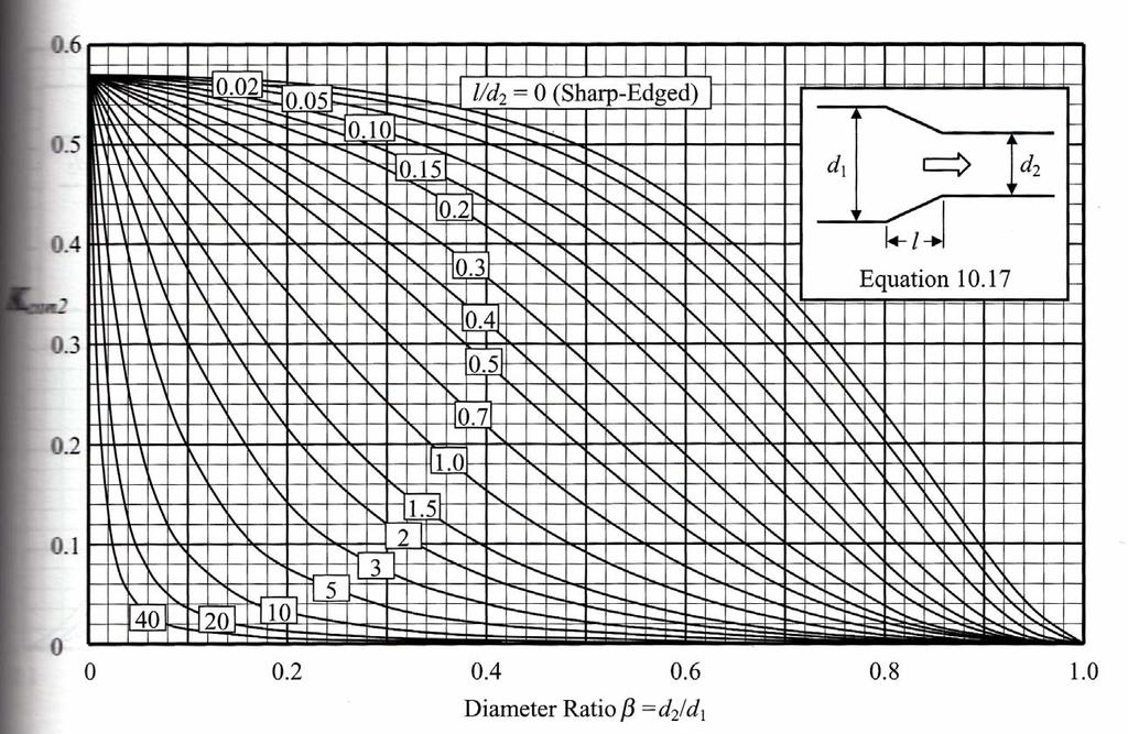
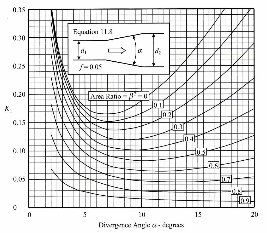
13 MINOR OSSES Minor losses in a water pipeline are classiied as those pressure drops that are associated with piping components such as valves and itting. There are included: Elbow and tees Pipe diameter enlargement / reduction Nozzle Entrance / exit losses They are relatively small compared to riction loss in a straight length o pipe. Minor loss g Where is a resistance actor. It must be noted that this way calculating the minor losses is valid only in turbulent low. No data are available or laminar low. Some engineers use the equivalent length to determine minor losses.
14
15
16
17 SIMPIFICATION OF MAJOR OSS CACUATION Head loss due to riction; g D h From continuity equation, D A 4 π 4 D π 4 6 D π Head loss equation can be written as: 5 6 g D g D h π h Usually, or turbulent low, h

 A")
18 Major losses in series pipe Flow rate is constant A B C Major losses keep increasing h h A + h B + h C ( + + ) A B c
19 Major losses in parallel pipe Flow rate is constant at inlet and outlet (only) A B However, low rate or pipe, and 3 are dierent. A B Major losses are constant or pipe, and 3. h h h h3
20 h h 3 B A h h h h
HEADLOSS ESTIMATION. Mekanika Fluida 1 HST
 HEADLOSS ESTIMATION Mekanika Fluida HST Friction Factor : Major losses Laminar low Hagen-Poiseuille Turbulent (Smoot, Transition, Roug) Colebrook Formula Moody diagram Swamee-Jain 3 Laminar Flow Friction
Chapter 3 Water Flow in Pipes
 The Islamic University o Gaza Faculty o Engineering Civil Engineering Department Hydraulics - ECI 33 Chapter 3 Water Flow in Pipes 3. Description o A Pipe Flow Water pipes in our homes and the distribution
FE Fluids Review March 23, 2012 Steve Burian (Civil & Environmental Engineering)
") Topic: Fluid Properties 1. If 6 m 3 of oil weighs 47 kn, calculate its specific weight, density, and specific gravity. 2. 10.0 L of an incompressible liquid exert a force of 20 N at the earth s surface.
Topic: Fluid Properties 1. If 6 m 3 of oil weighs 47 kn, calculate its specific weight, density, and specific gravity. 2. 10.0 L of an incompressible liquid exert a force of 20 N at the earth s surface.
Review of pipe flow: Friction & Minor Losses
 ENVE 204 Lecture -1 Review of pipe flow: Friction & Minor Losses Assist. Prof. Neslihan SEMERCİ Marmara University Department of Environmental Engineering Important Definitions Pressure Pipe Flow: Refers
OE4625 Dredge Pumps and Slurry Transport. Vaclav Matousek October 13, 2004
 OE465 Vaclav Matousek October 13, 004 1 Dredge Vermelding Pumps onderdeel and Slurry organisatie Transport OE465 Vaclav Matousek October 13, 004 Dredge Vermelding Pumps onderdeel and Slurry organisatie
1-Reynold s Experiment
 Lect.No.8 2 nd Semester Flow Dynamics in Closed Conduit (Pipe Flow) 1 of 21 The flow in closed conduit ( flow in pipe ) is differ from this occur in open channel where the flow in pipe is at a pressure
Hydraulics and hydrology
 Hydraulics and hydrology - project exercises - Class 4 and 5 Pipe flow Discharge (Q) (called also as the volume flow rate) is the volume of fluid that passes through an area per unit time. The discharge
Chapter (3) Water Flow in Pipes
 Water Flow in Pipes") Chapter (3) Water Flow in Pipes Water Flow in Pipes Bernoulli Equation Recall fluid mechanics course, the Bernoulli equation is: P 1 ρg + v 1 g + z 1 = P ρg + v g + z h P + h T + h L Here, we want to study
Chapter (3) Water Flow in Pipes Water Flow in Pipes Bernoulli Equation Recall fluid mechanics course, the Bernoulli equation is: P 1 ρg + v 1 g + z 1 = P ρg + v g + z h P + h T + h L Here, we want to study
FLOW FRICTION CHARACTERISTICS OF CONCRETE PRESSURE PIPE
 11 ACPPA TECHNICAL SERIES FLOW FRICTION CHARACTERISTICS OF CONCRETE PRESSURE PIPE This paper presents formulas to assist in hydraulic design of concrete pressure pipe. There are many formulas to calculate
Reynolds, an engineering professor in early 1880 demonstrated two different types of flow through an experiment:
 7 STEADY FLOW IN PIPES 7.1 Reynolds Number Reynolds, an engineering professor in early 1880 demonstrated two different types of flow through an experiment: Laminar flow Turbulent flow Reynolds apparatus
Hydraulics. B.E. (Civil), Year/Part: II/II. Tutorial solutions: Pipe flow. Tutorial 1
, Year/Part: II/II. Tutorial solutions: Pipe flow. Tutorial 1") Hydraulics B.E. (Civil), Year/Part: II/II Tutorial solutions: Pipe flow Tutorial 1 -by Dr. K.N. Dulal Laminar flow 1. A pipe 200mm in diameter and 20km long conveys oil of density 900 kg/m 3 and viscosity
Hydraulics B.E. (Civil), Year/Part: II/II Tutorial solutions: Pipe flow Tutorial 1 -by Dr. K.N. Dulal Laminar flow 1. A pipe 200mm in diameter and 20km long conveys oil of density 900 kg/m 3 and viscosity
LECTURE 6- ENERGY LOSSES IN HYDRAULIC SYSTEMS SELF EVALUATION QUESTIONS AND ANSWERS
 LECTURE 6- ENERGY LOSSES IN HYDRAULIC SYSTEMS SELF EVALUATION QUESTIONS AND ANSWERS 1. What is the head loss ( in units of bars) across a 30mm wide open gate valve when oil ( SG=0.9) flow through at a
FLUID MECHANICS D203 SAE SOLUTIONS TUTORIAL 2 APPLICATIONS OF BERNOULLI SELF ASSESSMENT EXERCISE 1
 FLUID MECHANICS D203 SAE SOLUTIONS TUTORIAL 2 APPLICATIONS OF BERNOULLI SELF ASSESSMENT EXERCISE 1 1. A pipe 100 mm bore diameter carries oil of density 900 kg/m3 at a rate of 4 kg/s. The pipe reduces
Chapter 8: Flow in Pipes
 Objectives 1. Have a deeper understanding of laminar and turbulent flow in pipes and the analysis of fully developed flow 2. Calculate the major and minor losses associated with pipe flow in piping networks
Mechanical Engineering Programme of Study
 Mechanical Engineering Programme of Study Fluid Mechanics Instructor: Marios M. Fyrillas Email: eng.fm@fit.ac.cy SOLVED EXAMPLES ON VISCOUS FLOW 1. Consider steady, laminar flow between two fixed parallel
Pipe Flow. Lecture 17
 Pipe Flow Lecture 7 Pipe Flow and the Energy Equation For pipe flow, the Bernoulli equation alone is not sufficient. Friction loss along the pipe, and momentum loss through diameter changes and corners
Chapter 10 Flow in Conduits
 Chapter 10 Flow in Conduits 10.1 Classifying Flow Laminar Flow and Turbulent Flow Laminar flow Unpredictable Turbulent flow Near entrance: undeveloped developing flow In developing flow, the wall shear
PIPE FLOW. The Energy Equation. The first law of thermodynamics for a system is, in words = +
 The Energy Equation PIPE FLOW The first law of thermodynamics for a system is, in words Time rate of increase of the total storage energy of the t Net time rate of energy addition by heat transfer into
Chapter (3) Water Flow in Pipes
 Water Flow in Pipes") Chapter (3) Water Flow in Pipes Water Flow in Pipes Bernoulli Equation Recall fluid mechanics course, the Bernoulli equation is: P 1 ρg + v 1 g + z 1 = P ρg + v g + z h P + h T + h L Here, we want to study
Chapter (3) Water Flow in Pipes Water Flow in Pipes Bernoulli Equation Recall fluid mechanics course, the Bernoulli equation is: P 1 ρg + v 1 g + z 1 = P ρg + v g + z h P + h T + h L Here, we want to study
Chapter 8: Flow in Pipes
 8-1 Introduction 8-2 Laminar and Turbulent Flows 8-3 The Entrance Region 8-4 Laminar Flow in Pipes 8-5 Turbulent Flow in Pipes 8-6 Fully Developed Pipe Flow 8-7 Minor Losses 8-8 Piping Networks and Pump
ME 305 Fluid Mechanics I. Part 8 Viscous Flow in Pipes and Ducts. Flow in Pipes and Ducts. Flow in Pipes and Ducts (cont d)
") ME 305 Fluid Mechanics I Flow in Pipes and Ducts Flow in closed conduits (circular pipes and non-circular ducts) are very common. Part 8 Viscous Flow in Pipes and Ducts These presentations are prepared
ME 305 Fluid Mechanics I Flow in Pipes and Ducts Flow in closed conduits (circular pipes and non-circular ducts) are very common. Part 8 Viscous Flow in Pipes and Ducts These presentations are prepared
Piping Systems and Flow Analysis (Chapter 3)
") Piping Systems and Flow Analysis (Chapter 3) 2 Learning Outcomes (Chapter 3) Losses in Piping Systems Major losses Minor losses Pipe Networks Pipes in series Pipes in parallel Manifolds and Distribution
Piping Systems and Flow Analysis (Chapter 3) 2 Learning Outcomes (Chapter 3) Losses in Piping Systems Major losses Minor losses Pipe Networks Pipes in series Pipes in parallel Manifolds and Distribution
Chapter 6. Losses due to Fluid Friction
 Chapter 6 Losses due to Fluid Friction 1 Objectives To measure the pressure drop in the straight section of smooth, rough, and packed pipes as a function of flow rate. To correlate this in terms of the
Hydraulic Design Of Polyethylene Pipes
 Hydraulic Design Of Polyethylene Pipes Waters & Farr polyethylene pipes offer a hydraulically smooth bore that provides excellent flow characteristics. Other advantages of Waters & Farr polyethylene pipes,
Chapter 6. Losses due to Fluid Friction
 Chapter 6 Losses due to Fluid Friction 1 Objectives ä To measure the pressure drop in the straight section of smooth, rough, and packed pipes as a function of flow rate. ä To correlate this in terms of
ACCOUNTING FOR FRICTION IN THE BERNOULLI EQUATION FOR FLOW THROUGH PIPES
 ACCOUNTING FOR FRICTION IN THE BERNOULLI EQUATION FOR FLOW THROUGH PIPES Some background information first: We have seen that a major limitation of the Bernoulli equation is that it does not account for
FACULTY OF CHEMICAL & ENERGY ENGINEERING FLUID MECHANICS LABORATORY TITLE OF EXPERIMENT: MINOR LOSSES IN PIPE (E4)
") FACULTY OF CHEMICAL & ENERGY ENGINEERING FLUID MECHANICS LABORATORY TITLE OF EXPERIMENT: MINOR LOSSES IN PIPE (E4) 1 1.0 Objectives The objective of this experiment is to calculate loss coefficient (K
FACULTY OF CHEMICAL & ENERGY ENGINEERING FLUID MECHANICS LABORATORY TITLE OF EXPERIMENT: MINOR LOSSES IN PIPE (E4) 1 1.0 Objectives The objective of this experiment is to calculate loss coefficient (K
Chapter 8 Flow in Pipes. Piping Systems and Pump Selection
 Piping Systems and Pump Selection 8-6C For a piping system that involves two pipes o dierent diameters (but o identical length, material, and roughness connected in series, (a the low rate through both
Used to estimate energy loss due to friction in pipe. D = internal diameter of pipe (feet) L = length of pipe (feet) Penn State-Harrisburg
 L = length of pipe (feet) Penn State-Harrisburg") Module b: Flow in Pipes Darcy-Weisbac Robert Pitt University o Alabama and Sirley Clark Penn State-Harrisburg Darcy-Weisbac can be written or low (substitute V Q/A, were A (π/4)d in te above equation):
Module b: Flow in Pipes Darcy-Weisbac Robert Pitt University o Alabama and Sirley Clark Penn State-Harrisburg Darcy-Weisbac can be written or low (substitute V Q/A, were A (π/4)d in te above equation):
Major and Minor Losses
 Abstract Major and Minor Losses Caitlyn Collazo, Team 2 (1:00 pm) A Technovate fluid circuit system was used to determine the pressure drop across a pipe section and across an orifice. These pressure drops
A Model Answer for. Problem Set #7
 A Model Answer for Problem Set #7 Pipe Flow and Applications Problem.1 A pipeline 70 m long connects two reservoirs having a difference in water level of 6.0 m. The pipe rises to a height of 3.0 m above
12d Model. Civil and Surveying Software. Version 7. Drainage Analysis Module Hydraulics. Owen Thornton BE (Mech), 12d Model Programmer
, 12d Model Programmer") 1d Model Civil and Surveying Sotware Version 7 Drainage Analysis Module Hydraulics Owen Thornton BE (Mech), 1d Model Programmer owen.thornton@1d.com 9 December 005 Revised: 10 January 006 8 February 007
1d Model Civil and Surveying Sotware Version 7 Drainage Analysis Module Hydraulics Owen Thornton BE (Mech), 1d Model Programmer owen.thornton@1d.com 9 December 005 Revised: 10 January 006 8 February 007
ME 305 Fluid Mechanics I. Chapter 8 Viscous Flow in Pipes and Ducts
 ME 305 Fluid Mechanics I Chapter 8 Viscous Flow in Pipes and Ducts These presentations are prepared by Dr. Cüneyt Sert Department of Mechanical Engineering Middle East Technical University Ankara, Turkey
Calculation of Pipe Friction Loss
 Doc.No. 6122-F3T071 rev.2 Calculation of Pipe Friction Loss Engineering Management Group Development Planning Department Standard Pump Business Division EBARA corporation October 16th, 2013 1 / 33 2 /
Applied Fluid Mechanics
 Applied Fluid Mechanics 1. The Nature of Fluid and the Study of Fluid Mechanics 2. Viscosity of Fluid 3. Pressure Measurement 4. Forces Due to Static Fluid 5. Buoyancy and Stability 6. Flow of Fluid and
CVE 372 HYDROMECHANICS EXERCISE PROBLEMS
 VE 37 HYDROMEHNIS EXERISE PROLEMS 1. pump that has the characteristic curve shown in the accompanying graph is to be installed in the system shown. What will be the discharge of water in the system? Take
Chapter 7 FLOW THROUGH PIPES
 Chapter 7 FLOW THROUGH PIPES 7-1 Friction Losses of Head in Pipes 7-2 Secondary Losses of Head in Pipes 7-3 Flow through Pipe Systems 48 7-1 Friction Losses of Head in Pipes: There are many types of losses
2 Internal Fluid Flow
 Internal Fluid Flow.1 Definitions Fluid Dynamics The study of fluids in motion. Static Pressure The pressure at a given point exerted by the static head of the fluid present directly above that point.
FLOW IN CONDUITS. Shear stress distribution across a pipe section. Chapter 10
 Chapter 10 Shear stress distribution across a pipe section FLOW IN CONDUITS For steady, uniform flow, the momentum balance in s for the fluid cylinder yields Fluid Mechanics, Spring Term 2010 Velocity
STEADY FLOW THROUGH PIPES DARCY WEISBACH EQUATION FOR FLOW IN PIPES. HAZEN WILLIAM S FORMULA, LOSSES IN PIPELINES, HYDRAULIC GRADE LINES AND ENERGY
 STEADY FLOW THROUGH PIPES DARCY WEISBACH EQUATION FOR FLOW IN PIPES. HAZEN WILLIAM S FORMULA, LOSSES IN PIPELINES, HYDRAULIC GRADE LINES AND ENERGY LINES 1 SIGNIFICANCE OF CONDUITS In considering the convenience
Viscous Flow in Ducts
 Dr. M. Siavashi Iran University of Science and Technology Spring 2014 Objectives 1. Have a deeper understanding of laminar and turbulent flow in pipes and the analysis of fully developed flow 2. Calculate
Lesson 37 Transmission Of Air In Air Conditioning Ducts
 Lesson 37 Transmission Of Air In Air Conditioning Ducts Version 1 ME, IIT Kharagpur 1 The specific objectives of this chapter are to: 1. Describe an Air Handling Unit (AHU) and its functions (Section 37.1).
Applied Fluid Mechanics
 Applied Fluid Mechanics 1. The Nature of Fluid and the Study of Fluid Mechanics 2. Viscosity of Fluid 3. Pressure Measurement 4. Forces Due to Static Fluid 5. Buoyancy and Stability 6. Flow of Fluid and
s and FE X. A. Flow measurement B. properties C. statics D. impulse, and momentum equations E. Pipe and other internal flow 7% of FE Morning Session I
 Fundamentals of Engineering (FE) Exam General Section Steven Burian Civil & Environmental Engineering October 26, 2010 s and FE X. A. Flow measurement B. properties C. statics D. impulse, and momentum
Lesson 6 Review of fundamentals: Fluid flow
 Lesson 6 Review of fundamentals: Fluid flow The specific objective of this lesson is to conduct a brief review of the fundamentals of fluid flow and present: A general equation for conservation of mass
PIPING SYSTEMS. Pipe and Tubing Standards Sizes for pipes and tubes are standardized. Pipes are specified by a nominal diameter and a schedule number.
 PIPING SYSTEMS In this chapter we will review some of the basic concepts associated with piping systems. Topics that will be considered in this chapter are - Pipe and tubing standards - Effective and hydraulic
Water Circuit Lab. The pressure drop along a straight pipe segment can be calculated using the following set of equations:
 Water Circuit Lab When a fluid flows in a conduit, there is friction between the flowing fluid and the pipe walls. The result of this friction is a net loss of energy in the flowing fluid. The fluid pressure
Sourabh V. Apte. 308 Rogers Hall
 Sourabh V. Apte 308 Rogers Hall sva@engr.orst.edu 1 Topics Quick overview of Fluid properties, units Hydrostatic forces Conservation laws (mass, momentum, energy) Flow through pipes (friction loss, Moody
Bernoulli and Pipe Flow
 Civil Engineering Hydraulics Mechanics of Fluids Head Loss Calculations Bernoulli and The Bernoulli equation that we worked with was a bit simplistic in the way it looked at a fluid system All real systems
FE Exam Fluids Review October 23, Important Concepts
 FE Exam Fluids Review October 3, 013 mportant Concepts Density, specific volume, specific weight, specific gravity (Water 1000 kg/m^3, Air 1. kg/m^3) Meaning & Symbols? Stress, Pressure, Viscosity; Meaning
Engineers Edge, LLC PDH & Professional Training
 510 N. Crosslane Rd. Monroe, Georgia 30656 (770) 266-6915 fax (678) 643-1758 Engineers Edge, LLC PDH & Professional Training Copyright, All Rights Reserved Engineers Edge, LLC Pipe Flow-Friction Factor
Only if handing in. Name: Student No.: Page 2 of 7
 UNIVERSITY OF TORONTO FACULTY OF APPLIED SCIENCE AND ENGINEERING FINAL EXAMINATION, DECEMBER 10, 2014 2:00 PM 2.5 HOURS CHE 211F FLUID MECHANICS EXAMINER: PROFESSOR D.G. ALLEN ANSWER ALL SEVEN (7) QUESTIONS
Hydraulics for Urban Storm Drainage
 Urban Hydraulics Hydraulics for Urban Storm Drainage Learning objectives: understanding of basic concepts of fluid flow and how to analyze conduit flows, free surface flows. to analyze, hydrostatic pressure
F L U I D S Y S T E M D Y N A M I C S
 F L U I D S Y S T E M D Y N A M I C S T he proper design, construction, operation, and maintenance of fluid systems requires understanding of the principles which govern them. These principles include
12d Model. Civil and Surveying Software. Drainage Analysis Module Hydraulics. Owen Thornton BE (Mech), 12d Model Programmer.
, 12d Model Programmer.") 1d Model Civil and Surveying Sotware Drainage Analysis Module Hydraulics Owen Thornton BE (Mech), 1d Model Programmer owen.thornton@1d.com 04 June 007 Revised: 3 August 007 (V8C1i) 04 February 008 (V8C1p)
1d Model Civil and Surveying Sotware Drainage Analysis Module Hydraulics Owen Thornton BE (Mech), 1d Model Programmer owen.thornton@1d.com 04 June 007 Revised: 3 August 007 (V8C1i) 04 February 008 (V8C1p)
Closed duct flows are full of fluid, have no free surface within, and are driven by a pressure gradient along the duct axis.
 OPEN CHANNEL FLOW Open channel flow is a flow of liquid, basically water in a conduit with a free surface. The open channel flows are driven by gravity alone, and the pressure gradient at the atmospheric
An Expression for Obtaining Total Heads for Lift Pump Selection
 American Journal of Engineering Research (AJER) e-issn : 2320-0847 p-issn : 2320-0936 Volume-03, Issue-06, pp-169-176 www.ajer.org Research Paper Open Access An Expression for Obtaining Total Heads for
V/ t = 0 p/ t = 0 ρ/ t = 0. V/ s = 0 p/ s = 0 ρ/ s = 0
 UNIT III FLOW THROUGH PIPES 1. List the types of fluid flow. Steady and unsteady flow Uniform and non-uniform flow Laminar and Turbulent flow Compressible and incompressible flow Rotational and ir-rotational
UNIVERSITY OF BOLTON WESTERN INTERNATIONAL COLLEGE FZE. BEng (HONS) IN CIVIL ENGINEERING SEMESTER ONE EXAMINATION 2016/2017 GROUND AND WATER STUDIES 1
 IN CIVIL ENGINEERING SEMESTER ONE EXAMINATION 2016/2017 GROUND AND WATER STUDIES 1") OCD59 UNIVERSITY OF BOLTON WESTERN INTERNATIONAL COLLEGE FZE BEng (HONS) IN CIVIL ENGINEERING SEMESTER ONE EXAMINATION 2016/2017 GROUND AND WATER STUDIES 1 MODULE NO: CIE4009 Date: Saturday 14 January
OCD59 UNIVERSITY OF BOLTON WESTERN INTERNATIONAL COLLEGE FZE BEng (HONS) IN CIVIL ENGINEERING SEMESTER ONE EXAMINATION 2016/2017 GROUND AND WATER STUDIES 1 MODULE NO: CIE4009 Date: Saturday 14 January
Properties and Definitions Useful constants, properties, and conversions
 Properties and Definitions Useful constants, properties, and conversions gc = 32.2 ft/sec 2 [lbm-ft/lbf-sec 2 ] ρwater = 1.96 slugs/ft 3 γwater = 62.4 lb/ft 3 1 ft 3 /sec = 449 gpm 1 mgd = 1.547 ft 3 /sec
ρg 998(9.81) LV 50 V. d2g 0.062(9.81)
 LV 50 V. d2g 0.062(9.81)") 6.78 In Fig. P6.78 the connecting pipe is commercial steel 6 cm in diameter. Estimate the flow rate, in m 3 /h, if the fluid is water at 0 C. Which way is the flow? Solution: For water, take ρ = 998 kg/m
6.78 In Fig. P6.78 the connecting pipe is commercial steel 6 cm in diameter. Estimate the flow rate, in m 3 /h, if the fluid is water at 0 C. Which way is the flow? Solution: For water, take ρ = 998 kg/m
Atmospheric pressure. 9 ft. 6 ft
 Name CEE 4 Final Exam, Aut 00; Answer all questions; 145 points total. Some information that might be helpful is provided below. A Moody diagram is printed on the last page. For water at 0 o C (68 o F):
Signature: (Note that unsigned exams will be given a score of zero.)
") Neatly print your name: Signature: (Note that unsigned exams will be given a score of zero.) Circle your lecture section (-1 point if not circled, or circled incorrectly): Prof. Dabiri Prof. Wassgren Prof.
Neatly print your name: Signature: (Note that unsigned exams will be given a score of zero.) Circle your lecture section (-1 point if not circled, or circled incorrectly): Prof. Dabiri Prof. Wassgren Prof.
Chapter (6) Energy Equation and Its Applications
 Energy Equation and Its Applications") Chapter (6) Energy Equation and Its Applications Bernoulli Equation Bernoulli equation is one of the most useful equations in fluid mechanics and hydraulics. And it s a statement of the principle of conservation
Chapter (6) Energy Equation and Its Applications Bernoulli Equation Bernoulli equation is one of the most useful equations in fluid mechanics and hydraulics. And it s a statement of the principle of conservation
Improved Method for Converting Equivalent Sand-grain Roughness to Hazen-Williams Coefficient
 Proceedings of the 2 nd World Congress on Mechanical, Chemical, and Material Engineering (MCM'16) Budapest, Hungary August 22 23, 2016 Paper No. HTFF 119 OI: 10.11159/htff16.119 Improved Method for Converting
CEE 3310 Open Channel Flow,, Nov. 18,
 CEE 3310 Open Channel Flow,, Nov. 18, 2016 165 8.1 Review Drag & Lit Laminar vs Turbulent Boundary Layer Turbulent boundary layers stay attached to bodies longer Narrower wake! Lower pressure drag! C D
Final 1. (25) 2. (10) 3. (10) 4. (10) 5. (10) 6. (10) TOTAL = HW = % MIDTERM = % FINAL = % COURSE GRADE =
 2. (10) 3. (10) 4. (10) 5. (10) 6. (10) TOTAL = HW = % MIDTERM = % FINAL = % COURSE GRADE =") MAE101B: Advanced Fluid Mechanics Winter Quarter 2017 http://web.eng.ucsd.edu/~sgls/mae101b_2017/ Name: Final This is a three hour open-book exam. Please put your name on the top sheet of the exam. Answer
MAE101B: Advanced Fluid Mechanics Winter Quarter 2017 http://web.eng.ucsd.edu/~sgls/mae101b_2017/ Name: Final This is a three hour open-book exam. Please put your name on the top sheet of the exam. Answer
AEROSPACE ENGINEERING DEPARTMENT. Second Year - Second Term ( ) Fluid Mechanics & Gas Dynamics
 Fluid Mechanics & Gas Dynamics") AEROSPACE ENGINEERING DEPARTMENT Second Year - Second Term (2008-2009) Fluid Mechanics & Gas Dynamics Similitude,Dimensional Analysis &Modeling (1) [7.2R*] Some common variables in fluid mechanics include:
AEROSPACE ENGINEERING DEPARTMENT Second Year - Second Term (2008-2009) Fluid Mechanics & Gas Dynamics Similitude,Dimensional Analysis &Modeling (1) [7.2R*] Some common variables in fluid mechanics include:
Lecture 13 Flow Measurement in Pipes. I. Introduction
 Lecture 13 Flow Measurement in Pipes I. Introduction There are a wide variety of methods for measuring discharge and velocity in pipes, or closed conduits Many of these methods can provide very accurate
FLUID FLOW. Note that the balance is per unit mass. In differential form:
 Mechanical Energy Balance FLUI FLOW gδz ρ V Δ Wo F potential expansion ketic work added/ sum o energy work energy change subtracted by riction change pumps or losses compressors Note that the balance is
Hydraulics of pipelines
 Hydraulics of pipelines K 4 HYAE Hydraulics of pipelines Application of Bernoulli equation BE continuity equation CE g g p h g g p h loss head (losses): friction losses t (in distance L) local losses m
Chapter 10: Flow Flow in in Conduits Conduits Dr Ali Jawarneh
 Chater 10: Flow in Conduits By Dr Ali Jawarneh Hashemite University 1 Outline In this chater we will: Analyse the shear stress distribution across a ie section. Discuss and analyse the case of laminar
RESOLUTION MSC.362(92) (Adopted on 14 June 2013) REVISED RECOMMENDATION ON A STANDARD METHOD FOR EVALUATING CROSS-FLOODING ARRANGEMENTS
 (Adopted on 14 June 2013) REVISED RECOMMENDATION ON A STANDARD METHOD FOR EVALUATING CROSS-FLOODING ARRANGEMENTS") (Adopted on 4 June 203) (Adopted on 4 June 203) ANNEX 8 (Adopted on 4 June 203) MSC 92/26/Add. Annex 8, page THE MARITIME SAFETY COMMITTEE, RECALLING Article 28(b) o the Convention on the International
(Adopted on 4 June 203) (Adopted on 4 June 203) ANNEX 8 (Adopted on 4 June 203) MSC 92/26/Add. Annex 8, page THE MARITIME SAFETY COMMITTEE, RECALLING Article 28(b) o the Convention on the International
Laminar and turbulent flows
 Ventilation 0 Duct Design Vladimír Zmrhal (room no. 84) http://users.fs.cvut.cz/~zmrhavla/index.htm Dpt. Of Environmental Engineering Laminar and turbulent flos Reynolds number d Re = ν laminar flo Re
An overview of the Hydraulics of Water Distribution Networks
 An overview of the Hydraulics of Water Distribution Networks June 21, 2017 by, P.E. Senior Water Resources Specialist, Santa Clara Valley Water District Adjunct Faculty, San José State University 1 Outline
Computer Applications in Hydraulic Engineering
 Computer Applications in Hydraulic Engineering www.haestad.com Academic CD Aplikácie výpočtovej techniky v hydraulike pre inžinierov Flow Master General Flow Characteristic Všeobecná charakteristika prúdenia
Sizing of Gas Pipelines
 Sizing of Gas Pipelines Mavis Nyarko MSc. Gas Engineering and Management, BSc. Civil Engineering Kumasi - Ghana mariiooh@yahoo.com Abstract-In this study, an effective approach for calculating the size
Experiment (4): Flow measurement
: Flow measurement") Experiment (4): Flow measurement Introduction: The flow measuring apparatus is used to familiarize the students with typical methods of flow measurement of an incompressible fluid and, at the same time
Experiment (4): Flow measurement Introduction: The flow measuring apparatus is used to familiarize the students with typical methods of flow measurement of an incompressible fluid and, at the same time
Steven Burian Civil & Environmental Engineering September 25, 2013
 Fundamentals of Engineering (FE) Exam Mechanics Steven Burian Civil & Environmental Engineering September 25, 2013 s and FE Morning ( Mechanics) A. Flow measurement 7% of FE Morning B. properties Session
EXPERIMENT II - FRICTION LOSS ALONG PIPE AND LOSSES AT PIPE FITTINGS
 MM 30 FLUID MECHANICS II Prof. Dr. Nuri YÜCEL Yrd. Doç. Dr. Nureddin DİNLER Arş. Gör. Dr. Salih KARAASLAN Arş. Gör. Fatih AKTAŞ EXPERIMENT II - FRICTION LOSS ALONG PIPE AND LOSSES AT PIPE FITTINGS A. Objective:
Real Flows (continued)
") al Flows (continued) So ar we have talked about internal lows ideal lows (Poiseuille low in a tube) real lows (turbulent low in a tube) Strategy or handling real lows: How did we arrive at correlations?
al Flows (continued) So ar we have talked about internal lows ideal lows (Poiseuille low in a tube) real lows (turbulent low in a tube) Strategy or handling real lows: How did we arrive at correlations?
PIPE FLOW. General Characteristic of Pipe Flow. Some of the basic components of a typical pipe system are shown in Figure 1.
 PIPE FLOW General Characteristic of Pipe Flow Figure 1 Some of the basic components of a typical pipe system are shown in Figure 1. They include the pipes, the various fitting used to connect the individual
Uniform Channel Flow Basic Concepts. Definition of Uniform Flow
 Uniform Channel Flow Basic Concepts Hydromechanics VVR090 Uniform occurs when: Definition of Uniform Flow 1. The depth, flow area, and velocity at every cross section is constant 2. The energy grade line,
LOSSES DUE TO PIPE FITTINGS
 LOSSES DUE TO PIPE FITTINGS Aim: To determine the losses across the fittings in a pipe network Theory: The resistance to flow in a pipe network causes loss in the pressure head along the flow. The overall
EXPERIMENT No.1 FLOW MEASUREMENT BY ORIFICEMETER
 EXPERIMENT No.1 FLOW MEASUREMENT BY ORIFICEMETER 1.1 AIM: To determine the co-efficient of discharge of the orifice meter 1.2 EQUIPMENTS REQUIRED: Orifice meter test rig, Stopwatch 1.3 PREPARATION 1.3.1
Part A: 1 pts each, 10 pts total, no partial credit.
 Part A: 1 pts each, 10 pts total, no partial credit. 1) (Correct: 1 pt/ Wrong: -3 pts). The sum of static, dynamic, and hydrostatic pressures is constant when flow is steady, irrotational, incompressible,
CHAPTER THREE FLUID MECHANICS
 CHAPTER THREE FLUID MECHANICS 3.1. Measurement of Pressure Drop for Flow through Different Geometries 3.. Determination of Operating Characteristics of a Centrifugal Pump 3.3. Energy Losses in Pipes under
FLUID MECHANICS PROF. DR. METİN GÜNER COMPILER
 FLUID MECHANICS PROF. DR. METİN GÜNER COMPILER ANKARA UNIVERSITY FACULTY OF AGRICULTURE DEPARTMENT OF AGRICULTURAL MACHINERY AND TECHNOLOGIES ENGINEERING 1 5. FLOW IN PIPES Liquid or gas flow through pipes
P & I Design Limited. 2 Reed Street, Gladstone Industrial Estate, Thornaby, TS17 7AF. Tel: +44 (0) Fax: +44 (0)
 Fax: +44 (0)") ump Sizing & Rating USER MANUAL & I Design Limited Reed Street, Gladstone Industrial Estate, Thornaby, TS7 7AF. Tel: +44 (0) 64 67444 Fax: +44 (0) 64 66447 www.pidesign.co.uk Support: sales@pidesign.co.uk
ump Sizing & Rating USER MANUAL & I Design Limited Reed Street, Gladstone Industrial Estate, Thornaby, TS7 7AF. Tel: +44 (0) 64 67444 Fax: +44 (0) 64 66447 www.pidesign.co.uk Support: sales@pidesign.co.uk
Closed duct flows are full of fluid, have no free surface within, and are driven by a pressure gradient along the duct axis.
 OPEN CHANNEL FLOW Open channel flow is a flow of liquid, basically water in a conduit with a free surface. The open channel flows are driven by gravity alone, and the pressure gradient at the atmospheric
ME 309 Fluid Mechanics Fall 2010 Exam 2 1A. 1B.
 Fall 010 Exam 1A. 1B. Fall 010 Exam 1C. Water is flowing through a 180º bend. The inner and outer radii of the bend are 0.75 and 1.5 m, respectively. The velocity profile is approximated as C/r where C
SKM DRILLING ENGINEERING. Chapter 3 - Drilling Hydraulics
 1 SKM 3413 - DRILLING ENGINEERING Chapter 3 - Drilling Hydraulics Assoc. Prof. Abdul Razak Ismail Petroleum Engineering Dept. Faculty of Petroleum & Renewable Energy Eng. Universiti Teknologi Malaysia
An Improved Expression for a Classical Type of Explicit Approximation of the Colebrook White Equation with Only One Internal Iteration
 International Journal o Hydraulic Engineering 06, 5(): 9-3 DOI: 0.593/j.ijhe.06050.03 An Improved Expression or a Classical Type o Explicit Approximation o the Colebrook White Equation with Only One Internal
Friction Factors and Drag Coefficients
 Levicky 1 Friction Factors and Drag Coefficients Several equations that we have seen have included terms to represent dissipation of energy due to the viscous nature of fluid flow. For example, in the
REE 307 Fluid Mechanics II. Lecture 1. Sep 27, Dr./ Ahmed Mohamed Nagib Elmekawy. Zewail City for Science and Technology
 REE 307 Fluid Mechanics II Lecture 1 Sep 27, 2017 Dr./ Ahmed Mohamed Nagib Elmekawy Zewail City for Science and Technology Course Materials drahmednagib.com 2 COURSE OUTLINE Fundamental of Flow in pipes
HYDRAULIC STRUCTURES, EQUIPMENT AND WATER DATA ACQUISITION SYSTEMS - Vol. I Fluid Mechanics in Pipelines - D. Stephenson
 FLUID MECHANICS IN PIPELINES D. Stephenson Water Utilisation Division, University of Pretoria, Pretoria, South Africa Keywords: Flow, turbulence, pipelines, water hammer, head-loss, friction, waterworks,
INSTITUTE OF AERONAUTICAL ENGINEERING Dundigal, Hyderabad AERONAUTICAL ENGINEERING QUESTION BANK : AERONAUTICAL ENGINEERING.
 Course Name Course Code Class Branch INSTITUTE OF AERONAUTICAL ENGINEERING Dundigal, Hyderabad - 00 0 AERONAUTICAL ENGINEERING : Mechanics of Fluids : A00 : II-I- B. Tech Year : 0 0 Course Coordinator
Filtration. Praktikum Mechanical Engineering. Spring semester ML F16 Tel.:
 Praktikum Mechanical Engineering Spring semester 2018 Filtration Supervisor: Davide Stucchi ML F16 stucchid@ptl.mavt.ethz.ch Tel.: 044 632 25 05 1 1 Table o Contents 1 TABLE OF CONTENTS... 2 2 INTRODUCTION...
EXPERIMENT NO: F5. Losses in Piping Systems
 SJSU ME115 - THERMAL ENGINEERING LAB EXPERIMENT NO: F5 Losses in Piping Systems Objective One of the most common problems in fluid mechanics is the estimation of pressure loss. It is the objective of this
Basic Fluid Mechanics
 Basic Fluid Mechanics Chapter 6A: Internal Incompressible Viscous Flow 4/16/2018 C6A: Internal Incompressible Viscous Flow 1 6.1 Introduction For the present chapter we will limit our study to incompressible