#SEU16. FEA in Solid Edge and FEMAP Mark Sherman
|
|
|
- Maximilian Carroll
- 6 years ago
- Views:
Transcription

1 FEA in Solid Edge and FEMAP Mark Sherman Realize innovation.


 FEMAP")


2 FEMAP Continuous development with the same core team! Since 1985 there have been more than 35 releases of FEMAP with only one major architecture change (DOS to Windows) FEMAP Development Team is all engineers turned programmers FEA By Engineers for Engineers Product development has been driven by FEA Analyst input Page 2
3 What you will learn Come learn how to apply finite element analysis techniques to your models using Solid Edge s built-in simulation as well as Femap, our CAD-independent, advanced simulation program. Digital simulation allows you to predict and improve the performance and reliability of your models, reduce time-consuming and costly physical prototyping, evaluate different designs and materials, and optimize your designs. This session will show you the benefit of integrating simulation in your design work, with emphasis on interpreting the results of an analysis to effectively influence product design. Page 3


4 Objectives of introducing 3D CAD? Page 4


5 Objectives introducing 3D CAD Top companies responded in 2001 General machinery Electric Transportation Precision machinery Other Page 5 Source: Survey by Japan society for the promotion of science
6 Objectives introducing 3D CAD Page 6 1 Shorten the development cycle 2 Eliminate the inconsistency in the design 3 Improve product quality 4 Reduce the number of prototypes 5 Reduce the number of development steps 6 Leverage the 3D design data for analysis 12 Expand the analysis by design engineers 16 Increase the types of analysis Source: Survey by Japan society for the promotion of science


7 Expand the analysis by design engineers CAE by designer 20% CAE by designer 30% CAE by specialist 80% CAE by specialist 70% Page 7 Analysis by design engineers is increasing Source: Survey by Japan society for the promotion of science
8 A Solution for Challenges in manufactures Time Development Design Validation Cost Materials Prototypes Warranty Quality Performance Innovation Simulation driven design Page 8

9 Why Simulation? Optimize design Failure analysis Reduce weight C Improve performance Q Reduce materials C Improve reliability Q Promote innovation Q Reduce recalls T C Q Virtual testing Reduce prototypes Reduce physical tests Speed time to market T T T C C T C Q Time Cost Quality Page 9
10 A Brief History of FEA and FEM The concept of a Finite Element was introduced by Prof. R.W. Clough of UC Berkeley in 1960 at an ASCE Conference. NASTRAN (NASA STRuctural ANalysis) was developed for NASA by a consortium of several companies for the analysis of the Saturn V rocket. acquired MSC.Nastran source code in 2003 and has greatly improved the performance and capabilities of NX Nastran through the latest release of NX Nastran 8.1 Finite Element Modelers(Pre/Post Processors), the tools used to generate Finite Element meshes and view results, were first commercialized in the 1970s. began the first commercial offering of FEM software with the introduction of SDRC SuperTab in the 1970 s. Siemens continues to support the analysis community with Femap and NX CAE pre/post-processors. Page 10
11 The Solution Consider a single degree of freedom system a simple spring: Apply the following conditions to generate a system of simultaneous equations where displacements are the unknowns: Equilibrium of forces and moments Strain- displacement relations Stress-strain relations? K u = P (static analysis) K: spring stiffness P: applied load u: displacement Page 11
12 Solution for Multiple DOFs Any real structure can be modeled as a collection of elements connected at nodes With many elements and nodal dof s, a matrix approach to the solution is adopted Element stiffness matrix k a k b k a = k 11 k 12 k 21 k All element matrices are assembled into a global stiffness matrix ka 11 ka 12 K gg = ka 21 ka 22 + kb 22 kb 23 kb 32 kb 33 Page 12
13 Modeling of Real Structures The behavior of the real structure is obtained by considering the collective behavior of the discrete elements. The user is responsible for the subdivision or discretization of real-world structures. Element choice has significant influence on the behavior A graphic preprocessor such as FEMAP/SE Simulation is the key tool for generating a model that accurately simulates real world structures Contributions from all other elements k a -k a K gg = -k a k a + k b -k b -k b k b n x n Page 13
14 Small Example Page 14
15 Small Example K u = P (static analysis) u = K -1 P Page 15

16 Small Example in FEMAP Page 16


17 Linear Static Analysis 90%+ of all FEA projects 100% Linear if you double the loads, you get double the response Material stays in the elastic range return to original shape Small Deformation Maximum Displacement much smaller than characteristic dimensions of the part being studied, i.e. displacement much less than the thickness of the part Loads are applied slow and gradually, i.e. not Dynamic or Shock Loading Page 17


18 Linear Static Analysis What can you expect to learn from a linear static Finite Element Analysis Displacements Load Paths Stress* Page 18
19 Important Guidelines Linear Analysis is small displacement, small angle theory Must use nonlinear analysis if the displacement changes the stiffness or loads Pressure loads on flat surfaces, have no membrane component unless nonlinear large displacement solution performed.(load carried by bending stiffness only) Linear contact is a misnomer, contact condition is iterative solution, but no other nonlinear effects are considered. Mesh density required is a function of the desired answers Must have enough nodes so model can deform smoothly like the real structure. In general, accurate stresses require more elements than accurate displacements. Goal is for a small stress gradient across any individual element Normal modes should always be run before any dynamic solution Confirm model behavior, stiffness and mass properties are correct Page 19

20 Normal Modes Function of stiffness and mass, both must defined correctly Understand fundamental vibration characteristics; shapes and frequencies All dynamic response is a linear combination of the normal modes of a structure Run Normal Modes to make sure your model is correct Page 20


21 Nonlinear Statics Material nonlinear effects: Material yielding Nonlinear stress/strain relationship Large displacement effects: displacement changes the stiffness; thin walled pressure vessel displacement changes the load direction; pressure, beam column Contact Page 21
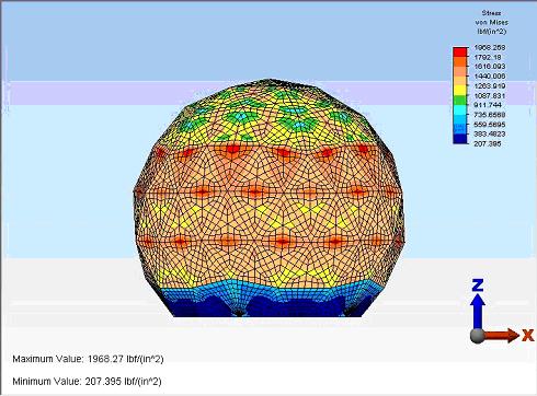
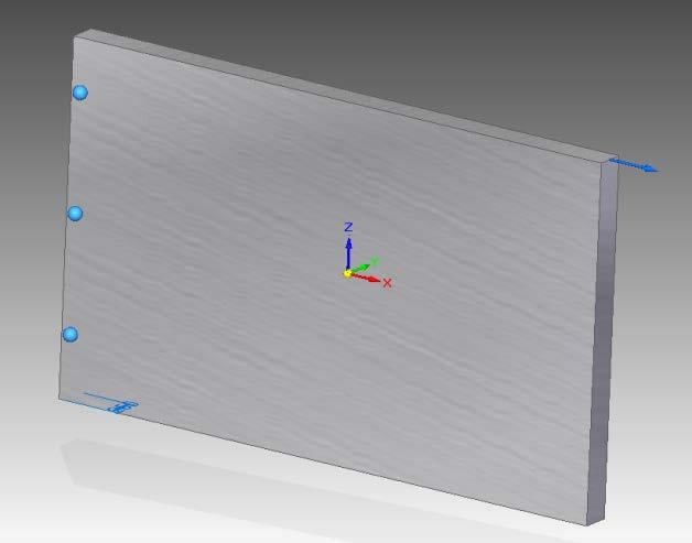
 Torque Load of 1000 in-lbf Inner Cylinder/Geometry Fully Constrained Initial Solve indicates Max Von Mises")
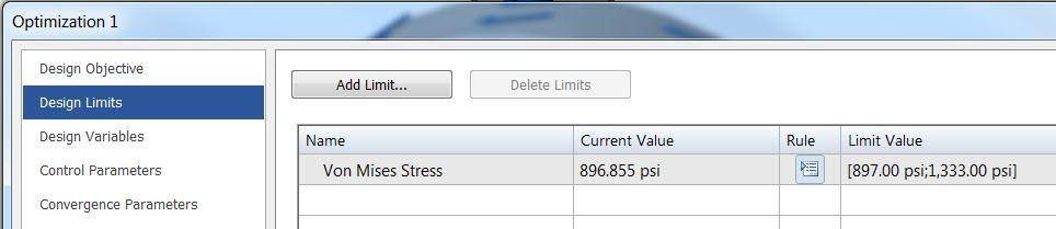
 Design Limit Von Mises Stress Less than 1333 psi (ie.")
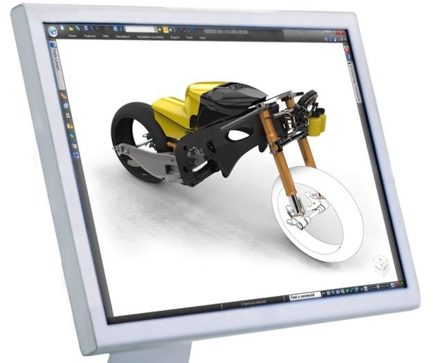
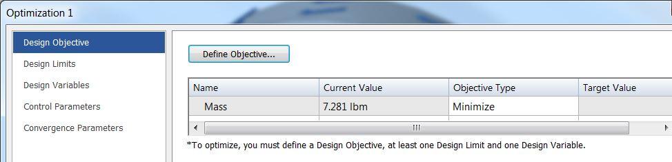
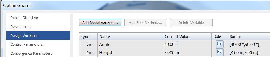
22 Design Optimization Example Idler Pulley Page 22 Idler Pulley with following inputs to optimization Material is Aluminum 1060 (Yield Stress of 4000 psi) Torque Load of 1000 in-lbf Inner Cylinder/Geometry Fully Constrained Initial Solve indicates Max Von Mises Stress of 897 psi Optimization Inputs Initial Solution of 897 psi for Max Von Mises Objective Minimize Mass (Initial Mass is lbm) Design Limit Von Mises Stress Less than 1333 psi (ie. FOS of 3) Design Variables using Angle and Height Dimensions Max Iterations - 20
23 Design Optimization Example Continued UI Inputs Page 23


24 Design Optimization Example Final Solution Final Solution after 10 iterations Minimized Mass to lbm ( reduction of lbm from model) Max Von Mises Stress of 1285 psi (below 1333 psi ) with FOS of 3 Original angle dimension of 40 degrees now degrees Original Height of cutout of 3 in now 3.9 in Page 24


25 Frequency Response Response of structure vs frequency Load is function of frequency Examples: Washing Machine Generator in Power Plant Automobile Tire out of balance Page 25


26 Transient Response Response of structure is function of time. Load changes vs time Examples: Vehicle on road with potholes Building subjected to earthquake Impact loading; drop testing Rocket wind and thrust load Page 26


27 Nonlinear Transient Response Loading and structural response a function of time Large displacement effects considered Material nonlinear effects considered Implicit and Explicit Solvers Examples: Impact/crash where material stress exceeds yield Model from - National Crash Analysis Center Page 27


28 Solution from Siemens Page 28 Daily work SOLID EDGE SIMULATION Linear Static Normal Modes Heat Transfer Geometric Nonlinear Advanced Modeling & Analysis Dynamic Response Nonlinear Design Optimization Flow-Thermal Femap with NX Nastran Analysis expertise
29 Advanced Modeling Beam Like structures modeled as two node beam elements Thin structures (1 to 10) modeled as shells Rigid components modeled as Lumped Masses Model Size now smaller, Advanced Analyses now possible Page 29

30 Advanced Modeling Mid-Surface Extraction Model thin-shell structures with plate elements Reduces FEA model size significantly Quickly change thickness value to optimize design Page 30


31 Solid Edge Simulation Automatic Finite Element Model Creation Shell & Solid tetrahedral elements Local mesh size control Based on Femap meshing technology Full Boundary Condition Support Geometry based constraints & loads Handles help define direction and orientation Quick Bar input options Powerful Analysis Capability Industry standard solver - NX Nastran Statics, normal modes and buckling analysis Automatic element quality checks Comprehensive Post Processing Fringe, color plots and contours Displacement, animation and mode shapes Report generation Page 31 Synchronous Technology with model associativity Remove unnecessary features Change geometry shape quickly & easily Mesh automatic update


32 Customer Success GEA Farm Technologies FEA allows us to save money during the design process, and save iterations at the prototype step. We can reduce four to five physical prototypes down to just one, shaving the design cycle by months. Alexander Laprise Engineer GEA Farm Technologies Page 32


33 Customer Success Zumex The use of FEA has become a great time-saving device. During physical machine testing, the breakages that occur coincide exactly as predicted by the FEA analysis. Eloy Herrero Marketing Manager Zumex Page 33

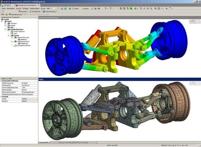
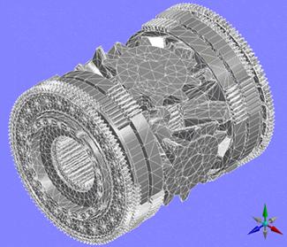
34 Example An electric drive system Objective : Verify the bracket s strength so that the maximum deformation is within the design criteria. Design the better products reducing vibration level during operation, so that the noise level can be kept lower than the competitors eventually. Solution : Predict the maximum deformation of the bracket by applying linear statics analysis. Predict the product s dynamic characteristics by using the frequency response analysis. Page 34

35 CAD assembly of an electric drive system Bracket Motor Frame Page 35

36 Supporting structures Page 36

37 Connections defined between parts Glued connection Page 37

38 Connections defined between parts Glued connection Page 38

39 Constraints Fixed surfaces Page 39

40 Bearing load Page 40

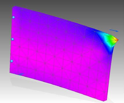
41 Mesh for FEA Page 41


42 Static analysis - Result Result < Criteria Ok! Page 42

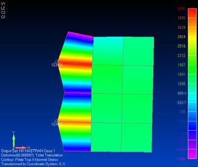
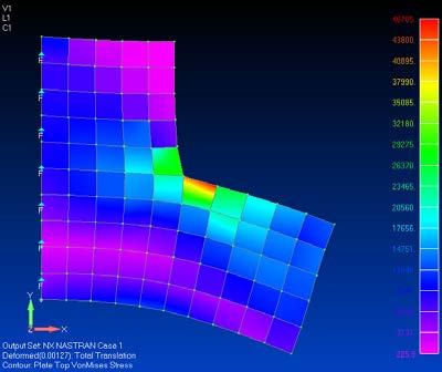
43 Linear Statics - Stresses To accurately recover stresses in shell and solid elements, the mesh must be very dense in areas of high stress gradients Stress Changing Too Fast Across One Element Page 43


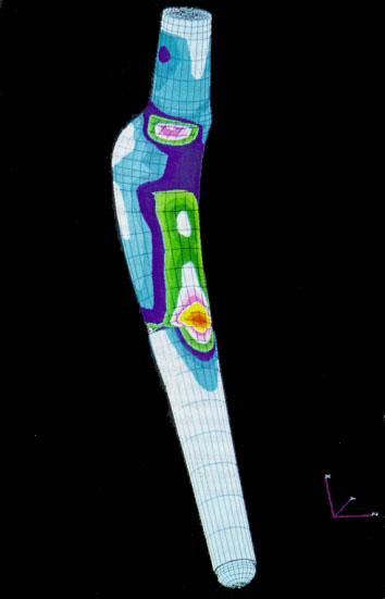
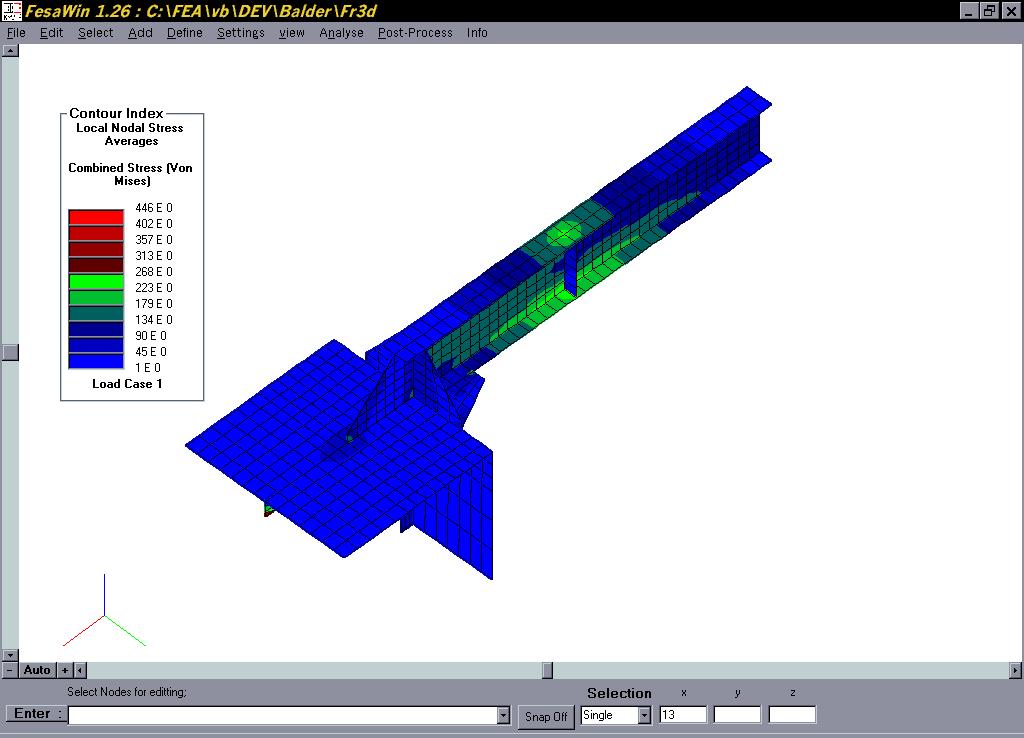
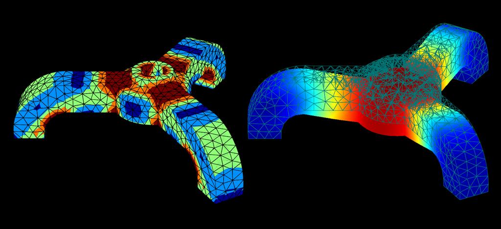
44 Stresses from the Web Page 44

45 Linear Statics - Stresses To accurately recover stresses in shell and solid elements, the mesh must be very dense in areas of high stress gradients Stress Changing Less Across an Element More Accurate Page 45

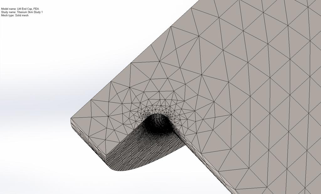
46 Linear Statics - Stresses Keeping Model Size Reasonable Increase the Mesh Density where you need it, decrease it where you don t Page 46
47 Linear Statics - Stresses Page 47
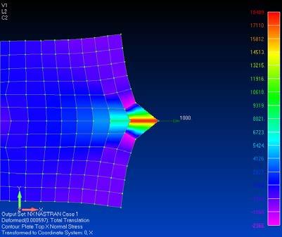
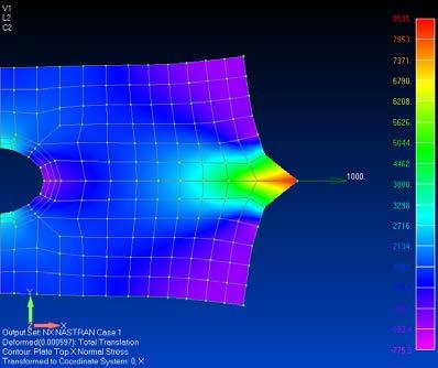
48 Guidelines for Good Stress Interpretation - Singularities Page 48

49 Guidelines for Linear Static Analysis - Stresses Remember the limitations of Linear analysis Increase Mesh Density in High Stress Regions Ignore Stress Answers at Singularities Zero Radius Fillets Inside Corners Loaded and Constrained Nodes Page 49

50 Normal Modes - Result No Mode Frequency Mode Shape Hz Hz Hz Page 50

51 Normal Modes No Mode Frequency Mode Shape Hz Hz Hz Page 51
52 Results summary Category Item to check Results GO/NG Strength Deformation Stress < Design criteria GO Normal modes Modal frequencies Excitation frequencies (3000 RPM = 50 Hz) GO Page 52
53 Considerations Source input = Rotating motor = 3000 RPM = 50 Hz Resonance frequencies to avoid = n*rpm = 50 Hz, 100 Hz, 150 Hz, 200 Hz,.. Need to carefully investigate the vibration level around Mode 1 and 5 as these are close to the above input frequencies. Mode 1 = 206 Hz Mode 5 = 505 Hz Vibration level? Response Analysis Page 53


54 Switch to the dedicated CAE software In Solid Edge, you can save your simulation model as the Femap file. Direct file translation including the results Open the file in the Femap for the further analysis Page 54

55 Frequency Response Excitation = Force = Motor mass x Gravity = 2 [kg] x 9.8 [mm^2/s] = 19.6 [N] Page 55
56 Frequency Response Page 56


57 Flow Analysis Fan Vent Air volume Page 57 Flow velocity

.")
58 Advanced Dynamics Examples Frequency response analysis is used to compute structural response to steady-state oscillatory excitation. Examples of oscillatory excitation include rotating machinery, unbalanced tires, and helicopter blades. In frequency response analysis the excitation is explicitly defined in the frequency domain. Excitations can be in the form of applied forces and enforced motions (displacements, velocities, or accelerations). Request responses between 50 and 80 Hz, every 0.05 Hz Page 58

59 Advanced Dynamics Examples Page 59
60 Two Takeaways Run Normal Modes on your Design to make sure everything is set up correctly, especially for assemblies Always be skeptical of a Stress Plot Page 60
Response Spectrum Analysis Shock and Seismic. FEMAP & NX Nastran
 Response Spectrum Analysis Shock and Seismic FEMAP & NX Nastran Table of Contents 1. INTRODUCTION... 3 2. THE ACCELEROGRAM... 4 3. CREATING A RESPONSE SPECTRUM... 5 4. NX NASTRAN METHOD... 8 5. RESPONSE
DISPENSA FEM in MSC. Nastran
 DISPENSA FEM in MSC. Nastran preprocessing: mesh generation material definitions definition of loads and boundary conditions solving: solving the (linear) set of equations components postprocessing: visualisation
PLEASURE VESSEL VIBRATION AND NOISE FINITE ELEMENT ANALYSIS
 PLEASURE VESSEL VIBRATION AND NOISE FINITE ELEMENT ANALYSIS 1 Macchiavello, Sergio *, 2 Tonelli, Angelo 1 D Appolonia S.p.A., Italy, 2 Rina Services S.p.A., Italy KEYWORDS pleasure vessel, vibration analysis,
Modal Analysis: What it is and is not Gerrit Visser
 Modal Analysis: What it is and is not Gerrit Visser What is a Modal Analysis? What answers do we get out of it? How is it useful? What does it not tell us? In this article, we ll discuss where a modal
3. Overview of MSC/NASTRAN
 3. Overview of MSC/NASTRAN MSC/NASTRAN is a general purpose finite element analysis program used in the field of static, dynamic, nonlinear, thermal, and optimization and is a FORTRAN program containing
Theoretical Manual Theoretical background to the Strand7 finite element analysis system
 Theoretical Manual Theoretical background to the Strand7 finite element analysis system Edition 1 January 2005 Strand7 Release 2.3 2004-2005 Strand7 Pty Limited All rights reserved Contents Preface Chapter
CAEFEM v9.5 Information
 CAEFEM v9.5 Information Concurrent Analysis Corporation, 50 Via Ricardo, Thousand Oaks, CA 91320 USA Tel. (805) 375 1060, Fax (805) 375 1061 email: info@caefem.com or support@caefem.com Web: http://www.caefem.com
Random Vibration Analysis in FEMAP An Introduction to the Hows and Whys
 Random Vibration Analysis in FEMAP An Introduction to the Hows and Whys Adrian Jensen, PE Senior Staff Mechanical Engineer Kyle Hamilton Staff Mechanical Engineer Table of Contents 1. INTRODUCTION... 4
8/1/2009. CAE 7962 Presentation
 CAE 7962 Presentation Gavin Patey Dameion Moores Aaron Henstridge Ashley Burke Brendan Harvey Fabio Faragalli Introduction Choosing mesh properties Explanation of the types of studies available and the
Noise Reduction of an Electrical Motor by Using a Numerical Model
 Noise Reduction of an Electrical Motor by Using a Numerical Model Ahmet Ali Uslu Arcelik A.S. R&D Department, Vibration & Acoustic Technologies Laboratory, Istanbul, Turkey. Summary Electrical motor is
D && 9.0 DYNAMIC ANALYSIS
 9.0 DYNAMIC ANALYSIS Introduction When a structure has a loading which varies with time, it is reasonable to assume its response will also vary with time. In such cases, a dynamic analysis may have to
ANSYS Explicit Dynamics Update. Mai Doan
 ANSYS Explicit Dynamics Update Mai Doan Mai.Doan@ansys.com +1 512 687 9523 1/32 ANSYS Explicit Dynamics Update Outline Introduction Solve Problems that were Difficult or Impossible in the Past Structural
FEM Validation. 12th January David Schmid Teamleader Structural Analysis
 FEM Validation 12th January 2012 David Schmid Teamleader Structural Analysis FEM Validation and Verification Each FE model which is used to substantiate flight material must be verified Depending on the
VIBRATION ANALYSIS OF AN AUTOMOTIVE SILENCER
 VIBRATION ANALYSIS OF AN AUTOMOTIVE SILENCER K. R. Gadre PG Student, Department Mechanical Engg., Sinhgad College of Engineering, Pune T. A. Jadhav Associate Professor, Department Mechanical Engg, Sinhgad
Stress Analysis and Validation of Superstructure of 15-meter Long Bus under Normal Operation
 AIJSTPME (2013) 6(3): 69-74 Stress Analysis and Validation of Superstructure of 15-meter Long Bus under Normal Operation Lapapong S., Pitaksapsin N., Sucharitpwatkul S.*, Tantanawat T., Naewngerndee R.
Dynamic Analysis in FEMAP. May 24 th, presented by Philippe Tremblay Marc Lafontaine
 Dynamic Analysis in FEMAP presented by Philippe Tremblay Marc Lafontaine marc.lafontaine@mayasim.com 514-951-3429 date May 24 th, 2016 Agenda NX Nastran Transient, frequency response, random, response
SECTION 1. Introduction to MD NASTRAN SOL 400
 SECTION 1 Introduction to MD NASTRAN SOL 400 S1-1 S1-2 What is "MD NASTRAN"? Evolution of engineering challenges: Complex systems vs. "just parts" Interacting environments Disparate tools and databases
Procedure for Performing Stress Analysis by Means of Finite Element Method (FEM)
") Procedure for Performing Stress Analysis by Means of Finite Element Method (FEM) Colaboração dos engºs Patrício e Ediberto da Petrobras 1. Objective This Technical Specification sets forth the minimum
Procedure for Performing Stress Analysis by Means of Finite Element Method (FEM) Colaboração dos engºs Patrício e Ediberto da Petrobras 1. Objective This Technical Specification sets forth the minimum
Finite Element Method
 Finite Element Method Finite Element Method (ENGC 6321) Syllabus Objectives Understand the basic theory of the FEM Know the behaviour and usage of each type of elements covered in this course one dimensional
Basics of Finite Element Analysis. Strength of Materials, Solid Mechanics
 Basics of Finite Element Analysis Strength of Materials, Solid Mechanics 1 Outline of Presentation Basic concepts in mathematics Analogies and applications Approximations to Actual Applications Improvisation
Leaf Spring (Material, Contact, geometric nonlinearity)
") 00 Summary Summary Nonlinear Static Analysis - Unit: N, mm - Geometric model: Leaf Spring.x_t Leaf Spring (Material, Contact, geometric nonlinearity) Nonlinear Material configuration - Stress - Strain
00 Summary Summary Nonlinear Static Analysis - Unit: N, mm - Geometric model: Leaf Spring.x_t Leaf Spring (Material, Contact, geometric nonlinearity) Nonlinear Material configuration - Stress - Strain
Recent developments for frequency domain analysis in LS-DYNA
 Recent developments for frequency domain analysis in LS-DYNA Yun Huang, Zhe Cui Livermore Software Technology Corporation 1 Introduction Since ls971 R6 version, a series of frequency domain features have
CIVL 8/7117 Chapter 12 - Structural Dynamics 1/75. To discuss the dynamics of a single-degree-of freedom springmass
 CIV 8/77 Chapter - /75 Introduction To discuss the dynamics of a single-degree-of freedom springmass system. To derive the finite element equations for the time-dependent stress analysis of the one-dimensional
Program System for Machine Dynamics. Abstract. Version 5.0 November 2017
 Program System for Machine Dynamics Abstract Version 5.0 November 2017 Ingenieur-Büro Klement Lerchenweg 2 D 65428 Rüsselsheim Phone +49/6142/55951 hd.klement@t-online.de What is MADYN? The program system
Modal and Static Structural Analysis of Exhaust Collector Box for Compressor test facility
 Modal and Static Structural Analysis of Exhaust Collector Box for Compressor test facility Shankar Gouda 1, Praveen M P 2 P G student, Department of Mechanical Engineering, EPCET, Bangalore, Karnataka,
Überblick von NX Nastran Multistep Nonlinear Solutions 401 und 402 Global Simcenter Portfolio Development Linz, 5.10.
 Überblick von NX Nastran Multistep Nonlinear Solutions 401 und 402 Martin.Kuessner@siemens.com Global Simcenter Portfolio Development Linz, 5.10.2018 Unrestricted Siemens AG 2018 Realize innovation. Simulation
ANALYSIS AND EXPERIMENT OF DYNAMIC CHARACTERISTICS OF ELECTRONIC DEVICE CHASSIS
 ANALYSIS AND EXPERIMENT OF DYNAMIC CHARACTERISTICS OF ELECTRONIC DEVICE CHASSIS HE QING, DU DONGMEI, JIANG XUCHAO Key Laboratory of Condition Monitoring and Control for Power Plant Equipment, Ministry
D : SOLID MECHANICS. Q. 1 Q. 9 carry one mark each.
 GTE 2016 Q. 1 Q. 9 carry one mark each. D : SOLID MECHNICS Q.1 single degree of freedom vibrating system has mass of 5 kg, stiffness of 500 N/m and damping coefficient of 100 N-s/m. To make the system
Size Effects In the Crushing of Honeycomb Structures
 45th AIAA/ASME/ASCE/AHS/ASC Structures, Structural Dynamics & Materials Conference 19-22 April 2004, Palm Springs, California AIAA 2004-1640 Size Effects In the Crushing of Honeycomb Structures Erik C.
Transient Thermal Flow and Thermal Stress Analysis Coupled NASTRAN and SC/Tetra
 Transient Thermal Flow and Thermal Stress Analysis Coupled NASTRAN and SC/Tetra Qin Yin Fan Software CRADLE Co., Ltd. ABSTRACT In SAE paper 2004-01-1345, author focused on how to use a steady state temperature
SHOCK RESPONSE SPECTRUM ANALYSIS VIA THE FINITE ELEMENT METHOD Revision C
 SHOCK RESPONSE SPECTRUM ANALYSIS VIA THE FINITE ELEMENT METHOD Revision C By Tom Irvine Email: tomirvine@aol.com November 19, 2010 Introduction This report gives a method for determining the response of
Structural Dynamics. Spring mass system. The spring force is given by and F(t) is the driving force. Start by applying Newton s second law (F=ma).
 is the driving force. Start by applying Newton s second law (F=ma).") Structural Dynamics Spring mass system. The spring force is given by and F(t) is the driving force. Start by applying Newton s second law (F=ma). We will now look at free vibrations. Considering the free
Structural Dynamics Spring mass system. The spring force is given by and F(t) is the driving force. Start by applying Newton s second law (F=ma). We will now look at free vibrations. Considering the free
Stresses Analysis of Petroleum Pipe Finite Element under Internal Pressure
 ISSN : 48-96, Vol. 6, Issue 8, ( Part -4 August 06, pp.3-38 RESEARCH ARTICLE Stresses Analysis of Petroleum Pipe Finite Element under Internal Pressure Dr.Ragbe.M.Abdusslam Eng. Khaled.S.Bagar ABSTRACT
Dynamic (Vibrational) and Static Structural Analysis of Ladder Frame
 and Static Structural Analysis of Ladder Frame") Dynamic (Vibrational) and Static Structural Analysis of Ladder Frame Ketan Gajanan Nalawade 1, Ashish Sabu 2, Baskar P 3 School of Mechanical and building science, VIT University, Vellore-632014, Tamil
Dynamic (Vibrational) and Static Structural Analysis of Ladder Frame Ketan Gajanan Nalawade 1, Ashish Sabu 2, Baskar P 3 School of Mechanical and building science, VIT University, Vellore-632014, Tamil
Creating Axisymmetric Models in FEMAP
 Creating Axisymmetric Models in FEMAP 1. Introduction NE/Nastran does not support 2-d axisymmetric elements. 3-d axisymmetric models are supported, and can be generated with a few additional steps. The
MSC Nastran N is for NonLinear as in SOL400. Shekhar Kanetkar, PhD
 MSC Nastran N is for NonLinear as in SOL400 Shekhar Kanetkar, PhD AGENDA What is SOL400? Types of Nonlinearities Contact Defining Contact Moving Rigid Bodies Friction in Contact S2S Contact CASI Solver
Computational Stiffness Method
 Computational Stiffness Method Hand calculations are central in the classical stiffness method. In that approach, the stiffness matrix is established column-by-column by setting the degrees of freedom
Efficient runner safety assessment during early design phase and root cause analysis
 IOP Conference Series: Earth and Environmental Science Efficient runner safety assessment during early design phase and root cause analysis To cite this article: Q W Liang et al 2012 IOP Conf. Ser.: Earth
Static and Dynamic Analysis of mm Steel Last Stage Blade for Steam Turbine
 Applied and Computational Mechanics 3 (2009) 133 140 Static and Dynamic Analysis of 1 220 mm Steel Last Stage Blade for Steam Turbine T. Míšek a,,z.kubín a aškoda POWER a. s., Tylova 57, 316 00 Plzeň,
Structural Analysis of Engine Cooling System for Passenger Car Vehicle
 Structural Analysis of Engine Cooling System for Passenger Car Vehicle ABSTRACT Gaikwad Vikrant C.*, Dr. Sawant Suresh M. **, Mr. K. Parmeshwar*** *Research Scholar, Department of Mechanical Engineering,
EDEM-Easy5/ADAMS Co-simulation of Particle-Structure Interaction Dr John Favier DEM Solutions Ltd
 EDEM-Easy5/ADAMS Co-simulation of Particle-Structure Interaction Dr John Favier DEM Solutions Ltd MSC.Software VPD Conference 2007 1 1 Outline DEM Solutions profile Why use Discrete Element Modelling (DEM)?
Introduction to Mechanical Vibration
 2103433 Introduction to Mechanical Vibration Nopdanai Ajavakom (NAV) 1 Course Topics Introduction to Vibration What is vibration? Basic concepts of vibration Modeling Linearization Single-Degree-of-Freedom
Thermal Analysis. with SolidWorks Simulation 2013 SDC. Paul M. Kurowski. Better Textbooks. Lower Prices.
 Thermal Analysis with SolidWorks Simulation 2013 Paul M. Kurowski SDC PUBLICATIONS Schroff Development Corporation Better Textbooks. Lower Prices. www.sdcpublications.com Visit the following websites to
4. Objectives of Research work
 4. Objectives of Research work 4.1 Objectives of Study: The design of bellows is challenging looking to varieties of applications and evaluation of stresses is further difficult to approximate due to its
Dynamic Stress Analysis of a Bus Systems
 Dynamic Stress Analysis of a Bus Systems *H. S. Kim, # Y. S. Hwang, # H. S. Yoon Commercial Vehicle Engineering & Research Center Hyundai Motor Company 772-1, Changduk, Namyang, Whasung, Kyunggi-Do, Korea
Effect of Mass Matrix Formulation Schemes on Dynamics of Structures
 Effect of Mass Matrix Formulation Schemes on Dynamics of Structures Swapan Kumar Nandi Tata Consultancy Services GEDC, 185 LR, Chennai 600086, India Sudeep Bosu Tata Consultancy Services GEDC, 185 LR,
Institute of Structural Engineering Page 1. Method of Finite Elements I. Chapter 2. The Direct Stiffness Method. Method of Finite Elements I
 Institute of Structural Engineering Page 1 Chapter 2 The Direct Stiffness Method Institute of Structural Engineering Page 2 Direct Stiffness Method (DSM) Computational method for structural analysis Matrix
Axisymmetric Modeling. This tutorial gives an overview of axisymmetric modeling. Learn how to:
 Axisymmetric Modeling I-DEAS Tutorials: Simulation Projects This tutorial gives an overview of axisymmetric modeling. Learn how to: sketch on the XZ plane apply boundary conditions mesh axisymmetric elements
Inventor 2019 lancering
 Inventor 2019 lancering Inventor Professional Factory Design Utility (Layout i AutoCAD og Inventor) Nesting Utility Navisworks 3ds Max Fusion 360 Vault Basic Nastran In-CAD HSM Ultimate Recap Pro Autodesk
Improving the Accuracy of Dynamic Vibration Fatigue Simulation
 Improving the Accuracy of Dynamic Vibration Fatigue Simulation Kurt Munson HBM Prenscia Agenda 2 1. Introduction 2. Dynamics and the frequency response function (FRF) 3. Using finite element analysis (FEA)
Chapter 5. Vibration Analysis. Workbench - Mechanical Introduction ANSYS, Inc. Proprietary 2009 ANSYS, Inc. All rights reserved.
 Workbench - Mechanical Introduction 12.0 Chapter 5 Vibration Analysis 5-1 Chapter Overview In this chapter, performing free vibration analyses in Simulation will be covered. In Simulation, performing a
Thermal Analysis with SOLIDWORKS Simulation 2015 and Flow Simulation 2015
 Thermal Analysis with SOLIDWORKS Simulation 2015 and Flow Simulation 2015 Paul M. Kurowski SDC PUBLICATIONS Better Textbooks. Lower Prices. www.sdcpublications.com Powered by TCPDF (www.tcpdf.org) Visit
Table of Contents. Preface...xvii. Part 1. Level
 Preface...xvii Part 1. Level 1... 1 Chapter 1. The Basics of Linear Elastic Behavior... 3 1.1. Cohesion forces... 4 1.2. The notion of stress... 6 1.2.1. Definition... 6 1.2.2. Graphical representation...
FEA A Guide to Good Practice. What to expect when you re expecting FEA A guide to good practice
 FEA A Guide to Good Practice What to expect when you re expecting FEA A guide to good practice 1. Background Finite Element Analysis (FEA) has transformed design procedures for engineers. Allowing more
Workshop 8. Lateral Buckling
 Workshop 8 Lateral Buckling cross section A transversely loaded member that is bent about its major axis may buckle sideways if its compression flange is not laterally supported. The reason buckling occurs
ME 475 Modal Analysis of a Tapered Beam
 ME 475 Modal Analysis of a Tapered Beam Objectives: 1. To find the natural frequencies and mode shapes of a tapered beam using FEA.. To compare the FE solution to analytical solutions of the vibratory
Aeroelastic Gust Response
 Aeroelastic Gust Response Civil Transport Aircraft - xxx Presented By: Fausto Gill Di Vincenzo 04-06-2012 What is Aeroelasticity? Aeroelasticity studies the effect of aerodynamic loads on flexible structures,
PStress R Pulley Stress Analysis Software Users Manual*
 PStress R Pulley Stress Analysis Software Users Manual* Issued: October 7, 2014 *For PStress V3.5 CONVEYOR DYNAMICS, INC. 1111 West Holly St. Bellingham, WA, 98225 (USA) Phone: +1 (360) 671-2200 Contents
Institute of Structural Engineering Page 1. Method of Finite Elements I. Chapter 2. The Direct Stiffness Method. Method of Finite Elements I
 Institute of Structural Engineering Page 1 Chapter 2 The Direct Stiffness Method Institute of Structural Engineering Page 2 Direct Stiffness Method (DSM) Computational method for structural analysis Matrix
Experimental and Numerical Modal Analysis of a Compressor Mounting Bracket
 IOSR Journal of Mechanical and Civil Engineering (IOSR-JMCE) e-issn: 2278-1684,p-ISSN: 2320-334X, Volume 14, Issue 1 Ver. VI (Jan. - Feb. 2017), PP 01-07 www.iosrjournals.org Experimental and Numerical
SIZE EFFECTS IN THE COMPRESSIVE CRUSHING OF HONEYCOMBS
 43rd AIAA/ASME/ASCE/AHS/ASC Structures, Structural Dynamics, and Materials Con 22-25 April 2002, Denver, Colorado SIZE EFFECTS IN THE COMPRESSIVE CRUSHING OF HONEYCOMBS Erik C. Mellquistand Anthony M.
Impact and Fracture Mechanics Assessment of a Fused Silica Window
 Arnold AFB Wind Tunnel Impact and Fracture Mechanics Analysis Rev-0 1 of 41 Impact and Fracture Mechanics Assessment of a Fused Silica Window Objective: Determine the survival probability of a fused silica
Finite element analysis of rotating structures
 Finite element analysis of rotating structures Dr. Louis Komzsik Chief Numerical Analyst Siemens PLM Software Why do rotor dynamics with FEM? Very complex structures with millions of degrees of freedom
Jonathan Fraser METEOR Project P07102 Environmental Test Stand Project Manager/Lead Engineer Detail Design Review Report
 Jonathan Fraser METEOR Project P07102 Environmental Test Stand Project Manager/Lead Engineer Detail Design Review Report The project, P07102 Environmental Test Stand, is specifically involved in the design,
Due Date 1 (for confirmation of final grade): Monday May 10 at 11:59pm Due Date 2 (absolute latest possible submission): Friday May 14 at 5pm
: Monday May 10 at 11:59pm Due Date 2 (absolute latest possible submission): Friday May 14 at 5pm") ! ME345 Modeling and Simulation, Spring 2010 Case Study 3 Assigned: Friday April 16! Due Date 1 (for email confirmation of final grade): Monday May 10 at 11:59pm Due Date 2 (absolute latest possible submission):
! ME345 Modeling and Simulation, Spring 2010 Case Study 3 Assigned: Friday April 16! Due Date 1 (for email confirmation of final grade): Monday May 10 at 11:59pm Due Date 2 (absolute latest possible submission):
COUPLED USE OF FEA AND EMA FOR THE INVESTIGATION OF DYNAMIC BEHAVIOUR OF AN INJECTION PUMP
 COUPLED USE OF FEA AND EMA FOR THE INVESTIGATION OF DYNAMIC BEHAVIOUR OF AN INJECTION PUMP Yasar Deger Wolfram Lienau Peter Sandford Sulzer Markets & Sulzer Pumps Ltd Sulzer Pumps (UK) Ltd Technology Ltd
Cable Tension APPENDIX D. Objectives: Demonstrate the use of elastic-plastic material properties. Create an enforced displacement on the model.
 APPENDIX D Cable Tension Objectives: Demonstrate the use of elastic-plastic material properties. Create an enforced displacement on the model. Run an MSC.Nastran nonlinear static analysis. Create an accurate
Completeness-Compatibility and Reviews for Finite Element Analysis Results
 Completeness-Compatibility and Reviews for Finite Element Analysis Results Prof. Venkatesh K*, Prof. Dr.Prakash S V**, Prof. Srinivasa Murthy P L** *(Department of Mechanical Engineering, SVERI s College
SOP Release. FEV Chassis Reliable Partner in Chassis Development. FEV Chassis Applications and Activities. Concept Layout. Design
 CHASSIS Reliable Partner in Chassis Development FEV Chassis Applications and Activities Founded in 1978, FEV is an internationally recognized leader in the design and development of internal combustion
NX Nastran 10. Rotor Dynamics User s Guide
 NX Nastran 10 Rotor Dynamics User s Guide Proprietary & Restricted Rights Notice 2014 Siemens Product Lifecycle Management Software Inc. All Rights Reserved. This software and related documentation are
COSMOS. Understanding Nonlinear Analysis. SolidWorks Corporation. Differences between linear and nonlinear analysis 2
 WHITE PAPER Understanding Nonlinear Analysis CONTENTS Differences between linear and nonlinear analysis 2 Understanding different types of nonlinear behavior 3-10 Nonlinear analysis can help you build
The Customer Driven Development of SIMPACK s Durability Interface
 The Customer Driven Development of SIMPACK s 5th SIMPACK User Meeting 2003 Stefan Dietz Content Problem Current Solutions in Comparison The Solution Implemented in SIMPACK Summary and Conclusion To Do
MECHANICAL FAILURE OF A COMPOSITE HELICOPTER STRUCTURE UNDER STATIC LOADING
 MECHANICAL FAILURE OF A COMPOSITE HELICOPTER STRUCTURE UNDER STATIC LOADING Steven Roy, Larry Lessard Dept. of Mechanical Engineering, McGill University, Montreal, Québec, Canada ABSTRACT The design and
LINEAR AND NONLINEAR BUCKLING ANALYSIS OF STIFFENED CYLINDRICAL SUBMARINE HULL
 LINEAR AND NONLINEAR BUCKLING ANALYSIS OF STIFFENED CYLINDRICAL SUBMARINE HULL SREELATHA P.R * M.Tech. Student, Computer Aided Structural Engineering, M A College of Engineering, Kothamangalam 686 666,
Tuesday, February 11, Chapter 3. Load and Stress Analysis. Dr. Mohammad Suliman Abuhaiba, PE
 1 Chapter 3 Load and Stress Analysis 2 Chapter Outline Equilibrium & Free-Body Diagrams Shear Force and Bending Moments in Beams Singularity Functions Stress Cartesian Stress Components Mohr s Circle for
Thermal Stress Analysis of a Bi- Metallic Plate
 WORKSHOP 10 Thermal Stress Analysis of a Bi- Metallic Plate MSC.Nastran 104 Exercise Workbook 10-1 10-2 MSC.Nastran 104 Exercise Workbook WORKSHOP 10 Thermal Stress Analysis of a Bi-Metallic Plate Model
Using Thermal Boundary Conditions in SOLIDWORKS Simulation to Simulate a Press Fit Connection
 Using Thermal Boundary Conditions in SOLIDWORKS Simulation to Simulate a Press Fit Connection Simulating a press fit condition in SOLIDWORKS Simulation can be very challenging when there is a large amount
Two Tier projects for students in ME 160 class
 ME 160 Introduction to Finite Element Method Spring 2016 Topics for Term Projects by Teams of 2 Students Instructor: Tai Ran Hsu, Professor, Dept. of Mechanical engineering, San Jose State University,
Finite Element Modules for Demonstrating Critical Concepts in Engineering Vibration Course
 Finite Element Modules for Demonstrating Critical Concepts in Engineering Vibration Course Shengyong Zhang Assistant Professor of Mechanical Engineering College of Engineering and Technology Purdue University
JEPPIAAR ENGINEERING COLLEGE
 JEPPIAAR ENGINEERING COLLEGE Jeppiaar Nagar, Rajiv Gandhi Salai 600 119 DEPARTMENT OFMECHANICAL ENGINEERING QUESTION BANK VI SEMESTER ME6603 FINITE ELEMENT ANALYSIS Regulation 013 SUBJECT YEAR /SEM: III
Vibration Analysis. with SOLIDWORKS Simulation 2018 SDC. Paul M. Kurowski. Better Textbooks. Lower Prices.
 Vibration Analysis with SOLIDWORKS Simulation 2018 Paul M. Kurowski SDC PUBLICATIONS Better Textbooks. Lower Prices. www.sdcpublications.com Powered by TCPDF (www.tcpdf.org) Visit the following websites
Homework Assignment 4 Root Finding Algorithms The Maximum Velocity of a Car Due: Friday, February 19, 2010 at 12noon
 ME 2016 A Spring Semester 2010 Computing Techniques 3-0-3 Homework Assignment 4 Root Finding Algorithms The Maximum Velocity of a Car Due: Friday, February 19, 2010 at 12noon Description and Outcomes In
DETC98/PTG-5788 VIBRO-ACOUSTIC STUDIES OF TRANSMISSION CASING STRUCTURES
 Proceedings of DETC98: 1998 ASME Design Engineering Technical Conference September 13-16, 1998, Atlanta, GA DETC98/PTG-5788 VIBRO-ACOUSTIC STUDIES O TRANSMISSION CASING STRUCTURES D. Crimaldi Graduate
Integration simulation method concerning speed control of ultrasonic motor
 Integration simulation method concerning speed control of ultrasonic motor R Miyauchi 1, B Yue 2, N Matsunaga 1 and S Ishizuka 1 1 Cybernet Systems Co., Ltd. 3 Kanda-neribeicho,Chiyoda-ku, Tokyo,101-0022,Japan
NONLINEAR STATIC AND MULTI-AXIAL FATIGUE ANALYSIS OF AUTOMOTIVE LOWER CONTROL ARM USING NEiNASTRAN
 NONLINEAR STATIC AND MULTI-AXIAL FATIGUE ANALYSIS OF AUTOMOTIVE LOWER CONTROL ARM USING NEiNASTRAN Dr. J.M. Mahishi, Director Engineering MS&M Engineering Inc, Farmington Hills, MI, USA SUMMARY The Lower
Comparative study between random vibration and linear static analysis using Miles method for thruster brackets in space structures
 Comparative study between random vibration and linear static analysis using Miles method for thruster brackets in space structures Ion DIMA*,1, Cristian-Gheorghe MOISEI 1, Calin-Dumitru COMAN 1, Mihaela
The Finite Element Method for Mechonics of Solids with ANSYS Applicotions
 The Finite Element Method for Mechonics of Solids with ANSYS Applicotions ELLIS H. DILL 0~~F~~~~"P Boca Raton London New Vork CRC Press is an imprint 01 the Taylor & Francis Group, an Informa business
MASS LOADING EFFECTS FOR HEAVY EQUIPMENT AND PAYLOADS Revision F
 MASS LOADING EFFECTS FOR HEAVY EQUIPMENT AND PAYLOADS Revision F By Tom Irvine Email: tomirvine@aol.com May 19, 2011 Introduction Consider a launch vehicle with a payload. Intuitively, a realistic payload
DEVELOPMENT OF ACTIVELY TUNED VIBRATION ABSORBER FOR WASHING MACHINE
 DEVELOPMENT OF ACTIVELY TUNED VIBRATION ABSORBER FOR WASHING MACHINE Mr.G.M.ABHISHEK 1, Mr. K. S. MANOBALA 2 1M.E.product design and commerce, psg college of technology, Coimbatore, Tamilnadu, India 2Assistant
Static & Dynamic. Analysis of Structures. Edward L.Wilson. University of California, Berkeley. Fourth Edition. Professor Emeritus of Civil Engineering
 Static & Dynamic Analysis of Structures A Physical Approach With Emphasis on Earthquake Engineering Edward LWilson Professor Emeritus of Civil Engineering University of California, Berkeley Fourth Edition
INTRODUCCION AL ANALISIS DE ELEMENTO FINITO (CAE / FEA)
") INTRODUCCION AL ANALISIS DE ELEMENTO FINITO (CAE / FEA) Title 3 Column (full page) 2 Column What is Finite Element Analysis? 1 Column Half page The Finite Element Method The Finite Element Method (FEM)
INTRODUCCION AL ANALISIS DE ELEMENTO FINITO (CAE / FEA) Title 3 Column (full page) 2 Column What is Finite Element Analysis? 1 Column Half page The Finite Element Method The Finite Element Method (FEM)
Module 10: Free Vibration of an Undampened 1D Cantilever Beam
 Module 10: Free Vibration of an Undampened 1D Cantilever Beam Table of Contents Page Number Problem Description Theory Geometry 4 Preprocessor 6 Element Type 6 Real Constants and Material Properties 7
Dynamic analysis of a reinforced concrete shear wall with strain rate effect. Synopsis. Introduction
 Dynamic analysis of a reinforced concrete shear wall with strain rate effect Synopsis A simplified analysis method for a reinforced concrete shear wall structure considering strain rate effects is presented.
Rotor-dynamics Analysis Process
 2001-36 Rotor-dynamics Analysis Process Mohammad A. Heidari, Ph.D. David L. Carlson Ted Yantis Technical Fellow Principal Engineer Principal Engineer The Boeing Company The Boeing Company The Boeing Company
Vibrationdata FEA Matlab GUI Package User Guide Revision A
 Vibrationdata FEA Matlab GUI Package User Guide Revision A By Tom Irvine Email: tom@vibrationdata.com March 25, 2014 Introduction Matlab Script: vibrationdata_fea_preprocessor.zip vibrationdata_fea_preprocessor.m
AE3610 Experiments in Fluid and Solid Mechanics TRANSIENT MEASUREMENTS OF HOOP STRESSES FOR A THIN-WALL PRESSURE VESSEL
 Objective AE3610 Experiments in Fluid and Solid Mechanics TRANSIENT MEASUREMENTS OF OOP STRESSES FOR A TIN-WA PRESSURE VESSE This experiment will allow you to investigate hoop and axial stress/strain relations
Improving the Ability to Simulate Noise from Brake Squeal
 SIMULATE MORE ACCURATELY Improving the Ability to Simulate Noise from Brake Squeal Multidiscipline Simulation playing a key role in reducing brake squeal noise and vibration Brake Squeal Analysis Background
Finite Element Modelling with Plastic Hinges
 01/02/2016 Marco Donà Finite Element Modelling with Plastic Hinges 1 Plastic hinge approach A plastic hinge represents a concentrated post-yield behaviour in one or more degrees of freedom. Hinges only
Q. 1 Q. 5 carry one mark each.
 General ptitude G Set-8 Q. 1 Q. 5 carry one mark each. Q.1 The chairman requested the aggrieved shareholders to him. () bare with () bore with (C) bear with (D) bare Q.2 Identify the correct spelling out
Spacecraft Structures
 Tom Sarafin Instar Engineering and Consulting, Inc. 6901 S. Pierce St., Suite 384, Littleton, CO 80128 303-973-2316 tom.sarafin@instarengineering.com Functions Being Compatible with the Launch Vehicle