PIPE FLOW. The Energy Equation. The first law of thermodynamics for a system is, in words = +
|
|
|
- Hilary Stokes
- 6 years ago
- Views:
Transcription
1 The Energy Equation PIPE FLOW The first law of thermodynamics for a system is, in words Time rate of increase of the total storage energy of the t Net time rate of energy addition by heat transfer into the system = + Net time rate of energy addition by work transfer into the system We could express this relation by using Bernoulli equation as : P out ρ g Vout + g + z out = P in ρg Vin + g + z in + h loss h loss head loss 1

2 EXAMPLE 1 Figure 1 A 30m wide river with a flowrate of 800m3/s flows over a rock pile as shown in Figure 1. Determine the direction of flow and the head loss associated with the flow across the rock pile.

3 EXAMPLE Figure An incompressible liquid flows steadily along the pipe shown in Figure. Determine the direction of flow and the head loss over the 6m length of pipe. 3
4 EXAMPLE 3 Figure 3 Water is pumped steadily through a 0.10m diameter pipe from one closed, pressurized tank to another as shown in Figure 3. The pump adds 4.0kW to the water and the head loss of the flow is 10m. Determine the velocity of the water leaving the pipe. 4
5 EXAMPLE 4 Figure 4 Water flows through a vertical pipe as shown in Figure 4. Is the flow up or down? Explain. 5
6 PIPE FLOW General Characteristic of Pipe Flow Figure 1 Some of the basic components of a typical pipe system are shown in Figure 1. They include the pipes, the various fitting used to connect the individual pipes to form the desired system, the flowrate control device or valves, and the pumps or turbines that add energy to or remove energy from the fluid. 1
7 (a) Pipe flow (b) Open-channel flow Figure The difference between open-channel flow and the pipe flow is in the fundamental mechanism that drives the flow. For open-channel flow, gravity alone is the driving force the water flows down a hill. For pipe flow, gravity may be important (the pipe need not be horizontal), but the main driving force is likely to be a pressure gradient along the pipe. If the pipe is not full, it is not possible to maintain this pressure difference, P 1 - P.
8 Laminar and Turbulent Flow Figure 3 The flow of a fluid in a pipe may be laminar flow or it may be turbulent flow. Osborne Reynolds ( ), a British scientist and mathematician, was the first to distinguish the difference between these two classifications of flow by experimental. For small enough flowrates the dye streak ( a streakline) will remain as a well-defined line as it flows along, with only slight blurring due to molecular diffusion of the dye into the surrounding water. It is called laminar flow. 3
9 For intermediate flowrate the dye streak fluctuates in time and space, and intermittent burst of irregular behavior appear along the streak. It is called transitional flow. For large enough flowrates the dye streak almost immediately becomes blurred and spreads across the entire pipe in a random fashion. It is called turbulent flow. To determine the flow conditions, one dimensionless parameter was introduced by Osborne Reynolds, called the Reynolds number, Re. Reynolds number, Re is the ratio of the inertia to viscous effects in the flow. It is written as ; ρvd Re = µ ρ : Density (kg/m 3 ) V : Average velocity in pipe (m/s) D : Diameter of pipe (m) µ : Dynamic viscosity (Ns/m ) The distinction between laminar and turbulent pipe flow and its dependence on an appropriate dimensionless quantity was first appointed out by Osborne Reynolds in
10 The Reynolds number ranges for which laminar, transitional or turbulent pipe flows are obtained cannot be precisely given. The actual transition from laminar to turbulent flow may take place at various Reynolds numbers, depending on how much the flow is disturbed by vibration of pipe, roughness of the entrance region and other factors. For general engineering purpose, the following values are appropriate : 1. The flow in a round pipe is laminar if the Reynolds number is less than approximately The flow in a round pipe is turbulent if the Reynolds numbers is greater that approximately For Reynolds number between these two limits, the flow may switch between laminar and turbulent conditions in an apparently random fashion. 5
11 Entrance Region and Fully Developed Laminar Flow Figure 4 The region of flow near where the fluid enters the pipe is termed the entrance region. The shape of velocity profile in the pipe depends on whether the flow is laminar or turbulent, as does the length of the entrance region, l e 6
12 The dimensionless entrance length, l e D, correlates quite well with the Reynolds number. Typical entrance lengths are given by ; l e D = 0.06(Re) (for laminar flow) and l e D 1 = 4.4( Re)6 (for turbulent flow) for Re=000, l e = 10 D for 10 4 <Re<10 5, 0 D < l e < 30 D From figure 4, the flow between () and (3) is termed fully developed flow. 7
13 Fully Developed Turbulent Flow Figure 5 Turbulent in pipe flow is actually more likely to occur than laminar flow in practical situation. Turbulent flow is a very complex process. 8
14 For pipe flow the value of the Reynolds number must be greater than approximately 4000 for turbulent flow. For flow along a flat plate the transition between laminar and turbulent flow occurs at a Reynolds number of approximately 500,000. Re flat plate = ρvl µ 9
15 PIPE FLOW Losses in Pipe It is often necessary to determine the head loss, h L, that occur in a pipe flow so that the energy equation, can be used in the analysis of pipe flow problems. The overall head loss for the pipe system consists of the head loss due to viscous effects in the straight pipes, termed the major loss and denoted h L-major. The head loss in various pipe components, termed the minor loss and denoted h L-minor. That is ; h L = h L-major + h L-minor The head loss designations of major and minor do not necessarily reflect the relative importance of each type of loss. For a pipe system that contains many components and a relatively short length of pipe, the minor loss may actually be larger than the major loss. 1
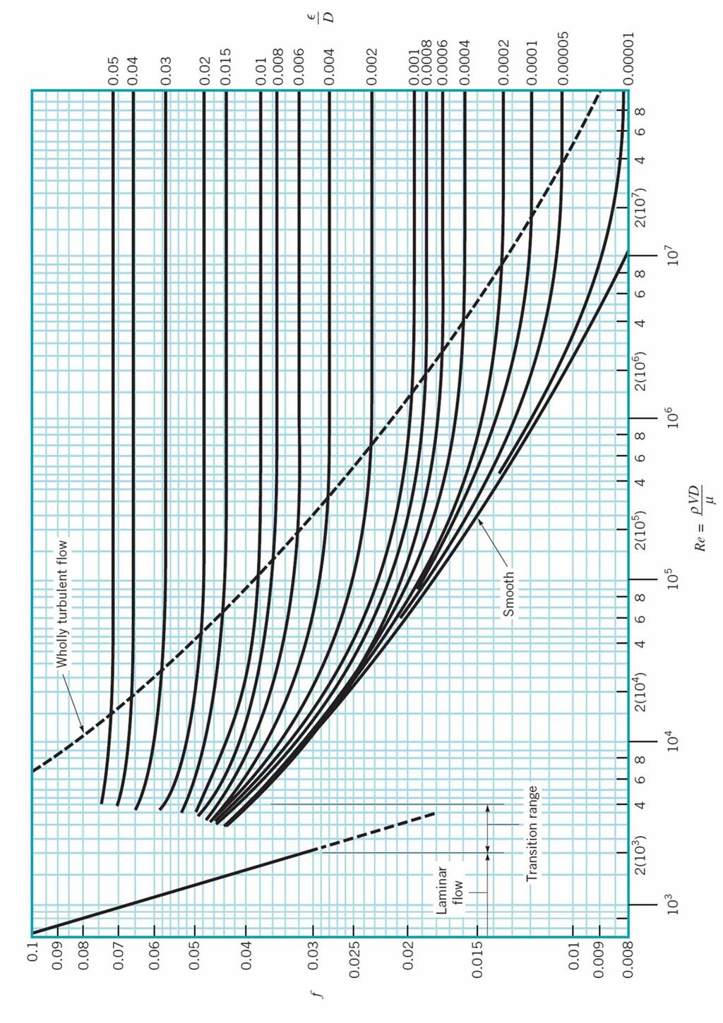
16 Major Losses The head loss, h L-major is given as ; = l V D g h L major f where f is friction factor. Above mention equation is called the Darcy-Weisbach equation. It is valid for any fully developed, steady, incompressible pipe flow, whether the pipe is horizontal or on hill Friction factor for laminar flow is ; 64 f = Re Friction factor for turbulent flow is based on Moody chart. It is because, in turbulent flow, Reynolds number and relative roughness influence the friction. ρvd Reynolds number, Re = µ ε Relative roughness = D (relative roughness is not present in the laminar flow)
17 3
18 The Moody chart is universally valid for all steady, fully developed, incompressible pipe flows. The following equation from Colebrook is valid for the entire non-laminar range of the Moody chart. It is called Colebrook formula. 1 f = ε.0log D Re f 4
19 Minor Losses The additional components such as valves and bend add to the overall head loss of the system, which is turn alters the losses associated with the flow through the valves. Minor losses termed as ; V hl minor = K L g where K L is the loss coefficient. Each geometry of pipe entrance has an associated loss coefficient. 5

20 Entrance flow conditions and loss coefficient. A 1 Condition: = 0 A or A A 1 = 6

21 Exit flow conditions and loss coefficient. A 1 Condition: = 0 A or A A 1 = 7
22 Losses also occur because of a change in pipe diameter For sudden contraction: K L A A 1 = = 1 = 1 A1 Ac C c 1 8
23 For sudden expansion K L A = A 1 1 9
24 EXAMPLE 1 Figure 1 Water flows from the nozzle attached to the spray tank shown in Figure 1. Determine the flowrate if the loss coefficient for the nozzle (based on upstream conditions) is 0.75 and the friction factor for the rough hose is

25 EXAMPLE Figure Water at 10 degree Celsius is pumped from a lake shown in Figure. If flowrate is 0.011m3/s, what is the maximum length inlet pipe, l, that can be used without cavitations occurring. 11

26 EXAMPLE 3 Figure 3 Water flows steadily through the.5cm diameter galvanized iron pipe system shown in Figure 3 at rate 6x10⁻⁴ m 3 /s. Your boss suggests that friction losses in the straight pipe sections are negligible compared to losses in the threaded elbows and fittings of the system. Do you agree or disagree with your boss? Support your answer with appropriate calculations. 1
27 13
28

29 PIPE FLOW A pipe system which has only one pipe line is called single pipe system. In many pipe systems there is more than one pipe line involved, and this mechanism is called multiple pipe systems. Multiple pipe systems are the same as for the single pipe system; however, because of the numerous unknowns involved, additional complexities may arise in solving for the flow in these systems. Single pipe system Multiple pipe systems 1

30 Series Pipe Systems Figure 1 One of the simplest multiple pipe systems is that containing pipes in series, as shown in Figure 1. Every fluid particle that passes through the system passes through each of the pipes. Thus, the flowrate (but not the velocity) is the same in each pipe, and the head loss from point A to point B is the sum of the head losses in each of the pipes. The governing equations can be written as follows ; Q = 1 = Q Q3 and h = h + h + h L( A B) L1 L L3

31 Parallel Pipe Systems Figure Another common multiple pipe system contains pipes in parallel, as shown in Figure. In this system a fluid particle traveling from A to B may take any of paths available, with the total flowrate equal to the sum of the flowrates in each pipe. The head loss experienced by any fluid particle traveling between these two locations is independent of the path taken. The governing equation for parallel pipe systems are ; Q = Q + Q + 1 Q3 and h = h = h L1 L L3 3
 equals the sum of the flowrates through pipes () and (3), or Q + 1 = Q Q3 The energy equation between the surfaces of each reservoir, the head loss for")
32 Loop Pipe Systems Figure 3 Another type of pipe system called a loop is shown in Figure 3. In this case, the flowrate through pipe (1) equals the sum of the flowrates through pipes () and (3), or Q + 1 = Q Q3 The energy equation between the surfaces of each reservoir, the head loss for pipe () must equal that for pipe (3), even though the pipe sizes and flowrates may be different for each. 4
33 For a fluid particle traveling through pipe (1) and (): 1 L L B B B A A A h h z g V g P z g V g P = + + ρ ρ For a fluid particle traveling through pipe (1) and (3): 3 1 L L B B B A A A h h z g V g P z g V g P = + + ρ ρ These can be combined to give : L3 L h h = 5

34 Three-reservoir system Figure 4 The branching system termed the three-reservoir problem shown in Figure 4. With all valves open, however, it is not necessarily obvious which direction the fluid flows. According to Figure 4, it is clear that fluid flows from reservoir A because the other reservoir levels are lower. 6
35 EXAMPLE 1 Air flows in a 0.5m diameter pipe at a rate of 10m 3 /s. The pipe diameter changes to 0.75m through a sudden expansion. Determine the pressure rise across this expansion. Explain how there can be a pressure rise across the expansion when there is an energy loss (K L > 0) EXAMPLE The surface elevations of reservoir A, B and C are at 640m, 545m and 580m respectively. A 0.45m diameter pipe, 3.km long runs from reservoir A to a node at an elevation of 610m, where the 0.3m diameter pipes each of 1.6km length branch from the original pipe and connect reservoirs B and C. If the friction factor for each pipe is 0.00, determine the flowrate in each pipe. 7

36 EXAMPLE 3 Figure 5 The three water-filled tanks shown in Figure 5 are connected by pipes as indicated. If minor losses are neglected, determine the flowrate in each pipe. 8
37 TUTORIAL 1 FOR PIPE FLOW Question 1 Carbon dioxide at 0ºC and a pressure of 550 kpa(abs) flows in a pipe at a rate of 0.04N/s. Determine the maximum diameter allowed if the flow is to be turbulent. Question A soft drink with the properties of 10ºC water is sucked through a 4mm diameter, 0.5m long straw at a rate of 4cm3/s. Is the flow at the outlet of the straw laminar? Is it fully developed? Explain. Question 3 Water flow in a constant diameter pipe with the following conditions measured: At section (a); P a =.5kPa and z a =17m. At section (b); P b =0kPa and z b =1m. Is the flow from (a) to (b) or from (b) to (a)? Explain. 1
38 PAST YEAR QUESTION FOR PIPE FLOW Question 1 Rajah 1 menunjukkan satu aliran dalam paip licin yang dikawal oleh tekanan udara di dalam tangki. Berapakah tekanan tolok (pressure gauge) P 1 yang diperlukan supaya air yang mempunyai ketumpatan dan kelikatan masing-masing ialah 998 kg/m3 dan 1.003x10⁻³ kg/m.s mengalir dengan kadar 60 m 3 /jam. Ambil pekali kehilangan pada pengecilan dan bengkokkan pada paip masing-masing 0.5 dan 0.4. Rajah 1 1
39 Question a) Terangkan apakah yang dimaksudkan dengan kehilangan besar (major loss) dan kehilangan kecil (minor loss) untuk suatu system paip. b) Sebuah system paip keluli komersil seperti yang dilakarkan dalam Rajah digunakan untuk mengepam bendalir penyejukkan yang berketumpatan bandingan 0.9 dan berkelikatan dinamik x10-4 Pa.s dari tangki B ke tangki A. Jika kadar aliran bendalir penyejukkan yang dipam ke tangki A ialah 140 liter per minit pada keadaan injap terbuka sepenuhnya, tentukan kuasa pam untuk memastikan aras cecair penyejukkan di dalam tangki A dan B kekal pada aras seperti yang dilakarkan dalam rajah. Semua dimensi dalam gambarajah adalah dalam unit meter (m). Rajah
40 Question 3 a) Explain the physical meaning of Reynolds number. b) Water is pumped at the rate of 60 liters per second from a reservoir to free discharge shown in Figure 3. All pipes are made of commercial steel. Determine the power required by the pump if the efficiency of the pump is 85%. Included all the losses in the pipe system. Moody diagram is given. Viscosity of water is given as 1x10⁻³ Pa.s. Figure 3 3
PIPE FLOW. General Characteristic of Pipe Flow. Some of the basic components of a typical pipe system are shown in Figure 1.
 PIPE FLOW General Characteristic of Pipe Flow Figure 1 Some of the basic components of a typical pipe system are shown in Figure 1. They include the pipes, the various fitting used to connect the individual
FLUID MECHANICS PROF. DR. METİN GÜNER COMPILER
 FLUID MECHANICS PROF. DR. METİN GÜNER COMPILER ANKARA UNIVERSITY FACULTY OF AGRICULTURE DEPARTMENT OF AGRICULTURAL MACHINERY AND TECHNOLOGIES ENGINEERING 1 5. FLOW IN PIPES Liquid or gas flow through pipes
Reynolds, an engineering professor in early 1880 demonstrated two different types of flow through an experiment:
 7 STEADY FLOW IN PIPES 7.1 Reynolds Number Reynolds, an engineering professor in early 1880 demonstrated two different types of flow through an experiment: Laminar flow Turbulent flow Reynolds apparatus
BERNOULLI EQUATION. The motion of a fluid is usually extremely complex.
 Chapter 5 Fluid in Motion The Bernoulli Equation BERNOULLI EQUATION The motion of a fluid is usually extremely complex. The study of a fluid at rest, or in relative equilibrium, was simplified by the absence
FLUID MECHANICS D203 SAE SOLUTIONS TUTORIAL 2 APPLICATIONS OF BERNOULLI SELF ASSESSMENT EXERCISE 1
 FLUID MECHANICS D203 SAE SOLUTIONS TUTORIAL 2 APPLICATIONS OF BERNOULLI SELF ASSESSMENT EXERCISE 1 1. A pipe 100 mm bore diameter carries oil of density 900 kg/m3 at a rate of 4 kg/s. The pipe reduces
When water (fluid) flows in a pipe, for example from point A to point B, pressure drop will occur due to the energy losses (major and minor losses).
 flows in a pipe, for example from point A to point B, pressure drop will occur due to the energy losses (major and minor losses).") PRESSURE DROP AND OSSES IN PIPE When water (luid) lows in a pipe, or example rom point A to point B, pressure drop will occur due to the energy losses (major and minor losses). A B Bernoulli equation:
PRESSURE DROP AND OSSES IN PIPE When water (luid) lows in a pipe, or example rom point A to point B, pressure drop will occur due to the energy losses (major and minor losses). A B Bernoulli equation:
Hydraulics. B.E. (Civil), Year/Part: II/II. Tutorial solutions: Pipe flow. Tutorial 1
, Year/Part: II/II. Tutorial solutions: Pipe flow. Tutorial 1") Hydraulics B.E. (Civil), Year/Part: II/II Tutorial solutions: Pipe flow Tutorial 1 -by Dr. K.N. Dulal Laminar flow 1. A pipe 200mm in diameter and 20km long conveys oil of density 900 kg/m 3 and viscosity
Hydraulics B.E. (Civil), Year/Part: II/II Tutorial solutions: Pipe flow Tutorial 1 -by Dr. K.N. Dulal Laminar flow 1. A pipe 200mm in diameter and 20km long conveys oil of density 900 kg/m 3 and viscosity
Mechanical Engineering Programme of Study
 Mechanical Engineering Programme of Study Fluid Mechanics Instructor: Marios M. Fyrillas Email: eng.fm@fit.ac.cy SOLVED EXAMPLES ON VISCOUS FLOW 1. Consider steady, laminar flow between two fixed parallel
IEK 108 PROCESS FLUID MECHANICS [MEKANIK BENDALIR PROSES]
![IEK 108 PROCESS FLUID MECHANICS [MEKANIK BENDALIR PROSES]](/thumbs/78/78048324.jpg "IEK 108 PROCESS FLUID MECHANICS [MEKANIK BENDALIR PROSES]") UNIVERSITI SAINS MALAYSIA Supplementary Semester Examination Academic Session 2010/2011 June 2011 IEK 108 PROCESS FLUID MECHANICS [MEKANIK BENDALIR PROSES] Duration: 3 hours Masa: [3 jam] Please check
UNIVERSITI SAINS MALAYSIA Supplementary Semester Examination Academic Session 2010/2011 June 2011 IEK 108 PROCESS FLUID MECHANICS [MEKANIK BENDALIR PROSES] Duration: 3 hours Masa: [3 jam] Please check
1-Reynold s Experiment
 Lect.No.8 2 nd Semester Flow Dynamics in Closed Conduit (Pipe Flow) 1 of 21 The flow in closed conduit ( flow in pipe ) is differ from this occur in open channel where the flow in pipe is at a pressure
Chapter 8: Flow in Pipes
 Objectives 1. Have a deeper understanding of laminar and turbulent flow in pipes and the analysis of fully developed flow 2. Calculate the major and minor losses associated with pipe flow in piping networks
FE Fluids Review March 23, 2012 Steve Burian (Civil & Environmental Engineering)
") Topic: Fluid Properties 1. If 6 m 3 of oil weighs 47 kn, calculate its specific weight, density, and specific gravity. 2. 10.0 L of an incompressible liquid exert a force of 20 N at the earth s surface.
Topic: Fluid Properties 1. If 6 m 3 of oil weighs 47 kn, calculate its specific weight, density, and specific gravity. 2. 10.0 L of an incompressible liquid exert a force of 20 N at the earth s surface.
CVE 372 HYDROMECHANICS EXERCISE PROBLEMS
 VE 37 HYDROMEHNIS EXERISE PROLEMS 1. pump that has the characteristic curve shown in the accompanying graph is to be installed in the system shown. What will be the discharge of water in the system? Take
Lesson 6 Review of fundamentals: Fluid flow
 Lesson 6 Review of fundamentals: Fluid flow The specific objective of this lesson is to conduct a brief review of the fundamentals of fluid flow and present: A general equation for conservation of mass
BUCKINGHAM PI THEOREM
 BUCKINGHAM PI THEOREM Dimensional Analysis It is used to determine the equation is right or wrong. The calculation is depends on the unit or dimensional conditions of the equations. For example; F=ma F=MLT
Hydraulics and hydrology
 Hydraulics and hydrology - project exercises - Class 4 and 5 Pipe flow Discharge (Q) (called also as the volume flow rate) is the volume of fluid that passes through an area per unit time. The discharge
Chapter (3) Water Flow in Pipes
 Water Flow in Pipes") Chapter (3) Water Flow in Pipes Water Flow in Pipes Bernoulli Equation Recall fluid mechanics course, the Bernoulli equation is: P 1 ρg + v 1 g + z 1 = P ρg + v g + z h P + h T + h L Here, we want to study
Chapter (3) Water Flow in Pipes Water Flow in Pipes Bernoulli Equation Recall fluid mechanics course, the Bernoulli equation is: P 1 ρg + v 1 g + z 1 = P ρg + v g + z h P + h T + h L Here, we want to study
FACULTY OF CHEMICAL & ENERGY ENGINEERING FLUID MECHANICS LABORATORY TITLE OF EXPERIMENT: MINOR LOSSES IN PIPE (E4)
") FACULTY OF CHEMICAL & ENERGY ENGINEERING FLUID MECHANICS LABORATORY TITLE OF EXPERIMENT: MINOR LOSSES IN PIPE (E4) 1 1.0 Objectives The objective of this experiment is to calculate loss coefficient (K
FACULTY OF CHEMICAL & ENERGY ENGINEERING FLUID MECHANICS LABORATORY TITLE OF EXPERIMENT: MINOR LOSSES IN PIPE (E4) 1 1.0 Objectives The objective of this experiment is to calculate loss coefficient (K
Lesson 37 Transmission Of Air In Air Conditioning Ducts
 Lesson 37 Transmission Of Air In Air Conditioning Ducts Version 1 ME, IIT Kharagpur 1 The specific objectives of this chapter are to: 1. Describe an Air Handling Unit (AHU) and its functions (Section 37.1).
Piping Systems and Flow Analysis (Chapter 3)
") Piping Systems and Flow Analysis (Chapter 3) 2 Learning Outcomes (Chapter 3) Losses in Piping Systems Major losses Minor losses Pipe Networks Pipes in series Pipes in parallel Manifolds and Distribution
Piping Systems and Flow Analysis (Chapter 3) 2 Learning Outcomes (Chapter 3) Losses in Piping Systems Major losses Minor losses Pipe Networks Pipes in series Pipes in parallel Manifolds and Distribution
Water Circuit Lab. The pressure drop along a straight pipe segment can be calculated using the following set of equations:
 Water Circuit Lab When a fluid flows in a conduit, there is friction between the flowing fluid and the pipe walls. The result of this friction is a net loss of energy in the flowing fluid. The fluid pressure
ME 305 Fluid Mechanics I. Part 8 Viscous Flow in Pipes and Ducts. Flow in Pipes and Ducts. Flow in Pipes and Ducts (cont d)
") ME 305 Fluid Mechanics I Flow in Pipes and Ducts Flow in closed conduits (circular pipes and non-circular ducts) are very common. Part 8 Viscous Flow in Pipes and Ducts These presentations are prepared
ME 305 Fluid Mechanics I Flow in Pipes and Ducts Flow in closed conduits (circular pipes and non-circular ducts) are very common. Part 8 Viscous Flow in Pipes and Ducts These presentations are prepared
DCC5143: FLUID MECHANICS
 SECTION A: 50 MARKS BAHAGIAN A: 50 MARKAH INSTRUCTION: This section consists of TWO (2) structured questions. Please answer ALL questions. ARAHAN: Bahagian ini mengandungi DUA (2) soalan berstruktur. Sila
Major and Minor Losses
 Abstract Major and Minor Losses Caitlyn Collazo, Team 2 (1:00 pm) A Technovate fluid circuit system was used to determine the pressure drop across a pipe section and across an orifice. These pressure drops
EXPERIMENT No.1 FLOW MEASUREMENT BY ORIFICEMETER
 EXPERIMENT No.1 FLOW MEASUREMENT BY ORIFICEMETER 1.1 AIM: To determine the co-efficient of discharge of the orifice meter 1.2 EQUIPMENTS REQUIRED: Orifice meter test rig, Stopwatch 1.3 PREPARATION 1.3.1
Viscous Flow in Ducts
 Dr. M. Siavashi Iran University of Science and Technology Spring 2014 Objectives 1. Have a deeper understanding of laminar and turbulent flow in pipes and the analysis of fully developed flow 2. Calculate
Chapter 6. Losses due to Fluid Friction
 Chapter 6 Losses due to Fluid Friction 1 Objectives ä To measure the pressure drop in the straight section of smooth, rough, and packed pipes as a function of flow rate. ä To correlate this in terms of
JJ309 : FLUID MECHANICS
 INSTRUCTION: This section consists of SIX (6) structured questions. Answer FOUR (4) questions only. ARAHAN: Bahagian ini mengandungi ENAM (6) soalan struktur. Jawab EMPAT (4) soalan sahaja. QUESTION 1
ME 305 Fluid Mechanics I. Chapter 8 Viscous Flow in Pipes and Ducts
 ME 305 Fluid Mechanics I Chapter 8 Viscous Flow in Pipes and Ducts These presentations are prepared by Dr. Cüneyt Sert Department of Mechanical Engineering Middle East Technical University Ankara, Turkey
2 Internal Fluid Flow
 Internal Fluid Flow.1 Definitions Fluid Dynamics The study of fluids in motion. Static Pressure The pressure at a given point exerted by the static head of the fluid present directly above that point.
Pipe Flow. Lecture 17
 Pipe Flow Lecture 7 Pipe Flow and the Energy Equation For pipe flow, the Bernoulli equation alone is not sufficient. Friction loss along the pipe, and momentum loss through diameter changes and corners
LECTURE 6- ENERGY LOSSES IN HYDRAULIC SYSTEMS SELF EVALUATION QUESTIONS AND ANSWERS
 LECTURE 6- ENERGY LOSSES IN HYDRAULIC SYSTEMS SELF EVALUATION QUESTIONS AND ANSWERS 1. What is the head loss ( in units of bars) across a 30mm wide open gate valve when oil ( SG=0.9) flow through at a
EAH 225 / JAH 331/3 - Hydraulics
 UNIVERSITI SAINS MALAYSIA 2 nd. Semester Examination Academic Session 2001/2002 FEBRUARY / MARCH 2002 EAH 225 / JAH 331/3 - Hydraulics Time : 3 hour Instruction to candidates:- 1. Ensure that this paper
FE Exam Fluids Review October 23, Important Concepts
 FE Exam Fluids Review October 3, 013 mportant Concepts Density, specific volume, specific weight, specific gravity (Water 1000 kg/m^3, Air 1. kg/m^3) Meaning & Symbols? Stress, Pressure, Viscosity; Meaning
Chapter 8: Flow in Pipes
 8-1 Introduction 8-2 Laminar and Turbulent Flows 8-3 The Entrance Region 8-4 Laminar Flow in Pipes 8-5 Turbulent Flow in Pipes 8-6 Fully Developed Pipe Flow 8-7 Minor Losses 8-8 Piping Networks and Pump
ACCOUNTING FOR FRICTION IN THE BERNOULLI EQUATION FOR FLOW THROUGH PIPES
 ACCOUNTING FOR FRICTION IN THE BERNOULLI EQUATION FOR FLOW THROUGH PIPES Some background information first: We have seen that a major limitation of the Bernoulli equation is that it does not account for
IEK 108 PROCESS FLUID MECHANICS [MEKANIK BENDALIR PROSES]
![IEK 108 PROCESS FLUID MECHANICS [MEKANIK BENDALIR PROSES]](/thumbs/71/66060892.jpg "IEK 108 PROCESS FLUID MECHANICS [MEKANIK BENDALIR PROSES]") UNIVERSITI SAINS MALAYSIA Second Semester Examination 2009/2010 Academic Session April/May 2010 IEK 108 PROCESS FLUID MECHANICS [MEKANIK BENDALIR PROSES] Duration: 3 hours Masa: [3 jam] Please check that
UNIVERSITI SAINS MALAYSIA Second Semester Examination 2009/2010 Academic Session April/May 2010 IEK 108 PROCESS FLUID MECHANICS [MEKANIK BENDALIR PROSES] Duration: 3 hours Masa: [3 jam] Please check that
S.E. (Mech.) (First Sem.) EXAMINATION, (Common to Mech/Sandwich) FLUID MECHANICS (2008 PATTERN) Time : Three Hours Maximum Marks : 100
 (First Sem.) EXAMINATION, (Common to Mech/Sandwich) FLUID MECHANICS (2008 PATTERN) Time : Three Hours Maximum Marks : 100") Total No. of Questions 12] [Total No. of Printed Pages 8 Seat No. [4262]-113 S.E. (Mech.) (First Sem.) EXAMINATION, 2012 (Common to Mech/Sandwich) FLUID MECHANICS (2008 PATTERN) Time : Three Hours Maximum
Total No. of Questions 12] [Total No. of Printed Pages 8 Seat No. [4262]-113 S.E. (Mech.) (First Sem.) EXAMINATION, 2012 (Common to Mech/Sandwich) FLUID MECHANICS (2008 PATTERN) Time : Three Hours Maximum
Chapter 6. Losses due to Fluid Friction
 Chapter 6 Losses due to Fluid Friction 1 Objectives To measure the pressure drop in the straight section of smooth, rough, and packed pipes as a function of flow rate. To correlate this in terms of the
Part A: 1 pts each, 10 pts total, no partial credit.
 Part A: 1 pts each, 10 pts total, no partial credit. 1) (Correct: 1 pt/ Wrong: -3 pts). The sum of static, dynamic, and hydrostatic pressures is constant when flow is steady, irrotational, incompressible,
Experiment (4): Flow measurement
: Flow measurement") Experiment (4): Flow measurement Introduction: The flow measuring apparatus is used to familiarize the students with typical methods of flow measurement of an incompressible fluid and, at the same time
Experiment (4): Flow measurement Introduction: The flow measuring apparatus is used to familiarize the students with typical methods of flow measurement of an incompressible fluid and, at the same time
Chapter (3) Water Flow in Pipes
 Water Flow in Pipes") Chapter (3) Water Flow in Pipes Water Flow in Pipes Bernoulli Equation Recall fluid mechanics course, the Bernoulli equation is: P 1 ρg + v 1 g + z 1 = P ρg + v g + z h P + h T + h L Here, we want to study
Chapter (3) Water Flow in Pipes Water Flow in Pipes Bernoulli Equation Recall fluid mechanics course, the Bernoulli equation is: P 1 ρg + v 1 g + z 1 = P ρg + v g + z h P + h T + h L Here, we want to study
Experiment- To determine the coefficient of impact for vanes. Experiment To determine the coefficient of discharge of an orifice meter.
 SUBJECT: FLUID MECHANICS VIVA QUESTIONS (M.E 4 th SEM) Experiment- To determine the coefficient of impact for vanes. Q1. Explain impulse momentum principal. Ans1. Momentum equation is based on Newton s
Chapter 10 Flow in Conduits
 Chapter 10 Flow in Conduits 10.1 Classifying Flow Laminar Flow and Turbulent Flow Laminar flow Unpredictable Turbulent flow Near entrance: undeveloped developing flow In developing flow, the wall shear
Review of pipe flow: Friction & Minor Losses
 ENVE 204 Lecture -1 Review of pipe flow: Friction & Minor Losses Assist. Prof. Neslihan SEMERCİ Marmara University Department of Environmental Engineering Important Definitions Pressure Pipe Flow: Refers
V/ t = 0 p/ t = 0 ρ/ t = 0. V/ s = 0 p/ s = 0 ρ/ s = 0
 UNIT III FLOW THROUGH PIPES 1. List the types of fluid flow. Steady and unsteady flow Uniform and non-uniform flow Laminar and Turbulent flow Compressible and incompressible flow Rotational and ir-rotational
CHARACTERISTIC OF FLUIDS. A fluid is defined as a substance that deforms continuously when acted on by a shearing stress at any magnitude.
 CHARACTERISTIC OF FLUIDS A fluid is defined as a substance that deforms continuously when acted on by a shearing stress at any magnitude. In a fluid at rest, normal stress is called pressure. 1 Dimensions,
AEROSPACE ENGINEERING DEPARTMENT. Second Year - Second Term ( ) Fluid Mechanics & Gas Dynamics
 Fluid Mechanics & Gas Dynamics") AEROSPACE ENGINEERING DEPARTMENT Second Year - Second Term (2008-2009) Fluid Mechanics & Gas Dynamics Similitude,Dimensional Analysis &Modeling (1) [7.2R*] Some common variables in fluid mechanics include:
AEROSPACE ENGINEERING DEPARTMENT Second Year - Second Term (2008-2009) Fluid Mechanics & Gas Dynamics Similitude,Dimensional Analysis &Modeling (1) [7.2R*] Some common variables in fluid mechanics include:
IEK 212 PROCESS HEAT TRANSFER [PEMINDAHAN HABA PROSES]
![IEK 212 PROCESS HEAT TRANSFER [PEMINDAHAN HABA PROSES]](/thumbs/83/88987964.jpg "IEK 212 PROCESS HEAT TRANSFER [PEMINDAHAN HABA PROSES]") UNIVERSITI SAINS MALAYSIA Supplementary Semester Examination Academic Session 2009/2010 June 2010 IEK 212 PROCESS HEAT TRANSFER [PEMINDAHAN HABA PROSES] Duration: 3 hours [Masa: 3 jam] Please check that
UNIVERSITI SAINS MALAYSIA Supplementary Semester Examination Academic Session 2009/2010 June 2010 IEK 212 PROCESS HEAT TRANSFER [PEMINDAHAN HABA PROSES] Duration: 3 hours [Masa: 3 jam] Please check that
UNIT I FLUID PROPERTIES AND STATICS
 SIDDHARTH GROUP OF INSTITUTIONS :: PUTTUR Siddharth Nagar, Narayanavanam Road 517583 QUESTION BANK (DESCRIPTIVE) Subject with Code : Fluid Mechanics (16CE106) Year & Sem: II-B.Tech & I-Sem Course & Branch:
COURSE NUMBER: ME 321 Fluid Mechanics I 3 credit hour. Basic Equations in fluid Dynamics
 COURSE NUMBER: ME 321 Fluid Mechanics I 3 credit hour Basic Equations in fluid Dynamics Course teacher Dr. M. Mahbubur Razzaque Professor Department of Mechanical Engineering BUET 1 Description of Fluid
Signature: (Note that unsigned exams will be given a score of zero.)
") Neatly print your name: Signature: (Note that unsigned exams will be given a score of zero.) Circle your lecture section (-1 point if not circled, or circled incorrectly): Prof. Dabiri Prof. Wassgren Prof.
Neatly print your name: Signature: (Note that unsigned exams will be given a score of zero.) Circle your lecture section (-1 point if not circled, or circled incorrectly): Prof. Dabiri Prof. Wassgren Prof.
Engineers Edge, LLC PDH & Professional Training
 510 N. Crosslane Rd. Monroe, Georgia 30656 (770) 266-6915 fax (678) 643-1758 Engineers Edge, LLC PDH & Professional Training Copyright, All Rights Reserved Engineers Edge, LLC Pipe Flow-Friction Factor
Q1 Give answers to all of the following questions (5 marks each):
:") FLUID MECHANICS First Year Exam Solutions 03 Q Give answers to all of the following questions (5 marks each): (a) A cylinder of m in diameter is made with material of relative density 0.5. It is moored
FLUID MECHANICS First Year Exam Solutions 03 Q Give answers to all of the following questions (5 marks each): (a) A cylinder of m in diameter is made with material of relative density 0.5. It is moored
Chapter (6) Energy Equation and Its Applications
 Energy Equation and Its Applications") Chapter (6) Energy Equation and Its Applications Bernoulli Equation Bernoulli equation is one of the most useful equations in fluid mechanics and hydraulics. And it s a statement of the principle of conservation
Chapter (6) Energy Equation and Its Applications Bernoulli Equation Bernoulli equation is one of the most useful equations in fluid mechanics and hydraulics. And it s a statement of the principle of conservation
Chapter Four fluid flow mass, energy, Bernoulli and momentum
 4-1Conservation of Mass Principle Consider a control volume of arbitrary shape, as shown in Fig (4-1). Figure (4-1): the differential control volume and differential control volume (Total mass entering
Lecture 2 Flow classifications and continuity
 Lecture 2 Flow classifications and continuity Dr Tim Gough: t.gough@bradford.ac.uk General information 1 No tutorial week 3 3 rd October 2013 this Thursday. Attempt tutorial based on examples from today
Chapter 7 FLOW THROUGH PIPES
 Chapter 7 FLOW THROUGH PIPES 7-1 Friction Losses of Head in Pipes 7-2 Secondary Losses of Head in Pipes 7-3 Flow through Pipe Systems 48 7-1 Friction Losses of Head in Pipes: There are many types of losses
ρg 998(9.81) LV 50 V. d2g 0.062(9.81)
 LV 50 V. d2g 0.062(9.81)") 6.78 In Fig. P6.78 the connecting pipe is commercial steel 6 cm in diameter. Estimate the flow rate, in m 3 /h, if the fluid is water at 0 C. Which way is the flow? Solution: For water, take ρ = 998 kg/m
6.78 In Fig. P6.78 the connecting pipe is commercial steel 6 cm in diameter. Estimate the flow rate, in m 3 /h, if the fluid is water at 0 C. Which way is the flow? Solution: For water, take ρ = 998 kg/m
EKC 511 Advanced Separation Process
 UNIVERSITI SAINS MALAYSIA First Semester Examination 2009/2010 Academic Session November 2009 EKC 511 Advanced Separation Process Duration : 3 hours Please check that this examination paper consists of
MYcsvtu Notes HEAT TRANSFER BY CONVECTION
 www.mycsvtunotes.in HEAT TRANSFER BY CONVECTION CONDUCTION Mechanism of heat transfer through a solid or fluid in the absence any fluid motion. CONVECTION Mechanism of heat transfer through a fluid in
FLOW IN PIPES. Mark J McCready University of Notre Dame July 24, chemeprof.com
 FLOW IN PIPES Mark J McCready University of Notre Dame July 24, 2017 OVERVIEW This lecture will provide the simplest framework to explain The three forces at that are important to fluid flow in pipes The
BASIC EQUATION. Rotational speed = = ABC 60
 CENTRIFUGAL PUMP BASIC EQUATION Rotational speed = =?@ = ABC 60 = = linear velocity in m/s? = radius in m @ = angular velocity in rad/s B = diameter in m C = rotation per minute Power OPQR? = S U = O V
BASIC EQUATION. Rotational speed. u = linear velocity in m/s r = radius in m ω = angular velocity in rad/s D = diameter in m N = rotation per minute
 CENTRIFUGAL PUMP BASIC EQUATION Rotational speed u = rω = πdn 60 u = linear velocity in m/s r = radius in m ω = angular velocity in rad/s D = diameter in m N = rotation per minute Power Power = F V = P
ME 309 Fluid Mechanics Fall 2010 Exam 2 1A. 1B.
 Fall 010 Exam 1A. 1B. Fall 010 Exam 1C. Water is flowing through a 180º bend. The inner and outer radii of the bend are 0.75 and 1.5 m, respectively. The velocity profile is approximated as C/r where C
STEADY FLOW THROUGH PIPES DARCY WEISBACH EQUATION FOR FLOW IN PIPES. HAZEN WILLIAM S FORMULA, LOSSES IN PIPELINES, HYDRAULIC GRADE LINES AND ENERGY
 STEADY FLOW THROUGH PIPES DARCY WEISBACH EQUATION FOR FLOW IN PIPES. HAZEN WILLIAM S FORMULA, LOSSES IN PIPELINES, HYDRAULIC GRADE LINES AND ENERGY LINES 1 SIGNIFICANCE OF CONDUITS In considering the convenience
Chapter 10: Flow Flow in in Conduits Conduits Dr Ali Jawarneh
 Chater 10: Flow in Conduits By Dr Ali Jawarneh Hashemite University 1 Outline In this chater we will: Analyse the shear stress distribution across a ie section. Discuss and analyse the case of laminar
An overview of the Hydraulics of Water Distribution Networks
 An overview of the Hydraulics of Water Distribution Networks June 21, 2017 by, P.E. Senior Water Resources Specialist, Santa Clara Valley Water District Adjunct Faculty, San José State University 1 Outline
Hydroelectric Design
 INTERAMERICAN UNIVERSITY OF BAYAMON PUERTO RICO Hydroelectric Design Dr. Eduardo G. Pérez Díaz Erik T. Rosado González 5/14/2012 Hydroelectric design project for fluid class. TABLE OF CONTENTS TABLE OF
2.The lines that are tangent to the velocity vectors throughout the flow field are called steady flow lines. True or False A. True B.
 CHAPTER 03 1. Write Newton's second law of motion. YOUR ANSWER: F = ma 2.The lines that are tangent to the velocity vectors throughout the flow field are called steady flow lines. True or False 3.Streamwise
EAH 221/3 Fluid Mechanics For Civil Engineers [Mekanik Bendalir Untuk Jurutera Awam]
![EAH 221/3 Fluid Mechanics For Civil Engineers [Mekanik Bendalir Untuk Jurutera Awam]](/thumbs/74/70689363.jpg "EAH 221/3 Fluid Mechanics For Civil Engineers [Mekanik Bendalir Untuk Jurutera Awam]") UNIVERSITI SAINS MALAYSIA First Semester Examination Academic Session 2009/2010 November 2009 EAH 221/3 Fluid Mechanics For Civil Engineers [Mekanik Bendalir Untuk Jurutera Awam] Duration : 3 hours [Masa
UNIVERSITI SAINS MALAYSIA First Semester Examination Academic Session 2009/2010 November 2009 EAH 221/3 Fluid Mechanics For Civil Engineers [Mekanik Bendalir Untuk Jurutera Awam] Duration : 3 hours [Masa
MASS, MOMENTUM, AND ENERGY EQUATIONS
 MASS, MOMENTUM, AND ENERGY EQUATIONS This chapter deals with four equations commonly used in fluid mechanics: the mass, Bernoulli, Momentum and energy equations. The mass equation is an expression of the
HEAT TRANSFER BY CONVECTION. Dr. Şaziye Balku 1
 HEAT TRANSFER BY CONVECTION Dr. Şaziye Balku 1 CONDUCTION Mechanism of heat transfer through a solid or fluid in the absence any fluid motion. CONVECTION Mechanism of heat transfer through a fluid in the
Only if handing in. Name: Student No.: Page 2 of 7
 UNIVERSITY OF TORONTO FACULTY OF APPLIED SCIENCE AND ENGINEERING FINAL EXAMINATION, DECEMBER 10, 2014 2:00 PM 2.5 HOURS CHE 211F FLUID MECHANICS EXAMINER: PROFESSOR D.G. ALLEN ANSWER ALL SEVEN (7) QUESTIONS
Pipe Flow/Friction Factor Calculations using Excel Spreadsheets
 Pipe Flow/Friction Factor Calculations using Excel Spreadsheets Harlan H. Bengtson, PE, PhD Emeritus Professor of Civil Engineering Southern Illinois University Edwardsville Table of Contents Introduction
Fluids. Fluids in Motion or Fluid Dynamics
 Fluids Fluids in Motion or Fluid Dynamics Resources: Serway - Chapter 9: 9.7-9.8 Physics B Lesson 3: Fluid Flow Continuity Physics B Lesson 4: Bernoulli's Equation MIT - 8: Hydrostatics, Archimedes' Principle,
FLOW MEASUREMENT IN PIPES EXPERIMENT
 University of Leicester Engineering Department FLOW MEASUREMENT IN PIPES EXPERIMENT Page 1 FORMAL LABORATORY REPORT Name of the experiment: FLOW MEASUREMENT IN PIPES Author: Apollin nana chaazou Partner
EXPERIMENT NO: F5. Losses in Piping Systems
 SJSU ME115 - THERMAL ENGINEERING LAB EXPERIMENT NO: F5 Losses in Piping Systems Objective One of the most common problems in fluid mechanics is the estimation of pressure loss. It is the objective of this
Objectives. Conservation of mass principle: Mass Equation The Bernoulli equation Conservation of energy principle: Energy equation
 Objectives Conservation of mass principle: Mass Equation The Bernoulli equation Conservation of energy principle: Energy equation Conservation of Mass Conservation of Mass Mass, like energy, is a conserved
UNIT II Real fluids. FMM / KRG / MECH / NPRCET Page 78. Laminar and turbulent flow
 UNIT II Real fluids The flow of real fluids exhibits viscous effect that is they tend to "stick" to solid surfaces and have stresses within their body. You might remember from earlier in the course Newtons
LOSSES DUE TO PIPE FITTINGS
 LOSSES DUE TO PIPE FITTINGS Aim: To determine the losses across the fittings in a pipe network Theory: The resistance to flow in a pipe network causes loss in the pressure head along the flow. The overall
Fluid Mechanics Prof. T.I. Eldho Department of Civil Engineering Indian Institute of Technology, Bombay. Lecture - 17 Laminar and Turbulent flows
 Fluid Mechanics Prof. T.I. Eldho Department of Civil Engineering Indian Institute of Technology, Bombay Lecture - 17 Laminar and Turbulent flows Welcome back to the video course on fluid mechanics. In
Chapter (4) Motion of Fluid Particles and Streams
 Motion of Fluid Particles and Streams") Chapter (4) Motion of Fluid Particles and Streams Read all Theoretical subjects from (slides Dr.K.AlASTAL) Patterns of Flow Reynolds Number (R e ): A dimensionless number used to identify the type of flow.
Chapter (4) Motion of Fluid Particles and Streams Read all Theoretical subjects from (slides Dr.K.AlASTAL) Patterns of Flow Reynolds Number (R e ): A dimensionless number used to identify the type of flow.
DCC6213: HYDRAULICS & HYDROLOGY
 SECTION A: 50 MARKS BAHAGIAN A: 50 MARKAH INSTRUCTION: This section consists of TWO (2) structured questions. Answer ALL questions. ARAHAN: Bahagian ini mengandungi DUA (2) soalan berstruktur. Jawab SEMUA
Fluid Dynamics Midterm Exam #2 November 10, 2008, 7:00-8:40 pm in CE 110
 CVEN 311-501 Fluid Dynamics Midterm Exam #2 November 10, 2008, 7:00-8:40 pm in CE 110 Name: UIN: Instructions: Fill in your name and UIN in the space above. There should be 11 pages including this one.
FLUID MECHANICS PROF. DR. METİN GÜNER COMPILER
 FLUID MECHANICS PROF. DR. METİN GÜNER COMPILER ANKARA UNIVERSITY FACULTY OF AGRICULTURE DEPARTMENT OF AGRICULTURAL MACHINERY AND TECHNOLOGIES ENGINEERING 1 4. ELEMENTARY FLUID DYNAMICS -THE BERNOULLI EQUATION
 CE 6303 MECHANICS OF FLUIDS L T P C QUESTION BANK 3 0 0 3 UNIT I FLUID PROPERTIES AND FLUID STATICS PART - A 1. Define fluid and fluid mechanics. 2. Define real and ideal fluids. 3. Define mass density
Fluid Mechanics. du dy
 FLUID MECHANICS Technical English - I 1 th week Fluid Mechanics FLUID STATICS FLUID DYNAMICS Fluid Statics or Hydrostatics is the study of fluids at rest. The main equation required for this is Newton's
BERNOULLI EQUATION. The motion of a fluid is usually extremely complex.
 BERNOULLI EQUATION The motion of a fluid is usually extremely complex. The study of a fluid at rest, or in relative equilibrium, was simplified by the absence of shear stress, but when a fluid flows over
Lecture 3 The energy equation
 Lecture 3 The energy equation Dr Tim Gough: t.gough@bradford.ac.uk General information Lab groups now assigned Timetable up to week 6 published Is there anyone not yet on the list? Week 3 Week 4 Week 5
Applied Fluid Mechanics
 Applied Fluid Mechanics 1. The Nature of Fluid and the Study of Fluid Mechanics 2. Viscosity of Fluid 3. Pressure Measurement 4. Forces Due to Static Fluid 5. Buoyancy and Stability 6. Flow of Fluid and
The effect of geometric parameters on the head loss factor in headers
 Fluid Structure Interaction V 355 The effect of geometric parameters on the head loss factor in headers A. Mansourpour & S. Shayamehr Mechanical Engineering Department, Azad University of Karaj, Iran Abstract
Chapter 4 DYNAMICS OF FLUID FLOW
 Faculty Of Engineering at Shobra nd Year Civil - 016 Chapter 4 DYNAMICS OF FLUID FLOW 4-1 Types of Energy 4- Euler s Equation 4-3 Bernoulli s Equation 4-4 Total Energy Line (TEL) and Hydraulic Grade Line
Chapter 7 The Energy Equation
 Chapter 7 The Energy Equation 7.1 Energy, Work, and Power When matter has energy, the matter can be used to do work. A fluid can have several forms of energy. For example a fluid jet has kinetic energy,
FLOW IN CONDUITS. Shear stress distribution across a pipe section. Chapter 10
 Chapter 10 Shear stress distribution across a pipe section FLOW IN CONDUITS For steady, uniform flow, the momentum balance in s for the fluid cylinder yields Fluid Mechanics, Spring Term 2010 Velocity
5 ENERGY EQUATION OF FLUID MOTION
 5 ENERGY EQUATION OF FLUID MOTION 5.1 Introduction In order to develop the equations that describe a flow, it is assumed that fluids are subject to certain fundamental laws of physics. The pertinent laws
PIPING SYSTEMS. Pipe and Tubing Standards Sizes for pipes and tubes are standardized. Pipes are specified by a nominal diameter and a schedule number.
 PIPING SYSTEMS In this chapter we will review some of the basic concepts associated with piping systems. Topics that will be considered in this chapter are - Pipe and tubing standards - Effective and hydraulic
INSTITUTE OF AERONAUTICAL ENGINEERING Dundigal, Hyderabad AERONAUTICAL ENGINEERING QUESTION BANK : AERONAUTICAL ENGINEERING.
 Course Name Course Code Class Branch INSTITUTE OF AERONAUTICAL ENGINEERING Dundigal, Hyderabad - 00 0 AERONAUTICAL ENGINEERING : Mechanics of Fluids : A00 : II-I- B. Tech Year : 0 0 Course Coordinator
Hydraulics for Urban Storm Drainage
 Urban Hydraulics Hydraulics for Urban Storm Drainage Learning objectives: understanding of basic concepts of fluid flow and how to analyze conduit flows, free surface flows. to analyze, hydrostatic pressure
Friction Factors and Drag Coefficients
 Levicky 1 Friction Factors and Drag Coefficients Several equations that we have seen have included terms to represent dissipation of energy due to the viscous nature of fluid flow. For example, in the