Flow Measurement in Pipes and Ducts
|
|
|
- Felicia Cox
- 6 years ago
- Views:
Transcription
1 Flow Measurement in Pipes and Ducts Course No: M Credit: 4 PDH Harlan H. Bengtson, Ph.D., P.E. Continuing Education and Development, Inc. 9 Greyridge Farm Court Stony Point, NY P: (877) F: (877) info@cedengineering.com
2 Flow Measurement in Pipes and Ducts Dr. Harlan H. Bengtson, P.E. COURSE CONTENT 1. Introduction This course is about measurement of the flow rate of a fluid flowing under pressure in a closed conduit. The closed conduit is often circular, but also may be square or rectangular (such as a heating duct) or any other shape. The other major category of flow is open channel flow, which is the flow of a liquid with a free surface open to atmospheric pressure. Measurement of the flow rate of a fluid flowing under pressure, is carried out for a variety of purposes, such as billing for water supply to homes or businesses or, for monitoring or process control of a wide variety of industrial processes that involve flowing fluids. Several categories of pipe flow measurement devices will be described and discussed, including some associated calculations. 1
3 2. Learning Objectives At the conclusion of this course, the student will Be able to calculate liquid flow rate from measured pressure difference, fluid properties, and meter parameters, using the provided equations for venturi, orifice, and flow nozzle meters. Be able to calculate gas flow rate from measured pressure difference, fluid properties, and meter parameters, using the provided equations for venturi, orifice, and flow nozzle meters. Be able to determine which type of ISO standard pressure tap locations are being used for a given orifice meter. Be able to calculate the orifice coefficient, C o, for specified orifice and pipe diameters, pressure tap locations and fluid properties. Be able to estimate the density of a specified gas at specified temperature and pressure using the Ideal Gas Equation. Be able to calculate the velocity of a fluid for given pitot tube reading and fluid density. Know the general configuration and principle of operation of rotameters and positive displacement, electromagnetic, target, turbine, vortex, ultrasonic, coriolis mass, and thermal mass meters. Know recommended applications for each of the type of flow meter discussed in this course. Be familiar with the general characteristics of the types of flow meters discussed in this course, as summarized in Table 2 near the end of this document. 2
4 3. Types of Pipe Flow Measurement Devices The types of pipe flow measuring devices to be discussed in this course are as follows: i) Differential pressure flow meters a) Venturi meter b) Orifice meter c) Flow nozzle meter ii) Velocity flow meters pitot/pitot-static tubes iii) Variable area flow meters - rotameters iv) Positive displacement flow meters v) Miscellaneous a) Electromagnetic flow meters b) Target flow meters d) Turbine flow meters e) Vortex flow meters f) Ultrasonic flow meters g) Coriolis mass flow meters h) Thermal mass flow meters 3
5 4. Differential Pressure Flow meters Three types of commonly used differential pressure flow meters are the orifice meter, the venturi meter, and the flow nozzle meter. These three all function by introducing a reduced area through which the fluid must flow. The decrease in area causes an increase in velocity, which in turn results in a decrease in pressure. With these flow meters, the pressure difference between the point of maximum velocity (minimum pressure) and the undisturbed upstream flow is measured and can be correlated with flow rate. Using the principles of conservation of mass (the continuity equation) and the conservation of energy (the energy equation without friction or Bernoulli equation), the following equation can be derived for ideal flow between the upstream, undisturbed flow (subscript 1) and the downstream conditions where the flow area is constricted (subscript 2): Where: Q ideal = ideal flow rate (neglecting viscosity and other friction effects), cfs A 2 = constricted cross-sectional area normal to flow, ft 2 P 1 = upstream (undisturbed) pressure in pipe, lb/ft 2 P 2 = pressure in pipe where flow area is constricted to A 2, lb/ft 2 β = D 2 /D 1 = (diam. at A 2 )/(pipe diam.) ρ = fluid density, slugs/ft 3 4
6 A discharge coefficient, C, is typically put into Equation (1) to account for friction and any other non-ideal factors, giving the following general equation for differential pressure meters: Where: Q = flow rate through the pipe and meter, cfs C = discharge coefficient, dimensionless All other parameters are as defined above. Measurement of Gas Flows: Equations (1) and (2) apply for either liquid flow or gas flow through differential pressure flow meters. For measurement of liquid flow, the density can typically be assumed to be constant throughout the meter, however, for measurement of gas flow, with a reasonable pressure change across the meter, the density will change enough so that it can t be taken as constant in Equations (1) and (2). As a result, Equation (3), shown below, is typically used for gas flow calculations with differential pressure flow meters. Where: Q, C, A 2, P 1, P 2, and β are as defined above for Equations (1) and (2). (Note, however, that P 1 in the denominator must be absolute pressure in psia.) Z = compressibility factor of the gas at P 1, T 1 R = Ideal Gas Law Constant = psia-ft 3 /slugmole- o R 5
7 MW = molecular weight of the gas T 1 = upstream absolute temperature in the pipe, o R Y = Expansion Factor of the gas see equation for Y below Gas Expansion Factor: The expansion factor, Y, is needed for gas flow through a differential pressure flow meter in order to account for the decrease in gas density due to the decreased pressure in the constricted portion of the flow meter. For flow through an orifice meter, ISO :2003 (reference #4 at the end of this course) gives Equation (4), shown below, for the expansion factor, Y: Y = 1 ( β β 8 )[1 (P2/P1) 1/k ] (4) (for P2/P1 > 0.75) Where β, P1 and P2 are the diameter ratio, inlet pressure and pressure at constriction, as defined above, and k is the specific heat ratio (Cp/Cv) for the gas. For flow through a venturi meter, ISO :2003 (reference #5 at the end of this course) gives Equation (5), shown below, for the expansion factor, Y. This expression for Y is often used for flow nozzle meter calculations also. Where β and k are the diameter ratio and specific heat ratio as defined above, and τ is the pressure ratio, P2/P1. 6
8 Each of the three types of differential pressure flow meters will now be considered separately. Venturi Meter: Fluid enters a venturi meter through a converging cone of angle 15 o to 20 o. It then passes through the throat, which has the minimum crosssectional area, maximum velocity, and minimum pressure in the meter. The fluid then slows down through a diverging cone of angle 5 o to 7 o, for the transition back to the full pipe diameter. Figure 1 shows the shape of a typical venturi meter and the parameters defined above as applied to this type of meter. D 2 is the diameter of the throat and P 2 is the pressure at the throat. D 1 and P 1 are in the pipe before entering the converging portion of the meter. Figure 1. Venturi Meter Parameters Due to the smooth transition to the throat and gradual transition back to full pipe diameter, the head loss through a venturi meter is quite low and the discharge coefficient is quite high. For a venturi meter, the discharge coefficient is typically called the venturi coefficient, C v, giving the following equation for liquid flow through a venturi meter: 7
9 The value of the venturi coefficient, C v, will typically range from 0.95 to nearly one. In ISO 5167 (ISO :2003 see reference #5 for this course), C v is given as for cast iron or machined venturi meters and for welded sheet metal venturi meters meeting ISO specifications, all for Reynold s Number between 2 x 10 5 and Information on the venturi coefficient will typically be provided by venturi meter manufacturers or vendors. Example #1: Water at 50 o F is flowing through a venturi meter with a 2 inch throat diameter, in a 4 inch diameter pipe. Per manufacturer s information, Cv = for this meter under these flow conditions. What is the flow rate through the meter if the pressure difference, P 1 P 2, is measured as 8 inches of Hg? Solution: The density of water in the temperature range from 32 o to 70 o F is 1.94 slugs/ft 3, to three significant figures, so that value will be used here. A 2 = πd 22 /4 = π(2/12) 2 /4 = ft 2. β = 2/4 = 0.5. Converting the pressure difference to lb/ft 2 : P 1 P 2 = (8 in Hg)(70.73 lb/ft 2 /in Hg) = lb/ft 2. Substituting all of these values into Equation (6): There is a bit more to the calculation for flow of a gas through a venturi meter, as illustrated with Example #2, which considers the flow of air through the same meter used for water flow calculation in Example #1, with the same measured pressure difference. Example #2: Air at 50 o F is flowing through a venturi meter with a 2 inch throat diameter, in a 4 inch diameter pipe. Per manufacturer s information, Cv = for this meter under these flow conditions. What is the flow rate through the meter if the pressure difference, P 1 P 2, is measured as 8 inches of Hg and the pressure in the pipe upstream of the meter is 20 psia? 8
10 Solution: As in Example #1: A 2 = πd 22 /4 = π(2/12) 2 /4 = ft 2. β = 2/4 = 0.5, and the pressure difference of 8 in Hg is equal to lb/ft 2 for P 1 P 2. In order to use Equation (3) to calculate the flow rate of air through the venturi meter, values are needed for the following parameters in addition to the values identified above for A 2, β, and P 1 P 2, the value given of 20 psia for P 1 and the value given above for the ideal gas law constant, R ( psia-ft 3 /slugmole- o R). the compressibility factor of the air, Z the molecular weight of the air, MW the approach temperature of the air in o R, T 1 the expansion factor, Y For a temperature of 50 o F and pressure of 20 psia, the compressibility factor for air can be taken to be one. The molecular weight of air is often rounded off to 29. The absolute temperature T 1 = o R = 510 o R. In order to use Equation (5) to calculate the expansion factor, Y, the parameter τ can be calculated as: τ = P 2 /P 1 = P 1 (P 2 P 1 )/P 1 = [(20*144) 565.8]/(20*144) = Using k = 1.4 for air and substituting values for k, τ, and β into Equation (5) gives Y = Now, substituting all of the calculated parameter values into Equation (3) gives: This type of calculation can be facilitated by the use of an Excel spreadsheet set up to make the calculations. An example with the solution to Example #2 is shown on the next page. 9

11 Orifice Meter: The orifice meter is the simplest of the three differential pressure flow meters. It consists of a circular plate with a hole in the middle, typically held in place between pipe flanges, as shown in Figure 2. Figure 2. Orifice Meter Parameters 10
12 For an orifice meter, the diameter of the orifice, d, will be used for D 2, A 2 is typically called A o, and the discharge coefficient is typically called an orifice coefficient, C o, giving the following equation for liquid flow through an orifice meter: The preferred locations of the pressure taps for an orifice meter have undergone change over time. Previously the downstream pressure tap was preferentially located at the vena-contracta, the minimum jet area, which occurs downstream of the orifice plate, as shown in Figure 2. For a vena-contracta tap, the tap location depends on the orifice hole size. This link between the tap location and the orifice size made it difficult to change orifice plates with different hole sizes in a given meter in order to alter the range of measurement. In 1991, the ISO-5167 international standard came out, in which three types of standardized differential measuring pressure taps were identified for orifice meters, as illustrated in Figure 3 below. In ISO-5167, the distance of the pressure taps from the orifice plate is specified as a fixed distance or as a function of the pipe diameter, rather than the orifice diameter as shown in Figure 3. In ISO-5167, an equation for the orifice coefficient, C o, is given as a function of β, Reynolds Number, and L 1 & L 2, the distances of the pressure taps from the orifice plate, as shown in Figures 2 and 3. This equation, given in the next paragraph can be used for an orifice meter with any of the three standard pressure tap configurations. 11
13 Figure 3. ISO standard orifice meter pressure tap locations The ISO-5167 equation for C o is shown below as Equation (8): (The earlier 2001 version of this equation is given in reference #5 for this course, U.S. Dept. of the Interior, Bureau of Reclamation, Water Measurement Manual). C o = β (β10 6 /Re) ( A)β 3.5 (10 6 /Re) ( e -10L1/D e -7L1/D1 )(1-0.11A)[β 4 /(1 - β 4 )] (M 2 = 0.8M )β 1.3 (8) A = (19,000β/Re) 0.8 M 2 = 2(L 2 /D 1 )/(1 - β) If D 1 < 2.8 in, then add the following term to C o : 0.011( β)(2.8 - D 1 ) Where: C o = orifice coefficient, as defined in equation (7), dimensionless L 1 = pressure tap distance from upstream face of the plate, inches L 2 = pressure tap distance from downstream face of the plate, inches D = pipe diameter, inches β = ratio of orifice diameter to pipe diameter = d/d, dimensionless Re = Reynolds number = DV/ν = DVρ/µ, dimensionless (D in ft) 12
14 V = average velocity of fluid in pipe = Q/(πD 2 /4), ft/sec (D in ft) ν = kinematic viscosity of the flowing fluid, ft 2 /sec ρ = density of the flowing fluid, slugs/ft 3 µ = dynamic viscosity of the flowing fluid, lb-sec/ft 2 As shown in Figure 3: L 1 = L 2 = 0 for corner taps; L 1 = L 2 = 1 inch for flange taps; and L 1 = D & L 2 = D/2 for D D/2 taps. Equation (8) is not intended for use with any other arbitrary values for L 1 and L 2. The ISO 5167 standard includes several conditions required for use of Equation (8) as follows: For all three pressure tap configurations: - d > 0.5 in - 2 in < D 1 < 40 in < β < 0.75 For corner taps or (D D/2) taps: - Re > 5000 for 0.1 < β < Re > 16,000 β 2 for β > 0.56 For flange taps: - Re > Re > 170 β 2 (25.4 D 1 ) (D 1 in inches) Fluid properties (ν or ρ & µ) are needed in order to use Equation (8). Tables or graphs with values of ν, ρ, and µ for water and other fluids over a range of temperatures are available in many handbooks and fluid mechanics or thermodynamics textbooks, as for example, in reference #1 for this course. Table 1 shows density and viscosity for water at temperatures from 32 o F to 70 o F. 13
15 Table 1. Density and Viscosity of Water Example #3: What is the Reynolds number for water at 50 o F, flowing at 0.35 cfs through a 4 inch diameter pipe? Solution: Calculate V from V = Q/A = Q/(πD 2 /4) = 0.35/[π(4/12) 2 /4] = 4.01 ft/s. From Table 1: ν = x 10-5 ft 2 /s. From the problem statement: D = 4/12 ft. Substituting into the expression for Re: Re = (4/12)(4.01)/(1.407 x 10-5 ) Re = 9.50 x 10 4 Example #4: Use Equation (8) to calculate C o for orifice diameters of 0.8, 1.6, 2.0, 2.4, & 2.8 inches, each in a 4 inch diameter pipe, with Re = 10 5, for each of the standard pressure tap configurations: i) D D/2 taps, ii) flange taps, and iii) corner taps. Solution: Making all of these calculations by hand using Equation (5) would be rather tedious, but once the equation is set up in an Excel spreadsheet, the repetitive calculations are easily done. Following is a copy of the Excel spreadsheet solution to this problem. 14
16 Note that C o is between and for all three pressure tap configurations for Re = 10 5 and β between 0.2 and 0.7. For larger values of Reynolds number, C o will stay within this range. For smaller values of Reynolds number, C o will get somewhat larger, especially for higher values of β. 15
17 Example #5: Water at 50 o F is flowing through an orifice meter with flange taps and a 2 inch throat diameter, in a 4 inch diameter pipe. What is the flow rate through the meter if the pressure difference, P 1 P 2, is measured as 3.93 psi. Solution: Assume Re is approximately 10 5, in order to get started. Then from the solution to Example #4, with β = 0.5: C o = From Table 1, the density of water at 50 o F is 1.94 slugs/ft 3 and its viscosity is 2.73 x 10⁻⁵ lb-sec/ft 2. A 2 = πd 22 /4 = π(2/12) 2 /4 = ft 2. β = 2/4 = 0.5. Converting the pressure difference to lb/ft 2 : P 1 P 2 = (8 in Hg)(70.73 lb/ft 2 /in Hg) = lb/ft 2. Substituting all of these values into Equation (7): Check on Reynolds number value: V = Q/A = 0.330/[π(4/12) 2 /4] = 3.78 ft/sec Re = DV/ν = (4/12)(3.78)/(1.407 x 10-5 ) = 8.9 x 10 4 This value is close enough to 10 5, so that the value used for C o is probably ok. Alternate Solution to Example #5: The flow rate can be calculated directly without using information from Example #4, by using an iterative calculation to get the value for C o, as illustrated in the Excel spreadsheet screenshot shown on the next page. Note that instructions are included for using Excel's Goal Seek tool to carry out the iterative calculation of C o. Note that the value calculated for C o here is also to 3 significant digits and the value calculated for the flow rate Q is cfs, the same as that calculated above. 16
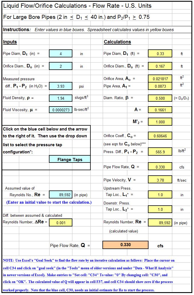
18 17
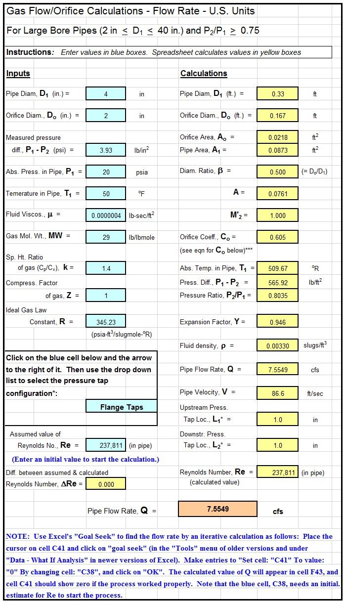
19 Note that the calculation is already pretty extensive to calculate the flow rate of a liquid through an orifice meter, because of the complication of obtaining a value for the orifice coefficient, C o. Additional steps are added for calculation of the flow rate of a gas through an orifice meter, as illustrated in Example #2 for gas flow through a venturi meter and in the next example for calculating the flow rate of air through an orifice meter with the same pipe and orifice diameters and same measured pressure difference as for water flow in Example #5. Example #6: Air at 50 o F is flowing through an orifice meter with flange taps and a 2 inch throat diameter, in a 4 inch diameter pipe. What is the flow rate through the meter if the pressure difference, P 1 P 2, is measured as 3.93 psi and the upstream pressure in the pipe, P 1, is 20 psia? Solution: The calculations will be similar to those used for Example #5, but using Equation (3) for gas flow rather than Equation (7) for liquid flow through an orifice meter. As in Example #5: A 2 = πd 22 /4 = π(2/12) 2 /4 = ft 2. β = 2/4 = 0.5, and the pressure difference, P 1 P 2, is 3.93 psi. In order to use Equation (3) to calculate the flow rate of air through the venturi meter, values are needed for the following parameters in addition to the values identified above for A 2, β, and P 1 P 2, the given value of 20 psia for P 1 and the value given above for the ideal gas law constant, R ( psia-ft 3 /slugmole- o R). the compressibility factor of the air, Z the molecular weight of the air, MW the approach temperature of the air in o R, T 1 the expansion factor, Y the viscosity of air at 50 o F (4 x 10⁻⁷ lb-sec/ft 2 ) For a temperature of 50 o F and pressure of 20 psia, the compressibility factor for air can be taken to be one. The molecular weight of air is often rounded off to 29. The absolute temperature T 1 = o R = 510 o R. 18
20 In order to use Equation (4) to calculate the expansion factor, Y, the ratio, P 2 /P 1, can be calculated as: P2/P1 = P 1 (P 2 P 1 )/P 1 = [(20*144) 565.8]/(20*144) = Using k = 1.4 for air and substituting values for k, P 2 /P 1, and β into Equation (4) gives: Y = 1 ( (0.5) (0.5) 8 )[1 (0.8035) 1/1.4 ] = Now an iterative calculation like that used in Example #5 is needed to get values for C o and Q. Again, use of an Excel spreadsheet is a convenient way to carry out this calculation including the required iteration. The following figure is a screenshot showing the Excel spreadsheet solution to Example #6, showing the solution as: Q = 7.55 cfs. 19
21 20
22 Flow Nozzle Meter: The flow nozzle meter is simpler and less expensive than a venturi meter, but not quite as simple as an orifice meter. It consists of a relatively short nozzle, typically held in place between pipe flanges, as shown in Figure 4. Figure 4. Flow Nozzle Meter Parameters For a flow nozzle meter, the exit diameter of the nozzle, d, is used for D 2 (giving A 2 = A n ), and the discharge coefficient is typically called a nozzle coefficient, C n, giving the following equation for a flow nozzle meter: Due to the smoother contraction of the flow, flow nozzle coefficients are significantly higher than orifice coefficients. They are not, however as high as venturi coefficients. Flow nozzle coefficients are typically in the range from 0.94 to There are several different standard flow nozzle designs. Information on pressure tap placement and calibration should be provided by the meter manufacturer. 21
23 5. Velocity Flow Meters Pitot / Pitot-Static Tubes Pitot tubes (also called pitot-static tubes) are an inexpensive, convenient way to measure velocity at a point in a fluid. They are used in airflow measurements in ventilation and HVAC applications. Definitions for three types of pressure and how to measure those three different kinds of pressure are given below, because understanding them helps to understand the pitot tube equation. Static pressure, dynamic pressure and total pressure are defined below and illustrated in Figure 5. Static pressure is the fluid pressure relative to surrounding atmospheric pressure, measured through a flat opening, which is in parallel with the fluid flow, as shown with the first U-tube manometer in Figure 5. Stagnation pressure is the fluid pressure relative to the surrounding atmospheric pressure, measured through a flat opening, which is perpendicular to and facing into the direction of fluid flow, as shown with the second U-tube manometer in Figure 5. This is also sometimes called the total pressure. Dynamic pressure is the fluid pressure relative to the static pressure, measured through a flat opening, which is perpendicular to and facing into the direction of fluid flow, as shown with the third U-tube manometer in Figure 5. This is also sometimes called the velocity pressure. Figure 5. Various Pressure Measurements 22
24 Static pressure is typically represented by the symbol, p. Dynamic pressure is equal to ½ ρv 2. Stagnation pressure, represented here by P stag, is equal to static pressure plus dynamic pressure plus the pressure due to a column of fluid of height, h, equal to the elevation of the static pressure tap above the stagnation pressure tap, as shown in the following equation. Where the parameters with a consistent set of units are as follows: P stag = stagnation pressure, lb/ft 2 P = static pressure, lb/ft 2 ρ = density of fluid, slugs/ft 3 γ = specific weight of fluid, lb/ft 3 h = elevation of static pressure tap above stagnation pressure tap, ft V = average velocity of fluid, ft/sec (V = Q/A = volumetric flow rate/cross-sectional area normal to flow) For pitot tube measurements, the static pressure tap and stagnation pressure tap are at the same elevation, so that h = 0. Then stagnation pressure minus static pressure is equal to dynamic pressure, or: 23
25 The pressure difference, P stag - P, can be measured directly with a pitot tube such as the third U-tube in Figure 5, or more simply with a pitot tube like the one shown in Figure 6, which has two concentric tubes. The inner tube has a stagnation pressure opening and the outer tube has a static pressure opening parallel to the fluid flow direction. The pressure difference is equal to the dynamic pressure (½ ρv 2 ) and can be used to calculate the fluid velocity for known fluid density, ρ. A consistent set of units is: pressure in lb/ft 2, density in slugs/ft 3, and velocity in ft/sec. Figure 6. Pitot Tube For use with a pitot tube, Equation (11) will typically be used to calculate the velocity of the fluid. Setting (P stag P) = P, and solving for V, gives the following equation: In order to use Equation (12) to calculate fluid velocity from pitot tube measurements, it is necessary to be able to obtain a value of density for the flowing fluid at its temperature and pressure. For a liquid, a value for density can typically be obtained from a table similar to Table 1 in this course. Such tables are available in handbooks and fluid mechanics or thermodynamics textbooks. Pitot tubes are used more commonly, however, to measure gas flow, as for 24
26 example, air flow in HVAC ducts, and density of a gas varies considerably with both temperature and pressure. A convenient way to obtain a value of density for a gas at known temperature and pressure is through the use of the Ideal Gas Law. The Ideal Gas Law, as used to calculate density of a gas is as follows: Where: ρ = density of the gas at pressure, P, & temperature, T, slugs/ft 3 MW = molecular weight of the gas, slugs/slug-mole (The average molecular weight typically used for air is 29.) P = absolute pressure of the gas, psia T = absolute temperature of the gas, o R ( o F = o R) R = Ideal Gas Law constant, psia-ft 3 /slug-mole- o R But, you may ask, this is the Ideal Gas Law, so how can we use it to find the density of real gases? Well, the Ideal Gas Law is a very good approximation for many real gases over a wide range of temperatures and pressures. It does not work well for very high pressures or very low temperatures (approaching the critical temperature and/or critical pressure for the gas), but for many practical, real situations, the Ideal Gas Law gives quite accurate values for density of a gas. Example #7: Estimate the density of air at 16 psia and 85 o F. Solution: Convert 85 o F to o R: 85 o F = o R = o R Substituting values for P, T, R, & MW into Equation (13) gives: 25
27 ρ = (29)[16/(345.23)(544.67)] = slugs/ft 3 Example #8: A pitot tube is being used to measure air velocity in a heating duct. The air is at 85 o F and 16 psia. The pitot tube registers a pressure difference of inches of water (P stag P). What is the velocity of the air at that point in the duct? Solution: Convert inches of water to lb/ft 2 (psf) (conversion factor is: psf/in of water): in of water = (0.023)(5.204) psf = psf Air density at the given P & T is slugs/ft 3 from Example #5. Substituting into Equation (12), to calculate the velocity, gives: 6. Variable Area Flow Meter - Rotameters A rotameter is a variable area flow meter. It consists of a tapered glass or plastic tube with a float that moves upward to an equilibrium position determined by the flow rate of fluid going through the meter. For greater flow rate, a larger crosssectional area is needed for the flow, so the float is moved upward until the upward force on it by the fluid is equal to the force of gravity pulling it down. Note that the float must have a density greater than the fluid, or it would simply float to the top of the fluid. Given below, in Figure 7, is a schematic diagram of a rotameter, showing the principle of its operation. The height of the float as measured by a graduated scale on the side of the rotameter can be calibrated for the flow rate of the fluid being measured in appropriate flow units. A few points regarding rotameters follow: 26
28 Because of the key role of gravity, rotameters must be installed vertically. Typical turndown ratio is 10:1, that is, flow rates as low as 1/10 of the maximum reading can be accurately measured. Accuracy as good as 1% of full scale reading can be expected. Rotameters do not require power, so they are safer to use with flammable fluids, than an instrument using power, which would need to be explosion proof. A rotameter causes little pressure drop. It is difficult to apply machine reading and continuous recording with a rotameter. Figure 7. Rotameter Schematic diagram 27
29 7. Positive Displacement Flow Meters Positive displacement flow meters are often used in residential and small commercial applications. They are very accurate at low to moderate flow rates, which are typical of these applications. There are several types of positive displacement meters, such as reciprocating piston, nutating disk, oval gear, and rotary vane. In all of them, the water passing through the meter, physically displaces a known volume of fluid for each rotation of the moving measuring element. The number of rotations is counted electronically or magnetically and converted to the volume that has passed through the meter and/or flow rate. Positive displacement meters can be used for any relatively nonabrasive fluid, such as heating oils, Freon, printing ink, or polymer additives. The accuracy is very good, approximately 0.1% of full flow rate with a turndown of 70:1 or more. On the other hand, positive displacement flow meters are expensive compared to many other types of meters and produce the highest pressure drop of any flow meter type. 8. Miscellaneous Types of Flow meters In this section several more types of flow meters for use with pipe flow will each be described and discussed briefly. a) Electromagnetic flow meters An electromagnetic flow meter (also called magnetic meter or mag meter ) measures flow rate by measuring the voltage generated by a conductive fluid passing through a magnetic field. The magnetic field is created by coils outside the flow tube, carrying electrical current. The generated voltage is proportional to the flow rate of the conductive fluid passing through the flow tube. An external sensor measures the generated voltage and converts it to flow rate. 28
30 In order to be measured by an electromagnetic flow meter, the fluid must have a conductivity of at least 5 µs/cm. Thus, this type of meter will not work for distilled or deionized water or for most non-aqueous liquids. It works well for water that has not been distilled or deionized and many aqueous solutions. Since there is no internal sensor to get fouled, an electromagnetic flow meter is quite suitable for wastewater, other dirty liquids, corrosive liquids or slurries. Since there is no constriction or obstruction to the flow through an electromagnetic meter, it creates negligible pressure drop. It does, however, have a relatively high power consumption, in comparison with other types of flow meters. b) Target flow meters With a target flow meter, a physical target (disk) is placed directly in the path of the fluid flow. The target will be deflected due to the force of fluid striking it, and the greater the fluid flow rate, the greater the deflection will be. The deflection is measured by a sensor mounted on the pipe and calibrated to flow rate for a given fluid. Figure 8 shows a diagram of a target flow meter. Figure 8. Target Flow Meter A target flow meter can be used for a wide variety of liquids or gases and there are no moving parts to wear out. They typically have a turndown of 10:1 to 15:1. 29
31 c) Turbine flow meters A turbine flow meter operates on the principle that a fluid flowing past the blades of a turbine will cause it to rotate. Increasing flow rate will cause increasing rate of rotation for the turbine. The meter thus consists of a turbine placed in the path of flow and means of measuring the rate of rotation of the turbine. The turbine s rotational rate can then be calibrated to flow rate. The turbine meter has one of the higher turndown ratios, typically 20:1 or more. Its accuracy is also among the highest at about %. d) Vortex flow meters An obstruction in the path of a flowing fluid will create vortices in the downstream flow if the fluid flow speed is above a critical value. A vortex flow meter (also known as vortex shedding or oscillatory flow meter), measures the vibrations of the downstream vortices caused by a barrier in the flow path, as illustrated in Figure 9. The vibrating frequency of the downstream vortices will increase with increasing flow rate, and can thus be calibrated to flow rate of the fluid. Figure 9. Vortex Flow Meter 30
32 e) Ultrasonic flow meters The two major types of ultrasonic flow meters are Doppler and transit-time ultrasonic meters. Both use ultrasonic waves (frequency > 20 khz). Both types also use two transducers that transmit and/or receive the ultrasonic waves. For the Doppler ultrasonic meter, one transducer transmits the ultrasonic waves and the other receives the waves. The fluid must have material in it that will reflect sonic waves, such as particles or entrained air. The frequency of the transmitted beam of ultrasonic waves will be altered, by being reflected from the particles or air bubbles. The resulting frequency shift is measured by the receiving transducer, and is proportional to the flow rate through the meter. A signal can thus be generated from the receiving transducer, which is proportional to flow rate. Transit-time ultrasonic meters, also known as time-of-travel meters, measure the difference in travel time between pulses transmitted in the direction of flow and pulses transmitted against the flow. The two transducers are mounted so that one 31
33 is upstream of the other. Both transducers serve alternately as transmitter and receiver. The upstream transducer will transmit a pulse, which is detected by the downstream transducer, acting as a receiver, giving a transit-time in the direction of flow. The downstream transducer will then transmit a pulse, which is detected by the upstream transducer (acting as a receiver), to give a transit-time against the flow. The difference between the upstream and downstream transit times can be correlated to flow rate through the meter. The components of a transit-time ultrasonic flow meter are shown in Figure 10. One of the options with this type of meter is a rail-mounted set of transducers, which can be clamped onto an existing pipe without taking the pipe apart to mount the meter. It could be used in this way to check on or calibrate an existing meter, or as a permanent installation for flow measurement. Ultrasonic flow meters are also available with transducers permanently mounted on an insert that is mounted in the pipeline, much like other flow meters, such as an electromagnetic flow meter. Like the electromagnetic flow meter, ultrasonic meters have no sensors inside the pipe nor any constrictions or obstructions in the pipe, so they are suitable for dirty or corrosive liquids or slurries. Also, they cause negligible pressure drop. Figure 11. Transit-time Ultrasonic Flow Meter 32
34 f) Mass flow meters The two types of mass flow meters will be described and discussed here. They are the coriolis mass flow meter and thermal mass flow meter. Both of these types of flow meters measure mass flow rate rather than volumetric flow rate. Coriolis flow meters make use of the Coriolis effect (a coriolis force that acts on objects that are in motion relative to a rotating frame of reference. A coriolis flow meter typically functions by generating a vibration of the tube or tubes that the fluid is flowing through. Often the part of the tube that is vibrated is curved. The amount of twist caused by the coriolis force is measured and is proportional to the mass flow rate passing through the tube(s). Quite a variety of different designs are used for coriolis mass flow meters. Coriolis flow meters are among the most accurate of the types of flow meters and have a very high turndown ratio (range from minimum to maximum readable flow rate for a given meter). Thermal mass flow meter typically include a means of heat input to the flowing fluid and for temperature measurement at two or more points. The amount of temperature increase and rate of heat input to the fluid are measured and can be correlated with the flow rate of the fluid through its thermal properties. Thermal mass flow meters are among the most accurate types of flow meters, have a very high turndown ratio (range from minimum to maximum readable flow rate for a given meter), and have a medium cost. On the other hand, they are only useable for the flow of clean gases and do not work well for gas mixtures if the gas composition varies with time 9. Comparison of Flow Meter Alternatives Table 2 shows a summary of several useful characteristics of the different types of pipe flow meters described and discussed in this course. The information in Table 2 was extracted from similar tables at the Omega Engineering and ICENTA web sites at: 33
35 and The flow meter characteristics summarized in Table 2 are: recommended applications, typical turndown ratio (also called rangeability), pressure drop, typical accuracy, upstream pipe diameters (required upstream straight pipe length), effect of viscosity, and relative cost. 34
36 10. Summary There are a wide variety of meter types for measuring flow rate in closed conduits. Fourteen of those types were described and discussed in this course. This included a considerable amount of detail about pressure differential flow meters (venturi, orifice and flow nozzle meters), such as equations and example calculations for liquid flow and for gas flow through differential flow meters. 35
37 Table 2 in Section 9, summarizes a comparison among those fourteen types of flow meters: Orifice meter, Venturi meter, Flow nozzle meter, Pitot tube, Rotameter, Electromagnetic flow meter, Target meter, Turbine meter, Vortex flow meter, Ultrasonic (Doppler) flow meter, Ultrasonic (time of travel) flow meter, Coriolis mass flow meter, and Thermal mass flow meter. For each of these types of flow meters, Table 2 provides information about i) recommended applications, ii) typical turndown ratio, iii) whether its pressure drop is high, medium, low, or none, iv) typical accuracy in %, v) required upstream pipe diameters of straight pipe, vi) effect of viscosity, and vii) relative cost. 36
38 References 1. Bengtson, H.H., Excel Spreadsheets for Orifice and Venturi Flow Meters, an online informational article at 2. Bengtson, H.H., "Spreadsheets for ISO 5167 Orifice Plate Flow Meter Calculations," an online informational article at: 3. Munson, B. R., Young, D. F., & Okiishi, T. H., Fundamentals of Fluid Mechanics, 4 th Ed., New York: John Wiley and Sons, Inc, International Organization of Standards - ISO :2003 Measurement of fluid flow by means of pressure differential devices inserted in circular crosssection conduits flowing full, Part 2: Orifice plates. Reference number: ISO : International Organization of Standards - ISO :2003 Measurement of fluid flow by means of pressure differential devices inserted in circular crosssection conduits flowing full, Part 4: Venturi Tubes. Reference number: ISO : U.S. Dept. of the Interior, Bureau of Reclamation, 2001 revised, 1997 third edition, Water Measurement Manual, available for on-line use or download at: 7. LMNO Engineering, Research and Software, Ltd website. Contains equations and graphs for flow measurement with venturi, orifice and flow nozzle flowmeters Engineering Toolbox website. Contains information on flow measurement with a variety of meter types. 37
Flow Measurement in Pipes and Ducts COURSE CONTENT
 Flow Measurement in Pipes and Ducts Dr. Harlan H. Bengtson, P.E. COURSE CONTENT 1. Introduction This course is about measurement of the flow rate of a fluid flowing under pressure in a closed conduit.
Flow Measurement in Pipes and Ducts COURSE CONTENT
 Flow Measurement in Pipes and Ducts Dr. Harlan H. Bengtson, P.E. COURSE CONTENT 1. Introduction This course is about measurement of the flow rate of a fluid flowing under pressure in a closed conduit.
Orifice and Venturi Pipe Flow Meters
 Orifice and Venturi Pipe Flow Meters For Liquid and Gas Flow by Harlan H. Bengtson, PhD, P.E. 1. Introduction Orifice and Venturi Pipe Flow Meters The flow rate of a fluid flowing in a pipe under pressure
Orifice and Venturi Pipe Flow Meters
 Orifice and Venturi Pipe Flow Meters by Harlan H. Bengtson, PhD, P.E. 1. Introduction Your Course Title Here The flow rate of a fluid flowing in a pipe under pressure is measured for a variety of applications,
Applied Fluid Mechanics
 Applied Fluid Mechanics 1. The Nature of Fluid and the Study of Fluid Mechanics 2. Viscosity of Fluid 3. Pressure Measurement 4. Forces Due to Static Fluid 5. Buoyancy and Stability 6. Flow of Fluid and
Applied Fluid Mechanics
 Applied Fluid Mechanics 1. The Nature of Fluid and the Study of Fluid Mechanics 2. Viscosity of Fluid 3. Pressure Measurement 4. Forces Due to Static Fluid 5. Buoyancy and Stability 6. Flow of Fluid and
CHAPTER (13) FLOW MEASUREMENTS
 FLOW MEASUREMENTS") CHAPTER (13) FLOW MEASUREMENTS 09/12/2010 Dr. Munzer Ebaid 1 Instruments for the Measurements of Flow Rate 1. Direct Methods: Volume or weight measurements. 2. Indirect Methods: Venturi meters, Orifices
CHAPTER (13) FLOW MEASUREMENTS 09/12/2010 Dr. Munzer Ebaid 1 Instruments for the Measurements of Flow Rate 1. Direct Methods: Volume or weight measurements. 2. Indirect Methods: Venturi meters, Orifices
Instrumentation & Data Acquisition Systems
 Instrumentation & Data Acquisition Systems Section 5 -Flow Robert W. Harrison, PE Bob@TheHarrisonHouse.com Made in USA 1 The Perfect Flowmeter Infinite rangeability / turndown with negligible uncertainty
Fundamentals of Flow Metering
 Technical Data Sheet 00816-0100-3031 Fundamentals of Flow Metering A reliable flow indication is dependent upon the correct measurement of A and V. If, for example, air bubbles are present in the fluid,
SELECCIÓN DE CAUDALIMETROS. Tablas de Fabricantes
 SELECCIÓN DE CAUDALIMETROS Tablas de Fabricantes Flow Meter Selection Table http://www.instrumart.com/content.aspxcontentid=219 Página 1 de 1 17/09/2007 KEY Best for this application OK with some exceptions
FLOW MEASUREMENT. INC 102 Fundamental of Instrumentation and Process Control 2/2560
 FLOW MEASUREMENT INC 102 Fundamental of Instrumentation and Process Control 2/2560 TABLE OF CONTENTS A. INTRODUCTION B. LOCAL FLOW MEASUREMENT B.1 Particle Image Velocimetry (PIV) B.2 Laser doppler anemometry
Lecture 13 Flow Measurement in Pipes. I. Introduction
 Lecture 13 Flow Measurement in Pipes I. Introduction There are a wide variety of methods for measuring discharge and velocity in pipes, or closed conduits Many of these methods can provide very accurate
Experiment No.4: Flow through Venturi meter. Background and Theory
 Experiment No.4: Flow through Venturi meter Background and Theory Introduction Flow meters are used in the industry to measure the volumetric flow rate of fluids. Differential pressure type flow meters
An Essential Requirement in CV Based Industrial Appliances.
 Measurement of Flow P M V Subbarao Professor Mechanical Engineering Department An Essential Requirement in CV Based Industrial Appliances. Mathematics of Flow Rate The Scalar Product of two vectors, namely
Engineers Edge, LLC PDH & Professional Training
 510 N. Crosslane Rd. Monroe, Georgia 30656 (770) 266-6915 fax (678) 643-1758 Engineers Edge, LLC PDH & Professional Training Copyright, All Rights Reserved Engineers Edge, LLC Pipe Flow-Friction Factor
ME411 Engineering Measurement & Instrumentation. Winter 2017 Lecture 11
 ME411 Engineering Measurement & Instrumentation Winter 2017 Lecture 11 1 Flow Measurement Identify an effect that depends on flow rate Process control requires accurate measurement of flow control Mixing
Lecture23. Flowmeter Design.
 Lecture23 Flowmeter Design. Contents of lecture Design of flowmeter Principles of flow measurement; i) Venturi and ii) Orifice meter and nozzle Relationship between flow rate and pressure drop Relation
Pipe Flow/Friction Factor Calculations using Excel Spreadsheets
 Pipe Flow/Friction Factor Calculations using Excel Spreadsheets Harlan H. Bengtson, PE, PhD Emeritus Professor of Civil Engineering Southern Illinois University Edwardsville Table of Contents Introduction
Volume and Mass Flow Rate Measurement Author: John M. Cimbala, Penn State University Latest revision: 07 December 2007
 Volume and Mass Flow Rate Measurement Author: John M. Cimbala, Penn State University Latest revision: 07 ecember 2007 Introduction and notation In many engineering applications, either mass flow rate or
ABB Flowmeters Review of industrial processing flowmeters
 White paper ABB Flowmeters Review of industrial processing flowmeters Understanding flowmeters and their pros and cons By Ron DiGiacomo, ABB Measurement Products One of the most critical measurements in
Open Channel Hydraulics III - Sharpcrested
 PDHonline Course H140 (2 PDH) Open Channel Hydraulics III - Sharpcrested Weirs Instructor: Harlan H. Bengtson, Ph.D., PE 2012 PDH Online PDH Center 5272 Meadow Estates Drive Fairfax, VA 22030-6658 Phone
Mechanical Measurements and Metrology Prof. S. P. Venkateshan Department of Mechanical Engineering Indian Institute of Technology, Madras
 Mechanical Measurements and Metrology Prof. S. P. Venkateshan Department of Mechanical Engineering Indian Institute of Technology, Madras Module - 3 Lecture - 33 Measurement of Volume and Mass Flow Rate
ME332 FLUID MECHANICS LABORATORY (PART I)
") ME332 FLUID MECHANICS LABORATORY (PART I) Mihir Sen Department of Aerospace and Mechanical Engineering University of Notre Dame Notre Dame, IN 46556 Version: January 14, 2002 Contents Unit 1: Hydrostatics
ME332 FLUID MECHANICS LABORATORY (PART I) Mihir Sen Department of Aerospace and Mechanical Engineering University of Notre Dame Notre Dame, IN 46556 Version: January 14, 2002 Contents Unit 1: Hydrostatics
Experiment (4): Flow measurement
: Flow measurement") Experiment (4): Flow measurement Introduction: The flow measuring apparatus is used to familiarize the students with typical methods of flow measurement of an incompressible fluid and, at the same time
Experiment (4): Flow measurement Introduction: The flow measuring apparatus is used to familiarize the students with typical methods of flow measurement of an incompressible fluid and, at the same time
Open Channel Flow I - The Manning Equation and Uniform Flow COURSE CONTENT
 Open Channel Flow I - The Manning Equation and Uniform Flow Harlan H. Bengtson, PhD, P.E. COURSE CONTENT 1. Introduction Flow of a liquid may take place either as open channel flow or pressure flow. Pressure
AEROSPACE ENGINEERING DEPARTMENT. Second Year - Second Term ( ) Fluid Mechanics & Gas Dynamics
 Fluid Mechanics & Gas Dynamics") AEROSPACE ENGINEERING DEPARTMENT Second Year - Second Term (2008-2009) Fluid Mechanics & Gas Dynamics Similitude,Dimensional Analysis &Modeling (1) [7.2R*] Some common variables in fluid mechanics include:
AEROSPACE ENGINEERING DEPARTMENT Second Year - Second Term (2008-2009) Fluid Mechanics & Gas Dynamics Similitude,Dimensional Analysis &Modeling (1) [7.2R*] Some common variables in fluid mechanics include:
Measurements using Bernoulli s equation
 An Internet Book on Fluid Dynamics Measurements using Bernoulli s equation Many fluid measurement devices and techniques are based on Bernoulli s equation and we list them here with analysis and discussion.
VENTURIMETER EXPERIMENT
 ENTURIMETER EXERIMENT. OBJECTİE The main objectives of this experiment is to obtain the coefficient of discharge from experimental data by utilizing venturi meter and, also the relationship between Reynolds
5 ENERGY EQUATION OF FLUID MOTION
 5 ENERGY EQUATION OF FLUID MOTION 5.1 Introduction In order to develop the equations that describe a flow, it is assumed that fluids are subject to certain fundamental laws of physics. The pertinent laws
Mass of fluid leaving per unit time
 5 ENERGY EQUATION OF FLUID MOTION 5.1 Eulerian Approach & Control Volume In order to develop the equations that describe a flow, it is assumed that fluids are subject to certain fundamental laws of physics.
Flow Monitoring Technologies in Oil and Gas. Don Ford, Technical Specialist Spartan Controls Ltd.
 Flow Monitoring Technologies in Oil and Gas Don Ford, Technical Specialist Spartan Controls Ltd. Agenda Flow technologies at a glance Oil and Gas at a glance Select Flow Technologies in Depth Differential
FLOW MEASUREMENT INC 331 Industrial process measurement 2018
 FLOW MEASUREMENT INC 331 Industrial process measurement 2018 1 TABLE OF CONTENTS A. INTRODUCTION B. LOCAL FLOW MEASUREMENT B.1 Particle Image Velocimetry (PIV) B.2 Laser doppler anemometry (LDA) B.3 Hot-wire
9.1 Introduction. 9.2 Fluid Flow. CHAPTER 9 Flow
 CHAPTER 9 9.1 Introduction The accurate measurement of fluid flow is very important in many industrial applications. Optimum performance of many processes requires specific flow rates. The cost of many
Lab Section Date. ME4751 Air Flow Rate Measurement
 Name Lab Section Date ME4751 Air Flow Rate Measurement Objective The objective of this experiment is to determine the volumetric flow rate of air flowing through a pipe using a Pitot-static tube and a
FINAL DRAFT: October 25, 2010 API TECHNICAL REPORT FUEL GAS MEASUREMENT. FINAL DRAFT: October 25, 2010 Page 0
 FINAL DRAFT: October 25, 2010 API TECHNICAL REPORT FUEL GAS MEASUREMENT FINAL DRAFT: October 25, 2010 Page 0 Foreword Add API boiler plate FINAL DRAFT: October 25, 2010 Page 1 TABLE OF CONTENTS Introduction...
EXPERIMENT NO. 4 CALIBRATION OF AN ORIFICE PLATE FLOWMETER MECHANICAL ENGINEERING DEPARTMENT KING SAUD UNIVERSITY RIYADH
 EXPERIMENT NO. 4 CALIBRATION OF AN ORIFICE PLATE FLOWMETER MECHANICAL ENGINEERING DEPARTMENT KING SAUD UNIVERSITY RIYADH Submitted By: ABDULLAH IBN ABDULRAHMAN ID: 13456789 GROUP A EXPERIMENT PERFORMED
Open Channel Flow Measurement Weirs and Flumes
 Open Channel Flow Measurement Weirs and Flumes by Harlan H. Bengtson, PhD, P.E. 1. Introduction Measuring the flow rate of water in an open channel typically involves some type of obstruction in the path
04/01/1998 Developments in DP Flowmeters By Jesse Yoder
 04/01/1998 Developments in DP Flowmeters By Jesse Yoder Developments in DP Flowmeters Improvements in Primary Elements Are Keeping Differential Pressure Flowmeters the First Choice for Many Process Applications
ABSTRACT I. INTRODUCTION
 2016 IJSRSET Volume 2 Issue 4 Print ISSN : 2395-1990 Online ISSN : 2394-4099 Themed Section: Engineering and Technology Analysis of Compressible Effect in the Flow Metering By Orifice Plate Using Prasanna
MCE380: Measurements and Instrumentation Lab
 MCE380: Measurements and Instrumentation Lab Chapter 8: Flow Measurements Topics: Basic Flow Equations Flow Obstruction Meters Positive Displacement Flowmeters Other Methods Holman, Ch. 7 Cleveland State
EXPERIMENT No.1 FLOW MEASUREMENT BY ORIFICEMETER
 EXPERIMENT No.1 FLOW MEASUREMENT BY ORIFICEMETER 1.1 AIM: To determine the co-efficient of discharge of the orifice meter 1.2 EQUIPMENTS REQUIRED: Orifice meter test rig, Stopwatch 1.3 PREPARATION 1.3.1
CHAPTER 3 BASIC EQUATIONS IN FLUID MECHANICS NOOR ALIZA AHMAD
 CHAPTER 3 BASIC EQUATIONS IN FLUID MECHANICS 1 INTRODUCTION Flow often referred as an ideal fluid. We presume that such a fluid has no viscosity. However, this is an idealized situation that does not exist.
COURSE CODE : 3072 COURSE CATEGORY : B PERIODS/ WEEK : 5 PERIODS/ SEMESTER : 75 CREDIT : 5 TIME SCHEDULE
 COURSE TITLE : FLUID MECHANICS COURSE CODE : 307 COURSE CATEGORY : B PERIODS/ WEEK : 5 PERIODS/ SEMESTER : 75 CREDIT : 5 TIME SCHEDULE MODULE TOPIC PERIOD 1 Properties of Fluids 0 Fluid Friction and Flow
The Expansibility Factor Equations in ISO and ISO : Do They Deliver What They Promise?
 The Expansibility Factor Equations in ISO 567-2 and ISO 567-4: Do They Deliver What They Promise? Michael Reader-Harris, NEL INTRODUCTION The expansibility factor equations in ISO 567-2:2003 [] and ISO
Open Channel Hydraulics I - Uniform Flow
 PDHonline Course H138 (2 PDH) Open Channel Hydraulics I - Uniform Flow Instructor: Harlan H. Bengtson, Ph.D., PE 2012 PDH Online PDH Center 5272 Meadow Estates Drive Fairfax, VA 22030-6658 Phone & Fax:
Given Find Water Properties
 Venturi Example Given: A venturi is to be used to measure a 50 gpm flow of 70 F water in a 4-in ID pipe. Find: Select a throat diameter that provides Re d > 00,000 in the throat, and determine what differential
Compressible Gas Flow
 Compressible Gas Flow by Elizabeth Adolph Submitted to Dr. C. Grant Willson CHE53M Department of Chemical Engineering The University of Texas at Austin Fall 008 Compressible Gas Flow Abstract In this lab,
FLOW MEASUREMENT IN PIPES EXPERIMENT
 University of Leicester Engineering Department FLOW MEASUREMENT IN PIPES EXPERIMENT Page 1 FORMAL LABORATORY REPORT Name of the experiment: FLOW MEASUREMENT IN PIPES Author: Apollin nana chaazou Partner
Flow Measurement: Physical principle employed in various types of flow meters. PART 4 PREPARED BY: ESO OLUWATOBILOBA
 Flow Measurement: Physical principle employed in various types of flow meters. PART 4 PREPARED BY: ESO OLUWATOBILOBA Pressure Differential Flow Meters In a differential pressure drop device the flow is
Given Find Water Properties
 Venturi Example Given: A venturi is to be used to measure a 50 gpm flow of 70 F water in a 4-in ID pipe. Find: Select a throat diameter that provides Re d > 00,000 in the throat, and determine what differential
Roll No. :... Invigilator s Signature :.. CS/B.Tech (EIE)/SEM-5/EI-501/ INDUSTRIAL INSTRUMENTATION II
/SEM-5/EI-501/ INDUSTRIAL INSTRUMENTATION II") Name : Roll No. :.... Invigilator s Signature :.. CS/B.Tech (EIE)/SEM-5/EI-501/2011-12 2011 INDUSTRIAL INSTRUMENTATION II Time Allotted : 3 Hours Full Marks : 70 The figures in the margin indicate full
Name : Roll No. :.... Invigilator s Signature :.. CS/B.Tech (EIE)/SEM-5/EI-501/2011-12 2011 INDUSTRIAL INSTRUMENTATION II Time Allotted : 3 Hours Full Marks : 70 The figures in the margin indicate full
Laboratory 1: Calibration of a High-Volume Sampler
 Laboratory 1 Laboratory 1: Calibration of a High-Volume Sampler 1.1 To the User of this Manual This manual has been prepared to guide the students through a series of laboratory exercises developed to
Flowmeter Discharge Coefficient Estimation
 Bankston 1 Flowmeter Discharge Coefficient Estimation Elizabeth Bankston Team 1 Abstract An Edibon FME18 Flow Meter demonstration system was used to obtain experimental values for this experiment. The
Flow : the motion of a fluid (1) Blood flowmeters : - ultrasonic (doppler, transit time) -electromagnetic (2) Gas flowmeters : - pneumotachometer
 Blood flowmeters : - ultrasonic (doppler, transit time) -electromagnetic (2) Gas flowmeters : - pneumotachometer") Flow Sensors Flow : the motion of a fluid (1) Blood flowmeters : - ultrasonic (doppler, transit time) -electromagnetic (2) Gas flowmeters : - pneumotachometer -spirometer - Wright's respirometer - rotameter
Flow Sensors Flow : the motion of a fluid (1) Blood flowmeters : - ultrasonic (doppler, transit time) -electromagnetic (2) Gas flowmeters : - pneumotachometer -spirometer - Wright's respirometer - rotameter
If a stream of uniform velocity flows into a blunt body, the stream lines take a pattern similar to this: Streamlines around a blunt body
 Venturimeter & Orificemeter ELEMENTARY HYDRAULICS National Certificate in Technology (Civil Engineering) Chapter 5 Applications of the Bernoulli Equation The Bernoulli equation can be applied to a great
Chapter 3 Bernoulli Equation
 1 Bernoulli Equation 3.1 Flow Patterns: Streamlines, Pathlines, Streaklines 1) A streamline, is a line that is everywhere tangent to the velocity vector at a given instant. Examples of streamlines around
Process Gas Flow Measurement and Performance Evaluation API TECHNICAL REPORT 2571 SECOND EDITION DRAFT, FEBRUARY 2018
 Process Gas Flow Measurement and Performance Evaluation API TECHNICAL REPORT 2571 SECOND EDITION DRAFT, FEBRUARY 2018 (Note: modify document as needed once final proposal on name change is agreed, i.e.
FE Fluids Review March 23, 2012 Steve Burian (Civil & Environmental Engineering)
") Topic: Fluid Properties 1. If 6 m 3 of oil weighs 47 kn, calculate its specific weight, density, and specific gravity. 2. 10.0 L of an incompressible liquid exert a force of 20 N at the earth s surface.
Topic: Fluid Properties 1. If 6 m 3 of oil weighs 47 kn, calculate its specific weight, density, and specific gravity. 2. 10.0 L of an incompressible liquid exert a force of 20 N at the earth s surface.
Today s menu. Last lecture. Measurement of volume flow rate. Measurement of volume flow rate (cont d...) Differential pressure flow meters
 Differential pressure flow meters") Last lecture Analog-to-digital conversion (Ch. 1.1). Introduction to flow measurement systems (Ch. 12.1). Today s menu Measurement of volume flow rate Differential pressure flowmeters Mechanical flowmeters
Last lecture Analog-to-digital conversion (Ch. 1.1). Introduction to flow measurement systems (Ch. 12.1). Today s menu Measurement of volume flow rate Differential pressure flowmeters Mechanical flowmeters
Chapter 4 DYNAMICS OF FLUID FLOW
 Faculty Of Engineering at Shobra nd Year Civil - 016 Chapter 4 DYNAMICS OF FLUID FLOW 4-1 Types of Energy 4- Euler s Equation 4-3 Bernoulli s Equation 4-4 Total Energy Line (TEL) and Hydraulic Grade Line
Fluid Flow Analysis Penn State Chemical Engineering
 Fluid Flow Analysis Penn State Chemical Engineering Revised Spring 2015 Table of Contents LEARNING OBJECTIVES... 1 EXPERIMENTAL OBJECTIVES AND OVERVIEW... 1 PRE-LAB STUDY... 2 EXPERIMENTS IN THE LAB...
Large Rocket Engine Environments
 Balanced Flow Metering and Conditioning Technology for Fluid Systems (Space Liquid Propulsion Systems) for 2006 Instrumentation Symposium for the Process Industries Anthony R. Kelley EV23 Advanced Sensors
ME332 FLUID MECHANICS LABORATORY (PART II)
") ME332 FLUID MECHANICS LABORATORY (PART II) Mihir Sen Department of Aerospace and Mechanical Engineering University of Notre Dame Notre Dame, IN 46556 Version: April 2, 2002 Contents Unit 5: Momentum transfer
ME332 FLUID MECHANICS LABORATORY (PART II) Mihir Sen Department of Aerospace and Mechanical Engineering University of Notre Dame Notre Dame, IN 46556 Version: April 2, 2002 Contents Unit 5: Momentum transfer
Annubar Primary Element Flow Calculations
 Rosemount 485 Annubar Annubar Primary Element Flow Calculations ANNUBAR PRIMARY ELEMENT FLOW EQUATIONS The Annubar primary element flow equations are all derived from the hydraulic equations which are
Computation of pressure loss for differential producing flowmeters
 XXVI. ASR '00 Seminar, Instruments and Control, Ostrava, April 6-7, 00 Paper 5 Computation of pressure loss for differential producing flowmeters ORLÍKOVÁ, Soňa Ing., Ústav automatizace a měřicí techniky,
ISA Seminars on the Web Live Experts on Hot Topics
 ISA Seminars on the Web Live Experts on Hot Topics Standards Certification Education and Training Publishing Conferences and Exhibits CSE PE Exam Review: Measurement II EN00W3 Version 1.4 2011 Standards
405 Compact Orifice Series and 1595 Conditioning Orifice Plate Flow Test Data Book and Flow Handbook
 405 Compact Orifice Series and 1595 Conditioning Orifice Plate Flow Test Book and Flow Handbook www.rosemount.com 405 and 1595 405 Compact Orifice Series and 1595 Conditioning Orifice Plate Flow Test
DETERMINATION OF DISCHARGE AND HEAD LOSS USING A FLOW-MEASURING APPARATUS
 DETERMINATION OF DISCHARGE AND HEAD LOSS USING A FLOW-MEASURING APPARATUS 1. INTRODUCTION Through use of the Flow-Measuring Apparatus, this experiment is designed to accustom students to typical methods
2 Internal Fluid Flow
 Internal Fluid Flow.1 Definitions Fluid Dynamics The study of fluids in motion. Static Pressure The pressure at a given point exerted by the static head of the fluid present directly above that point.
Predictionof discharge coefficient of Venturimeter at low Reynolds numbers by analytical and CFD Method
 International Journal of Engineering and Technical Research (IJETR) ISSN: 2321-0869, Volume-3, Issue-5, May 2015 Predictionof discharge coefficient of Venturimeter at low Reynolds numbers by analytical
ISO 9906 INTERNATIONAL STANDARD. Rotodynamic pumps Hydraulic performance acceptance tests Grades 1 and 2
 INTERNATIONAL STANDARD ISO 9906 First edition 1999-1-15 Rotodynamic pumps Hydraulic performance acceptance tests Grades 1 and Pompes rotodynamiques Essais de fonctionnement hydraulique pour la réception
vector H. If O is the point about which moments are desired, the angular moment about O is given:
 The angular momentum A control volume analysis can be applied to the angular momentum, by letting B equal to angularmomentum vector H. If O is the point about which moments are desired, the angular moment
405 Compact Orifice Series and 1595 Conditioning Orifice Plate Flow Test Data Book and Flow Handbook
 Reference Manual 405 Compact Orifice Series and 1595 Conditioning Orifice Plate Flow Test Book and Flow Handbook www.rosemount.com Reference Manual 405 and 1595 405 Compact Orifice Series and 1595 Conditioning
Industrial Instrumentation Prof. A. Barua Department of Electrical Engineering Indian Institute of Technology Kharagpur. Lecture - 14 Flowmeter ΙΙΙ
 Industrial Instrumentation Prof. A. Barua Department of Electrical Engineering Indian Institute of Technology Kharagpur Lecture - 14 Flowmeter ΙΙΙ Welcome to lesson 14 of Industrial Instrumentation. In
ELECTRONIC FLOWMETERS FOR THERMAL ENERGY MEASUREMENT. By Dr. Crainic Monica Sabina
 ELECTRONIC FLOWMETERS FOR THERMAL ENERGY MEASUREMENT By Dr. Crainic Monica Sabina Luxten Lighting Company AEM Branch Office Gas and Water Meters Research Department 26 Calea Buziaşului300693 Timişoara
F L U I D S Y S T E M D Y N A M I C S
 F L U I D S Y S T E M D Y N A M I C S T he proper design, construction, operation, and maintenance of fluid systems requires understanding of the principles which govern them. These principles include
Lesson 37 Transmission Of Air In Air Conditioning Ducts
 Lesson 37 Transmission Of Air In Air Conditioning Ducts Version 1 ME, IIT Kharagpur 1 The specific objectives of this chapter are to: 1. Describe an Air Handling Unit (AHU) and its functions (Section 37.1).
CORIOLIS MASS FLOW METERS FOR GAS AND LIQUID MEASUREMENT. Michael Keilty (Presented by Hubbard Donald) Endress + Hauser Flowtec AG
 Endress + Hauser Flowtec AG") Introduction CORIOLIS MASS FLOW METERS FOR GAS AND LIQUID MEASUREMENT Michael Keilty (Presented by Hubbard Donald) Endress + Hauser Flowtec AG A mass flowmeter is a system that provides a measurement of
Introduction CORIOLIS MASS FLOW METERS FOR GAS AND LIQUID MEASUREMENT Michael Keilty (Presented by Hubbard Donald) Endress + Hauser Flowtec AG A mass flowmeter is a system that provides a measurement of
Applied Fluid Mechanics
 Applied Fluid Mechanics 1. The Nature of Fluid and the Study of Fluid Mechanics 2. Viscosity of Fluid 3. Pressure Measurement 4. Forces Due to Static Fluid 5. Buoyancy and Stability 6. Flow of Fluid and
Pressure and Flow Characteristics
 Pressure and Flow Characteristics Continuing Education from the American Society of Plumbing Engineers August 2015 ASPE.ORG/ReadLearnEarn CEU 226 READ, LEARN, EARN Note: In determining your answers to
Lesson 6 Review of fundamentals: Fluid flow
 Lesson 6 Review of fundamentals: Fluid flow The specific objective of this lesson is to conduct a brief review of the fundamentals of fluid flow and present: A general equation for conservation of mass
Chapter Four fluid flow mass, energy, Bernoulli and momentum
 4-1Conservation of Mass Principle Consider a control volume of arbitrary shape, as shown in Fig (4-1). Figure (4-1): the differential control volume and differential control volume (Total mass entering
405 Compact Orifice Series and 1595 Conditioning Orifice Plate Flow Test Data Book and Flow Handbook
 405 Compact Orifice Series and 1595 Conditioning Orifice Plate Flow Test Book and Flow Handbook www.rosemount.com 405 Compact Orifice Series and 1595 Conditioning Orifice Plate Flow Test Book NOTICE Read
Anyone who observes. By Jesse Yoder
 Anyone who observes the flowmeter market today can see very quickly that the demand for some types of flowmeters is growing faster than the demand for other types. For example, the use of Coriolis and
BRCM COLLEGE OF ENGINEERING & TECHNOLOGY Practical Experiment Instructions Sheet
 Exp. Title FLUID MECHANICS- I LAB Syllabus FM-I Semester-4 th Page No. 1 of 1 Internal Marks: 25 L T P External Marks: 25 0 0 2 Total Marks: 50 1. To determine the met centric height of a floating body
Lesson 10. Thermomechanical Measurements for Energy Systems (MENR) Measurements for Mechanical Systems and Production (MMER)
 Measurements for Mechanical Systems and Production (MMER)") Lesson 10 Thermomechanical Measurements for Energy Systems (MENR) Measurements for Mechanical Systems and Production (MMER) A.Y. 015-16 Zaccaria (Rino ) Del Prete Some VELOCITY measurement techniques linear
Lesson 10 Thermomechanical Measurements for Energy Systems (MENR) Measurements for Mechanical Systems and Production (MMER) A.Y. 015-16 Zaccaria (Rino ) Del Prete Some VELOCITY measurement techniques linear
Experimental and CFD analysis of flow through venturimeter to determine the coefficient of discharge
 Experimental and CFD analysis of flow through venturimeter to determine the coefficient of discharge Nikhil Tamhankar Amar Pandhare Ashwinkumar Joglekar Vaibhav Bansode Abstract- The pressure distribution
MEDIDAS EN FLUIDOS. INEL 5205 Instrumentación. Monday, November 19, 12
 MEDIDAS EN FLUIDOS INEL 5205 Instrumentación SENSORES DE PRESIÓN Unidades de Presión 1 psi! 1 lbf/in 2 = 6,894.76! Pa = 6,894.76!newton/m 2 = 68.948 10 3!bar (1 bar = 10 5 Pa) = 68.046 10 3!atm = 51.715
POWER UNDERSTANDING MEASUREMENT UNCERTAINTY IN DP FLOW DEVICES
 Proceedings of the ASME 2014 Power Conference POWER2014 July 28-31, 2014, Baltimore, Maryland, USA POWER2014-32205 UNDERSTANDING MEASUREMENT UNCERTAINTY IN DP FLOW DEVICES Michael S. Hering Rosemount DP
Experiment- To determine the coefficient of impact for vanes. Experiment To determine the coefficient of discharge of an orifice meter.
 SUBJECT: FLUID MECHANICS VIVA QUESTIONS (M.E 4 th SEM) Experiment- To determine the coefficient of impact for vanes. Q1. Explain impulse momentum principal. Ans1. Momentum equation is based on Newton s
The Bernoulli Equation
 The Bernoulli Equation The most used and the most abused equation in fluid mechanics. Newton s Second Law: F = ma In general, most real flows are 3-D, unsteady (x, y, z, t; r,θ, z, t; etc) Let consider
2.The lines that are tangent to the velocity vectors throughout the flow field are called steady flow lines. True or False A. True B.
 CHAPTER 03 1. Write Newton's second law of motion. YOUR ANSWER: F = ma 2.The lines that are tangent to the velocity vectors throughout the flow field are called steady flow lines. True or False 3.Streamwise
Theory and Design for Mechanical Measurements
 Theory and Design for Mechanical Measurements Third Edition Richard S. Figliola Clemson University Donald E. Beasley Clemson University John Wiley & Sons, Inc. New York / Chichester / Weinheim / Brisbane
NORTH SEA FLOW MEASUREMENT WORKSHOP 2004 In. St Andrews, Scotland
 NORTH SEA FLOW MEASUREMENT WORKSHOP 2004 In St Andrews, Scotland From the 26 th to 28 th October, 2004 Tests of the V-Cone Flow Meter at Southwest Research Institute and Utah State University in Accordance
Signature: (Note that unsigned exams will be given a score of zero.)
") Neatly print your name: Signature: (Note that unsigned exams will be given a score of zero.) Circle your lecture section (-1 point if not circled, or circled incorrectly): Prof. Dabiri Prof. Wassgren Prof.
Neatly print your name: Signature: (Note that unsigned exams will be given a score of zero.) Circle your lecture section (-1 point if not circled, or circled incorrectly): Prof. Dabiri Prof. Wassgren Prof.
ENGINEERING FLUID MECHANICS. CHAPTER 1 Properties of Fluids
 CHAPTER 1 Properties of Fluids ENGINEERING FLUID MECHANICS 1.1 Introduction 1.2 Development of Fluid Mechanics 1.3 Units of Measurement (SI units) 1.4 Mass, Density, Specific Weight, Specific Volume, Specific
Flow rate and mass flow rate
 EEN-E1040 Measurement and control of energy systems Flow measurements / 14 Sep 2017 WELCOME! v. 01 / T. Paloposki Flow rate and mass flow rate Consider the system shown here 1 Volume flow rate through
DESIGN AND PERFORMANCE OF THE CONVERGING-DIVERGING VORTEX FLOWMETER
 Metrol. Meas. Syst., Vol. XVIII (011), No. 1, pp. 19-136 METROLOGY AND MEASUREMENT SYSTEMS Index 330930, ISSN 0860-89 www.metrology.pg.gda.pl DESIGN AND PERFORMANCE OF THE CONVERGING-DIVERGING VORTEX FLOWMETER
Describe Coriolis Mass Flowmeters
 Training Module Human Development HDC Human Development All rights reserved. No part of this publication may be copied, reproduced, stored in a computer or retrieval system, published, distributed, or
CEE 3310 Control Volume Analysis, Oct. 10, = dt. sys
 CEE 3310 Control Volume Analysis, Oct. 10, 2018 77 3.16 Review First Law of Thermodynamics ( ) de = dt Q Ẇ sys Sign convention: Work done by the surroundings on the system < 0, example, a pump! Work done