MATLAB SIMULINK Based Transient Exploration of RL Circuit
|
|
|
- Christiana Howard
- 6 years ago
- Views:
Transcription
1 MATLAB SIMULINK Based Transient Exploration of RL Circuit Shaifali Jain Assistant Professor, Department of EECE, ITM University, Gurgaon (HR) Ragi Jain M.Tech, MMEC, Maharishi Markandeshwar University, Mullana, Ambala (HR) Abstract: Whenever a circuit is switched from one condition to another, either by change in applied voltage or change in circuit parameters, there is a transient period during which the branch current and element voltages change from their former values to new ones with a rate equal to the time constant. This period is called the transient period. After the transient has passed, the circuit is said to be in steady state. This paper epitomizes the results based upon the simulation of the RL model in MATLAB SIMULINK. The graphs obtained with various series resistances are compared and the results are discussed. Introduction : This limiting factor is due to the presence of the self-induced emf within the inductor as a result of the growth of magnetic flux, (Lenz's Law). After a time the voltage source neutralizes the effect of the selfinduced emf, the current flow becomes constant and the induced current and field are reduced to zero. The above RL series circuit is connected across a constant voltage source, (the battery) and a switch. Assume that the switch, S is open until it is closed at a time t = 0, and then remains permanently closed producing a "step response" type voltage input. The current, i begin to flow through the circuit but do not rise rapidly to its maximum value of Imax as determined by the ratio of V / R (Ohms Law). We can use Kirchhoff s Voltage Law, (KVL) to define the individual voltage drops that exist around the circuit and then hopefully use it to give us an expression for the flow of current. Kirchhoff s voltage law gives us: V (t) = V R + V L = 0 The voltage drop across the resistor, R is IR (Ohms Law). 1105
 = IR+ L di/dt Mathematics Involved: As discussed above, the final expression for current is represents the final steady state current value in the circuit.")
2 V R = IR The voltage drop across the inductor, L is by now our familiar expression L = di/dt V L = L di/dt Then the final expression for the individual voltage drops around the RL series circuit can be given as: V (t) = IR+ L di/dt Mathematics Involved: As discussed above, the final expression for current is represents the final steady state current value in the circuit. Once the current reaches this maximum steady state value at 5τ, the inductance of the coil has reduced to zero acting more like a short circuit and effectively removing it from the circuit. Therefore the current flowing through the coil is limited only by the resistive element in Ohms of the coils windings. A graphical representation of the current growth representing the voltage/time characteristics of the circuit can be presented as. Transient Curves for an LR Series Circuit V (t) = IR+ L di/dt The differential equation in the form di/dt+pi= Q has a solution: i(t) = e -Pt Q e Pt dt+ K e -Pt Which gives i(t) = V/ R ( 1- e -R/L t ) The voltage across the inductance is given by- V L (t) = L di(t)/ dt So, V L (t) = Ve -R/L t The above expression concludesthat as the switch is closed, voltage initially across the inductor is V( Battery Voltage), but as time passes the voltage decays and finally at the steady state condition, Inductor behaves like a short circuit i.e voltage across the inductor becomes zero. Concept of time constant The L/R term in the above equation is known commonly as the Time Constant, ( τ ) of the LR series circuit and V/R also Since the voltage drop across the resistor, V R is equal to IxR (Ohms Law), it will have the same exponential growth and shape as the current. However, the voltage drop across the inductor, V L will have a value equal to: Ve (-Rt/L). Then the voltage across the inductor, V L will have an initial value equal to the battery voltage at time t = 0 or when the switch is first closed and then decays exponentially to zero as represented in the above curves. The time required for the current flowing in the LR series circuit to reach its maximum steady state value is equivalent to about 5 time constants or 5τ. This time constant τ, is measured byτ = L/R, in seconds, were R is the value of the resistor in ohms and L is the value of the inductor in Henries. This then forms the basis of an 1106
3 RL charging circuit were 5τ can also be thought of as "5 x L/R" or the transient time of the circuit. The transient time of any inductive circuit is determined by the relationship between the inductance and the resistance. For example, for a fixed value resistance the larger the inductance the slower will be the transient time and therefore a longer time constant for the LR series circuit. Likewise, for a fixed value inductance the smaller the resistance value the longer the transient time. From the above graph it is clear that as resistance R increases, the curves become steeper, indicating that the time constant is decreasing which means that the steady state condition (i.e. zero inductor voltage) is achieved at a much faster rate. When resistance becomes very high, the time constant becomes almost neglible. Expected Inductor voltage vs time characteristics: However, for a fixed value inductance, by increasing the resistance value the transient time and therefore the time constant of the circuit becomes shorter. This is because as the resistance increases the circuit becomes more and more resistive as the value of the inductance becomes negligible compared to the resistance. If the value of the resistance is increased sufficiently large compared to the inductance the transient time would effectively be reduced to almost zero.. Graph representing the variation of inductor voltage with time for different resistance values: Model simulated on MATLAB Simulink to verify the concept 1107


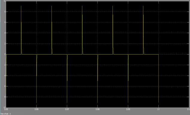
4 Results: 1. R= 500 ohm 5. R= 5K 2. R =1 K 3. R= 2 K 6. R = 20 K 4. R= 3K 1108
5 Conclusion from simulated results: The theoretical concepts discussed are verified by simulating the above model in MATLAB-SIMULINK. It can be seen from the simulated results, that as value of resistance R increases, the curves become steeper i.e the time constant decreases. It means that zero inductor voltage is achieved at a much faster rate with higher resistance values. The results are more explicit when we compare R=500 ohm and R= 20K ohm values. Technical Report TCU/CS/95/17, City University Computer Science Department, London 5. Network Analysis, M.E. Valkenburg, Prentice Hall Inc, References 1.Nilsson J.W., and Riedel S.A., Introduction to PSPICE, Addison-Wesley Publishing Company Inc., Staudhammer John, Circuit Analysis by Digital Computer Prentice-Hall Inc., Seshu S., and Balabanian N., Linear Network Analysis, John Wiley & Sons, Inc., New York, Shankar A., Gilbert D., Jampel M., Transient Analysis of Linear Circuits using Constraint Logic Programming, 1109
Handout 10: Inductance. Self-Inductance and inductors
 1 Handout 10: Inductance Self-Inductance and inductors In Fig. 1, electric current is present in an isolate circuit, setting up magnetic field that causes a magnetic flux through the circuit itself. This
Electrical Circuits (2)
") Electrical Circuits (2) Lecture 7 Transient Analysis Dr.Eng. Basem ElHalawany Extra Reference for this Lecture Chapter 16 Schaum's Outline Of Theory And Problems Of Electric Circuits https://archive.org/details/theoryandproblemsofelectriccircuits
Electrical Circuits (2) Lecture 7 Transient Analysis Dr.Eng. Basem ElHalawany Extra Reference for this Lecture Chapter 16 Schaum's Outline Of Theory And Problems Of Electric Circuits https://archive.org/details/theoryandproblemsofelectriccircuits
Lecture 39. PHYC 161 Fall 2016
 Lecture 39 PHYC 161 Fall 016 Announcements DO THE ONLINE COURSE EVALUATIONS - response so far is < 8 % Magnetic field energy A resistor is a device in which energy is irrecoverably dissipated. By contrast,
MODULE I. Transient Response:
 Transient Response: MODULE I The Transient Response (also known as the Natural Response) is the way the circuit responds to energies stored in storage elements, such as capacitors and inductors. If a capacitor
Inductance, Inductors, RL Circuits & RC Circuits, LC, and RLC Circuits
 Inductance, Inductors, RL Circuits & RC Circuits, LC, and RLC Circuits Self-inductance A time-varying current in a circuit produces an induced emf opposing the emf that initially set up the timevarying
I(t) R L. RL Circuit: Fundamentals. a b. Specifications: E (emf) R (resistance) L (inductance) Switch S: a: current buildup. b: current shutdown
 R L. RL Circuit: Fundamentals. a b. Specifications: E (emf) R (resistance) L (inductance) Switch S: a: current buildup. b: current shutdown") RL Circuit: Fundamentals pecifications: E (emf) R (resistance) L (inductance) witch : a: current buildup a b I(t) R L b: current shutdown Time-dependent quantities: I(t): instantaneous current through
RL Circuit: Fundamentals pecifications: E (emf) R (resistance) L (inductance) witch : a: current buildup a b I(t) R L b: current shutdown Time-dependent quantities: I(t): instantaneous current through
Chapter 32. Inductance
 Chapter 32 Inductance Joseph Henry 1797 1878 American physicist First director of the Smithsonian Improved design of electromagnet Constructed one of the first motors Discovered self-inductance Unit of
Self-inductance A time-varying current in a circuit produces an induced emf opposing the emf that initially set up the time-varying current.
 Inductance Self-inductance A time-varying current in a circuit produces an induced emf opposing the emf that initially set up the time-varying current. Basis of the electrical circuit element called an
Inductance, RL and RLC Circuits
 Inductance, RL and RLC Circuits Inductance Temporarily storage of energy by the magnetic field When the switch is closed, the current does not immediately reach its maximum value. Faraday s law of electromagnetic
Chapter 30 Inductance
 Chapter 30 Inductance In this chapter we investigate the properties of an inductor in a circuit. There are two kinds of inductance mutual inductance and self-inductance. An inductor is formed by taken
What happens when things change. Transient current and voltage relationships in a simple resistive circuit.
 Module 4 AC Theory What happens when things change. What you'll learn in Module 4. 4.1 Resistors in DC Circuits Transient events in DC circuits. The difference between Ideal and Practical circuits Transient
Chapter 32. Inductance
 Chapter 32 Inductance Inductance Self-inductance A time-varying current in a circuit produces an induced emf opposing the emf that initially set up the time-varying current. Basis of the electrical circuit
EE292: Fundamentals of ECE
 EE292: Fundamentals of ECE Fall 2012 TTh 10:00-11:15 SEB 1242 Lecture 14 121011 http://www.ee.unlv.edu/~b1morris/ee292/ 2 Outline Review Steady-State Analysis RC Circuits RL Circuits 3 DC Steady-State
Assessment Schedule 2015 Physics: Demonstrate understanding of electrical systems (91526)
") NCEA Level 3 Physics (91526) 2015 page 1 of 6 Assessment Schedule 2015 Physics: Demonstrate understanding of electrical systems (91526) Evidence Q Evidence Achievement Achievement with Merit Achievement
NCEA Level 3 Physics (91526) 2015 page 1 of 6 Assessment Schedule 2015 Physics: Demonstrate understanding of electrical systems (91526) Evidence Q Evidence Achievement Achievement with Merit Achievement
First Order RC and RL Transient Circuits
 First Order R and RL Transient ircuits Objectives To introduce the transients phenomena. To analyze step and natural responses of first order R circuits. To analyze step and natural responses of first
Slide 1 / 26. Inductance by Bryan Pflueger
 Slide 1 / 26 Inductance 2011 by Bryan Pflueger Slide 2 / 26 Mutual Inductance If two coils of wire are placed near each other and have a current passing through them, they will each induce an emf on one
Electromagnetic Induction & Inductors
 Electromagnetic Induction & Inductors 1 Revision of Electromagnetic Induction and Inductors (Much of this material has come from Electrical & Electronic Principles & Technology by John Bird) Magnetic Field
Chapter 30. Inductance. PowerPoint Lectures for University Physics, 14th Edition Hugh D. Young and Roger A. Freedman Lectures by Jason Harlow
 Chapter 30 Inductance PowerPoint Lectures for University Physics, 14th Edition Hugh D. Young and Roger A. Freedman Lectures by Jason Harlow Learning Goals for Chapter 30 Looking forward at how a time-varying
David J. Starling Penn State Hazleton PHYS 212
 and and The term inductance was coined by Oliver Heaviside in February 1886. David J. Starling Penn State Hazleton PHYS 212 and We have seen electric flux: Φ E = E d A But we can define the magnetic flux
Electromagnetic Induction (Chapters 31-32)
") Electromagnetic Induction (Chapters 31-3) The laws of emf induction: Faraday s and Lenz s laws Inductance Mutual inductance M Self inductance L. Inductors Magnetic field energy Simple inductive circuits
Electromagnetic Induction (Chapters 31-3) The laws of emf induction: Faraday s and Lenz s laws Inductance Mutual inductance M Self inductance L. Inductors Magnetic field energy Simple inductive circuits
Active Figure 32.3 (SLIDESHOW MODE ONLY)
") RL Circuit, Analysis An RL circuit contains an inductor and a resistor When the switch is closed (at time t = 0), the current begins to increase At the same time, a back emf is induced in the inductor
RL Circuit, Analysis An RL circuit contains an inductor and a resistor When the switch is closed (at time t = 0), the current begins to increase At the same time, a back emf is induced in the inductor
2005 AP PHYSICS C: ELECTRICITY AND MAGNETISM FREE-RESPONSE QUESTIONS
 2005 AP PHYSICS C: ELECTRICITY AND MAGNETISM In the circuit shown above, resistors 1 and 2 of resistance R 1 and R 2, respectively, and an inductor of inductance L are connected to a battery of emf e and
PHYS 1441 Section 001 Lecture #23 Monday, Dec. 4, 2017
 PHYS 1441 Section 1 Lecture #3 Monday, Dec. 4, 17 Chapter 3: Inductance Mutual and Self Inductance Energy Stored in Magnetic Field Alternating Current and AC Circuits AC Circuit W/ LRC Chapter 31: Maxwell
Electromagnetic Induction Faraday s Law Lenz s Law Self-Inductance RL Circuits Energy in a Magnetic Field Mutual Inductance
 Lesson 7 Electromagnetic Induction Faraday s Law Lenz s Law Self-Inductance RL Circuits Energy in a Magnetic Field Mutual Inductance Oscillations in an LC Circuit The RLC Circuit Alternating Current Electromagnetic
Chapter 30 Inductance and Electromagnetic Oscillations
 Chapter 30 Inductance and Electromagnetic Oscillations Units of Chapter 30 30.1 Mutual Inductance: 1 30.2 Self-Inductance: 2, 3, & 4 30.3 Energy Stored in a Magnetic Field: 5, 6, & 7 30.4 LR Circuit: 8,
EXPERIMENT 07 TO STUDY DC RC CIRCUIT AND TRANSIENT PHENOMENA
 EXPERIMENT 07 TO STUDY DC RC CIRCUIT AND TRANSIENT PHENOMENA DISCUSSION The capacitor is a element which stores electric energy by charging the charge on it. Bear in mind that the charge on a capacitor
Chapter 2. Engr228 Circuit Analysis. Dr Curtis Nelson
 Chapter 2 Engr228 Circuit Analysis Dr Curtis Nelson Chapter 2 Objectives Understand symbols and behavior of the following circuit elements: Independent voltage and current sources; Dependent voltage and
2006 #3 10. a. On the diagram of the loop below, indicate the directions of the magnetic forces, if any, that act on each side of the loop.
 1992 1 1994 2 3 3 1984 4 1991 5 1987 6 1980 8 7 9 2006 #3 10 1985 2006E3. A loop of wire of width w and height h contains a switch and a battery and is connected to a spring of force constant k, as shown
Chapter 28. Direct Current Circuits
 Chapter 28 Direct Current Circuits Circuit Analysis Simple electric circuits may contain batteries, resistors, and capacitors in various combinations. For some circuits, analysis may consist of combining
EECE251. Circuit Analysis I. Set 4: Capacitors, Inductors, and First-Order Linear Circuits
 EECE25 Circuit Analysis I Set 4: Capacitors, Inductors, and First-Order Linear Circuits Shahriar Mirabbasi Department of Electrical and Computer Engineering University of British Columbia shahriar@ece.ubc.ca
PHYS 202 Notes, Week 6
 PHYS 202 Notes, Week 6 Greg Christian February 23 & 25, 2016 Last updated: 02/25/2016 at 12:36:40 This week we learn about electromagnetic induction. Magnetic Induction This section deals with magnetic
Chapter 21 Magnetic Induction Lecture 12
 Chapter 21 Magnetic Induction Lecture 12 21.1 Why is it called Electromagnetism? 21.2 Magnetic Flux and Faraday s Law 21.3 Lenz s Law and Work-Energy Principles 21.4 Inductance 21.5 RL Circuits 21.6 Energy
Induction and Inductance
 Induction and Inductance Key Contents Faraday s law: induced emf Induction and energy transfer Inductors and inductance RL circuits Magnetic energy density The First Experiment 1. A current appears only
Chapter 30 Self Inductance, Inductors & DC Circuits Revisited
 Chapter 30 Self Inductance, Inductors & DC Circuits Revisited Self-Inductance and Inductors Self inductance determines the magnetic flux in a circuit due to the circuit s own current. B = LI Every circuit
Lecture 27: FRI 20 MAR
 Physics 2102 Jonathan Dowling Lecture 27: FRI 20 MAR Ch.30.7 9 Inductors & Inductance Nikolai Tesla Inductors: Solenoids Inductors are with respect to the magnetic field what capacitors are with respect
ELECTROMAGNETIC INDUCTION AND FARADAY S LAW
 ELECTROMAGNETIC INDUCTION AND FARADAY S LAW Magnetic Flux The emf is actually induced by a change in the quantity called the magnetic flux rather than simply py by a change in the magnetic field Magnetic
Assessment Schedule 2016 Physics: Demonstrate understanding electrical systems (91526)
") NCEA evel 3 Physics (91526) 2016 page 1 of 5 Assessment Schedule 2016 Physics: Demonstrate understanding electrical systems (91526) Evidence Statement NØ N1 N 2 A 3 A 4 M 5 M 6 E 7 E 8 0 1A 2A 3A 4A or
NCEA evel 3 Physics (91526) 2016 page 1 of 5 Assessment Schedule 2016 Physics: Demonstrate understanding electrical systems (91526) Evidence Statement NØ N1 N 2 A 3 A 4 M 5 M 6 E 7 E 8 0 1A 2A 3A 4A or
AP Physics C. Inductance. Free Response Problems
 AP Physics C Inductance Free Response Problems 1. Two toroidal solenoids are wounded around the same frame. Solenoid 1 has 800 turns and solenoid 2 has 500 turns. When the current 7.23 A flows through
Chapters 34,36: Electromagnetic Induction. PHY2061: Chapter
 Chapters 34,36: Electromagnetic Induction PHY2061: Chapter 34-35 1 Electromagnetic Induction Magnetic flux Induced emf Faraday s Law Lenz s Law Motional emf Magnetic energy Inductance RL circuits Generators
INDUCTANCE Self Inductance
 NDUTANE 3. Self nductance onsider the circuit shown in the Figure. When the switch is closed the current, and so the magnetic field, through the circuit increases from zero to a specific value. The increasing
Inductive & Capacitive Circuits. Subhasish Chandra Assistant Professor Department of Physics Institute of Forensic Science, Nagpur
 Inductive & Capacitive Circuits Subhasish Chandra Assistant Professor Department of Physics Institute of Forensic Science, Nagpur LR Circuit LR Circuit (Charging) Let us consider a circuit having an inductance
PHYSICS. Chapter 30 Lecture FOR SCIENTISTS AND ENGINEERS A STRATEGIC APPROACH 4/E RANDALL D. KNIGHT
 PHYSICS FOR SCIENTISTS AND ENGINEERS A STRATEGIC APPROACH 4/E Chapter 30 Lecture RANDALL D. KNIGHT Chapter 30 Electromagnetic Induction IN THIS CHAPTER, you will learn what electromagnetic induction is
Chapter 30 INDUCTANCE. Copyright 2012 Pearson Education Inc.
 Chapter 30 INDUCTANCE Goals for Chapter 30 To learn how current in one coil can induce an emf in another unconnected coil To relate the induced emf to the rate of change of the current To calculate the
Electromagnetic Oscillations and Alternating Current. 1. Electromagnetic oscillations and LC circuit 2. Alternating Current 3.
 Electromagnetic Oscillations and Alternating Current 1. Electromagnetic oscillations and LC circuit 2. Alternating Current 3. RLC circuit in AC 1 RL and RC circuits RL RC Charging Discharging I = emf R
Version 001 CIRCUITS holland (1290) 1
 1") Version CIRCUITS holland (9) This print-out should have questions Multiple-choice questions may continue on the next column or page find all choices before answering AP M 99 MC points The power dissipated
Version CIRCUITS holland (9) This print-out should have questions Multiple-choice questions may continue on the next column or page find all choices before answering AP M 99 MC points The power dissipated
EM Oscillations. David J. Starling Penn State Hazleton PHYS 212
 I ve got an oscillating fan at my house. The fan goes back and forth. It looks like the fan is saying No. So I like to ask it questions that a fan would say no to. Do you keep my hair in place? Do you
Inductance. Slide 2 / 26. Slide 1 / 26. Slide 4 / 26. Slide 3 / 26. Slide 6 / 26. Slide 5 / 26. Mutual Inductance. Mutual Inductance.
 Slide 1 / 26 Inductance 2011 by Bryan Pflueger Slide 2 / 26 Mutual Inductance If two coils of wire are placed near each other and have a current passing through them, they will each induce an emf on one
ELECTROMAGNETIC OSCILLATIONS AND ALTERNATING CURRENT
 Chapter 31: ELECTROMAGNETIC OSCILLATIONS AND ALTERNATING CURRENT 1 A charged capacitor and an inductor are connected in series At time t = 0 the current is zero, but the capacitor is charged If T is the
PHYSICS 171. Experiment 3. Kirchhoff's Laws. Three resistors (Nominally: 1 Kilohm, 2 Kilohm, 3 Kilohm).
.") PHYSICS 171 Experiment 3 Kirchhoff's Laws Equipment: Supplies: Digital Multimeter, Power Supply (0-20 V.). Three resistors (Nominally: 1 Kilohm, 2 Kilohm, 3 Kilohm). A. Kirchhoff's Loop Law Suppose that
PHYSICS 171 Experiment 3 Kirchhoff's Laws Equipment: Supplies: Digital Multimeter, Power Supply (0-20 V.). Three resistors (Nominally: 1 Kilohm, 2 Kilohm, 3 Kilohm). A. Kirchhoff's Loop Law Suppose that
DO PHYSICS ONLINE MOTORS AND GENERATORS FARADAY S LAW ELECTROMAGNETIC INDUCTION
 DO PHYSICS ONLINE MOTORS AND GENERATORS FARADAY S LAW ELECTROMAGNETIC INDUCTION English Michael Faraday (1791 1867) who experimented with electric and magnetic phenomena discovered that a changing magnetic
Physics 2112 Unit 18
 Physics 2112 Unit 18 Today s Concepts: A) Induction B) Circuits Electricity & Magnetism ecture 18, Slide 1 Where we are.. Just finished introducing magnetism Will now apply magnetism to AC circuits Unit
 Alternating Currents. The power is transmitted from a power house on high voltage ac because (a) Electric current travels faster at higher volts (b) It is more economical due to less power wastage (c)
Chapter 20: Electromagnetic Induction. PHY2054: Chapter 20 1
 Chapter 20: Electromagnetic Induction PHY2054: Chapter 20 1 Electromagnetic Induction Magnetic flux Induced emf Faraday s Law Lenz s Law Motional emf Magnetic energy Inductance RL circuits Generators and
Electricity & Magnetism
 Electricity & Magnetism D.C. Circuits Marline Kurishingal Note : This chapter includes only D.C. In AS syllabus A.C is not included. Recap... Electrical Circuit Symbols : Draw and interpret circuit diagrams
Inductance and Magnetic Energy
 Mutual Inductance Inductance and Magnetic Energy Consider two wire loops or coils. Their geometries can be completely general, and there might be some magnetic materials inside the coils or around them
Electromotive Force. The electromotive force (emf), ε, of a battery is the maximum possible voltage that the battery can provide between its terminals
, ε, of a battery is the maximum possible voltage that the battery can provide between its terminals") Direct Current When the current in a circuit has a constant magnitude and direction, the current is called direct current Because the potential difference between the terminals of a battery is constant,
Direct Current When the current in a circuit has a constant magnitude and direction, the current is called direct current Because the potential difference between the terminals of a battery is constant,
Inductance, RL Circuits, LC Circuits, RLC Circuits
 Inductance, R Circuits, C Circuits, RC Circuits Inductance What happens when we close the switch? The current flows What does the current look like as a function of time? Does it look like this? I t Inductance
Alternating Current Circuits
 Alternating Current Circuits AC Circuit An AC circuit consists of a combination of circuit elements and an AC generator or source. The output of an AC generator is sinusoidal and varies with time according
ELECTRONICS E # 1 FUNDAMENTALS 2/2/2011
 FE Review 1 ELECTRONICS E # 1 FUNDAMENTALS Electric Charge 2 In an electric circuit it there is a conservation of charge. The net electric charge is constant. There are positive and negative charges. Like
Experiment Guide for RC Circuits
 Guide-P1 Experiment Guide for RC Circuits I. Introduction 1. Capacitors A capacitor is a passive electronic component that stores energy in the form of an electrostatic field. The unit of capacitance is
Induction and Inductance
 Welcome Back to Physics 1308 Induction and Inductance Heinrich Friedrich Emil Lenz 12 February 1804 10 February 1865 Announcements Assignments for Thursday, November 8th: - Reading: Chapter 33.1 - Watch
Circuit Analysis-II. Circuit Analysis-II Lecture # 5 Monday 23 rd April, 18
 Circuit Analysis-II Capacitors in AC Circuits Introduction ü The instantaneous capacitor current is equal to the capacitance times the instantaneous rate of change of the voltage across the capacitor.
Physics 2020 Exam 2 Constants and Formulae
 Physics 2020 Exam 2 Constants and Formulae Useful Constants k e = 8.99 10 9 N m 2 /C 2 c = 3.00 10 8 m/s ɛ = 8.85 10 12 C 2 /(N m 2 ) µ = 4π 10 7 T m/a e = 1.602 10 19 C h = 6.626 10 34 J s m p = 1.67
iclicker: which statements are correct?
 iclicker: which statements are correct? 1. Electric field lines must originate and terminate on charges 2. Magnetic field lines are always closed A: 1&2 B: only 1 C: only 2 D: neither 2 Inductive E-field:
Last time. Ampere's Law Faraday s law
 Last time Ampere's Law Faraday s law 1 Faraday s Law of Induction (More Quantitative) The magnitude of the induced EMF in conducting loop is equal to the rate at which the magnetic flux through the surface
Physics 1c Practical, Spring 2015 Hw 3 Solutions
 Physics 1c Practical, Spring 2015 Hw 3 Solutions April 16, 2015 1 Serway 31.79 (5 points) By Lenz s Law, current will flow in each of the two sub-loops to oppose the change in flux. One can easily see
 Superconductors A class of materials and compounds whose resistances fall to virtually zero below a certain temperature, T C T C is called the critical temperature The graph is the same as a normal metal
PRACTICE EXAM 1 for Midterm 2
 PRACTICE EXAM 1 for Midterm 2 Multiple Choice Questions 1) The figure shows three identical lightbulbs connected to a battery having a constant voltage across its terminals. What happens to the brightness
Electricity and Magnetism Energy of the Magnetic Field Mutual Inductance
 Electricity and Magnetism Energy of the Magnetic Field Mutual Inductance Lana Sheridan De Anza College Mar 14, 2018 Last time inductors resistor-inductor circuits Overview wrap up resistor-inductor circuits
Ch. 23 Electromagnetic Induction, AC Circuits, And Electrical Technologies
 Ch. 23 Electromagnetic Induction, AC Circuits, And Electrical Technologies Induced emf - Faraday s Experiment When a magnet moves toward a loop of wire, the ammeter shows the presence of a current When
This work is licensed under a Creative Commons Attribution-Noncommercial-Share Alike 4.0 License.
 University of Rhode Island DigitalCommons@URI PHY 204: Elementary Physics II Physics Course Materials 2015 18. RL Circuits Gerhard Müller University of Rhode Island, gmuller@uri.edu Creative Commons License
First-order transient
 EIE209 Basic Electronics First-order transient Contents Inductor and capacitor Simple RC and RL circuits Transient solutions Constitutive relation An electrical element is defined by its relationship between
Final on December Physics 106 R. Schad. 3e 4e 5c 6d 7c 8d 9b 10e 11d 12e 13d 14d 15b 16d 17b 18b 19c 20a
 Final on December11. 2007 - Physics 106 R. Schad YOUR NAME STUDENT NUMBER 3e 4e 5c 6d 7c 8d 9b 10e 11d 12e 13d 14d 15b 16d 17b 18b 19c 20a 1. 2. 3. 4. This is to identify the exam version you have IMPORTANT
Self-Inductance. Φ i. Self-induction. = (if flux Φ 1 through 1 loop. Tm Vs A A. Lecture 11-1
 Lecture - Self-Inductance As current i through coil increases, magnetic flux through itself increases. This in turn induces back emf in the coil itself When current i is decreasing, emf is induced again
Magnetic Induction Faraday, Lenz, Mutual & Self Inductance Maxwell s Eqns, E-M waves. Reading Journals for Tuesday from table(s)
") PHYS 2015 -- Week 12 Magnetic Induction Faraday, Lenz, Mutual & Self Inductance Maxwell s Eqns, E-M waves Reading Journals for Tuesday from table(s) WebAssign due Friday night For exclusive use in PHYS
PHYS 2015 -- Week 12 Magnetic Induction Faraday, Lenz, Mutual & Self Inductance Maxwell s Eqns, E-M waves Reading Journals for Tuesday from table(s) WebAssign due Friday night For exclusive use in PHYS
Electricity & Magnetism Lecture 18
 Electricity & Magnetism ecture 18 Today s Concepts: A) Induc4on B) R Circuits Electricity & Magne4sm ecture 18, Slide 1 Stuff you said.. Will there be more lab ac4vi4es involving oscilloscopes? Unlike
1 Fig. 3.1 shows the variation of the magnetic flux linkage with time t for a small generator. magnetic. flux linkage / Wb-turns 1.
 1 Fig. 3.1 shows the variation of the magnetic flux linkage with time t for a small generator. 2 magnetic 1 flux linkage / 0 10 2 Wb-turns 1 2 5 10 15 t / 10 3 s Fig. 3.1 The generator has a flat coil
Chapter 26 & 27. Electric Current and Direct- Current Circuits
 Chapter 26 & 27 Electric Current and Direct- Current Circuits Electric Current and Direct- Current Circuits Current and Motion of Charges Resistance and Ohm s Law Energy in Electric Circuits Combination
Lecture 24. April 5 th, Magnetic Circuits & Inductance
 Lecture 24 April 5 th, 2005 Magnetic Circuits & Inductance Reading: Boylestad s Circuit Analysis, 3 rd Canadian Edition Chapter 11.1-11.5, Pages 331-338 Chapter 12.1-12.4, Pages 341-349 Chapter 12.7-12.9,
ε induced Review: Self-inductance 20.7 RL Circuits Review: Self-inductance B induced Announcements
 Announcements WebAssign HW Set 7 due this Friday Problems cover material from Chapters 20 and 21 We re skipping Sections 21.1-21.7 (alternating current circuits) Review: Self-inductance induced ε induced
Source-Free RC Circuit
 First Order Circuits Source-Free RC Circuit Initial charge on capacitor q = Cv(0) so that voltage at time 0 is v(0). What is v(t)? Prof Carruthers (ECE @ BU) EK307 Notes Summer 2018 150 / 264 First Order
Introduction to AC Circuits (Capacitors and Inductors)
") Introduction to AC Circuits (Capacitors and Inductors) Amin Electronics and Electrical Communications Engineering Department (EECE) Cairo University elc.n102.eng@gmail.com http://scholar.cu.edu.eg/refky/
Introduction to AC Circuits (Capacitors and Inductors) Amin Electronics and Electrical Communications Engineering Department (EECE) Cairo University elc.n102.eng@gmail.com http://scholar.cu.edu.eg/refky/
Induction and inductance
 PH -C Fall 01 Induction and inductance Lecture 15 Chapter 30 (Halliday/Resnick/Walker, Fundamentals of Physics 8 th etion) 1 Chapter 30 Induction and Inductance In this chapter we will study the following
Chapter 23 Magnetic Flux and Faraday s Law of Induction
 Chapter 23 Magnetic Flux and Faraday s Law of Induction 1 Overview of Chapter 23 Induced Electromotive Force Magnetic Flux Faraday s Law of Induction Lenz s Law Mechanical Work and Electrical Energy Generators
Physics 240 Fall 2005: Exam #3 Solutions. Please print your name: Please list your discussion section number: Please list your discussion instructor:
 Physics 4 Fall 5: Exam #3 Solutions Please print your name: Please list your discussion section number: Please list your discussion instructor: Form #1 Instructions 1. Fill in your name above. This will
Direct-Current Circuits
 Direct-Current Circuits A'.3/.". 39 '- )232.-/ 32,+/" 7+3(5-.)232.-/ 7 3244)'03,.5B )*+,"- &'&./( 0-1*234 35-2567+- *7 2829*4-& )"< 35- )*+,"-= 9-4-- 3563 A0.5.C2/'-231).D')232.')2-1 < /633-">&@5-:836+-0"1464-625"-4*43"
Introduction to Electric Circuit Analysis
 EE110300 Practice of Electrical and Computer Engineering Lecture 2 and Lecture 4.1 Introduction to Electric Circuit Analysis Prof. Klaus Yung-Jane Hsu 2003/2/20 What Is An Electric Circuit? Electrical
Mansfield Independent School District AP Physics C: Electricity and Magnetism Year at a Glance
 Mansfield Independent School District AP Physics C: Electricity and Magnetism Year at a Glance First Six-Weeks Second Six-Weeks Third Six-Weeks Lab safety Lab practices and ethical practices Math and Calculus
Note 11: Alternating Current (AC) Circuits
 Circuits") Note 11: Alternating Current (AC) Circuits V R No phase difference between the voltage difference and the current and max For alternating voltage Vmax sin t, the resistor current is ir sin t. the instantaneous
Note 11: Alternating Current (AC) Circuits V R No phase difference between the voltage difference and the current and max For alternating voltage Vmax sin t, the resistor current is ir sin t. the instantaneous
K2-04: FARADAY'S EXPERIMENT - EME K2-43: LENZ'S LAW - PERMANENT MAGNET AND COILS
 K2-04: FARADAY'S EXPERIMENT - EME SET - 20, 40, 80 TURN COILS K2-62: CAN SMASHER - ELECTROMAGNETIC K2-43: LENZ'S LAW - PERMANENT MAGNET AND COILS K2-44: EDDY CURRENT PENDULUM K4-06: MAGNETOELECTRIC GENERATOR
LECTURE 8 RC AND RL FIRST-ORDER CIRCUITS (PART 1)
") CIRCUITS by Ulaby & Maharbiz LECTURE 8 RC AND RL FIRST-ORDER CIRCUITS (PART 1) 07/18/2013 ECE225 CIRCUIT ANALYSIS All rights reserved. Do not copy or distribute. 2013 National Technology and Science Press
CIRCUITS by Ulaby & Maharbiz LECTURE 8 RC AND RL FIRST-ORDER CIRCUITS (PART 1) 07/18/2013 ECE225 CIRCUIT ANALYSIS All rights reserved. Do not copy or distribute. 2013 National Technology and Science Press
IE1206 Embedded Electronics Le2
 Le1 Le3 Le4 Le6 Le8 IE1206 Embedded Electronics Le2 Ex1 Ex2 Ex4 Ex5 PIC-block Documentation, Seriecom Pulse sensors I, U, R, P, serial and parallel KC1 LAB1 Pulse sensors, Menu program Kirchhoffs laws
Electric Circuits Fall 2015 Solution #5
 RULES: Please try to work on your own. Discussion is permissible, but identical submissions are unacceptable! Please show all intermeate steps: a correct solution without an explanation will get zero cret.
AP Physics C. Magnetism - Term 4
 AP Physics C Magnetism - Term 4 Interest Packet Term Introduction: AP Physics has been specifically designed to build on physics knowledge previously acquired for a more in depth understanding of the world
Electrical Engineering Fundamentals for Non-Electrical Engineers
 Electrical Engineering Fundamentals for Non-Electrical Engineers by Brad Meyer, PE Contents Introduction... 3 Definitions... 3 Power Sources... 4 Series vs. Parallel... 9 Current Behavior at a Node...
r where the electric constant
 1.0 ELECTROSTATICS At the end of this topic, students will be able to: 10 1.1 Coulomb s law a) Explain the concepts of electrons, protons, charged objects, charged up, gaining charge, losing charge, charging
Applications of Second-Order Differential Equations
 Applications of Second-Order Differential Equations ymy/013 Building Intuition Even though there are an infinite number of differential equations, they all share common characteristics that allow intuition
General Physics (PHY 2140)
") General Physics (PHY 2140) Lecture 10 6/12/2007 Electricity and Magnetism Induced voltages and induction Self-Inductance RL Circuits Energy in magnetic fields AC circuits and EM waves Resistors, capacitors
General Physics (PHY 2140) Lecture 10 6/12/2007 Electricity and Magnetism Induced voltages and induction Self-Inductance RL Circuits Energy in magnetic fields AC circuits and EM waves Resistors, capacitors
ELEC ELE TRO TR MAGNETIC INDUCTION
 ELECTRO MAGNETIC INDUCTION Faraday Henry 1791-1867 1797 1878 Laws:- Faraday s Laws :- 1) When ever there is a change in magnetic flux linked with a coil, a current is generated in the coil. The current
RC, RL, and LCR Circuits
 RC, RL, and LCR Circuits EK307 Lab Note: This is a two week lab. Most students complete part A in week one and part B in week two. Introduction: Inductors and capacitors are energy storage devices. They