Failure Mode Predictions in the Compressive Response of Laminated Composites
|
|
|
- Dwight Copeland
- 6 years ago
- Views:
Transcription
1 Structures, Structural Dynamics, and Materials and Co-located Conferences April 8-11, 2013, Boston, Massachusetts 54th AIAA/ASME/ASCE/AHS/ASC Structures, Structural Dynamics, and Materials Conference AIAA Failure Mode Predictions in the Compressive Response of Laminated Composites Pavana Prabhakar and Anthony M Waas Of interest in this paper are failure mode interactions when laminated fiber reinforced composites are subjected to compressive loading. Delamination, fiber kink-banding and their interactions are seen to dominate the failure response. This interaction is captured through a computational model that includes interface elements to capture delamination, and, geometric and material nonlinearity to capture kink banding. A 2D cross-section analysis is used to guide the choice of interfaces that require cohesive elements, thus reducing computational complexity. Two different stacking sequences are investigated, and their compressive strength and failure modes are compared, between prediction and experiments. I. Introduction Fiber kink banding has been identified as a compressive strength limiting mechanism in aligned fiber reinforced composite laminates that are finding increasing use in lightweight aero-structures (Schultheisz and Waas, 1 Waas and Schultheisz 2 ). While early studies determined that the compressive strength can be determined by a knowledge of the shear nonlinearity in the stress-strain response of a lamina in tandem with a knowledge of initial fiber misalignment, 3, 4 it was later determined through a combination of experiments and numerical modeling that the kink band formation is an evolutionary process, leading to deformation localization. The mechanism is governed by local stress state (including stress multi-axiality), details of the material constitutive model and the fiber misalignment angles as explained in papers by Sun and Jun, 5 Kyriakides et al., 6 Lee and Waas, 7 Vogler et al., 8 Yerramalli and Waas, 9 Yerramalli and Waas, 10 Basu et al., 11 Pimenta et al., 12, 13 Feld et al. 14 As loading proceeds, regions of fiber misalignment in the composite undergo deformation due to combined compression and shear loading. This region is surrounded by other material whose deformation characteristics, in general, are different. The progressively increasing local fiber misalignment coupled with a softening shear nonlinearity, perpetuates a local limit-load type instability that initiates a rapid formation of a kink band. During this formation, the external tractions required to support the structure, in general, decrease, indicating an instability. The regions within the band undergo large straining while material outside the band, relax and unload. Consequently, the mechanics of this process is related to the local microstructural details, geometry and volumes of material that are occupied by the band and that which are outside the band. Lee and Waas, 7 Lee et al., 15 Vogler et al. 8 and Pimenta et al., 12, 13 have shown that kink-band formation can also involve delamination (splitting) in combination or in isolation of the band formation. Lee and Waas 7 studied the effect of fiber volume fraction on the compression failure mode, while Yerramalli and Waas 9 studied the effect of fiber type and load multi-axiality on failure. The formation of kink banding as an energy release mechanism in limiting the compressive strength of laminates with cut-outs has previously been addressed by Waas et al., 16 Ahn and Waas, 17, 18 and Berbinau et al., 19 while the influence of fiber waviness on compression failure of unidirectional laminates has been studied by Wisnom. 20 Micromechanical models to predict compressive strength using varying degrees of simplification have been proposed by Naik and Kumar, 21 and, Xu and Reifsnider. 22 While kink banding is governed by the inelastic response of the matrix material in a misaligned fiber composite, delamination is governed by the fracture properties of the matrix and/or fiber matrix interface,. 23 Graduate Student, Department of Aerospace Engineering, 1320 Beal Avenue, Ann Arbor, MI AIAA Student Member. Felix Pawlowski Professor of Aerospace Engineering, Department of Aerospace Engineering, 1320 Beal Avenue, Ann Arbor, MI Fellow, AIAA. 1 of 15 Copyright 2013 by Pavana Prabhakar. Published by the, Inc., with permission.
2 In this paper, multi-directional carbon fiber reinforced polymer (CFRP) matrix laminates are considered. The main goal of this paper is to develop a procedure to predict compressive strength and failure modes in multi-directional laminates. In this regard, a semi-homogenized laminate model is constructed, where micro-mechanics is maintained in the 0 degree fibers and the off-axis layers are homogenized. Further, to predict the compressive strength and failure modes, cohesive elements are added at chosen interfaces of the model to incorporate the ability to delaminate. These interfaces are determined a priori by a simplified 2-D analysis of the laminate. The compressive strength and failure modes are predicted for two laminates with different stacking sequence, and compared against experimental observations and test data. Two types of laminates with different stacking sequence are studied here. The first type of laminate, namely, Type A laminates, have a stacking sequence of [ 45/ + 45/90/0]s, [ 45 2 / /90 2 /0 2 ]s and [ 45 4 / /90 4 /0 4 ]s with totals of 8, 16 and 32 layers, respectively. The second laminate is referred to as Type B laminate, with a stacking sequence of [( 45/+45/90/0) 6 ]s, with 48 layers. It should be noted that the zero degree layers are grouped together along the centerline in Type A laminate, whereas they are distributed in the Type B laminate. Upscaled homogenized laminate models are constructed for both types of laminates using the upscaled semi-homogenized modeling method explained in Prabhakar and Waas. 24 In these models, each 0 degree lamina has hexagonally packed fibers maintaining the micro-mechanics, and the off-axis layers are homogenized using a deformation theory implementation of Hill s anisotropic plasticity theory. Interface elements formulated using the discrete cohesive zone method (DCZM) (Gustafson and Waas 25 ), are added at the critical interfaces which are determined a-priori as the delamination prone interfaces in the laminate, via a simplified 2-D analysis of the laminate. Finally, the laminate model is subjected to compression in the axial direction, using displacement control, to predict the compressive strength and failure modes. II. A. Type of Laminates Investigated Experimental Observations The two types of laminates investigated are shown in Fig. 1(a) and Fig. 1(c). Different layers are seen in the figures through contrasting colors in the images. The Type A laminate shown in Fig. 1(a) contains 16 layers, and the Type B laminate in Fig. 1(c) contains 48 layers. Both laminates are symmetric about the centerline. B. Compression Test Fixture and Specimens Compression tests were conducted on Type A and Type B laminates to understand the mechanisms of failure that are unique to the different type of laminates. The influence of two important types of failure mechanisms, namely delamination and kinking, and their interaction on the compression strength is the main focus. In the following sections, details about the experimental set-up, stacking sequences (also referred to as layups) of different specimens and results of the compression experiments are presented. The Wyoming Combined Loading Compression (WCLC) test fixture was used to carry out the compressive response studies in association with a MTS loading frame. Specimens in the form of strips of laminates with nominal dimensions of 12.7 mm x mm x t mm, where, t is variable, are sandwiched between the large metal blocks of the fixture, and the ends of the fixture are compressed between the flat loading platens of a MTS testing frame. The blocks act as anti-buckling guides during loading, supporting a large portion of the specimen length, and providing a length of 6.35 mm as the gage length. This results in the measured compressive strength to be as close as possible to the actual compressive strength of the material, with minimal tendency towards flexural buckling. Specimens of three layups of Type A laminates, with varying thickness, and Type B laminates were tested under compression. The Type A specimens were also used to study the effects of scaling, by grouping families of lamina, on the compressive strength of the laminates. As indicated in Table 1, the thicknesses of the layups are scaled up by stacking multiple layers of the same orientation. All the laminates shown in Table 1 have the same in-plane extensional stiffnesses. All the specimens are of nominal size 12.7 mm x mm which results in a nominal gage length of 6.35 mm when placed in the WCLC fixture. Fig. 1(b) displays the image of a failed Type A 16-ply laminate. It is observed that the failed specimen shows extensive delamination occurring at the interface of the laminae, and kinking in the 0 degree ply. Fig. 1(d) shows a failed Type B specimen. We observe kink band formation in 0 layers, and small delaminated regions around the kink band are observed. There is no extensive delamination observed in Type B laminates 2 of 15
 W(mm) t(mm) Type A (8 plies): [ 45/ + 45/90/0]s 6.35 12.7 1.24 Type A (16 plies): [ 452 / + 452 /902 /02 ]s 6.35 12.7 2.")
![38 Type A (32 plies): [ 454 / + 454 /904 /04 ]s 6.35 12.7 4.47 Type B (48 plies): [( 45/ + 45/90/0)6 ]s 6.35 12.7 6.35 as in the case of Type A laminates. C.](/docs-images/72/66592415/images/3-2.jpg "Compressive Strength Measurements The compressive response studies are carried out at an external displacement control loading rate of 0.0004 in/sec in a MTS hydraulic test frame.")


3 (a) (b) (c) (d) Figure 1. (a) Pristine Type-A laminate; (b) Failed Type-A laminate; (c) Pristine Type-B laminate; (d) Failed Type-B laminate Table 1. Types of laminates Type of Laminates L(mm) W(mm) t(mm) Type A (8 plies): [ 45/ + 45/90/0]s Type A (16 plies): [ 452 / /902 /02 ]s Type A (32 plies): [ 454 / /904 /04 ]s Type B (48 plies): [( 45/ + 45/90/0)6 ]s as in the case of Type A laminates. C. Compressive Strength Measurements The compressive response studies are carried out at an external displacement control loading rate of in/sec in a MTS hydraulic test frame. The macroscopic stress is calculated as the total load obtained from a load cell that is placed in-line with the specimen, divided by the initial undeformed cross sectional area of the specimen. The macroscopic strain is determined using strain gages on either faces of the specimens. The global stress-strain responses of Type A laminates are shown in Fig. 2. The initial stiffness of the laminates is 48.5 ± 2 GPa, and the compressive strengths are in the range of 590 ± 30 MPa. The results imply that the scaling of lamina thickness in the laminate has no significant influence on either the initial stiffness or the strength of the Type A laminates. The Type B laminates displayed a similar trend with an initial stiffness of 49.3 ± 0.5 GPa, and the compressive strengths are in the range of 615 ± 20 MPa. 3 of 15
4 Stress (MPa) Ply:Test Ply:Test 2 16 Ply:Test Ply:Test 2 32 Ply:Test 1 32 Ply:Test Strain Figure 2. Global stress-strain response of the Type A laminates determined experimentally D. Strain Analysis of Laminates Using Digital Image Correlation (DIC) The digital image correlation (DIC) method was used to analyze the strain distribution on the side face of the laminates. ARAMIS, a commercially available software package, is used to perform the DIC analysis. ARAMIS is a non-contact and material independent displacement measuring system that gives displacements, strains and velocities as a function of time. 26 The side surface of the specimen (through the thickness), which is to be imaged, has a speckle pattern with random black dots over a white background, created using an air-brush. The side surface that is imaged is the surface with a normal in the y - direction. A series of images are taken during the experiment, and these images are analyzed using ARAMIS to calculate the displacement and strain fields. The DIC images of the side surface of a typical 16-ply Type A specimen are shown in Fig. 3(a) and Fig. 3(b). The specimen is loaded in the global x-direction. Fig. 3(a) and Fig. 3(b) display the strain distribution on the side face of the specimen along the global z-direction corresponding to a point prior to peak load and at the peak load of the loaded specimen. It can be observed that the distribution is banded along the thickness. This is due to the different layers present in the specimens. We also observe that, as the loading is increased, the positive strain between the layers +45 and -45 increases rapidly, and subsequently, the specimen delaminates at that interface as clearly shown in Fig. 3(b). To corroborate the above statement, the shear strain distributions ɛ xz along a line on the side face are also plotted. It is clear from Fig. 3(c) that as the load is increased, the shear strain (ɛ xz ) attain maximum values at the interface between +45 and -45 layers. Upon further loading, the transverse and shear strains tend to very large values as the specimen delaminates at the interface on the right (refer to Fig. 3(d)). In summary, the specimens appear to initiate failure by delamination followed by kink band occurring in the post-peak regime. Similarly, the DIC analysis of the Type B 48-ply laminate is carried out. The DIC images of the side face of a Type B specimen are shown in Fig. 4(a) and Fig. 4(b). Fig. 4(a) and Fig. 4(b) display the strain distribution on the side face along the global z-direction. Here, distinct strain bands representing each layer in the laminate do not exist, as opposed to Type A laminates. This maybe due to a lack of a sufficiently fine speckle pattern on the side face, and also perhaps the inability of ARAMIS to capture changes between each thin lamina with different fiber orientation in the 48 - ply laminate. This is in contrast to Type A laminates where relatively thick clustered layers with the same fiber orientation exist. The strain distributions ɛ xz along a line on the side face are also plotted. We also observe that as the loading is increased, the average strain level along the side face increases, but ARAMIS measurement is unable to capture the behavior of different layers individually. Upon further loading, the shear strain attains large value at the center of the specimen as seen in Fig. 4(d), but with order to magnitude smaller than that in Type A laminate. In summary, assertive conclusions cannot be made based on purely the DIC analysis of Type B specimens regarding the role of interfaces in the failure of these specimens. Since the stacking sequence leads to a rapidly alternating set of 4 of 15

 peak load; Shear strain distribution across the")
 peak load (a) (d) (c) (b) (d)")
 point prior to peak load")
 peak load layers, each of")


5 (a) (c) (b) Figure 3. Transverse strain distribution on the side surface for Type-A 16-ply laminate at (a) point prior to peak load (b) peak load; Shear strain distribution across the side surface for Type-A 16-ply laminate at (c) point prior to peak load (d) peak load (a) (d) (c) (b) (d) Figure 4. Transverse strain distribution on the side surface for Type-B 48-ply laminate at (a) point prior to peak load (b) peak load; Shear strain distribution across the side surface for Type-B 48-ply laminate at (c) point prior to peak load (d) peak load layers, each of relatively small thickness, the field of view used to take images for DIC and the image size does not lead to a sufficiently adequate resolution of the strain field present in these laminates. 5 of 15
![III. Computational Modeling Upscaled models of homogenized laminates are constructed for two different layups, with stacking of [( 45 2 /+45 2 /90 2 /0 2 )] s (Type A) and [( 45/+45/90/0) 2 ] s (Type](/docs-images/72/66592415/images/6-0.jpg "B) as explained in Prabhakar and Waas, 24 where the 0 degree layers have a hexagonal packed fibers maintaining the micro-mechanics, and the off-axis layers are homogenized using Hill s anisotropic")
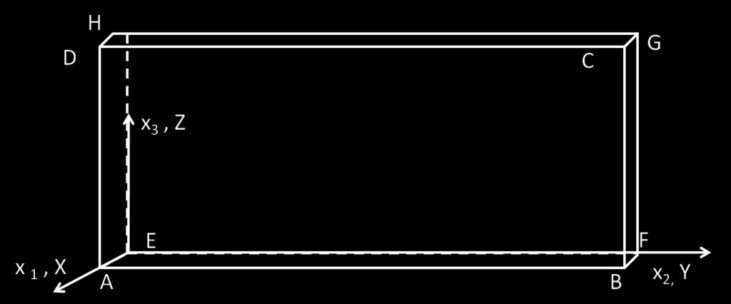
6 III. Computational Modeling Upscaled models of homogenized laminates are constructed for two different layups, with stacking of [( 45 2 /+45 2 /90 2 /0 2 )] s (Type A) and [( 45/+45/90/0) 2 ] s (Type B) as explained in Prabhakar and Waas, 24 where the 0 degree layers have a hexagonal packed fibers maintaining the micro-mechanics, and the off-axis layers are homogenized using Hill s anisotropic plasticity along with deformation theory of plasticity. Interface discrete cohesive zone method (DCZM) elements are added at critical interfaces which are determined a priori. This is determined using a simplified 2-D analysis of the laminate which is explained in the following sections. Finally, each laminate model is compressed in the global y-direction to predict the compressive strength and failure modes. A. Upscaled Laminate Model The upscaled homogenized models consist of 16-layers of laminae (see Fig. 5 and Fig. 6), where the off-axis layers i.e ,45 0,90 0 layers, are homogenized using the technique mentioned in Prabhakar and Waas. 24 Here, the red, cream and blue regions are the homogenized -45, +45 and 90 degree laminae. Micro-mechanics is maintained in the 0 0 layers, as they are the load bearing layers and are responsible for kink band formation in multi-directional laminates. Therefore, the regions in green are the 0 degree fibers, and regions in grey are the matrix in 0 degree lamina. Figure layered upscaled model of Type A laminate with homogenized off-axis laminae The homogenized elastic lamina properties of the off-axis laminae corresponding to a fiber volume fraction of 0.49 are given in Table 2 and Fig. 7. Other material properties are given in Table 3. The constants R ij required to implement Hill s anisotropic plasticity model are tabulated in Table 4 (note that R 11 is chosen to be an arbitrarily high value since the 1-direction of the lamina is assumed to be elastic throughout). These properties are applied to off-axis laminae in their rotated coordinates accounting for their ply orientations. Table 2. Fiber Properties E 11 (GPa) E 22 (GPa) E 33 (GPa) G 12 (GPa) G 13 (GPa) G 23 (GPa) ν 12 ν 13 ν A schematic of the two models shown in Fig. 8 is further used to describe the boundary conditions and loading on the model. The edge AE of the model is prevented from motion in the z-direction, and the corner E is fixed against moving in the global x, y and z-directions. The face BFGC is subjected to compression along the negative x-direction in a displacement control manner. The faces ABCD and EFGH are held flat 6 of 15
 E 22 (GPa) E 33 (GPa) G 12 (GPa) G 13 (GPa) G 23 (GPa) ν 12 ν 13 ν 23 136.81 5.397 5.")

7 Figure layered upscaled model of Type B laminate with homogenized off-axis laminae Equivalent stress (MPa) E s Equivalent strain Figure 7. Equivalent stress-strain curve for the in-situ matrix Table 3. Elastic Homogenized Lamina Properties E 11 (GPa) E 22 (GPa) E 33 (GPa) G 12 (GPa) G 13 (GPa) G 23 (GPa) ν 12 ν 13 ν Table 4. Values of R ij for calculating Hill s potential constants R 11 R 22 R 33 R 12 R 13 R but are allowed to expand or contract in the y-direction. Also, the faces ABCD and EFGH deform exactly the same way in x and z-directions. This enables the use of one representative unit cell in the y-direction, along with preserving a constant initial stiffness of the laminate, regardless of the width of the model. 7 of 15

 that can occur at limit points, as will be discussed later. The model is meshed with 3-D hexahedral elements (C3D8 in ABAQUS v6.10).")
8 Figure 8. A schematic of the laminate model to describe boundary conditions and loading The Riks method option available in ABAQUS v6.10, which is an arc-length solution scheme, is adopted to conduct the compressive response analysis. As shown in previous studies, 27 this method captures unstable equilibrium paths (path in the load vs. loaded edge displacement graph that show snap-back response) that can occur at limit points, as will be discussed later. The model is meshed with 3-D hexahedral elements (C3D8 in ABAQUS v6.10). The macroscopic stress is defined as the total resultant x-direction reaction force on the face BFGC divided by the product of the width BF and thickness BC, while the macroscopic strain is defined as the total contraction (change in length between the faces BFGC and AEHD) divided by the initial length AB. B. 2-D reduction formulation to determine a priori interfaces susceptible to delamination in a laminate After developing the upscaled laminate model, the interface most susceptible to delamination needs to be determined in order to add interface elements along that interface. Methods to carry out free edge effects, and to obtain the stresses along the interface of laminates have been formulated and presented in a series of papers by Pipes and Pagano, 28 Pagano et al., 29 Pagano and Pipes, 30 and more recently by Martin et al. 31 A generalized 2-D plane strain formulation using the FEM framework presented in Martin et al., 31 but using 3D elements is implemented here, and solved using the FE ABAQUS code. A brief overview of the formulation of the generalized 2-D framework is explained in the following section. 1. Mathematical Formulation Based on the formulation given in, 28 and, 31 a laminate of length 2L, width of 2b and lamina thickness equal to h is considered. The geometry of the laminate along with its boundaries is shown in Fig. 9(a). The layers in the laminate are in the x 1 -x 2 plane. A compressive load is applied at the edges Σ +L and Σ L along the x 1 direction. Edges Σ 0 and Σ 2b are the free edges in the x 2 direction. A cross-section of the laminate at A-A is shown in Fig. 9(b) that has N layers through the thickness. The p th interface between the laminae is represented by Γ p. At a region considerably far from the loading edges, the stress components are assumed to be independent of x 1. That is, the axial strain ɛ 11 is assumed to be uniform along the x 1 -direction within the laminate. This behavior was reported in 32 through Moire fringe patterns on the surfaces in the x 1 -x 2 plane of different laminates. A region considerably far from the loading surfaces is considered such that the stress components are assumed to be independent of x 1. Then, the displacement field is given as, U 1 (x 1, x 2, x 3 ) = Ũ1(x 2, x 3 ) + ɛ 11 x 1 U 2 (x 1, x 2, x 3 ) = Ũ2(x 2, x 3 ) U 3 (x 1, x 2, x 3 ) = Ũ3(x 2, x 3 ) (1) Here, ɛ 11 is the applied uniform axial strain in the laminate in the x 1 -direction. The constitutive law for each linear elastic lamina (3-D), in the tensorial form is, σ ij = a ijkl ɛ kl, where, i,j=1,2,3 within the laminate. 8 of 15
9 Here, a ijkl, is the fourth order linear elasticity tensor for a general anisotropic material. At the interface, we must ensure displacement and traction continuity, which are given by, Displacement Continuity : [U i ] = 0 Traction Continuity : [σ ij n j ] = 0 on the interface Γ p (2) At the traction free edges and the loading, we have, σ ij n j = 0 i = 1, 2, 3on Σ 0 and Σ 2b σ ij n j = F i on Σ +L (3) σ ij n j = F i on Σ L Weak form: Let V be a weighting field for the equilibrium equations, given by, V = average of the equilibrium equations are, Ω V 1 (x 2, x 3 ) V 2 (x 2, x 3 ) V 3 (x 2, x 3 ). The weighted σ ij V i x j = 0 (4) Since V = f(x 2, x 3 ) Vi x 1 = 0, which implies the weighting field is independent of x 1. Substituting the constitutive relation for σ ij into the above equation, we have, S Ũk V i a iαkh dx 2 dx 3 = ɛ 11 a iα11 V i n α ds (5) x h x α S where, s represents a coordinate that denotes the boundary S, starting at the origin of the x 2 -x 3 axes for the region S, and traversing in an anti-clockwise direction. Therefore, s is either x 2 or x 3 depending on the portion of the boundary being traversed. The above equation is modified to account for layers with different orientation in a multidirectional laminate as given below, N p=1 a p Ũ p k iαkh S p V p N i dx 2 dx 3 = ɛ 11 x h x α p=1 S p a p iα11 V p i np αds (6) Equation 7 is a generalized 2-D formulation which has displacement fields along the x 1,x 2 and x 3 directions, but in a 2-D (x 2 -x 3 plane) domain. The input to the above formulation is the 4th order elasticity tensor of each layer of the laminate for a linear elastic material and the applied external strain. The equivalent loads calculated for a laminate are applied to the 2-D generalized representation of the laminate in the FEM model given in the next section. 2. Implementation of the Generalized 2-D Formulation The 2-D generalized plane strain formulation presented above can be implemented in several ways using the finite element method. The method used here is to modify a thin slice of a 3-D model to behave like a generalized 2-D model. A 3-D model of a laminate (shown in Fig. 9(a)) with a small thickness in the x-direction is considered as shown in Fig. 2. The model is restricted from any expansion in the x-direction using multi-point constraints. This satisfies the requirement that the displacement fields are independent of the x-direction. This gives us the left hand side of equation (7) (refer to Martin et al. 31 ). N p=1 a p Ũ p k iαkh S p V p N i dx 2 dx 3 = ɛ 11 x h x α p=1 S p a p iα11 V p i np αds (7) The external loads are applied to the model on the edges in the y-z plane (refer to Fig. 9(b)) and the interfaces between the layers. 9 of 15


10 (a) (b) Figure 9. (a) 3-D laminate; (b) Cross-section of the 3-D laminate Figure D slice of a laminate 10 of 15
![3. Determination of Delamination Prone Interfaces in Laminates The above formulation is implemented for an 8-ply laminate with a stacking of [-45/+45/90/0]s (half of the laminate is used as shown in](/docs-images/72/66592415/images/11-0.jpg "Fig. 11(a)) to determine the weak interfaces. Fig. 11(b) shows the strains ɛ 33,ɛ 13 and ɛ 23 along the -45/+45 (Interface 1), +45/90 (Interface 2) and 90/0 (Interface 3) interfaces.")

11 3. Determination of Delamination Prone Interfaces in Laminates The above formulation is implemented for an 8-ply laminate with a stacking of [-45/+45/90/0]s (half of the laminate is used as shown in Fig. 11(a)) to determine the weak interfaces. Fig. 11(b) shows the strains ɛ 33,ɛ 13 and ɛ 23 along the -45/+45 (Interface 1), +45/90 (Interface 2) and 90/0 (Interface 3) interfaces. It is observed in Fig. 11(b) that ɛ 13 is very high at Interface 1 as compared to the strains at the other Interfaces. Therefore, Interface 1 is considered to be the interface that is most susceptible to delaminate. This information will be used in constructing the computational model of the laminate, i.e. the cohesive elements will be added along Interface 1 to allow for delamination at -45/+45 interfaces. Strain (a) Interface 1 :ε 33 Interface 1 :ε 13 Interface 1 :ε 23 Interface 2 :ε 33 Interface 2 :ε 13 Interface 2 :ε 23 Interface 3 :ε 33 Interface 3 :ε 13 Interface 3 :ε Normalized length along cross section (b) Figure 11. (a) Symmetric model representing an 8-ply laminate with a stacking of [ 45/ + 45/90/0] s; (b) Strains at the interfaces of an 8-ply laminate model C. DCZM Elements at Interfaces Based on the interface analysis carried out in the previous section, discrete cohesive zone method (DCZM) elements are added at the interfaces of the laminate to model delamination. The DCZM elements adopt a 1D traction law capable of simulating crack formation and propagation, i.e. delamination. The element features the ability to predict delamination initiation based on a traction law that captures the cohesive strength and the fracture toughness in each fracture mode (mode I, mode II and mode-iii in the current model). The DCZM elements used in this paper have been successfully employed in other studies involving crack propagation as presented in. 25 A triangular traction-separation law is used here. The inputs to the law are cohesive strengths in mode-i and mode-ii (σ c and τ c ), and fracture toughness in mode-i and mode-ii (G IC and G IIC ). The critical G IC and G IIC values are determined from the standard double cantilever beam (DCB) and edge notch flexure (ENF) tests, respectively (refer to 33 and 34 ). The mode-i cohesive strength is backed out from a DCB finite element virtual test, using experimentally determined mode-i fracture toughness as the input, and by varying the value of σ c until the load-deflection response matches the one determined experimentally. The mode-ii cohesive strength is determined through a single lap joint test of 15
12 The experimentally determined fracture properties for the laminate are given in Table 5. Table 5. Fracture properties of interfaces in the laminate G IC G IIC σ c τ c 0.67 ± 0.07 N/mm 1.67 ± 0.08 N/mm 15 ± 2.5 MPa 28 ± 2 MPa It should be noted here that the fracture properties determined are between 0 degree layers in a laminate. Each interlaminar interface between laminae of different orientation could have different fracture properties, especially in mode-ii. But, here, the fracture properties between all the interfaces in the laminate are assumed to be the same. D. Effects of Stacking on Compressive Strength and Failure Mode: Comparison of Type A and Type B Laminates In order to study the effect of stacking sequence on the compressive strength and failure mode in Type A and Type B laminates, the upscaled homogenized model described above is implemented with interface elements (DCZM) added along the critical interfaces determined a priori from the 2-D generalized plane strain analysis. Keeping the fracture toughnesses fixed at 0.67 N/mm and 1.67 N/mm in mode-i and mode-ii, the cohesive strengths are varied, and the corresponding global stress-strain responses are determined. A comparative investigation of Type A and Type B laminates is carried out in this section. The objective is to investigate the influence of stacking sequence on the compressive strength and failure mode in laminates. Therefore, the compressive response of the two different models was studied. The smallest model that represents the Type B 48 layer laminate is a 16 ply laminate with zero layers distributed through the thickness with a stacking sequence of [( 45/ + 45/90/0) 2 ]s. Type A 16-ply laminate is constructed by scaling the thickness of the individual layers in Type A 8-ply laminate. Compressive Strength (MPa) Experiment Type A Type B Mode II Cohesive Strength (MPa) (a) Compressive Strength (MPa) Type A Type B Experiment Imperfection Angle (degree) (b) Figure 12. (a) Variation of compressive strength of Type A and Type B laminates with varying mode-ii cohesive strength of the interfaces; (b) Imperfection sensitivity of Type A and Type B laminate models A slight imperfection is imparted to the model to account for fiber misalignment. Previous work 36 has shown that initial misalignment angles of 0.5 to 2 degrees of the zero laminae bound the distribution of fiber misalignment that is typical of carbon fiber reinforced pre-preg aerospace laminates. The imperfection imparted here is closer to experimentally observed behavior, i.e., only the center zero layers are seeded with 12 of 15


13 an imperfection of θ = δ/l. This is because, during the manufacturing process, the pressure and temperature applied on the top of the laminate causes noticeable undulations in the 0 fibers, as opposed to off-axis layers. The initial state in the compression analysis is stress free. The compressive strengths are determined for the two laminates corresponding to mode-ii cohesive strengths in the range of MPa with an imperfection angle of 1 degree. The compressive strengths are plotted against mode-ii cohesive strengths in Fig. 12(a). Here, we observe that the compressive strengths of both the laminates increase with increasing mode-ii cohesive strengths. Further, the compressive strength of Type B laminate increases faster as compared to that of Type A laminate with an increase in mode-ii cohesive strength. This indicates that, due to distributed 0 degree layers in the Type B laminate, the kink band failure in these laminates is influenced more by the interface fracture properties as compared to the Type A laminate. Having said that, the distributed nature of the 0 layers in Type B laminates also makes the loading on the model more uniform as compared to Type A laminate, where the off-axis layers are subjected to higher stresses compared to the 0 layers. This leads to a nearly 10 % increase in the compressive strength in Type B laminates. Next, the influence of the imperfection angle on the compressive strength is studied. For a fixed value of mode-ii cohesive strength, the imperfection angle is varied from 1 degree to 1.5 degrees, which is within the range of imperfection angles measured in aerospace grade laminates. As expected, the compressive strength reduces with an increase in the imperfection angle. The sensitivity of compressive strength to changes in imperfection angle was similar in both Type A and Type B laminates as seen in Fig. 12(b). The deformation shapes of the two laminate models with the same material and fracture input properties are shown in Fig. 13(a), Fig. 13(b) and Fig. 13(c) corresponding to the initial linear stage, at peak load and in the post-peak regime of the stress-strain response respectively. (a) (b) (c) Figure 13. Deformation shapes of Type A and Type B laminates (a) in the initial linear regime, (b) at the peak load and (c) in the post-peak regime of the global stress-strain response It is noticed that, in both the laminates, delamination is accompanied by kink band formation. But, the kink band in the Type B laminate is restricted to a smaller zone compared to the Type A laminate. This implies that, even though the compressive strength is influenced by interface fracture properties in both the laminates, the growth or extent of delamination in Type B laminates is less compared to Type A laminates. 13 of 15
14 This observation is consistent with experimental observations, where it is noted that Type A laminates fail in a catastrophic manner, whereas Type B laminates, after kink banding and delamination, remain intact post-experiment (as shown in Fig. 1(b) and Fig. 1(d), respectively). This suggests that Type B laminates are favored over Type A laminates for structural applications. Indeed, standard laminate design practices limit the number of adjacent plies having the same angle. IV. Conclusions Computational models to predict the compressive strength were constructed based on failure mechanisms observed in experiments. The model facilitates delamination to occur along those interfaces that are prone to delamination by adding cohesive (DCZM) interface elements along the selected interfaces. These interfaces were determined a-priori from the knowledge of the laminate stacking sequence and the geometry of the layers. The interfaces determined as the delamination prone interfaces match well with the experimentally observed delaminating interfaces. The properties of the DCZM elements were based on the interlaminar fracture properties that were determined experimentally. The predicted compressive strengths, when compared against the set of experimental results, were found to agree well, both in terms of the maximum load and the failure modes. The mode of failure is determined by the number and the orientation of the lamina in a laminate, the material shear nonlinearity (dictated by the matrix properties) and the interlaminar fracture properties. The methodology outlined in this paper can be used to quickly assess the compressive strength of laminates, within engineering limits, with a knowledge of the fundamental material properties as inputs. Thus, this method can be used very early in the design cycle of fiber reinforced laminated composite structures to establish design margins for strength allowables. That is, the compressive strength of the laminates with different combinations of layups, layer thicknesses and material properties can be investigated virtually. Further, only a handful of different types of laminates need to be manufactured and tested to decide on the final laminate to be used. This could result in a significant reduction of manufacturing and testing related costs. References 1 Schultheisz, C. R. and Waas, A. M., Compressive failure of composites.1. Testing and micromechanical theories, Progress in Aerospace Sciences, Vol. 32, No. 1, 1996, pp Waas, A. M. and Schultheisz, C. R., Compressive failure of composites.2. Experimental studies, Progress in Aerospace Sciences, Vol. 32, No. 1, 1996, pp Budiansky, B. and Fleck, N. A., Compressive failure of fiber composites, Journal of the Mechanics and Physics of Solids, Vol. 41, No. 1, 1993, pp Schapery, R. A., Prediction of compressive strength and kink bands in composites using a work potential, International Journal of Solids and Structures, Vol. 32, No. 6-7, 1995, pp Sun, C. T. and Jun, A. W., Compressive strength of unidirectional fiber composites with matrix non-linearity, Composites Science and Technology, Vol. 52, No. 4, 1994, pp Kyriakides, S., Arseculeratne, R., Perry, E. J., and Liechti, K. M., On the compressive failure of fiber-reinforced composites, International Journal of Solids and Structures, Vol. 32, No. 6-7, 1995, pp Lee, S. H. and Waas, A. M., Compressive response and failure of fiber reinforced unidirectional composites, International Journal of Fracture, Vol. 100, 1999, pp Vogler, T. J., Hsu, S. Y., and Kyriakides, S., On the initiation and growth of kink bands in fiber composites. Part II: analysis, International Journal of Solids and Structures, Vol. 38, 2001, pp Yerramalli, C. S. and Waas, A. M., A failure criterion for fiber reinforced polymer composites under combined compression-torsion loading, International Journal of Solids and Structures, Vol. 40, No. 5, 2003, pp Yerramalli, C. S. and Waas, A. M., The effect of fiber diameter on the compressive strength of composites - A 3D finite element based study, Computer Modeling in Engineering and Sciences, Vol. 6, No. 1, 2004, pp Basu, S., Waas, A. M., and Ambur, D. R., Compressive failure of fiber composites under multi-axial loading, Journal of the Mechanics and Physics of Solids, Vol. 54, No. 3, 2006, pp Pimenta, S., Gutkin, R., Pinho, S. T., and Robinson, P., A micromechanical model for kink-band formation: Part I Experimental study and numerical modelling, Composites Science and Technology, Vol. 69, 2009, pp Pimenta, S., Gutkin, R., Pinho, S. T., and Robinson, P., A micromechanical model for kink-band formation: Part II Analytical modelling, Composites Science and Technology, Vol. 69, 2009, pp Feld, N., Allix, O., and Baranger, E., Micro-mechanical prediction of UD laminates behavior under combined compression up to failure: influence of matrix degradation, Journal of Composite Materials, Vol. 45, No. 22, 2011, pp Lee, S. H., Yerramalli, C. S., and Waas, A. M., Compressive splitting response of glass-fiber reinforced unidirectional composites, Composites Science and Technology, Vol. 60, 2000, pp Waas, A. M., Babcock Jr., C. D., and Knauss, W. G., An experimental study of compression failure of fibrous laminated 14 of 15
15 composites in the presence of stress gradients, International Journal of Solids and Structures, Vol. 26, No. 9-10, 1990, pp Ahn, J. H. and Waas, A. M., A micromechanics-based finite element model for compressive failure of notched uniply composite laminates under remote biaxial loads, Journal of Engineering Materials and Technology - Transactions of the ASME, Vol. 121, No. 3, 1999, pp Ahn, J. H. and Waas, A. M., Prediction of compressive failure in laminated composites at room and elevated temperature, AIAA Journal, Vol. 40, No. 2, 2002, pp Berbinau, P., Soutis, C., and Guz, I. A., Compressive failure of 0 0 unidirectional carbon-fibre-reinforced plastic (CFRP) laminates by fibre microbuckling, Composites Science and Technology, Vol. 59, 1999, pp Wisnom, M. R., The Effect of Fibre Waviness on the Relationship between Compressive and Flexural Strengths of Unidirectional Composites, Journal of Composite Materials, Vol. 28, Naik, N. K. and Kumar, R. S., Compressive strength of unidirectional composites: evaluation and comparison of prediction models, Composite Structures, Vol. 46, No. 3, 1999, pp Xu, Y. L. and Reifsnider, K. L., Micromechanical Modeling of Composite Compressive Strength, Journal of Composite Materials, Vol. 27, 1993, pp Yerramalli, C. S. and Waas, A. M., A nondimensional number to classify composite compressive failure, Journal of Applied Mechanics - Transactions of the ASME, Vol. 71, No. 3, 2004, pp Prabhakar, P. and Waas, A., Upscaling from a micro-mechanics model to capture laminate compressive strength due to kink banding instability, Computational Materials Science, Vol. 67, No. 0, 2013, pp Gustafson, P. and Waas, A., The influence of adhesive constitutive parameters in cohesive zone finite element models of adhesively bonded joints, International Journal of Solids and Structures, Vol. 46, No. 10, 2009, pp ARAMIS, ARAMIS Software Documentation, GOM Optical Measuring Teqhniques, Beghini, A., Bazant, Z. P., Waas, A. M., and Basu, S., Postcritical imperfection sensitivity of sandwich or homogenized orthotropic columns soft in shear and in transverse deformation, International Journal of Solids and Structures, Vol. 43, No , 2006, pp Pipes, R. B. and Pagano, N. J., Interlaminar Stresses in Composite Laminates Under Uniform Axial Extension, Journal of Composite Materials, Vol. 4, Pagano, N. and Pipes, R., The Influence of Stacking Sequence on Laminate Strength, Journal of Composite Materials, Vol. 5, No. 1, 1971, pp Pagano, N. and Pipes, R., Some observations on the interlaminar strength of composite laminates, International Journal of Mechanical Sciences, Vol. 15, No. 8, 1973, pp Martin, E., Leguillon, D., and Carrere, N., A twofold strength and toughness criterion for the onset of free-edge shear delamination in angle-ply laminates, International Journal of Solids and Structures, Vol. 47, No. 9, 2012, pp Pipes, R. B. and Daniel, I. M., Moiré Analysis of the Interlaminar Shear Edge Effect in Laminated Composites, Journal of Composite Materials, Vol. 5, ASTM(D5528), Standard Test Method for Mode I Interlaminar Fracture Toughness of Unidirectional Fiber-Reinforced Polymer Matrix Composites, Davidson, B. D. and Sun, X., Geometry and Data Reduction Recommendations for a Standardized End Notched Flexure Test for Unidirectional Composites, Journal of ASTM International, Vol. 3, ASTM(D3165), Standard Test Method for Strength Properties of Adhesives in Shear by Tension Loading of Single-Lap- Joint Laminated Assemblies, Yurgartis, S. W., Measurement of small angle fiber misalignments in continuous fiber composites, Composites Science and Technology, Vol. 30, 1987, pp of 15
KINK BAND FORMATION OF FIBER REINFORCED POLYMER (FRP)
") KINK BAND FORMATION OF FIBER REINFORCED POLYMER (FRP) 1 University of Science & Technology Beijing, China, niukm@ustb.edu.cn 2 Tsinghua University, Department of Engineering Mechanics, Beijing, China,
KINK BAND FORMATION OF FIBER REINFORCED POLYMER (FRP) 1 University of Science & Technology Beijing, China, niukm@ustb.edu.cn 2 Tsinghua University, Department of Engineering Mechanics, Beijing, China,
Effect of Fiber Waviness on the Compressive Strength of Unidirectional Carbon Fiber Composites
 53rd AIAA/ASME/ASCE/AHS/ASC Structures, Structural Dynamics and Materials Conference20th AI 23-26 April 2012, Honolulu, Hawaii AIAA 2012-1422 Effect of Fiber Waviness on the Compressive Strength of
SDM 2013 Student Papers Competition Modeling fiber-matrix splitting failure through a mesh-objective continuum-decohesive finite element method
 Structures, Structural Dynamics, and Materials and Co-located Conferences April 8-11, 2013, Boston, Massachusetts 54th AIAA/ASME/ASCE/AHS/ASC Structures, Structural Dynamics, and Materials Conference AIAA
Open-hole compressive strength prediction of CFRP composite laminates
 Open-hole compressive strength prediction of CFRP composite laminates O. İnal 1, A. Ataş 2,* 1 Department of Mechanical Engineering, Balikesir University, Balikesir, 10145, Turkey, inal@balikesir.edu.tr
A Unified Model for Predicting the Open Hole Tensile and Compressive Strengths of Composite Laminates for Aerospace Applications
 Structures, Structural Dynamics, and Materials and Co-located Conferences April 8-11, 2013, Boston, Massachusetts 54th AIAA/ASME/ASCE/AHS/ASC Structures, Structural Dynamics, and Materials Conference AIAA
NUMERICAL INVESTIGATION OF DELAMINATION IN L-SHAPED CROSS-PLY COMPOSITE BRACKET
 NUMERICAL INVESTIGATION OF DELAMINATION IN L-SHAPED CROSS-PLY COMPOSITE BRACKET M.Gümüş a*, B.Gözlüklü a, D.Çöker a a Department of Aerospace Eng., METU, Ankara, Turkey *mert.gumus@metu.edu.tr Keywords:
Computational Analysis for Composites
 Computational Analysis for Composites Professor Johann Sienz and Dr. Tony Murmu Swansea University July, 011 The topics covered include: OUTLINE Overview of composites and their applications Micromechanics
Tensile behaviour of anti-symmetric CFRP composite
 Available online at www.sciencedirect.com Procedia Engineering 1 (211) 1865 187 ICM11 Tensile behaviour of anti-symmetric CFRP composite K. J. Wong a,b, *, X. J. Gong a, S. Aivazzadeh a, M. N. Tamin b
COMPARISON OF COHESIVE ZONE MODELS USED TO PREDICT DELAMINATION INITIATED FROM FREE-EDGES : VALIDATION AGAINST EXPERIMENTAL RESULTS
 COMPARISON OF COHESIVE ZONE MODELS USED TO PREDICT DELAMINATION INITIATED FROM FREE-EDGES : VALIDATION AGAINST EXPERIMENTAL RESULTS A. Uguen 1, L. Zubillaga 2, A. Turon 3, N. Carrère 1 1 Laboratoire Brestois
Keywords: CFRP, compressive failure, kink-band, cohesive zone model. * Corresponding author
 THE 19 TH INTERNATIONAL CONFERENCE ON COMPOSITE MATERIALS AN EXPERIMENTAL METHOD TO DETERMINE THE CRITICAL ENERGY RELEASE RATE ASSOCIATED WITH LONGITUDINAL COMPRESSIVE FAILURE IN CFRP D. Svensson 1 *,
Experimental methods to determine model parameters for failure modes of CFRP
 Experimental methods to determine model parameters for failure modes of CFRP DANIEL SVENSSON Department of Applied Mechanics CHALMERS UNIVERSITY OF TECHNOLOGY Göteborg, Sweden 213 THESIS FOR THE DEGREE
FINITE ELEMENT ANALYSIS OF COMPOSITE MATERIALS
 FINITE ELEMENT ANALYSIS OF COMPOSITE MATERIALS Ever J. Barbero Department of Mechanical and Aerospace Engineering West Virginia University USA CRC Press Taylor &.Francis Group Boca Raton London New York
Finite element modelling of infinitely wide Angle-ply FRP. laminates
 www.ijaser.com 2012 by the authors Licensee IJASER- Under Creative Commons License 3.0 editorial@ijaser.com Research article ISSN 2277 9442 Finite element modelling of infinitely wide Angle-ply FRP laminates
Experimentally Calibrating Cohesive Zone Models for Structural Automotive Adhesives
 Experimentally Calibrating Cohesive Zone Models for Structural Automotive Adhesives Mark Oliver October 19, 2016 Adhesives and Sealants Council Fall Convention contact@veryst.com www.veryst.com Outline
Size Effects In the Crushing of Honeycomb Structures
 45th AIAA/ASME/ASCE/AHS/ASC Structures, Structural Dynamics & Materials Conference 19-22 April 2004, Palm Springs, California AIAA 2004-1640 Size Effects In the Crushing of Honeycomb Structures Erik C.
Fig. 1. Different locus of failure and crack trajectories observed in mode I testing of adhesively bonded double cantilever beam (DCB) specimens.
 specimens.") a). Cohesive Failure b). Interfacial Failure c). Oscillatory Failure d). Alternating Failure Fig. 1. Different locus of failure and crack trajectories observed in mode I testing of adhesively bonded double
a). Cohesive Failure b). Interfacial Failure c). Oscillatory Failure d). Alternating Failure Fig. 1. Different locus of failure and crack trajectories observed in mode I testing of adhesively bonded double
Numerical simulation of delamination onset and growth in laminated composites
 Numerical simulation of delamination onset and growth in laminated composites G. Wimmer, C. Schuecker, H.E. Pettermann Austrian Aeronautics Research (AAR) / Network for Materials and Engineering at the
Numerical Analysis of Delamination Behavior in Laminated Composite with Double Delaminations Embedded in Different Depth Positions
 Numerical Analysis of Delamination Behavior in Laminated Composite with Double Delaminations Embedded in Different Depth Positions Numerical Analysis of Delamination Behavior in Laminated Composite with
INTERNATIONAL JOURNAL OF APPLIED ENGINEERING RESEARCH, DINDIGUL Volume 2, No 1, 2011
 Interlaminar failure analysis of FRP cross ply laminate with elliptical cutout Venkateswara Rao.S 1, Sd. Abdul Kalam 1, Srilakshmi.S 1, Bala Krishna Murthy.V 2 1 Mechanical Engineering Department, P. V.
Progressive Failure Analysis on Textile Composites
 AIAA SciTech Forum 13-17 January 014, National Harbor, Maryland 55th AIAA/ASME/ASCE/AHS/ASC Structures, Structural Dynamics, and Materials Conference 10.514/6.014-0157 Progressive Failure Analysis on Textile
Compressive splitting failure of composites using modified shear lag theory
 International Journal of Fracture 115: 27 40, 2002. 2002 Kluwer Academic Publishers. Printed in the Netherlands. Compressive splitting failure of composites using modified shear lag theory CHANDRA S. YERRAMALLI
University of Bristol - Explore Bristol Research. Early version, also known as pre-print
 Hallett, S. R., & Wisnom, M. R. (2006). Numerical investigation of progressive damage and the effect of layup in notched tensile tests. Journal of Composite Materials, 40 (14), 1229-1245. DOI: 10.1177/0021998305057432
SIZE EFFECTS IN THE COMPRESSIVE CRUSHING OF HONEYCOMBS
 43rd AIAA/ASME/ASCE/AHS/ASC Structures, Structural Dynamics, and Materials Con 22-25 April 2002, Denver, Colorado SIZE EFFECTS IN THE COMPRESSIVE CRUSHING OF HONEYCOMBS Erik C. Mellquistand Anthony M.
Multi Disciplinary Delamination Studies In Frp Composites Using 3d Finite Element Analysis Mohan Rentala
 Multi Disciplinary Delamination Studies In Frp Composites Using 3d Finite Element Analysis Mohan Rentala Abstract: FRP laminated composites have been extensively used in Aerospace and allied industries
PROGRESSIVE DAMAGE ANALYSES OF SKIN/STRINGER DEBONDING. C. G. Dávila, P. P. Camanho, and M. F. de Moura
 PROGRESSIVE DAMAGE ANALYSES OF SKIN/STRINGER DEBONDING C. G. Dávila, P. P. Camanho, and M. F. de Moura Abstract The debonding of skin/stringer constructions is analyzed using a step-by-step simulation
QUESTION BANK Composite Materials
 QUESTION BANK Composite Materials 1. Define composite material. 2. What is the need for composite material? 3. Mention important characterits of composite material 4. Give examples for fiber material 5.
Fracture Behaviour of FRP Cross-Ply Laminate With Embedded Delamination Subjected To Transverse Load
 Fracture Behaviour of FRP Cross-Ply Laminate With Embedded Delamination Subjected To Transverse Load Sriram Chintapalli 1, S.Srilakshmi 1 1 Dept. of Mech. Engg., P. V. P. Siddhartha Institute of Technology.
BIAXIAL STRENGTH INVESTIGATION OF CFRP COMPOSITE LAMINATES BY USING CRUCIFORM SPECIMENS
 BIAXIAL STRENGTH INVESTIGATION OF CFRP COMPOSITE LAMINATES BY USING CRUCIFORM SPECIMENS H. Kumazawa and T. Takatoya Airframes and Structures Group, Japan Aerospace Exploration Agency 6-13-1, Ohsawa, Mitaka,
THE ROLE OF DELAMINATION IN NOTCHED AND UNNOTCHED TENSILE STRENGTH
 THE ROLE OF DELAMINATION IN NOTCHED AND UNNOTCHED TENSILE STRENGTH M. R. Wisnom University of Bristol Advanced Composites Centre for Innovation and Science University Walk, Bristol BS8 1TR, UK M.Wisnom@bristol.ac.uk
Autodesk Helius PFA. Guidelines for Determining Finite Element Cohesive Material Parameters
 Autodesk Helius PFA Guidelines for Determining Finite Element Cohesive Material Parameters Contents Introduction...1 Determining Cohesive Parameters for Finite Element Analysis...2 What Test Specimens
Fracture Mechanics, Damage and Fatigue: Composites
 University of Liège Aerospace & Mechanical Engineering Fracture Mechanics, Damage and Fatigue: Composites Ludovic Noels Computational & Multiscale Mechanics of Materials CM3 http://www.ltas-cm3.ulg.ac.be/
COMPRESSIVE BEHAVIOR OF IMPACT DAMAGED COMPOSITE LAMINATES
 16 TH INTERNATIONAL CONFERENCE ON COMPOSITE MATERIALS COMPRESSIVE BEHAVIOR OF IMPACT DAMAGED COMPOSITE LAMINATES Hiroshi Suemasu*, Wataru Sasaki**, Yuuichiro Aoki***, Takashi Ishikawa**** *Department of
Material Characterization of Carbon Fiber Reinforced Polymer Laminate Using Virtual Fields Method
 Proceedings of ICTACEM 014 International Conference on Theoretical, Applied, Computational and Experimental Mechanics December 9-31, 014, IIT Kharagpur, India ICTACEM-014/39 Material Characterization of
A RESEARCH ON NONLINEAR STABILITY AND FAILURE OF THIN- WALLED COMPOSITE COLUMNS WITH OPEN CROSS-SECTION
 A RESEARCH ON NONLINEAR STABILITY AND FAILURE OF THIN- WALLED COMPOSITE COLUMNS WITH OPEN CROSS-SECTION H. Debski a*, J. Bienias b, P. Jakubczak b a Faculty of Mechanical Engineering, Department of Machine
Module III - Macro-mechanics of Lamina. Lecture 23. Macro-Mechanics of Lamina
 Module III - Macro-mechanics of Lamina Lecture 23 Macro-Mechanics of Lamina For better understanding of the macromechanics of lamina, the knowledge of the material properties in essential. Therefore, the
REPRESENTING MATRIX CRACKS THROUGH DECOMPOSITION OF THE DEFORMATION GRADIENT TENSOR IN CONTINUUM DAMAGE MECHANICS METHODS
 20 th International Conference on Composite Materials Copenhagen, 19-24 th July 2015 REPRESENTING MATRIX CRACKS THROUGH DECOMPOSITION OF THE DEFORMATION GRADIENT TENSOR IN CONTINUUM DAMAGE MECHANICS METHODS
ADVANCES IN THE PROGRESSIVE DAMAGE ANALYSIS OF COMPOSITES
 NAFEMS WORLD CONGRESS 13, SALZBURG, AUSTRIA ADVANCES IN THE PROGRESSIVE DAMAGE ANALYSIS OF M. Bruyneel, J.P. Delsemme, P. Jetteur (LMS Samtech, Belgium); A.C. Goupil (ISMANS, France). Dr. Ir. M. Bruyneel,
Prediction of Compressive Strength of Fibrous Composites Using Two Different Approaches
 Jordan Journal of Civil Engineering, Volume 8, No. 2, 214 Prediction of Compressive Strength of Fibrous Composites Using Two Different Approaches Yousef S. Al Rjoub 1) * and Karim S. Numayr 2) 1) Civil
Calculation of Energy Release Rate in Mode I Delamination of Angle Ply Laminated Composites
 Copyright c 2007 ICCES ICCES, vol.1, no.2, pp.61-67, 2007 Calculation of Energy Release Rate in Mode I Delamination of Angle Ply Laminated Composites K. Gordnian 1, H. Hadavinia 1, G. Simpson 1 and A.
SANDWICH COMPOSITE BEAMS for STRUCTURAL APPLICATIONS
 SANDWICH COMPOSITE BEAMS for STRUCTURAL APPLICATIONS de Aguiar, José M., josemaguiar@gmail.com Faculdade de Tecnologia de São Paulo, FATEC-SP Centro Estadual de Educação Tecnológica Paula Souza. CEETEPS
ISSN: ISO 9001:2008 Certified International Journal of Engineering Science and Innovative Technology (IJESIT) Volume 2, Issue 4, July 2013
 Volume 2, Issue 4, July 2013") Delamination Studies in Fibre-Reinforced Polymer Composites K.Kantha Rao, Dr P. Shailesh, K. Vijay Kumar 1 Associate Professor, Narasimha Reddy Engineering College Hyderabad. 2 Professor, St. Peter s Engineering
Delamination Studies in Fibre-Reinforced Polymer Composites K.Kantha Rao, Dr P. Shailesh, K. Vijay Kumar 1 Associate Professor, Narasimha Reddy Engineering College Hyderabad. 2 Professor, St. Peter s Engineering
Prediction of Delamination Growth Behavior in a Carbon Fiber Composite Laminate Subjected to Constant Amplitude Compression-Compression Fatigue Loads
 Prediction of Delamination Growth Behavior in a Carbon Fiber Composite Laminate Subjected to Constant Amplitude Compression-Compression Fatigue Loads J. Raju 1*, D.S. Sreedhar 2, & C.M. Manjunatha 1 1
Module 4: Behaviour of a Laminae-II. Learning Unit 1: M1. M4.1 Mechanics of Composites. M4.1.1 Introduction to Mechanics of Composites
 Module 4: Behaviour of a Laminae-II Learning Unit 1: M1 M4.1 Mechanics of Composites M4.1.1 Introduction to Mechanics of Composites The relation between ply uniaxial strengths and constituent properties
SSRG International Journal of Mechanical Engineering (SSRG-IJME) volume1 issue5 September 2014
 volume1 issue5 September 2014") Finite Element Modeling for Delamination Analysis of Double Cantilever Beam Specimen Mohammed Waseem H.S. 1, Kiran Kumar N. 2 1 Post Graduate Student, 2 Asst. Professor Dept. of Mechanical Engineering,
Finite Element Modeling for Delamination Analysis of Double Cantilever Beam Specimen Mohammed Waseem H.S. 1, Kiran Kumar N. 2 1 Post Graduate Student, 2 Asst. Professor Dept. of Mechanical Engineering,
Modelling the nonlinear shear stress-strain response of glass fibrereinforced composites. Part II: Model development and finite element simulations
 Modelling the nonlinear shear stress-strain response of glass fibrereinforced composites. Part II: Model development and finite element simulations W. Van Paepegem *, I. De Baere and J. Degrieck Ghent
Multiscale Approach to Damage Analysis of Laminated Composite Structures
 Multiscale Approach to Damage Analysis of Laminated Composite Structures D. Ivančević and I. Smojver Department of Aeronautical Engineering, Faculty of Mechanical Engineering and Naval Architecture, University
Impact and Crash Modeling of Composite Structures: A Challenge for Damage Mechanics
 Impact and Crash Modeling of Composite Structures: A Challenge for Damage Mechanics Dr. A. Johnson DLR Dr. A. K. Pickett ESI GmbH EURO-PAM 99 Impact and Crash Modelling of Composite Structures: A Challenge
THE MUTUAL EFFECTS OF SHEAR AND TRANSVERSE DAMAGE IN POLYMERIC COMPOSITES
 THE 19 TH INTERNATIONAL CONFERENCE ON COMPOSITE MATERIALS THE MUTUAL EFFECTS OF SHEAR AND TRANSVERSE DAMAGE IN POLYMERIC COMPOSITES L.V. Smith 1 *, M. Salavatian 1 1 School of Mechanical and Materials
PREDICTION OF OUT-OF-PLANE FAILURE MODES IN CFRP
 PREDICTION OF OUT-OF-PLANE FAILURE MODES IN CFRP R. R. Pinto 1, P. P. Camanho 2 1 INEGI - Instituto de Engenharia Mecanica e Gestao Industrial, Rua Dr. Roberto Frias, 4200-465, Porto, Portugal 2 DEMec,
Investigation of progressive damage and fracture in laminated composites using the smeared crack approach
 53rd AIAA/ASME/ASCE/AHS/ASC Structures, Structural Dynamics and Materials Conference20th AI 23-26 April 2012, Honolulu, Hawaii AIAA 2012-1537 Investigation of progressive damage and fracture in laminated
INITIATION AND PROPAGATION OF FIBER FAILURE IN COMPOSITE LAMINATES
 THE 19 TH INTERNATIONAL CONFERENCE ON COMPOSITE MATERIALS INITIATION AND PROPAGATION OF FIBER FAILURE IN COMPOSITE LAMINATES E. Iarve 1,2*, D. Mollenhauer 1, T. Breitzman 1, K. Hoos 2, M. Swindeman 2 1
Comparison of Ply-wise Stress-Strain results for graphite/epoxy laminated plate subjected to in-plane normal loads using CLT and ANSYS ACP PrepPost
 Comparison of Ply-wise Stress-Strain results for graphite/epoxy laminated plate subjected to in-plane normal loads using CLT and ANSYS ACP PrepPost 1 Mihir A. Mehta, 2 Satyen D. Ramani 1 PG Student, Department
Numerical Simulation of the Mode I Fracture of Angle-ply Composites Using the Exponential Cohesive Zone Model
 Numerical Simulation of the Mode I Fracture of Angle-ply Composites Using the Exponential Cohesive Zone Model Numerical Simulation of the Mode I Fracture of Angle-ply Composites Using the Exponential Cohesive
EXPERIMENTAL CHARACTERIZATION AND COHESIVE LAWS FOR DELAMINATION OF OFF-AXIS GFRP LAMINATES
 20 th International Conference on Composite Materials Copenhagen, 19-24 th July 2015 EXPERIMENTAL CHARACTERIZATION AND COHESIVE LAWS FOR DELAMINATION OF OFF-AXIS GFRP LAMINATES Esben Lindgaard 1 and Brian
MECHANICAL FAILURE OF A COMPOSITE HELICOPTER STRUCTURE UNDER STATIC LOADING
 MECHANICAL FAILURE OF A COMPOSITE HELICOPTER STRUCTURE UNDER STATIC LOADING Steven Roy, Larry Lessard Dept. of Mechanical Engineering, McGill University, Montreal, Québec, Canada ABSTRACT The design and
Benchmarking study of steel-composite structures in CAE crash applications. Master s thesis in Applied Mechanics MADELEINE ANDERSSON EMMA LARSSON
 Benchmarking study of steel-composite structures in CAE crash applications Master s thesis in Applied Mechanics MADELEINE ANDERSSON EMMA LARSSON Department of Applied Mechanics CHALMERS UNIVERSITY OF TECHNOLOGY
Mixed-Mode Fracture Toughness Determination USING NON-CONVENTIONAL TECHNIQUES
 Mixed-Mode Fracture Toughness Determination USING NON-CONVENTIONAL TECHNIQUES IDMEC- Pólo FEUP DEMec - FEUP ESM Virginia Tech motivation fracture modes conventional tests [mode I] conventional tests [mode
Comparison between a Cohesive Zone Model and a Continuum Damage Model in Predicting Mode-I Fracture Behavior of Adhesively Bonded Joints
 Copyright 2012 Tech Science Press CMES, vol.83, no.2, pp.169-181, 2012 Comparison between a Cohesive Zone Model and a Continuum Damage Model in Predicting Mode-I Fracture Behavior of Adhesively Bonded
RATE-DEPENDENT OFF-AXIS COMPRESSIVE STRENGTH OF A UNIDIRECTIONAL CARBON/EPOXY LAMINATE AT HIGH TEMPERATURE
 16 TH INTERNATIONAL CONFERENCE ON COMPOSITE MATERIALS RATE-DEPENDENT OFF-AXIS COMPRESSIVE STRENGTH OF A UNIDIRECTIONAL CARBON/EPOXY LAMINATE AT HIGH TEMPERATURE Masamichi KAWAI *, Satoru SAITO **, Jian-Qi
On characterising fracture resistance in mode-i delamination
 9 th International Congress of Croatian Society of Mechanics 18-22 September 2018 Split, Croatia On characterising fracture resistance in mode-i delamination Leo ŠKEC *, Giulio ALFANO +, Gordan JELENIĆ
APPLICATION OF A SCALAR STRAIN-BASED DAMAGE ONSET THEORY TO THE FAILURE OF A COMPLEX COMPOSITE SPECIMEN
 28 TH INTERNATIONAL CONGRESS OF THE AERONAUTICAL SCIENCES APPLICATION OF A SCALAR STRAIN-BASED DAMAGE ONSET THEORY TO THE FAILURE OF A COMPLEX COMPOSITE SPECIMEN Tuyen Tran*, Dan Simkins**, Shen Hin Lim*,
IMPACT ON LAMINATED COMPOSITE PLATES: COMPARISON OF TEST AND SIMULATION RESULTS OBTAINED WITH LMS SAMTECH SAMCEF
 V ECCOMAS Thematic Conference on the Mechanical Response of Composites COMPOSITES 015 S.R. Hallett and J.J.C. Remmers (Editors) IMPACT ON LAMINATED COMPOSITE PLATES: COMPARISON OF TEST AND SIMULATION RESULTS
DAMAGE SIMULATION OF CFRP LAMINATES UNDER HIGH VELOCITY PROJECTILE IMPACT
 18 TH INTERNATIONAL CONFERENCE ON COMPOSITE MATERIALS DAMAGE SIMULATION OF CFRP LAMINATES UNDER HIGH VELOCITY PROJECTILE IMPACT A. Yoshimura 1*, T. Okabe, M. Yamada 3, T. Ogasawara 1, Y. Tanabe 3 1 Advanced
MICROMECHANICAL ANALYSIS OF FRP COMPOSITES SUBJECTED TO LONGITUDINAL LOADING
 MICROMECHANICAL ANALYSIS OF FRP COMPOSITES SUBJECTED TO LONGITUDINAL LOADING N. Krishna Vihari 1, P. Phani Prasanthi 1, V. Bala Krishna Murthy 2* and A. Srihari Prasad 3 1 Mech. Engg. Dept., P. V. P. Siddhartha
Modeling and Simulations of Aircraft Structures Stiffness, Damage, and Failure Prediction for Laminated Composites
 Modeling and Simulations of Aircraft Structures Stiffness, Damage, and Failure Prediction for Laminated Composites H.E.Pettermann 1, C.Schuecker 1, D.H.Pahr 2, F.G.Rammerstorfer 2 1 Austrian Aeronautics
Strength of GRP-laminates with multiple fragment damages
 Strength of GRP-laminates with multiple fragment damages S. Kazemahvazi, J. Kiele, D. Zenkert Kungliga Tekniska Högskolan, KTH 100 44 Stockholm, Sweden sohrabk@kth.se SUMMARY The strength of glass fibre
FRACTURE TOUGHNESS OF ADHESIVE BONDED COMPOSITE JOINTS UNDER MIXED MODE LOADING.
 FRACTURE TOUGHNESS OF ADHESIVE BONDED COMPOSITE JOINTS UNDER MIXED MODE LOADING. X. J. Gong, F. Hernandez, G. Verchery. ISAT - Institut Supérieur de l Automobile et des Transports, LRMA - Laboratoire de
Fracture Mechanics of Composites with Residual Thermal Stresses
 J. A. Nairn Material Science & Engineering, University of Utah, Salt Lake City, Utah 84 Fracture Mechanics of Composites with Residual Thermal Stresses The problem of calculating the energy release rate
The Accuracy of Characteristic Length Method on Failure Load Prediction of Composite Pinned Joints
 , June 30 - July 2, 2010, London, U.K. The Accuracy of Characteristic Length Method on Failure Load Prediction of Composite Pinned Joints O. Aluko, and Q. Mazumder Abstract An analytical model was developed
Interlaminar fracture characterization in composite materials by using acoustic emission
 5th International Symposium on NDT in Aerospace, 13-15th November 2013, Singapore Interlaminar fracture characterization in composite materials by using acoustic emission Ian SILVERSIDES 1, Ahmed MASLOUHI
Project MMS13 Task 5 Report No 3 (M6/D3)
") Project MMS13 Task 5 Report No 3 (M6/D3) Material Data Requirements and Recommended Test Methods for the Predictive Modelling of Defect Criticality in Composite Material Systems M R L Gower and G D Sims
Project MMS13 Task 5 Report No 3 (M6/D3) Material Data Requirements and Recommended Test Methods for the Predictive Modelling of Defect Criticality in Composite Material Systems M R L Gower and G D Sims
A FINITE ELEMENT MODEL TO PREDICT MULTI- AXIAL STRESS-STRAIN RESPONSE OF CERAMIC MATRIX COMPOSITES WITH STRAIN INDUCED DAMAGE
 A FINITE ELEMENT MODEL TO PREDICT MULTI- AXIAL STRESS-STRAIN RESPONSE OF CERAMIC MATRIX COMPOSITES WITH STRAIN INDUCED DAMAGE Daxu Zhang and D. R. Hayhurst School of Mechanical, Aerospace and Civil Engineering,
Materials and Structures. Indian Institute of Technology Kanpur
 Introduction to Composite Materials and Structures Nachiketa Tiwari Indian Institute of Technology Kanpur Lecture 16 Behavior of Unidirectional Composites Lecture Overview Mt Material ilaxes in unidirectional
CHARACTERIZATION, ANALYSIS AND PREDICTION OF DELAMINATION IN COMPOSITES USING FRACTURE MECHANICS
 Oral Reference Number: ICF100942OR CHARACTERIZATION, ANALYSIS AND PREDICTION OF DELAMINATION IN COMPOSITES USING FRACTURE MECHANICS T. Kevin O Brien U.S. Army Research Laboratory Vehicle Technology Directorate
Most of the material in this package is based on a recently published book. This is:
 Mechanics of Composite Materials Version 2.1 Bill Clyne, University of Cambridge Boban Tanovic, MATTER Assumed Pre-knowledge It is assumed that the student is familiar with simple concepts of mechanical
FLOATING NODE METHOD AND VIRTUAL CRACK CLOSURE TECHNIQUE FOR MODELING MATRIX CRACKING- DELAMINATION MIGRATION
 THE 19 TH INTERNATIONAL CONFERENCE ON COMPOSITE MATERIALS FLOATING NODE METHOD AND VIRTUAL CRACK CLOSURE TECHNIQUE FOR MODELING MATRIX CRACKING- DELAMINATION MIGRATION N. V. De Carvalho 1*, B. Y. Chen
Failure analysis of serial pinned joints in composite materials
 Indian Journal of Engineering & Materials Sciences Vol. 18, April 2011, pp. 102-110 Failure analysis of serial pinned joints in composite materials Alaattin Aktaş* Department of Mechanical Engineering,
Micromechanical analysis of FRP hybrid composite lamina for in-plane transverse loading
 Indian Journal of Engineering & Materials Sciences Vol. 15, October 2008, pp. 382-390 Micromechanical analysis of FRP hybrid composite lamina for in-plane transverse loading K Sivaji Babu a *, K Mohana
NUMERICAL AND EXPERIMENTAL ANALYSES OF MULTIPLE DELAMINATIONS IN CURVED COMPOSITE LAMINATES
 THE 19 TH INTERNATIONAL CONFERENCE ON COMPOSITE MATERIALS NUMERICAL AND EXPERIMENTAL ANALYSES OF MULTIPLE DELAMINATIONS IN CURVED COMPOSITE LAMINATES A. Baldi 1 *, A. Airoldi 1, P. Belotti 1, P. Bettini
A SELF-INDICATING MODE I INTERLAMINAR TOUGHNESS TEST
 A SELF-INDICATING MODE I INTERLAMINAR TOUGHNESS TEST P. Robinson The Composites Centre, Department of Aeronautics, Imperial College London South Kensington, London, SW7 2AZ, UK p.robinson@imperial.ac.uk
FAILURE CRITERIA FOR COMPOSITE MATERIALS UNDER MULTIAXIAL STRESS STATES
 FAILURE CRITERIA FOR COMPOSITE MATERIALS UNDER MULTIAXIAL STRESS STATES Essam Totry 1, Carlos González 1, 2 and Javier LLorca 1, 2 1 Departmento de Ciencia de Materiales, Universidad Politécnica de Madrid.
Effects of Resin and Fabric Structure
 Fatigue of Wind Blade Laminates: Effects of Resin and Fabric Structure Details David Miller, Daniel D. Samborsky and John F. Mandell Montana State t University it MCARE 2012 Outline Overview of MSU Fatigue
PERFORMANCE OF COMPOSITE PANELS SUBJECTED TO UNDERWATER IMPULSIVE LOADING
 PERFORMANCE OF COMPOSITE PANELS SUBJECTED TO UNDERWATER IMPULSIVE LOADING F. Latourte, D. Grégoire, R. Bellur-Ramaswamy, H.D. Espinosa* Northwestern University, 2145 Sheridan Road, Evanston IL 60202 (*)
For an imposed stress history consisting of a rapidly applied step-function jump in
 Problem 2 (20 points) MASSACHUSETTS INSTITUTE OF TECHNOLOGY DEPARTMENT OF MECHANICAL ENGINEERING CAMBRIDGE, MASSACHUSETTS 0239 2.002 MECHANICS AND MATERIALS II SOLUTION for QUIZ NO. October 5, 2003 For
MESH MODELING OF ANGLE-PLY LAMINATED COMPOSITE PLATES FOR DNS AND IPSAP
 16 TH INTERNATIONAL CONFERENCE ON COMPOSITE MATERIALS MESH MODELING OF ANGLE-PLY LAMINATED COMPOSITE PLATES FOR DNS AND IPSAP Wanil Byun*, Seung Jo Kim*, Joris Wismans** *Seoul National University, Republic
SKIN-STRINGER DEBONDING AND DELAMINATION ANALYSIS IN COMPOSITE STIFFENED SHELLS
 SKIN-STRINER DEBONDIN AND DELAMINATION ANALYSIS IN COMPOSITE STIFFENED SHELLS R. Rikards, K. Kalnins & O. Ozolinsh Institute of Materials and Structures, Riga Technical University, Riga 1658, Latvia ABSTRACT
BEARING STRENGTH ASSESSMENT OF COMPOSITE MATERIAL THROUGH NUMERICAL MODELS
 BEARING STRENGTH ASSESSMENT OF COMPOSITE MATERIAL THROUGH NUMERICAL MODELS Euler S. Dias*, Carlos A. Cimini Jr.* * Federal University of Minas Gerais, Dept. of Structural Engineering, Belo Horizonte -
A 3D Discrete Damage Modeling Methodology for Abaqus for Fatigue Damage Evaluation in Bolted Composite Joints
 A 3D Discrete Damage Modeling Methodology for Abaqus for Fatigue Damage Evaluation in Bolted Composite Joints Eugene Fang 1, Ling Liu 1, Michael Stuebner 1, Jim Lua 1 1 Global Engineering and Materials,
Enhancing Prediction Accuracy In Sift Theory
 18 TH INTERNATIONAL CONFERENCE ON COMPOSITE MATERIALS Enhancing Prediction Accuracy In Sift Theory J. Wang 1 *, W. K. Chiu 1 Defence Science and Technology Organisation, Fishermans Bend, Australia, Department
DYNAMIC DELAMINATION OF AERONAUTIC STRUCTURAL COMPOSITES BY USING COHESIVE FINITE ELEMENTS
 DYNAMIC DELAMINATION OF AERONAUTIC STRUCTURAL COMPOSITES BY USING COHESIVE FINITE ELEMENTS M. Ilyas, F. Lachaud 1, Ch. Espinosa and M. Salaün Université de Toulouse, ISAE/DMSM, 1 avenue Edouard Belin,
Effect of Specimen Dimensions on Flexural Modulus in a 3-Point Bending Test
 Effect of Specimen Dimensions on Flexural Modulus in a 3-Point Bending Test M. Praveen Kumar 1 and V. Balakrishna Murthy 2* 1 Mechanical Engineering Department, P.V.P. Siddhartha Institute of Technology,
PRELIMINARY PREDICTION OF SPECIMEN PROPERTIES CLT and 1 st order FEM analyses
 OPTIMAT BLADES Page 1 of 24 PRELIMINARY PREDICTION OF SPECIMEN PROPERTIES CLT and 1 st order FEM analyses first issue Peter Joosse CHANGE RECORD Issue/revision date pages Summary of changes draft 24-10-02
BUCKLING AND POST-BUCKLING IN FILAMENT WOUND COMPOSITE TUBES UNDER TRANSVERSE COMPRESSION
 2 th International Conference on Composite Materials Copenhagen, 19-24 th July 215 BUCKLING AND POST-BUCKLING IN FILAMENT WOUND COMPOSITE TUBES UNDER TRANSVERSE COMPRESSION José Humberto S. Almeida Jr.
Simulation of Dynamic Delamination and Mode I Energy Dissipation
 Simulation of Dynamic Delamination and Mode I Energy Dissipation Muhammad Ilyas, Christine Espinosa 1, Frédéric Lachaud and Michel Salaün Université de Toulouse ISAE, DMSM, 1 Avenue Edouard Belin, 3154
This work is licensed under a Creative Commons Attribution-NonCommercial-NoDerivatives 4.0 International licence
 Girão-Coelho AM. Finite element guidelines for simulation of delamination dominated failures in composite materials validated by case studies. Archives of Computational Methods in Engineering 2016, 1-26.
Fig. 1. Circular fiber and interphase between the fiber and the matrix.
 Finite element unit cell model based on ABAQUS for fiber reinforced composites Tian Tang Composites Manufacturing & Simulation Center, Purdue University West Lafayette, IN 47906 1. Problem Statement In
MODELING OF THE BEHAVIOR OF WOVEN LAMINATED COMPOSITES UNTIL RUPTURE
 MODELING OF THE BEHAVIOR OF WOVEN LAMINATED COMPOSITES UNTIL RUPTURE Jean Paul Charles, Christian Hochard,3, Pierre Antoine Aubourg,3 Eurocopter, 375 Marignane cedex, France Unimeca, 6 rue J. Curie, 3453
NON-LINEAR FRACTURE BEHAVIOR OF DOUBLE CANTILEVER BEAM
 Engineering MECHANICS, Vol., 015, No., p. 95 10 95 NON-LINEAR FRACTURE BEHAVIOR OF DOUBLE CANTILEVER BEAM Viktor Rizov* This article describes a theoretical study of non-linear fracture behavior of the
Numerical Analysis of Composite Panels in the Post-Buckling Field taking into account Progressive Failure
 Copyright c 007 ICCES ICCES, vol.1, no.3, pp.93-98, 007 Numerical Analysis of Composite Panels in the Post-Buckling Field taking into account Progressive Failure C. Bisagni 1 Summary The research here
FRACTURE MECHANICS TEST METHODS
 DEVELOPMENT AND EVALUATION OF FRACTURE MECHANICS TEST METHODS FOR SANDWICH COMPOSITES Dan Adams Department of Mechanical Engineering University it of Utah Salt Lake City, UT AMTAS A t 2012 M ti AMTAS Autumn