Introduction to Interferometer and Coronagraph Imaging
|
|
|
- Aubrey James
- 5 years ago
- Views:
Transcription
1 Introduction to Interferometer and Coronagraph Imaging Wesley A. Traub NASA Jet Propulsion Laboratory and Harvard-Smithsonian Center for Astrophysics Michelson Summer School on Astrometry Caltech, Pasadena July
2 Goals of this talk: 1. Learn to think in terms of wavelets. 2. Learn how to calculate the interference of wavefronts for any optical system. 3. Learn how to separate astrophysical from instrumental effects. 4. Hear about coronagraphs and speckles. Note: We discuss optical methods (λ < 10 µm) of wavefront detection here (homodyne detection). We do not discuss radio methods (heterodyne detection). 2
3 Photons and Waves 3
4 Basic photon-wave-photon process We see individual photons. Here is the life history of each one: Each photon is emitted by a single atom somewhere on the star. After emission, the photon acts like a wave. This wave expands as a sphere, over 4π steradians (Huygens). A portion of the wavefront enters our telescope pupil(s). The wave follows all possible paths through our telescope (Huygens again). Enroute, its polarization on each path may be changed. Enroute, its amplitude on each path may be changed,. Enroute, its phase on each path may be changed. At each possible detector, the wave senses that it has followed these multiple paths. At each detector, the electric fields from all possible paths are added, with their polarizations, amplitudes, and phases. Each detector has probability = amplitude 2 to detect the photon. 4
5 Photon..wave.....photon 1 x E x 1 photon emitted E y 1 y 1 z E(x,y,z) = 1 x E x sin(kz-wt-p x ) + 1 y E y sin(kz-wt-p y ) where the electric field amplitude in the x direction is sin(kz-wt-p x ) = Im{ e i(kz-wt-px) } and likewise for the y-amplitude. At detector, add the waves from all possible paths. 1 count detected 5
6 Fourier optics vs geometric optics Fourier optics (or physical optics) describes ideal diffractionlimited optical situations (coronagraphs, interferometers, gratings, lenses, prisms, radio telescopes, eyes, etc.): If the all photons start from the same atom, and follow the same many-fold path to the detectors, with the same amplitudes & phase shifts & polarizations, then we will see a diffractioncontrolled interference pattern at the detectors. In other words, waves are needed to describe what you see. Geometric optics describes the same situations but in the limit of zero wavelength, so no diffraction phenomena are seen. In other words, rays are all you need to describe what you see. 6
7 Huygens wavelets Portion of large, spherical wavefront from distant atom. Blocking screen, with slit. Wavelets add with various phases here, reducing the net amplitude, especially at large angles. Wavelets align here, and make nearly flat wavefront, as expected from geometric optics. 7
8 Huygens wavelets --> Fraunhofer --> Fourier transform The phase of each wavelet on a surface Tilted by theta = x/f and focused by the Lens at position x in the focal plane is The sum of the wavelets across the potential wavefront at angle theta is All waves add in phase here The net amplitude is zero here The net amplitude mostly cancels, but not exactly, here 8
9 Fourier relations: pupil and image We see that an ideal lens (or focussing mirror) acts on the amplitude in the pupil plane, with a Fourier-transform operation, to generate the amplitude in the image plane. A second lens, after the image plane, would convert the image-plane amplitude, with a second Fourier-transform, to the plane where the initial pupil is re-imaged. A third lens after the re-imaged pupil would create a re-imaged image plane, via a third FT. At each stage we can modify the amplitude with masks, stops, polarization shifts, and phase changes. These all go into the net transmitted amplitude, before the next FT operation. 9
10 Summation of wavelets Born and Wolf (7th edition, p. 428) define the wavelet summation integral as the Fourier-transform relation between amplitude in the pupil A in (x,y) and amplitude in the focal plane A out (u,v). Image amplitude = Sum of wavelet amplitudes A out ( u,v)= 1 λf A in ( x, y)e ik(xu+yv)/ f dxdy where A(x, y) 2 = energy /area = Intensity Simplify: (1) 2D 1D; (2) coef.= 1; (3) u/f = θ = angle in focal plane. 10
11 Derive singletelescope response to point source 11

12 Single telescope again 12
13 Derive interferometer (2-tel.) response 13
14 Binary star interferograms Model interferogram for a binary star, with well-separated fringe packets. Observed interferogram of a very wide-spaced binary. CCD detector, no filter, IOTA interferometer, 1996 data. 15
15 Derive uniform disk response 16

16 Uniform disk: interferograms 17
17 Van Cittert- Zernike theorem 18
18 Michelson s stellar interferometer 19
19 Image-plane interferometer 20
20 Pupil-plane interferometer 21
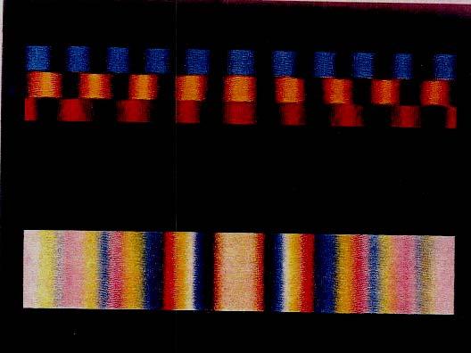
21 Colors in interferogram 22
22 Nulling Nulling interferometer (Bracewell) Star: Planet: Bright output Nulled output Stellar interferometer (Michelson) Star: Planet: mixed outputs 23
23 Theta 2 nulling 24
24 Theta 4 nulling 25
25 Multiplexing in the image plane 26

26 Multiplexing in the pupil plane FOV < Θ tel 27
27 Golden rule Output pupil must be a scaled version of input pupil in order to obtain a wide field of view. 28
28 Pupil densification 29
29 Instrumental effects: 1 30
30 Instrumental effects: 2 31
31 Filter and interferogram shapes K-band filter transmission K-band interferogram 32
32 Measuring visibility 33
33 Strehl: 1 Strehl ratio is approximately S = e -ϕ2 = exp(-ϕ 2 ) where ϕ is the rms phase error across a wavefront. Observed visibility is the product of 3 terms: V observed = S atmos S instrum V object Instrumental Strehl ratio is the product of many terms: S instrum = S servo S flat S align S diffraction S flux S overlap S vibration S window S polarization 34
34 Strehl: 2 Atmospheric variance, with tip-tilt removed by a servo system with bandwidth v/πd, is ϕ 2 = ( )(D/r 0 ) 5/3 (λ 0 /λ) 2 Wavefront flatness variance from mirror surfaces is ϕ 2 = ϕ ϕ n 2 Mirrors are often specified in terms of surface peak-to-valley where an empirical relation is PV = 5.5 RMS 35
35 Polarization and visibility S and P refer to the electric vector components perpendicular and parallel to the plane of incidence. For a curved mirror, these axes vary from point to point. 36
36 Visibility reduction factor 37
37 Single-mode fiber optics 38

38 Injecting starlight into a fiber 39

39 Integrated optics: 1 40
40 Integrated optics: 2 41
41 Image-plane Coronagraphs: a Very Quick Introduction 42


; Macintosh et")
42 Current ground-based coronagraph examples K~20 mag Bkgd objects 7 arcsec wand J~21 mag Bkgd object 20 arcsec radius circle Ref: McCarthy & Zuckerman (2004); Macintosh et al (2003) 43
43 aperture image mask Lyot stop detector Classical Coronagraph A(x) M(x) MA L*[MA] L(x)*[M(x) A(x)]~0 Ref.: Sivaramakrishnan et al., ApJ, 552, p.397, 2001; Kuchner A(u) u x x x M*Au L(u) u L[M*A] u x L(u) [M(u)*A(u)]~0 44
44 Band-limited (1 - sin x/x) mask Amplitude of on-axis star = 1 e i0 FT(1 - sin x/x) = delta(u) + rect(u) Convolution Lyot stop blocks bright edges Zero transmission of on-axis star 45

45 Image-plane coronagraph simulation 1st pupil 1st image with Airy rings mask, centered on star image 2nd pupil Lyot stop, blocks bright edges 2nd image, no star, bright planet Ref.: Pascal Borde
46 Perturbation #1: ripples and speckles 47
47 Phase ripple and speckles Suppose there is height error h(u) across the pupil, where h(u) = Σ n a n cos(2πnu/d) + b n sin(2πnu/d) = ripple The amplitude across the pupil is then A(u) = e ikh(u) 1 + ik[σ n a n cos(2πnu/d) + b n sin(2πnu/d)] In the image plane at angle α the amplitude will be A(α) = A(u) e ikαu du = δ(0) + (i/2) Σ n [(a n -ib n )δ(kα-kn) + [(a n +ib n )δ(kα+kn)] where we use K = 2π/D. The image intensity is then I(α) = δ(0) + (1/4) Σ n (a n2 +b n2 ) [δ(kα-kn) + δ(kα+kn)] = speckles at α = ±nλ/d If we add a deformable mirror (DM), then a n a n +A n and b n b n +B n Commanding A n =-a n and B n =-b n forces all speckles to zero. 48
48 Phase + amplitude ripple and speckles Suppose the height error h(u) across the pupil is complex, where h(u) = Σ n (a n +ia n ')cos(knu) + (b n +ib n ')sin(knu) = ripple i.e., we have both phase and amplitude ripples (= errors). The image intensity is then I(α) = δ(0) + (1/4) Σ n [(a n +b n ) 2 + (b n -a n ) 2 ] δ(kα+kn) + [(a n -b n ) 2 + (b n +a n ) 2 ] δ(kα-kn)] = speckles If we add a deformable mirror (DM), and command A n = -(a n -b n ) and B n = -(b n +a n ) Then we get I(α) = δ(0) + Σ n [(b n ) 2 + (a n ) 2 ] δ(kα+kn) bigger speckles + [ ] δ(kα-kn)] smaller (zero) speckles So in half the field of view we get no speckles, but in the other half we get stronger speckles. 49
49 Phase ripple and speckles Polishing errors on primary Phase ripples from primary mirror errors Pupil plane Speckles generated by 3 sinusoidal components of the polishing errors No DM: Image plane With DM: Image plane 50
50 So, we discussed these topics: 1. Thinking in terms of wavelets. 2. Calculating the interference of wavefronts for any optical system. 3. Learning about astrophysical vs instrumental effects. 4. A teaser about coronagraphs and speckles. 51
Exoplanets Direct imaging. Direct method of exoplanet detection. Direct imaging: observational challenges
 Black body flux (in units 10-26 W m -2 Hz -1 ) of some Solar System bodies as seen from 10 pc. A putative hot Jupiter is also shown. The planets have two peaks in their spectra. The short-wavelength peak
Wavefront Sensing using Polarization Shearing Interferometer. A report on the work done for my Ph.D. J.P.Lancelot
 Wavefront Sensing using Polarization Shearing Interferometer A report on the work done for my Ph.D J.P.Lancelot CONTENTS 1. Introduction 2. Imaging Through Atmospheric turbulence 2.1 The statistics of
Astronomical Techniques
 Astronomers use different techniques to extract information from the light that they detect with detectors Celestial objects emit light (different wavelengths) Telescopes are used to see these distant
Techniques for direct imaging of exoplanets
 Techniques for direct imaging of exoplanets Aglaé Kellerer Institute for Astronomy, Hawaii 1. Where lies the challenge? 2. Contrasts required for ground observations? 3. Push the contrast limit Recycle!
n The visual examination of the image of a point source is one of the most basic and important tests that can be performed.
 8.2.11 Star Test n The visual examination of the image of a point source is one of the most basic and important tests that can be performed. Interpretation of the image is to a large degree a matter of
Interference, Diffraction and Fourier Theory. ATI 2014 Lecture 02! Keller and Kenworthy
 Interference, Diffraction and Fourier Theory ATI 2014 Lecture 02! Keller and Kenworthy The three major branches of optics Geometrical Optics Light travels as straight rays Physical Optics Light can be
1. Give short answers to the following questions. a. What limits the size of a corrected field of view in AO?
 Astronomy 418/518 final practice exam 1. Give short answers to the following questions. a. What limits the size of a corrected field of view in AO? b. Describe the visibility vs. baseline for a two element,
Fully achromatic nulling interferometer (FANI) for high SNR exoplanet characterization
 for high SNR exoplanet characterization") Fully achromatic nulling interferometer (FANI) for high SNR exoplanet characterization François Hénault Institut de Planétologie et d Astrophysique de Grenoble Université Joseph Fourier Centre National
Fully achromatic nulling interferometer (FANI) for high SNR exoplanet characterization François Hénault Institut de Planétologie et d Astrophysique de Grenoble Université Joseph Fourier Centre National
Exoplanets Direct imaging. Direct method of exoplanet detection. Direct imaging: observational challenges
 Black body flux (in units 10-26 W m -2 Hz -1 ) of some Solar System bodies as seen from 10 pc. A putative hot Jupiter is also shown. The planets have two peaks in their spectra. The short-wavelength peak
Phys102 Lecture Diffraction of Light
 Phys102 Lecture 31-33 Diffraction of Light Key Points Diffraction by a Single Slit Diffraction in the Double-Slit Experiment Limits of Resolution Diffraction Grating and Spectroscopy Polarization References
Physics I : Oscillations and Waves Prof. S. Bharadwaj Department of Physics and Meteorology Indian Institute of Technology, Kharagpur
 Physics I : Oscillations and Waves Prof. S. Bharadwaj Department of Physics and Meteorology Indian Institute of Technology, Kharagpur Lecture - 21 Diffraction-II Good morning. In the last class, we had
Nature of Light Part 2
 Nature of Light Part 2 Fresnel Coefficients From Helmholts equation see imaging conditions for Single lens 4F system Diffraction ranges Rayleigh Range Diffraction limited resolution Interference Newton
Astronomy 203 practice final examination
 Astronomy 203 practice final examination Fall 1999 If this were a real, in-class examination, you would be reminded here of the exam rules, which are as follows: You may consult only one page of formulas
Optics Optical Testing and Testing Instrumentation Lab
 Optics 513 - Optical Testing and Testing Instrumentation Lab Lab #6 - Interference Microscopes The purpose of this lab is to observe the samples provided using two different interference microscopes --
Optics.
 Optics www.optics.rochester.edu/classes/opt100/opt100page.html Course outline Light is a Ray (Geometrical Optics) 1. Nature of light 2. Production and measurement of light 3. Geometrical optics 4. Matrix
Cheapest nuller in the World: Crossed beamsplitter cubes
 Cheapest nuller in the World: François Hénault Institut de Planétologie et d Astrophysique de Grenoble, Université Joseph Fourier, CNRS, B.P. 53, 38041 Grenoble France Alain Spang Laboratoire Lagrange,
1. Waves and Particles 2. Interference of Waves 3. Wave Nature of Light
 1. Waves and Particles 2. Interference of Waves 3. Wave Nature of Light 1. Double-Slit Eperiment reading: Chapter 22 2. Single-Slit Diffraction reading: Chapter 22 3. Diffraction Grating reading: Chapter
Waves Part III Electromagnetic waves
 Waves Part III Electromagnetic waves Electromagnetic (light) waves Transverse waves Transport energy (and momentum) Can travel through vacuum (!) and certain solids, liquids and gases Do not transport
Recent progress in SR interferometer
 Recent progress in SR interferometer -for small beam size measurement- T. Mitsuhashi, KEK Agenda 1. Brief introduction of beam size measurement through SR interferometry. 2. Theoretical resolution of interferometry
Webster Cash University of Colorado. X-ray Interferometry
 Webster Cash University of Colorado X-ray Interferometry Co-Investigators Steve Kahn - Columbia University Mark Schattenburg - MIT David Windt - Lucent (Bell-Labs) Outline of Presentation Science Potential
Astronomy. Optics and Telescopes
 Astronomy A. Dayle Hancock adhancock@wm.edu Small 239 Office hours: MTWR 10-11am Optics and Telescopes - Refraction, lenses and refracting telescopes - Mirrors and reflecting telescopes - Diffraction limit,
PRINCIPLES OF PHYSICAL OPTICS
 PRINCIPLES OF PHYSICAL OPTICS C. A. Bennett University of North Carolina At Asheville WILEY- INTERSCIENCE A JOHN WILEY & SONS, INC., PUBLICATION CONTENTS Preface 1 The Physics of Waves 1 1.1 Introduction
Optical/IR Observational Astronomy Telescopes I: Optical Principles. David Buckley, SAAO. 24 Feb 2012 NASSP OT1: Telescopes I-1
 David Buckley, SAAO 24 Feb 2012 NASSP OT1: Telescopes I-1 1 What Do Telescopes Do? They collect light They form images of distant objects The images are analyzed by instruments The human eye Photographic
Exam 3--PHYS 202--S10
 ame: Exam 3--PHYS 202--S0 Multiple Choice Identify the choice that best completes the statement or answers the question A person uses a convex lens that has a focal length of 25 cm to inspect a gem The
Application of Precision Deformable Mirrors to Space Astronomy
 Application of Precision Deformable Mirrors to Space Astronomy John Trauger, Dwight Moody Brian Gordon, Yekta Gursel (JPL) Mark Ealey, Roger Bagwell (Xinetics) Workshop on Innovative Designs for the Next
7. Telescopes: Portals of Discovery Pearson Education Inc., publishing as Addison Wesley
 7. Telescopes: Portals of Discovery Parts of the Human Eye pupil allows light to enter the eye lens focuses light to create an image retina detects the light and generates signals which are sent to the
AOL Spring Wavefront Sensing. Figure 1: Principle of operation of the Shack-Hartmann wavefront sensor
 AOL Spring Wavefront Sensing The Shack Hartmann Wavefront Sensor system provides accurate, high-speed measurements of the wavefront shape and intensity distribution of beams by analyzing the location and
How Giovanni s Balloon Borne Telescope Contributed to Today s Search for Life on Exoplanets
 How Giovanni s Balloon Borne Telescope Contributed to Today s Search for Life on Exoplanets Wesley A. Jet Propulsion Laboratory, California Ins:tute of Technology Symposium for Giovanni Fazio Harvard Smithsonian
The Nulling Coronagraph Using a Nulling Interferometer for Planet Detection in Visible Light with a Single Aperture Telescope
 Terrestrial Planet Finder The Nulling Coronagraph Using a Nulling Interferometer for Planet Detection in Visible Light with a Single Aperture Telescope Michael Shao, B. Martin Levine, Duncan Liu, J. Kent
PS210 - Optical Techniques. Section VI
 PS210 - Optical Techniques Section VI Section I Light as Waves, Rays and Photons Section II Geometrical Optics & Optical Instrumentation Section III Periodic and Non-Periodic (Aperiodic) Waves Section
Telescopes (Chapter 6)
") Telescopes (Chapter 6) Based on Chapter 6 This material will be useful for understanding Chapters 7 and 10 on Our planetary system and Jovian planet systems Chapter 5 on Light will be useful for understanding
Telescopes (Chapter 6) Based on Chapter 6 This material will be useful for understanding Chapters 7 and 10 on Our planetary system and Jovian planet systems Chapter 5 on Light will be useful for understanding
Probing the orbital angular momentum of light with a multipoint interferometer
 CHAPTER 2 Probing the orbital angular momentum of light with a multipoint interferometer We present an efficient method for probing the orbital angular momentum of optical vortices of arbitrary sizes.
Lecture PowerPoints. Chapter 24 Physics: Principles with Applications, 7 th edition Giancoli
 Lecture PowerPoints Chapter 24 Physics: Principles with Applications, 7 th edition Giancoli This work is protected by United States copyright laws and is provided solely for the use of instructors in teaching
PH 222-3A Spring 2010
 PH -3A Spring 010 Interference Lecture 6-7 Chapter 35 (Halliday/Resnick/Walker, Fundamentals of Physics 8 th edition) 1 Chapter 35 Interference The concept of optical interference is critical to understanding
PHY410 Optics Exam #3
 PHY410 Optics Exam #3 NAME: 1 2 Multiple Choice Section - 5 pts each 1. A continuous He-Ne laser beam (632.8 nm) is chopped, using a spinning aperture, into 500 nanosecond pulses. Compute the resultant
Metrology and Sensing
 Metrology and Sensing Lecture 5: Interferometry I 06--09 Herbert Gross Winter term 06 www.iap.uni-jena.de Preliminary Schedule No Date Subject Detailed Content 8.0. Introduction Introduction, optical measurements,
Phase-Referencing and the Atmosphere
 Phase-Referencing and the Atmosphere Francoise Delplancke Outline: Basic principle of phase-referencing Atmospheric / astrophysical limitations Phase-referencing requirements: Practical problems: dispersion
Design and Correction of optical Systems
 Design and Correction of optical Systems Part 10: Performance criteria 1 Summer term 01 Herbert Gross Overview 1. Basics 01-04-18. Materials 01-04-5 3. Components 01-05-0 4. Paraxial optics 01-05-09 5.
Radio Interferometry and Aperture Synthesis
 Radio Interferometry and Aperture Synthesis Phil gave a detailed picture of homodyne interferometry Have to combine the light beams physically for interference Imposes many stringent conditions on the
The science of light. P. Ewart
 The science of light P. Ewart Oxford Physics: Second Year, Optics Parallel reflecting surfaces t images source Extended source path difference xcos 2t=x Fringes localized at infinity Circular fringe constant
Christian Marois Lawrence Livermore National Laboratory
 Christian Marois Lawrence Livermore National Laboratory -Detecting Exoplanets -Speckle noise attenuation techniques with specialized observation schemes and post-processing algorithms -Current On-sky performances
Optical/IR Observational Astronomy Telescopes I: Telescope Basics. David Buckley, SAAO
 David Buckley, SAAO 27 Feb 2012 1 Some other Telescope Parameters 1. Plate Scale This defines the scale of an image at the telescopes focal surface For a focal plane, with no distortion, this is just related
UNIT-5 EM WAVES UNIT-6 RAY OPTICS
 UNIT-5 EM WAVES 2 Marks Question 1. To which regions of electromagnetic spectrum do the following wavelengths belong: (a) 250 nm (b) 1500 nm 2. State any one property which is common to all electromagnetic
Lecture 9: Indirect Imaging 2. Two-Element Interferometer. Van Cittert-Zernike Theorem. Aperture Synthesis Imaging. Outline
 Lecture 9: Indirect Imaging 2 Outline 1 Two-Element Interferometer 2 Van Cittert-Zernike Theorem 3 Aperture Synthesis Imaging Cygnus A at 6 cm Image courtesy of NRAO/AUI Very Large Array (VLA), New Mexico,
LC circuit: Energy stored. This lecture reviews some but not all of the material that will be on the final exam that covers in Chapters
 Disclaimer: Chapter 29 Alternating-Current Circuits (1) This lecture reviews some but not all of the material that will be on the final exam that covers in Chapters 29-33. LC circuit: Energy stored LC
Chapter 6 SCALAR DIFFRACTION THEORY
 Chapter 6 SCALAR DIFFRACTION THEORY [Reading assignment: Hect 0..4-0..6,0..8,.3.3] Scalar Electromagnetic theory: monochromatic wave P : position t : time : optical frequency u(p, t) represents the E or
Spectroscopy. Stephen Eikenberry (U. Florida) Dunlap Institute Summer School 25 July 2018
 Dunlap Institute Summer School 25 July 2018") Spectroscopy Stephen Eikenberry (U. Florida) Dunlap Institute Summer School 25 July 2018 Observational Astronomy What? Astronomy gathers the vast majority of its information from the LIGHT emitted by astrophysical
Spectroscopy Stephen Eikenberry (U. Florida) Dunlap Institute Summer School 25 July 2018 Observational Astronomy What? Astronomy gathers the vast majority of its information from the LIGHT emitted by astrophysical
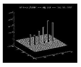
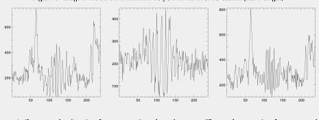
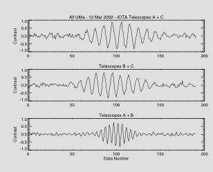
Characterizing Closure-phase Measurements at IOTA
 Characterizing Closure-phase Measurements at IOTA Ragland, S. 1,2,3, Traub, W. 1, Berger, J.-P. 4, Millan-Gabet, R. 5, Monnier, J. D. 6, Pedretti, E. 6, Schloerb, F. P. 7, Carleton, N. P. 1, Haguenauer,
OPSE FINAL EXAM Fall 2016 YOU MUST SHOW YOUR WORK. ANSWERS THAT ARE NOT JUSTIFIED WILL BE GIVEN ZERO CREDIT.
 CLOSED BOOK. Equation Sheet is provided. YOU MUST SHOW YOUR WORK. ANSWERS THAT ARE NOT JUSTIFIED WILL BE GIVEN ZERO CREDIT. ALL NUMERICAL ANSERS MUST HAVE UNITS INDICATED. (Except dimensionless units like
Engineering Physics 1 Prof. G.D. Vermaa Department of Physics Indian Institute of Technology-Roorkee
 Engineering Physics 1 Prof. G.D. Vermaa Department of Physics Indian Institute of Technology-Roorkee Module-04 Lecture-02 Diffraction Part - 02 In the previous lecture I discussed single slit and double
Astr 2310 Thurs. March 3, 2016 Today s Topics
 Astr 2310 Thurs. March 3, 2016 Today s Topics Chapter 6: Telescopes and Detectors Optical Telescopes Simple Optics and Image Formation Resolution and Magnification Invisible Astronomy Ground-based Radio
Part 1 - Basic Interferometers for Optical Testing
 Part 1 - Basic Interferometers for Optical Testing Two Beam Interference Fizeau and Twyman-Green interferometers Basic techniques for testing flat and spherical surfaces Mach-Zehnder Zehnder,, Scatterplate
Lecture notes 5: Diffraction
 Lecture notes 5: Diffraction Let us now consider how light reacts to being confined to a given aperture. The resolution of an aperture is restricted due to the wave nature of light: as light passes through
Overview: Astronomical Spectroscopy
 Overview: Astronomical Spectroscopy or How to Start Thinking Creatively about Measuring the Universe Basic Spectrograph Optics Objective Prism Spectrometers - AESoP Slit Spectrometers Spectrometers for
Prac%ce Quiz 8. These are Q s from old quizzes. I do not guarantee that the Q s on this year s quiz will be the same, or even similar.
 Prac%ce Quiz 8 These are Q s from old quizzes. I do not guarantee that the Q s on this year s quiz will be the same, or even similar. A laser beam shines vertically upwards. What laser power is needed
Physical Optics. Lecture 2: Diffraction Herbert Gross.
 Physical Optics Lecture : Diffraction 018-04-18 Herbert Gross www.iap.uni-jena.de Physical Optics: Content No Date Subject Ref Detailed Content 1 11.04. Wave optics G Complex fields, wave equation, k-vectors,
Ay 20 Basic Astronomy and the Galaxy Problem Set 2
 Ay 20 Basic Astronomy and the Galaxy Problem Set 2 October 19, 2008 1 Angular resolutions of radio and other telescopes Angular resolution for a circular aperture is given by the formula, θ min = 1.22λ
Chapter 36, example problems:
 Chapter 6, example problems: (6.0) Light wave with electric field E y (x, t) = E max sin [(.20 0 7 m ) x ω t] passes through a slit. First dark band at ±2.6 from the center of the diffraction pattern.
Extreme Optics and The Search for Earth-Like Planets
 Extreme Optics and The Search for Earth-Like Planets Robert J. Vanderbei November 21, 27 ORFE 522 Fun (Pre-Thanksgiving) Lecture Work supported by ONR and NASA/JPL http://www.princeton.edu/ rvdb ABSTRACT
Metrology and Sensing
 Metrology and Sensing Lecture 5: Interferometry I 08--6 Herbert Gross Winter term 08 www.iap.uni-jena.de Schedule Optical Metrology and Sensing 08 No Date Subject Detailed Content 6.0. Introduction Introduction,
AST 101 Intro to Astronomy: Stars & Galaxies
 AST 101 Intro to Astronomy: Stars & Galaxies Telescopes Mauna Kea Observatories, Big Island, HI Imaging with our Eyes pupil allows light to enter the eye lens focuses light to create an image retina detects
Palomar Testbed Interferometer (PTI) & Keck Interferometer (KI) Mark Colavita 7/29/2005 Michelson Summer School Pasadena, CA
 & Keck Interferometer (KI) Mark Colavita 7/29/2005 Michelson Summer School Pasadena, CA") Palomar Testbed Interferometer (PTI) & Keck Interferometer (KI) Mark Colavita 7/29/2005 Michelson Summer School Pasadena, CA PTI as seen from the catwalk of the 200 telescope Michelson Interferometer stellar
Palomar Testbed Interferometer (PTI) & Keck Interferometer (KI) Mark Colavita 7/29/2005 Michelson Summer School Pasadena, CA PTI as seen from the catwalk of the 200 telescope Michelson Interferometer stellar
Some Topics in Optics
 Some Topics in Optics The HeNe LASER The index of refraction and dispersion Interference The Michelson Interferometer Diffraction Wavemeter Fabry-Pérot Etalon and Interferometer The Helium Neon LASER A
OPSE FINAL EXAM Fall 2015 YOU MUST SHOW YOUR WORK. ANSWERS THAT ARE NOT JUSTIFIED WILL BE GIVEN ZERO CREDIT.
 CLOSED BOOK. Equation Sheet is provided. YOU MUST SHOW YOUR WORK. ANSWERS THAT ARE NOT JUSTIFIED WILL BE GIVEN ZERO CREDIT. ALL NUMERICAL ANSERS MUST HAVE UNITS INDICATED. (Except dimensionless units like
Optical/IR Observational Astronomy Telescopes I: Telescope Basics. David Buckley, SAAO
 David Buckley, SAAO 17 Feb 2010 1 Some other Telescope Parameters 1. Plate Scale This defines the scale of an image at the telescopes focal surface For a focal plane, with no distortion, this is just related
Metrology and Sensing
 Metrology and Sensing Lecture 5: Interferometry I 017-11-16 Herbert Gross Winter term 017 www.iap.uni-jena.de Preliminary Schedule No Date Subject Detailed Content 1 19.10. Introduction Introduction, optical
Topic 4 &11 Review Waves & Oscillations
 Name: Date: Topic 4 &11 Review Waves & Oscillations 1. A source produces water waves of frequency 10 Hz. The graph shows the variation with horizontal position of the vertical displacement of the surface
Chapter 35. Interference
 Chapter 35 Interference The concept of optical interference is critical to understanding many natural phenomena, ranging from color shifting in butterfly wings to intensity patterns formed by small apertures.
ADAPTIVE PHASE MASK CORONAGRAPH
 Florence, Italy. May 2013 ISBN: 978-88-908876-0-4 DOI: 10.12839/AO4ELT3.13183 ADAPTIVE PHASE MASK CORONAGRAPH Pierre Haguenauer 1,a, Pierre Bourget 1, Dimitri Mawet 1, and Nicolas Schuhler 1 1 European
Speckles and adaptive optics
 Chapter 9 Speckles and adaptive optics A better understanding of the atmospheric seeing and the properties of speckles is important for finding techniques to reduce the disturbing effects or to correct
arxiv:astro-ph/ v1 28 May 2003
 Scientific Frontiers in Research on Extrasolar Planets ASP Conference Series, Vol. 294, 2003 D. Deming and S. Seager, eds. Terrestrial Planet Finding with a Visible Light Coronagraph arxiv:astro-ph/0305522v1
Physics 1302, Exam 3 Review
 c V Andersen, 2006 1 Physics 1302, Exam 3 Review The following is a list of things you should definitely know for the exam, however, the list is not exhaustive. You are responsible for all the material
An Example of Telescope Resolution
 An Example of Telescope Resolution J. Kielkopf September 23, 2012 1 Principles Light leaves a distant source with the properties of a spherical wave. That is, the phase of the wave is constant on the surface
An Introduction to. Adaptive Optics. Presented by. Julian C. Christou Gemini Observatory
 An Introduction to Adaptive Optics Presented by Julian C. Christou Gemini Observatory Gemini North in action Turbulence An AO Outline Atmospheric turbulence distorts plane wave from distant object. How
2.71. Final examination. 3 hours (9am 12 noon) Total pages: 7 (seven) PLEASE DO NOT TURN OVER UNTIL EXAM STARTS PLEASE RETURN THIS BOOKLET
 Total pages: 7 (seven) PLEASE DO NOT TURN OVER UNTIL EXAM STARTS PLEASE RETURN THIS BOOKLET") 2.71 Final examination 3 hours (9am 12 noon) Total pages: 7 (seven) PLEASE DO NOT TURN OVER UNTIL EXAM STARTS Name: PLEASE RETURN THIS BOOKLET WITH YOUR SOLUTION SHEET(S) MASSACHUSETTS INSTITUTE OF TECHNOLOGY
2.71 Final examination 3 hours (9am 12 noon) Total pages: 7 (seven) PLEASE DO NOT TURN OVER UNTIL EXAM STARTS Name: PLEASE RETURN THIS BOOKLET WITH YOUR SOLUTION SHEET(S) MASSACHUSETTS INSTITUTE OF TECHNOLOGY
Name Final Exam May 1, 2017
 Name Final Exam May 1, 217 This test consists of five parts. Please note that in parts II through V, you can skip one question of those offered. Some possibly useful formulas appear below. Constants, etc.
Electricity & Optics
 Physics 24100 Electricity & Optics Lecture 26 Chapter 33 sec. 1-4 Fall 2017 Semester Professor Koltick Interference of Light Interference phenomena are a consequence of the wave-like nature of light Electric
DIFFRACTION AND INTERFERENCE
 DIFFRACTION AND INTERFERENCE We now turn to a consideration of what happens when two light waves interact with one another. We assume that the intensities are low enough that the disturbances add vectorially.
Exoplanet Detection and Characterization with Mid-Infrared Interferometry
 Exoplanet Detection and Characterization with Mid-Infrared Interferometry Rachel Akeson NASA Exoplanet Science Institute With thanks to Peter Lawson for providing material Sagan Workshop July 21, 2009
Why Use a Telescope?
 1 Why Use a Telescope? All astronomical objects are distant so a telescope is needed to Gather light -- telescopes sometimes referred to as light buckets Resolve detail Magnify an image (least important
Adaptive Optics for the Giant Magellan Telescope. Marcos van Dam Flat Wavefronts, Christchurch, New Zealand
 Adaptive Optics for the Giant Magellan Telescope Marcos van Dam Flat Wavefronts, Christchurch, New Zealand How big is your telescope? 15-cm refractor at Townsend Observatory. Talk outline Introduction
arxiv: v1 [astro-ph.im] 10 Oct 2017
![arxiv: v1 [astro-ph.im] 10 Oct 2017](/thumbs/76/73487319.jpg "arxiv: v1 [astro-ph.im] 10 Oct 2017") Experimental parametric study of the Self-Coherent Camera arxiv:1710.03520v1 [astro-ph.im] 10 Oct 2017 Johan Mazoyer a, Pierre Baudoz a, Marion Mas ab, Gerard Rousset a,raphaël Galicher cd a LESIA, Observatoire
Experimental parametric study of the Self-Coherent Camera arxiv:1710.03520v1 [astro-ph.im] 10 Oct 2017 Johan Mazoyer a, Pierre Baudoz a, Marion Mas ab, Gerard Rousset a,raphaël Galicher cd a LESIA, Observatoire
High Contrast Imaging: Direct Detection of Extrasolar Planets
 High Contrast Imaging: Direct Detection of Extrasolar Planets James R. Graham University of Toronto Dunlap Institute and Astronomy & Astrophysics September 16, 2010 Exoplanet Science How and where to planets
Edward S. Rogers Sr. Department of Electrical and Computer Engineering. ECE426F Optical Engineering. Final Exam. Dec. 17, 2003.
 Edward S. Rogers Sr. Department of Electrical and Computer Engineering ECE426F Optical Engineering Final Exam Dec. 17, 2003 Exam Type: D (Close-book + one 2-sided aid sheet + a non-programmable calculator)
x Contents Segmented Mirror Telescopes Metal and Lightweight Mirrors Mirror Polishing
 Contents 1 Fundamentals of Optical Telescopes... 1 1.1 A Brief History of Optical Telescopes.................... 1 1.2 General Astronomical Requirements..................... 6 1.2.1 Angular Resolution.............................
JRE Group of Institutions ASSIGNMENT # 1 Special Theory of Relativity
 ASSIGNMENT # 1 Special Theory of Relativity 1. What was the objective of conducting the Michelson-Morley experiment? Describe the experiment. How is the negative result of the experiment interpreted? 2.
Week 7: Interference
 Week 7: Interference Superposition: Till now we have mostly discusssed single waves. While discussing group velocity we did talk briefly about superposing more than one wave. We will now focus on superposition
Telescopes: Portals of Discovery
 Telescopes: Portals of Discovery How do light and matter interact? Emission Absorption Transmission Transparent objects transmit light Opaque objects block (absorb) light Reflection or Scattering Reflection
The Diffraction Grating
 The Diffraction Grating If one extends the double slit to large number of slits very closely spaced, one gets what is called a diffraction grating. d sin θ. Maxima are still at d sin θ m = mλ, m = 0, 1,
Michelson Interferometer
 Michelson Interferometer Objective Determination of the wave length of the light of the helium-neon laser by means of Michelson interferometer subsectionprinciple and Task Light is made to produce interference
Measurements in Optics for Civil Engineers
 Measurements in Optics for Civil Engineers I. FOCAL LENGTH OF LENSES The behavior of simplest optical devices can be described by the method of geometrical optics. For convex or converging and concave
Lecture 9: Introduction to Diffraction of Light
 Lecture 9: Introduction to Diffraction of Light Lecture aims to explain: 1. Diffraction of waves in everyday life and applications 2. Interference of two one dimensional electromagnetic waves 3. Typical
Chapter 6 Telescopes: Portals of Discovery
 Chapter 6 Telescopes: Portals of Discovery 6.1 Eyes and Cameras: Everyday Light Sensors Our goals for learning: How does your eye form an image? How do we record images? How does your eye form an image?
31. Diffraction: a few important illustrations
 31. Diffraction: a few important illustrations Babinet s Principle Diffraction gratings X-ray diffraction: Bragg scattering and crystal structures A lens transforms a Fresnel diffraction problem into a
Physics 116. Nov 3, Lecture 21 Wave optics. R. J. Wilkes 11/3/11 1
 Physics 116 Lecture 21 Wave optics Nov 3, 2011 R. J. Wilkes Email: ph116@u.washington.edu 11/3/11 1 Announcements 3 clickers have quiz data logged, but no registration: 622961 649314 614235 If one of these
Designing a Space Telescope to Image Earth-like Planets
 Designing a Space Telescope to Image Earth-like Planets Robert J. Vanderbei Rutgers University December 4, 2002 Page 1 of 28 Member: Princeton University/Ball Aerospace TPF Team http://www.princeton.edu/
High-contrast Coronagraph Development in China for Direct Imaging of Extra-solar Planets
 High-contrast Coronagraph Development in China for Direct Imaging of Extra-solar Planets Jiangpei Dou 1, Deqing Ren 1,2, Yongtian Zhu 1, Xi Zhang 1 1 Astronomical Observatories/Nanjing Institute of Astronomical
High Dynamic Range and the Search for Planets
 Brown Dwarfs IAU Symposium, Vol. 211, 2003 E. L. Martín, ed. High Dynamic Range and the Search for Planets A. T. Tokunaga, C. Ftaclas, J. R. Kuhn, and P. Baudoz Institute for Astronomy, Univ. of Hawaii,
Light as a Transverse Wave.
 Waves and Superposition (Keating Chapter 21) The ray model for light (i.e. light travels in straight lines) can be used to explain a lot of phenomena (like basic object and image formation and even aberrations)
Problem Solving. radians. 180 radians Stars & Elementary Astrophysics: Introduction Press F1 for Help 41. f s. picture. equation.
 Problem Solving picture θ f = 10 m s =1 cm equation rearrange numbers with units θ factors to change units s θ = = f sinθ fθ = s / cm 10 m f 1 m 100 cm check dimensions 1 3 π 180 radians = 10 60 arcmin