09/29/2009 Reading: Hambley Chapter 5 and Appendix A
|
|
|
- Marcus Manning
- 5 years ago
- Views:
Transcription
1 EE40 Lec 10 Complex Numbers and Phasors Prof. Nathan Cheung 09/29/2009 Reading: Hambley Chapter 5 and Appendix A Slide 1
2 OUTLINE Phasors as notation for Sinusoids Arithmetic with Complex Numbers Complex impedances Circuit analysis using complex impedances Dervative/Integration as multiplication/division Phasor Relationship for Circuit Elements Slide 2
3 Types of Circuit Excitation Linear Time- Invariant Circuit Steady-State Excitation (DC Steady-State) Linear Time- Invariant Circuitit Sinusoidal (Single- Frequency) Excitation AC Steady-State Step Excitation Digital Pulse Source Linear Time- Invariant Circuit OR Linear Time- Invariant Circuit Transient Excitations Slide 3
4 Sinusoids vt () V cos ωt θ Amplitude: V ( ) M M Angular frequency: ω 2π f Radians/sec Phase angle: θ Frequency: f 1/T Unit: 1/sec or Hz Period: T Time necessary to go through one cycle Slide 4
5 Sinusoids What is the amplitude, period, frequency, and radian frequency of this sinusoid? id? Slide 5
6 Sinusoidal Sources Create Too Much Algebra Guess a solution x P ( t) Asin( wt) B cos( wt) x dxp ( t) ( t) τ FA sin( wt) FB cos( wt) dt P d ( Asin( wt ) B cos( wt )) ( Asin( i( wt ) B cos( wt )) τ FA sin( i( wt ) FB cos( wt ) dt ( A τb FA)sin( wt) ( B τa FB )cos( wt) ( A τb FA ) 0 ( B τa F ) 0 B F τ A F A B τ 2 1 τ F A F B τ 2 1 Phasors s (vectors that rotate in the complex plane) are a clever alternative. B 0 Slide 6
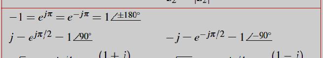
7 y Complex Numbers (1) imaginary i x is the real part axis j ( 1) θ real x axis Rectangular Coordinates Z x jy Polar Coordinates: Z z θ Exponential Form: y is the imaginary part z is the magnitude θ is the phase x z cosθ 2 z x π j θ j θ j Z Z e ze 2 y Z z(cosθ jsin θ ) 2 j0 1 1e 1 0 j 1e 1 90 y z sinθ θ tan 1 y x Slide 7
8 Complex Numbers (2) Euler s Identities e cosθ e sinθ e jθ jθ jθ e 2 e 2 j jθ jθ cosθ jsinθ j 2 2 e θ cos θ sin θ 1 Exponential Form of a complex number Z j j θ θ Z e ze z θ Slide 8
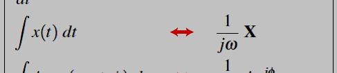
9 Arithmetic With Complex Numbers To compute phasor voltages and currents, we need to be able to perform computation with complex numbers. Addition Subtraction ti Multiplication Division (And later use multiplication by jω to replace Differentiation Integration Slide 9
10 Addition Addition is most easily performed in rectangular coordinates: A x jy B z jw A B (x z) j(y w) A B Imaginary Axis B A Real Axis Slide 10
11 Subtraction Subtraction is most easily performed in rectangular coordinates: A x jy B z jw A - B (x - z) j(y - w) Imaginary Axis B A A - B Real Axis Slide 11
12 Multiplication Multiplication is most easily performed in polar coordinates: A A M θ B B M φ A B (A M B M ) (θ φ) A B Imaginary Axis B A Real Axis Slide 12
13 Division Division is most easily performed in polar coordinates: A A M θ B B M φ A / B (A M / B M ) (θ φ) Imaginary Axis B A A / B Real Axis Slide 13
14 Arithmetic Operations of Complex Numbers Add and Subtract: it is easiest to do this in rectangular format Add/subtract the real and imaginary parts separately Multiply and Divide: it is easiest to do this in exponential/polar format Multiply (divide) the magnitudes Add (subtract) the phases Z Z Z Z Z 1 jθ1 ze 1 z1 θ1 z1 cos θ1 jz1 sin θ1 jθ 2 ze z θ z cosθ jz sinθ Z 2 ( z 1 cos θ 1 z 2 cos θ 2 ) j ( z 1 sin θ 1 z 2 sin θ 2 ) Z ( z cosθ z cos θ ) j( z sinθ z sin θ ) j( θ1 θ2) ( ) ( ) ( θ θ ) Z z z e z z j( θ θ ) 2 z1 z2 e ( z1/ z2) ( θ1 θ2) 1 2 Z / Z ( / ) 1 Slide 14


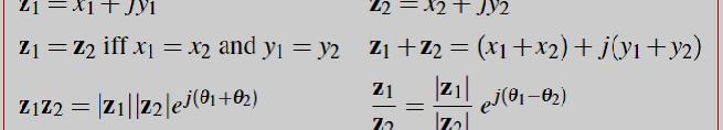
15 Summary of Complex Numbers Slide 15
16 Phasor: Rotating Complex Vector { jφ jwt} ( j ωt Ve e Re Ve ) v( t) V cos( ωt φ) Re Imaginary Axis Phasor Rotates at uniform angular velocity ωt V cos(ωtφ) Real Axis The head start angle is φ. Slide 16
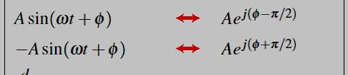
17 Phasors and Complex Exponentials A sinusoid can be described using a complex exponential: e jωt cos ωt j sin ωt So, v(t) V M cos (ωt θ) V M Re[e j (ωt θ) ] The phasor of v(t) is given by: V V M θ Slide 17
18 Sinusoids, Complex Exponentials, Phasors Sinusoid: z cos (ωtθ) Complex exponential: Phasor: Ae jωt z e j(ωtθ) V z θ Slide 18


19 Sinusoids <--> Phasors Slide 19
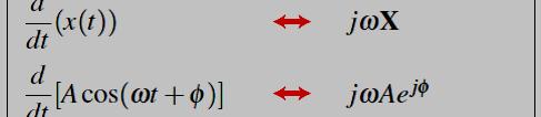
20 Complex Exponentials Complex Exponentials provide the link between time functions and phasors. Allow dervatives and integrals to be replaced by multiplying or dividing by jω make solving for AC steady state simple algebra with complex numbers. Phasors allow us to express current-voltage relationships for inductors and capacitors much like we express the current-voltage relationship for a resistor. Slide 20
21 Complex Impedance AC steady-state analysis using phasors allows us to express the relationship between current and voltage using a formula that looks likes Ohm s law: V IZ Z is called impedance. Slide 21
22 I-V Relationship for a Capacitor i(t) C v(t) () - i ( t ) C dv( t) dt Suppose that v(t) is a sinusoid: v(t) Re{V M e j(ωtθ) } Find i(t). Slide 22
23 Capacitor i(t) i(t) C v(t ) dv( t) i ( t ) C dt - V j( ωt θ) j( ωt θ) vt () Vcos( ωt θ) 2 e e dv () t CV d j ( ω t θ ) j ( ω t θ ) CV j ( ω t θ ) j ( ω t θ ) it () C e e j e e dt 2 dt ω 2 ωcv e j( ωt θ) e j( ωt θ) π ω CV sin( ω t θ) ω CV cos( ω t θ ) 2 j 2 Z c V V θ V π 1 π 1 1 ( θ θ ) ( ) j I π ωcv 2 ωc 2 ωc jωc I θ 2 Slide 23
24 Capacitor Impedance i(t) C v(t - ) i( t) dv( t) C dt Phasor definition ω θ θ j( ωt θ) vt () Vcos( t ) Re Ve V V j ( ωt θ ) dv() t de j( ωt θ) it ( ) C Re CV Re jωcve I θ dt dt I V V θ V 1 Note: j ( e Zc ( θ θ) jπ/2 ) is lumped into the amplitude expression here I I θ jωcv jωc Slide 24
25 Inductor Impedance i(t) L v(t) () - v ( t ) L di( t) dt V jωl I Slide 25
26 lead Capacitor: I leads V by 90 o Inductor: V leads I by 90 o Voltage 7cos( ω t) 7 0 inductor current π π 7sin( ω t ) 7cos( ω t ) Behind 2 0 t capacitor current π π 7sin( ωt) 7cos( ωt ) Slide 26
27 RLC Complex Impedances Slide 27
28 Circuit Analysis Using Complex Impedances Real-time KVL v () t v () t v () t ( ω θ ) ( ω θ ) ( ω θ ) V cos t V cos t V cos t j 1 2 ( 3 ) ( t ) j ( t Re ) j t Ve ω θ 1 Ve ω θ 2 Ve ω θ 3 0 Phasor Form KVL Ve Ve Ve θ VVV 0 j( θ 1) j( 2 ) j( 3 ) 1 θ Phasor Form KCL I 1I 2 I3 0 Use complex impedances for inductors and capacitors and follow same analysis as in chap 2 of Hambley. Slide 28
29 Example : Voltage Divider R10 k Ω v ( ) ( ) t 10cos 2π60t - C1 µf _ v c ( t )? 1. Source Phasor jφ V V0 e 10 f 60 ω 2π 60 φ π 2. Complex impedance V 0 10 Z R 10 4 Ω, Z C 1 jωc 1 j120π 10 6 Slide 29
30 Example : Voltage Divider cont. () t 10cos( 2π t) v 60 R10 k Ω - C1 µf _ c ( t )? ω 2π 60 v c φ 0 φ0 V π V 3. Use KVL or voltage divider id formula c Z C 1 6 Z C j120 π V 10 tan (1.2 π ) Z 1 1 j R 4 π 10 1 ( 1.2π) 6 j120π Change phasor back to actual signal ( ) ( o t 2.56 cos 120 π t 75 ) v c 75 Slide 30
31 Example: Thevenin Equivalent Circuit Sinusoidal Source V C R L a Find the Thevenin equivalent ckt. Z TH a b 1. Thevenin impedance by shorting the source 1/jωC a R jωl b Z TH Z C R // Z R // Z jωlr jωl ω V TH L 2 LCR b 2. Thevenin voltage using voltage divider Z// VTH V 1 Z// jωc where Slide 31 Z // jωlr R jωl
32 Example : Voltage Divider using Polar Coordinates 20kΩ 0 10V 0 V C kΩ -90 Now use the voltage divider to find V C : V C V C 2.65kΩ V k Ω k Ω V Note: polar co-ordinate better only for multiply l and divide Slide 32
33 Example: Parallel Impedance 5mA µF 1kΩ V Find v(t) for ω2π mA 0 -j530kω 1kΩ V - Slide 33
34 Example: Parallel Impedance cont. 5mA 0 Z eq V Z eq Z eq ( j530) j Ω V IZ 5mA Ω eq V 2.34V v( t) 2.34V cos(2π 3000t 62.1 ) Slide 34
35 Example : Superposition v C ( t)? C - I ( t ) ( ) I sin ω t R L I ( t ) I cos ( ω t ) I1 1 ω1 1. Two sources superposition 2. For each source use phasors ( analyzed directly or using source transformation) 3. Sum up the results Note: The two sources have different frequencies. The impedance will have different values for the different sources! Slide 35
EE100Su08 Lecture #11 (July 21 st 2008)
") EE100Su08 Lecture #11 (July 21 st 2008) Bureaucratic Stuff Lecture videos should be up by tonight HW #2: Pick up from office hours today, will leave them in lab. REGRADE DEADLINE: Monday, July 28 th 2008,
EE100Su08 Lecture #11 (July 21 st 2008) Bureaucratic Stuff Lecture videos should be up by tonight HW #2: Pick up from office hours today, will leave them in lab. REGRADE DEADLINE: Monday, July 28 th 2008,
Phasors: Impedance and Circuit Anlysis. Phasors
 Phasors: Impedance and Circuit Anlysis Lecture 6, 0/07/05 OUTLINE Phasor ReCap Capacitor/Inductor Example Arithmetic with Complex Numbers Complex Impedance Circuit Analysis with Complex Impedance Phasor
EE292: Fundamentals of ECE
 EE292: Fundamentals of ECE Fall 2012 TTh 10:00-11:15 SEB 1242 Lecture 18 121025 http://www.ee.unlv.edu/~b1morris/ee292/ 2 Outline Review RMS Values Complex Numbers Phasors Complex Impedance Circuit Analysis
Sinusoids and Phasors
 CHAPTER 9 Sinusoids and Phasors We now begins the analysis of circuits in which the voltage or current sources are time-varying. In this chapter, we are particularly interested in sinusoidally time-varying
Electric Circuit Theory
 Electric Circuit Theory Nam Ki Min nkmin@korea.ac.kr 010-9419-2320 Chapter 11 Sinusoidal Steady-State Analysis Nam Ki Min nkmin@korea.ac.kr 010-9419-2320 Contents and Objectives 3 Chapter Contents 11.1
Chapter 9 Objectives
 Chapter 9 Engr8 Circuit Analysis Dr Curtis Nelson Chapter 9 Objectives Understand the concept of a phasor; Be able to transform a circuit with a sinusoidal source into the frequency domain using phasor
Circuit Analysis-III. Circuit Analysis-II Lecture # 3 Friday 06 th April, 18
 Circuit Analysis-III Sinusoids Example #1 ü Find the amplitude, phase, period and frequency of the sinusoid: v (t ) =12cos(50t +10 ) Signal Conversion ü From sine to cosine and vice versa. ü sin (A ± B)
Name: Lab: M8 M2 W8 Th8 Th11 Th2 F8. cos( θ) = cos(θ) sin( θ) = sin(θ) sin(θ) = cos. θ (radians) θ (degrees) cos θ sin θ π/6 30
 = cos(θ) sin( θ) = sin(θ) sin(θ) = cos. θ (radians) θ (degrees) cos θ sin θ π/6 30") Name: Lab: M8 M2 W8 Th8 Th11 Th2 F8 Trigonometric Identities cos(θ) = cos(θ) sin(θ) = sin(θ) sin(θ) = cos Cosines and Sines of common angles Euler s Formula θ (radians) θ (degrees) cos θ sin θ 0 0 1 0
Name: Lab: M8 M2 W8 Th8 Th11 Th2 F8 Trigonometric Identities cos(θ) = cos(θ) sin(θ) = sin(θ) sin(θ) = cos Cosines and Sines of common angles Euler s Formula θ (radians) θ (degrees) cos θ sin θ 0 0 1 0
Chapter 10: Sinusoids and Phasors
 Chapter 10: Sinusoids and Phasors 1. Motivation 2. Sinusoid Features 3. Phasors 4. Phasor Relationships for Circuit Elements 5. Impedance and Admittance 6. Kirchhoff s Laws in the Frequency Domain 7. Impedance
EE292: Fundamentals of ECE
 EE292: Fundamentals of ECE Fall 2012 TTh 10:00-11:15 SEB 1242 Lecture 20 121101 http://www.ee.unlv.edu/~b1morris/ee292/ 2 Outline Chapters 1-3 Circuit Analysis Techniques Chapter 10 Diodes Ideal Model
Sinusoidal Steady State Analysis (AC Analysis) Part I
 Part I") Sinusoidal Steady State Analysis (AC Analysis) Part I Amin Electronics and Electrical Communications Engineering Department (EECE) Cairo University elc.n102.eng@gmail.com http://scholar.cu.edu.eg/refky/
Sinusoidal Steady State Analysis (AC Analysis) Part I Amin Electronics and Electrical Communications Engineering Department (EECE) Cairo University elc.n102.eng@gmail.com http://scholar.cu.edu.eg/refky/
Frequency Response. Re ve jφ e jωt ( ) where v is the amplitude and φ is the phase of the sinusoidal signal v(t). ve jφ
 where v is the amplitude and φ is the phase of the sinusoidal signal v(t). ve jφ") 27 Frequency Response Before starting, review phasor analysis, Bode plots... Key concept: small-signal models for amplifiers are linear and therefore, cosines and sines are solutions of the linear differential
27 Frequency Response Before starting, review phasor analysis, Bode plots... Key concept: small-signal models for amplifiers are linear and therefore, cosines and sines are solutions of the linear differential
Phasor Diagram. Figure 1: Phasor Diagram. A φ. Leading Direction. θ B. Lagging Direction. Imag. Axis Complex Plane. Real Axis
 1 16.202: PHASORS Consider sinusoidal source i(t) = Acos(ωt + φ) Using Eulers Notation: Acos(ωt + φ) = Re[Ae j(ωt+φ) ] Phasor Representation of i(t): = Ae jφ = A φ f v(t) = Bsin(ωt + ψ) First convert the
Name (print): Lab (circle): W8 Th8 Th11 Th2 F8. θ (radians) θ (degrees) cos θ sin θ π/ /2 1/2 π/4 45 2/2 2/2 π/3 60 1/2 3/2 π/
: Lab (circle): W8 Th8 Th11 Th2 F8. θ (radians) θ (degrees) cos θ sin θ π/ /2 1/2 π/4 45 2/2 2/2 π/3 60 1/2 3/2 π/") Name (print): Lab (circle): W8 Th8 Th11 Th2 F8 Trigonometric Identities ( cos(θ) = cos(θ) sin(θ) = sin(θ) sin(θ) = cos θ π ) 2 Cosines and Sines of common angles Euler s Formula θ (radians) θ (degrees)
Name (print): Lab (circle): W8 Th8 Th11 Th2 F8 Trigonometric Identities ( cos(θ) = cos(θ) sin(θ) = sin(θ) sin(θ) = cos θ π ) 2 Cosines and Sines of common angles Euler s Formula θ (radians) θ (degrees)
Chapter 10: Sinusoidal Steady-State Analysis
 Chapter 10: Sinusoidal Steady-State Analysis 1 Objectives : sinusoidal functions Impedance use phasors to determine the forced response of a circuit subjected to sinusoidal excitation Apply techniques
SCHOOL OF MATHEMATICS MATHEMATICS FOR PART I ENGINEERING. Self-paced Course
 SCHOOL OF MATHEMATICS MATHEMATICS FOR PART I ENGINEERING Self-paced Course MODULE 26 APPLICATIONS TO ELECTRICAL CIRCUITS Module Topics 1. Complex numbers and alternating currents 2. Complex impedance 3.
CIRCUIT ANALYSIS II. (AC Circuits)
") Will Moore MT & MT CIRCUIT ANALYSIS II (AC Circuits) Syllabus Complex impedance, power factor, frequency response of AC networks including Bode diagrams, second-order and resonant circuits, damping and
Will Moore MT & MT CIRCUIT ANALYSIS II (AC Circuits) Syllabus Complex impedance, power factor, frequency response of AC networks including Bode diagrams, second-order and resonant circuits, damping and
Review of 1 st Order Circuit Analysis
 ECEN 60 Circuits/Electronics Spring 007-7-07 P. Mathys Review of st Order Circuit Analysis First Order Differential Equation Consider the following circuit with input voltage v S (t) and output voltage
Fall 2011 ME 2305 Network Analysis. Sinusoidal Steady State Analysis of RLC Circuits
 Fall 2011 ME 2305 Network Analysis Chapter 4 Sinusoidal Steady State Analysis of RLC Circuits Engr. Humera Rafique Assistant Professor humera.rafique@szabist.edu.pk Faculty of Engineering (Mechatronics)
Circuits and Systems I
 Circuits and Systems I LECTURE #2 Phasor Addition lions@epfl Prof. Dr. Volkan Cevher LIONS/Laboratory for Information and Inference Systems License Info for SPFirst Slides This work released under a Creative
Sinusoidal Steady-State Analysis
 Sinusoidal Steady-State Analysis Almost all electrical systems, whether signal or power, operate with alternating currents and voltages. We have seen that when any circuit is disturbed (switched on or
Sinusoidal Steady-State Analysis
 Chapter 4 Sinusoidal Steady-State Analysis In this unit, we consider circuits in which the sources are sinusoidal in nature. The review section of this unit covers most of section 9.1 9.9 of the text.
AC analysis - many examples
 AC analysis - many examples The basic method for AC analysis:. epresent the AC sources as complex numbers: ( ). Convert resistors, capacitors, and inductors into their respective impedances: resistor Z
1.3 Sinusoidal Steady State
 1.3 Sinusoidal Steady State Electromagnetics applications can be divided into two broad classes: Time-domain: Excitation is not sinusoidal (pulsed, broadband, etc.) Ultrawideband communications Pulsed
R-L-C Circuits and Resonant Circuits
 P517/617 Lec4, P1 R-L-C Circuits and Resonant Circuits Consider the following RLC series circuit What's R? Simplest way to solve for is to use voltage divider equation in complex notation. X L X C in 0
SINUSOIDAL STEADY STATE CIRCUIT ANALYSIS
 SINUSOIDAL STEADY STATE CIRCUIT ANALYSIS 1. Introduction A sinusoidal current has the following form: where I m is the amplitude value; ω=2 πf is the angular frequency; φ is the phase shift. i (t )=I m.sin
An op amp consisting of a complex arrangement of resistors, transistors, capacitors, and diodes. Here, we ignore the details.
 CHAPTER 5 Operational Amplifiers In this chapter, we learn how to use a new circuit element called op amp to build circuits that can perform various kinds of mathematical operations. Op amp is a building
LINEAR CIRCUIT ANALYSIS (EED) U.E.T. TAXILA 09
 U.E.T. TAXILA 09") LINEAR CIRCUIT ANALYSIS (EED) U.E.T. TAXILA 09 ENGR. M. MANSOOR ASHRAF INTRODUCTION Thus far our analysis has been restricted for the most part to dc circuits: those circuits excited by constant or time-invariant
LINEAR CIRCUIT ANALYSIS (EED) U.E.T. TAXILA 09 ENGR. M. MANSOOR ASHRAF INTRODUCTION Thus far our analysis has been restricted for the most part to dc circuits: those circuits excited by constant or time-invariant
P A R T 2 AC CIRCUITS. Chapter 9 Sinusoids and Phasors. Chapter 10 Sinusoidal Steady-State Analysis. Chapter 11 AC Power Analysis
 P A R T 2 AC CIRCUITS Chapter 9 Sinusoids and Phasors Chapter 10 Sinusoidal Steady-State Analysis Chapter 11 AC Power Analysis Chapter 12 Three-Phase Circuits Chapter 13 Magnetically Coupled Circuits Chapter
Prof. Anyes Taffard. Physics 120/220. Voltage Divider Capacitor RC circuits
 Prof. Anyes Taffard Physics 120/220 Voltage Divider Capacitor RC circuits Voltage Divider The figure is called a voltage divider. It s one of the most useful and important circuit elements we will encounter.
Sinusoidal Steady-State Analysis
 Sinusoidal Steady-State Analysis Mauro Forti October 27, 2018 Constitutive Relations in the Frequency Domain Consider a network with independent voltage and current sources at the same angular frequency
Network Graphs and Tellegen s Theorem
 Networ Graphs and Tellegen s Theorem The concepts of a graph Cut sets and Kirchhoff s current laws Loops and Kirchhoff s voltage laws Tellegen s Theorem The concepts of a graph The analysis of a complex
Lecture 4: R-L-C Circuits and Resonant Circuits
 Lecture 4: R-L-C Circuits and Resonant Circuits RLC series circuit: What's V R? Simplest way to solve for V is to use voltage divider equation in complex notation: V X L X C V R = in R R + X C + X L L
To find the step response of an RC circuit
 To find the step response of an RC circuit v( t) v( ) [ v( t) v( )] e tt The time constant = RC The final capacitor voltage v() The initial capacitor voltage v(t ) To find the step response of an RL circuit
EE40 Lecture 11 Josh Hug 7/19/2010
 EE40 Lecture Josh 7/9/200 Logistical Things Lab 4 tomorrow Lab 5 (active filter lab) on Wednesday Prototype for future lab for EE40 Prelab is very short, sorry. Please give us our feedback Google docs
Complex Numbers Review
 Complex Numbers view ference: Mary L. Boas, Mathematical Methods in the Physical Sciences Chapter 2 & 4 George Arfken, Mathematical Methods for Physicists Chapter 6 The real numbers (denoted R) are incomplete
Lectures 16 & 17 Sinusoidal Signals, Complex Numbers, Phasors, Impedance & AC Circuits. Nov. 7 & 9, 2011
 Lectures 16 & 17 Sinusoidal Signals, Complex Numbers, Phasors, Impedance & AC Circuits Nov. 7 & 9, 2011 Material from Textbook by Alexander & Sadiku and Electrical Engineering: Principles & Applications,
EE 40: Introduction to Microelectronic Circuits Spring 2008: Midterm 2
 EE 4: Introduction to Microelectronic Circuits Spring 8: Midterm Venkat Anantharam 3/9/8 Total Time Allotted : min Total Points:. This is a closed book exam. However, you are allowed to bring two pages
EIT Review 1. FE/EIT Review. Circuits. John A. Camara, Electrical Engineering Reference Manual, 6 th edition, Professional Publications, Inc, 2002.
 FE/EIT eview Circuits Instructor: uss Tatro eferences John A. Camara, Electrical Engineering eference Manual, 6 th edition, Professional Publications, Inc, 00. John A. Camara, Practice Problems for the
Handout 11: AC circuit. AC generator
 Handout : AC circuit AC generator Figure compares the voltage across the directcurrent (DC) generator and that across the alternatingcurrent (AC) generator For DC generator, the voltage is constant For
K.K. Gan L3: R-L-C AC Circuits. amplitude. Volts. period. -Vo
 Lecture 3: R-L-C AC Circuits AC (Alternative Current): Most of the time, we are interested in the voltage at a point in the circuit will concentrate on voltages here rather than currents. We encounter
d n 1 f dt n 1 + K+ a 0f = C cos(ωt + φ)
") Tutorial TUTOR: THE PHASOR TRANSFORM All voltages currents in linear circuits with sinusoidal sources are described by constant-coefficient linear differential equations of the form (1) a n d n f dt n
Tutorial TUTOR: THE PHASOR TRANSFORM All voltages currents in linear circuits with sinusoidal sources are described by constant-coefficient linear differential equations of the form (1) a n d n f dt n
Harman Outline 1A CENG 5131
 Harman Outline 1A CENG 5131 Numbers Real and Imaginary PDF In Chapter 2, concentrate on 2.2 (MATLAB Numbers), 2.3 (Complex Numbers). A. On R, the distance of any real number from the origin is the magnitude,
ECE 45 Average Power Review
 UC San Diego J. Connelly Complex Power ECE 45 Average Power Review When dealing with time-dependent voltage and currents, we have to consider a more general definition of power. We can calculate the instantaneous
Review of Linear Time-Invariant Network Analysis
 D1 APPENDIX D Review of Linear Time-Invariant Network Analysis Consider a network with input x(t) and output y(t) as shown in Figure D-1. If an input x 1 (t) produces an output y 1 (t), and an input x
3 What You Should Know About Complex Numbers
 3 What You Should Know About Complex Numbers Life is complex it has a real part, and an imaginary part Andrew Koenig. Complex numbers are an extension of the more familiar world of real numbers that make
REACTANCE. By: Enzo Paterno Date: 03/2013
 REACTANCE REACTANCE By: Enzo Paterno Date: 03/2013 5/2007 Enzo Paterno 1 RESISTANCE - R i R (t R A resistor for all practical purposes is unaffected by the frequency of the applied sinusoidal voltage or
Refinements to Incremental Transistor Model
 Refinements to Incremental Transistor Model This section presents modifications to the incremental models that account for non-ideal transistor behavior Incremental output port resistance Incremental changes
04-Electric Power. ECEGR 452 Renewable Energy Systems
 04-Electric Power ECEGR 452 Renewable Energy Systems Overview Review of Electric Circuits Phasor Representation Electrical Power Power Factor Dr. Louie 2 Introduction Majority of the electrical energy
Chapter 10: Sinusoidal Steady-State Analysis
 Chapter 0: Sinusoidal Steady-State Analysis Sinusoidal Sources If a circuit is driven by a sinusoidal source, after 5 tie constants, the circuit reaches a steady-state (reeber the RC lab with t τ). Consequently,
Electric Circuits II Sinusoidal Steady State Analysis. Dr. Firas Obeidat
 Electric Circuits II Sinusoidal Steady State Analysis Dr. Firas Obeidat 1 Table of Contents 1 2 3 4 5 Nodal Analysis Mesh Analysis Superposition Theorem Source Transformation Thevenin and Norton Equivalent
Circuits with Capacitor and Inductor
 Circuits with Capacitor and Inductor We have discussed so far circuits only with resistors. While analyzing it, we came across with the set of algebraic equations. Hereafter we will analyze circuits with
Sinusoidal Steady State Analysis
 Sinusoidal Steady State Analysis 9 Assessment Problems AP 9. [a] V = 70/ 40 V [b] 0 sin(000t +20 ) = 0 cos(000t 70 ).. I = 0/ 70 A [c] I =5/36.87 + 0/ 53.3 =4+j3+6 j8 =0 j5 =.8/ 26.57 A [d] sin(20,000πt
EIT Quick-Review Electrical Prof. Frank Merat
 CIRCUITS 4 The power supplied by the 0 volt source is (a) 2 watts (b) 0 watts (c) 2 watts (d) 6 watts (e) 6 watts 4Ω 2Ω 0V i i 2 2Ω 20V Call the clockwise loop currents i and i 2 as shown in the drawing
First and Second Order Circuits. Claudio Talarico, Gonzaga University Spring 2015
 First and Second Order Circuits Claudio Talarico, Gonzaga University Spring 2015 Capacitors and Inductors intuition: bucket of charge q = Cv i = C dv dt Resist change of voltage DC open circuit Store voltage
Chapter 33. Alternating Current Circuits
 Chapter 33 Alternating Current Circuits 1 Capacitor Resistor + Q = C V = I R R I + + Inductance d I Vab = L dt AC power source The AC power source provides an alternative voltage, Notation - Lower case
Phasor mathematics. Resources and methods for learning about these subjects (list a few here, in preparation for your research):
:") Phasor mathematics This worksheet and all related files are licensed under the Creative Commons Attribution License, version 1.0. To view a copy of this license, visit http://creativecommons.org/licenses/by/1.0/,
Phasor mathematics This worksheet and all related files are licensed under the Creative Commons Attribution License, version 1.0. To view a copy of this license, visit http://creativecommons.org/licenses/by/1.0/,
EE348L Lecture 1. EE348L Lecture 1. Complex Numbers, KCL, KVL, Impedance,Steady State Sinusoidal Analysis. Motivation
 EE348L Lecture 1 Complex Numbers, KCL, KVL, Impedance,Steady State Sinusoidal Analysis 1 EE348L Lecture 1 Motivation Example CMOS 10Gb/s amplifier Differential in,differential out, 5 stage dccoupled,broadband
Chapter 5 Steady-State Sinusoidal Analysis
 Chapter 5 Steady-State Sinusoidal Analysis Chapter 5 Steady-State Sinusoidal Analysis 1. Identify the frequency, angular frequency, peak value, rms value, and phase of a sinusoidal signal. 2. Solve steady-state
BME/ISE 3511 Bioelectronics - Test Six Course Notes Fall 2016
 BME/ISE 35 Bioelectronics - Test Six ourse Notes Fall 06 Alternating urrent apacitive & Inductive Reactance and omplex Impedance R & R ircuit Analyses (D Transients, Time onstants, Steady State) Electrical
BIOEN 302, Section 3: AC electronics
 BIOEN 3, Section 3: AC electronics For this section, you will need to have very present the basics of complex number calculus (see Section for a brief overview) and EE5 s section on phasors.. Representation
EDEXCEL NATIONAL CERTIFICATE UNIT 28 FURTHER MATHEMATICS FOR TECHNICIANS OUTCOME 2- ALGEBRAIC TECHNIQUES TUTORIAL 2 - COMPLEX NUMBERS
 EDEXCEL NATIONAL CERTIFICATE UNIT 8 FURTHER MATHEMATICS FOR TECHNICIANS OUTCOME - ALGEBRAIC TECHNIQUES TUTORIAL - COMPLEX NUMBERS CONTENTS Be able to apply algebraic techniques Arithmetic progression (AP):
Complex Numbers, Phasors and Circuits
 Complex Numbers, Phasors and Circuits Transmission Lines Complex numbers are defined by points or vectors in the complex plane, and can be represented in Cartesian coordinates or in polar (exponential)
Physics 116A Notes Fall 2004
 Physics 116A Notes Fall 2004 David E. Pellett Draft v.0.9 Notes Copyright 2004 David E. Pellett unless stated otherwise. References: Text for course: Fundamentals of Electrical Engineering, second edition,
AC Circuit Analysis and Measurement Lab Assignment 8
 Electric Circuit Lab Assignments elcirc_lab87.fm - 1 AC Circuit Analysis and Measurement Lab Assignment 8 Introduction When analyzing an electric circuit that contains reactive components, inductors and
School of Electrical and Computer Engineering ECE2040 Dr. George F. Riley Summer 2007, GT Lorraine Analysis of LRC with Sinusoidal Sources
 School of Electrical and Computer Engineering ECE2040 Dr. George F. Riley Summer 2007, GT Lorraine Analysis of LRC with Sinusoidal Sources In chapter 8 in the textbook, we determined that if the forcing
I. Impedance of an R-L circuit.
 I. Impedance of an R-L circuit. [For inductor in an AC Circuit, see Chapter 31, pg. 1024] Consider the R-L circuit shown in Figure: 1. A current i(t) = I cos(ωt) is driven across the circuit using an AC
Notes on Electric Circuits (Dr. Ramakant Srivastava)
") Notes on Electric ircuits (Dr. Ramakant Srivastava) Passive Sign onvention (PS) Passive sign convention deals with the designation of the polarity of the voltage and the direction of the current arrow
Notes on Electric ircuits (Dr. Ramakant Srivastava) Passive Sign onvention (PS) Passive sign convention deals with the designation of the polarity of the voltage and the direction of the current arrow
Alternating Current (AC) Circuits
 Circuits") Alternating Current (AC) Circuits We have been talking about DC circuits Constant currents and voltages Resistors Linear equations Now we introduce AC circuits Time-varying currents and voltages Resistors,
Alternating Current (AC) Circuits We have been talking about DC circuits Constant currents and voltages Resistors Linear equations Now we introduce AC circuits Time-varying currents and voltages Resistors,
Source-Free RC Circuit
 First Order Circuits Source-Free RC Circuit Initial charge on capacitor q = Cv(0) so that voltage at time 0 is v(0). What is v(t)? Prof Carruthers (ECE @ BU) EK307 Notes Summer 2018 150 / 264 First Order
Sinusoidal steady-state analysis
 Sinusoidal steady-state analysis From our previous efforts with AC circuits, some patterns in the analysis started to appear. 1. In each case, the steady-state voltages or currents created in response
Power Systems - Basic Concepts and Applications - Part I
 PDHonline Course E104 (1 PDH) Power ystems Basic Concepts and Applications Part I Instructor: hihmin Hsu PhD PE 01 PDH Online PDH Center 57 Meadow Estates Drive Fairfax A 006658 Phone & Fax: 709880088
2. The following diagram illustrates that voltage represents what physical dimension?
 BioE 1310 - Exam 1 2/20/2018 Answer Sheet - Correct answer is A for all questions 1. A particular voltage divider with 10 V across it consists of two resistors in series. One resistor is 7 KΩ and the other
ECE 205: Intro Elec & Electr Circuits
 ECE 205: Intro Elec & Electr Circuits Final Exam Study Guide Version 1.00 Created by Charles Feng http://www.fenguin.net ECE 205: Intro Elec & Electr Circuits Final Exam Study Guide 1 Contents 1 Introductory
Announcements: Today: more AC circuits
 Announcements: Today: more AC circuits I 0 I rms Current through a light bulb I 0 I rms I t = I 0 cos ωt I 0 Current through a LED I t = I 0 cos ωt Θ(cos ωt ) Theta function (is zero for a negative argument)
Schedule. ECEN 301 Discussion #20 Exam 2 Review 1. Lab Due date. Title Chapters HW Due date. Date Day Class No. 10 Nov Mon 20 Exam Review.
 Schedule Date Day lass No. 0 Nov Mon 0 Exam Review Nov Tue Title hapters HW Due date Nov Wed Boolean Algebra 3. 3.3 ab Due date AB 7 Exam EXAM 3 Nov Thu 4 Nov Fri Recitation 5 Nov Sat 6 Nov Sun 7 Nov Mon
ECE 241L Fundamentals of Electrical Engineering. Experiment 6 AC Circuits
 ECE 241L Fundamentals of Electrical Engineering Experiment 6 AC Circuits A. Objectives: Objectives: I. Calculate amplitude and phase angles of a-c voltages and impedances II. Calculate the reactance and
Module 4. Single-phase AC Circuits
 Module 4 Single-phase AC Circuits Lesson 14 Solution of Current in R-L-C Series Circuits In the last lesson, two points were described: 1. How to represent a sinusoidal (ac) quantity, i.e. voltage/current
EE292: Fundamentals of ECE
 EE292: Fundamentals of ECE Fall 2012 TTh 10:00-11:15 SEB 1242 Lecture 14 121011 http://www.ee.unlv.edu/~b1morris/ee292/ 2 Outline Review Steady-State Analysis RC Circuits RL Circuits 3 DC Steady-State
BFF1303: ELECTRICAL / ELECTRONICS ENGINEERING. Alternating Current Circuits : Basic Law
 BFF1303: ELECTRICAL / ELECTRONICS ENGINEERING Alternating Current Circuits : Basic Law Ismail Mohd Khairuddin, Zulkifil Md Yusof Faculty of Manufacturing Engineering Universiti Malaysia Pahang Alternating
Designing Information Devices and Systems II Spring 2018 J. Roychowdhury and M. Maharbiz Discussion 3A
 EECS 16B Desgnng Informaton Devces and Systems II Sprng 018 J. Roychowdhury and M. Maharbz Dscusson 3A 1 Phasors We consder snusodal voltages and currents of a specfc form: where, Voltage vt) = V 0 cosωt
1 Phasors and Alternating Currents
 Physics 4 Chapter : Alternating Current 0/5 Phasors and Alternating Currents alternating current: current that varies sinusoidally with time ac source: any device that supplies a sinusoidally varying potential
MET 487 Instrumentation and Automatic Control. Lecture 3
 MET 487 Instrumentation and Automatic Control Lecture 3 Electrical Circuits and Components http://www.etcs.ipfw.edu/~lin Lecture 2 - By P. Lin 1 Electrical Circuits and Components Basic Electrical Elements
Circuit Analysis Using Fourier and Laplace Transforms
 EE2015: Electrical Circuits and Networks Nagendra Krishnapura https://wwweeiitmacin/ nagendra/ Department of Electrical Engineering Indian Institute of Technology, Madras Chennai, 600036, India July-November
Chapter 10 Sinusoidal Steady State Analysis Chapter Objectives:
 Chapter 10 Sinusoidal Steady State Analysis Chapter Objectives: Apply previously learn circuit techniques to sinusoidal steady-state analysis. Learn how to apply nodal and mesh analysis in the frequency
15 n=0. zz = re jθ re jθ = r 2. (b) For division and multiplication, it is handy to use the polar representation: z = rejθ. = z 1z 2.
 For division and multiplication, it is handy to use the polar representation: z = rejθ. = z 1z 2.") Professor Fearing EECS0/Problem Set v.0 Fall 06 Due at 4 pm, Fri. Sep. in HW box under stairs (st floor Cory) Reading: EE6AB notes. This problem set should be review of material from EE6AB. (Please note,
Professor Fearing EECS0/Problem Set v.0 Fall 06 Due at 4 pm, Fri. Sep. in HW box under stairs (st floor Cory) Reading: EE6AB notes. This problem set should be review of material from EE6AB. (Please note,
Figure Circuit for Question 1. Figure Circuit for Question 2
 Exercises 10.7 Exercises Multiple Choice 1. For the circuit of Figure 10.44 the time constant is A. 0.5 ms 71.43 µs 2, 000 s D. 0.2 ms 4 Ω 2 Ω 12 Ω 1 mh 12u 0 () t V Figure 10.44. Circuit for Question
Sinusoidal Steady State Power Calculations
 10 Sinusoidal Steady State Power Calculations Assessment Problems AP 10.1 [a] V = 100/ 45 V, Therefore I = 20/15 A P = 1 (100)(20)cos[ 45 (15)] = 500W, 2 A B Q = 1000sin 60 = 866.03 VAR, B A [b] V = 100/
Chapter 10: Sinusoidal Steady-State Analysis
 Chapter 10: Sinusoidal Steady-State Analysis 10.1 10.2 10.3 10.4 10.5 10.6 10.9 Basic Approach Nodal Analysis Mesh Analysis Superposition Theorem Source Transformation Thevenin & Norton Equivalent Circuits
EECS 117 Lecture 3: Transmission Line Junctions / Time Harmonic Excitation
 EECS 117 Lecture 3: Transmission Line Junctions / Time Harmonic Excitation Prof. Niknejad University of California, Berkeley University of California, Berkeley EECS 117 Lecture 3 p. 1/23 Transmission Line
Lecture 24. Impedance of AC Circuits.
 Lecture 4. Impedance of AC Circuits. Don t forget to complete course evaluations: https://sakai.rutgers.edu/portal/site/sirs Post-test. You are required to attend one of the lectures on Thursday, Dec.
ECE 201 Fall 2009 Final Exam
 ECE 01 Fall 009 Final Exam December 16, 009 Division 0101: Tan (11:30am) Division 001: Clark (7:30 am) Division 0301: Elliott (1:30 pm) Instructions 1. DO NOT START UNTIL TOLD TO DO SO.. Write your Name,
Transmission Lines in the Frequency Domain
 Berkeley Transmission Lines in the Frequency Domain Prof. Ali M. Niknejad U.C. Berkeley Copyright c 2016 by Ali M. Niknejad August 30, 2017 1 / 38 Why Sinusoidal Steady-State? 2 / 38 Time Harmonic Steady-State
Phasor Young Won Lim 05/19/2015
 Phasor Copyright (c) 2009-2015 Young W. Lim. Permission is granted to copy, distribute and/or modify this document under the terms of the GNU Free Documentation License, Version 1.2 or any later version
EE 3120 Electric Energy Systems Study Guide for Prerequisite Test Wednesday, Jan 18, pm, Room TBA
 EE 3120 Electric Energy Systems Study Guide for Prerequisite Test Wednesday, Jan 18, 2006 6-7 pm, Room TBA First retrieve your EE2110 final and other course papers and notes! The test will be closed book
Lecture 11 - AC Power
 - AC Power 11/17/2015 Reading: Chapter 11 1 Outline Instantaneous power Complex power Average (real) power Reactive power Apparent power Maximum power transfer Power factor correction 2 Power in AC Circuits
a + b Time Domain i(τ)dτ.
dτ.") R, C, and L Elements and their v and i relationships We deal with three essential elements in circuit analysis: Resistance R Capacitance C Inductance L Their v and i relationships are summarized below.
R, C, and L Elements and their v and i relationships We deal with three essential elements in circuit analysis: Resistance R Capacitance C Inductance L Their v and i relationships are summarized below.
Review of DC Electric Circuit. DC Electric Circuits Examples (source:
 Review of DC Electric Circuit DC Electric Circuits Examples (source: http://hyperphysics.phyastr.gsu.edu/hbase/electric/dcex.html) 1 Review - DC Electric Circuit Multisim Circuit Simulation DC Circuit
Sinusoidal Steady-state Analysis
 Siusoidal Steady-state Aalysis Complex umber reviews Phasors ad ordiary differetial equatios Complete respose ad siusoidal steady-state respose Cocepts of impedace ad admittace Siusoidal steady-state aalysis
EE221 Circuits II. Chapter 14 Frequency Response
 EE22 Circuits II Chapter 4 Frequency Response Frequency Response Chapter 4 4. Introduction 4.2 Transfer Function 4.3 Bode Plots 4.4 Series Resonance 4.5 Parallel Resonance 4.6 Passive Filters 4.7 Active