Mixed-mode dynamic crack propagation in rocks with contact-separation mode transitions
|
|
|
- Cleopatra Evans
- 5 years ago
- Views:
Transcription

1 ARMA Mixed-mode dynamic crack propagation in rocks with contact-separation mode transitions Abedi, R. Department of Mechanical, Aerospace & Biomedical Engineering, The University of Tennessee Space Institute, TN, USA Haber, R.B. Mechanical Science and Engineering, University of Illinois at Urbana-Champaign, Urbana, IL, USA Elbanna, A. Civil and Environmental Engineering, University of Illinois at Urbana-Champaign, Urbana, IL, USA Copyright 2017 ARMA, American Rock Mechanics Association This paper was prepared for presentation at the 51st US Rock Mechanics / Geomechanics Symposium held in San Francisco, California, USA, June This paper was selected for presentation at the symposium by an ARMA Technical Program Committee based on a technical and critical review of the paper by a minimum of two technical reviewers. The material, as presented, does not necessarily reflect any position of ARMA, its officers, or members. Electronic reproduction, distribution, or storage of any part of this paper for commercial purposes without the written consent of ARMA is prohibited. Permission to reproduce in print is restricted to an abstract of not more than 200 words; illustrations may not be copied. The abstract must contain conspicuous acknowledgement of where and by whom the paper was presented. ABSTRACT: We propose an interfacial contact/damage model for simulating dynamic fracture in rocks. An interfacial damage parameter, D, models the evolution of damage on fracture interfaces, while relative contact and contact stick fractions model contact separation and stick slip transitions. The damage rate is determined by an effective stress, written as a scalar function of the normal and tangential components of the Riemann traction solution for assumed bonded conditions. We propose alternative definitions of the effective stress that generate failure criteria that resemble the Tresca and Mohr Coulomb criteria for compressive stress states, and we compare their compressive strengths and fracture angles under a compressive loading. We adopt a stochastic Weibull model for crack-nucleation in which cracks nucleate at points where the effective stress exceeds the probabilistic fracture strength. We implement the nucleation model with an h-adaptive asynchronous spacetime discontinuous Galerkin (asdg) method that captures accurately the complex fracture patterns that arise under dynamic loading conditions. Numerical examples illustrate the effects on fracture response of varying the stochastic nucleation parameters and the alternative definitions of the effective stress. Acknowledgments: The authors gratefully acknowledge partial support for this work via the U.S. National Science Foundation (NSF), CMMI - Mechanics of Materials and Structures (MoMS) program grant number INTRODUCTION Understanding the stress states that cause rock failure is critical to the reliable analysis and safe design of structures in rocks. In situ rock is typically subjected to compressive stress fields, and experimental observations indicate that the compressive strength of rock increases with increasing confining pressure. Failure occurs by shearing along planes oriented at a rock-type-specific angle, θ, defined relative to the direction of maximum compressive stress [1]. Failure criteria describe the variation of compressive strength with confining pressure and, in general, the stress states at which rock fails. A number of failure criteria have been proposed in rock mechanics. The Tresca criterion assumes that a material fails on planes with maximum shear stress. While it is sometimes used for failure analysis of rock [2], the Tresca criterion is more appropriate for ductile materials as its corresponding shear strength is independent of the confinement pressure. The Mohr Coulomb (MC) failure criterion depends linearly on the normal and shear stress components. This implies a linear relation between confinement pressure and compressive strength. However, this straightline relation does not always fit experimental data [3], and the extension of the linear relation into the tensile loading regime generally over-predicts the tensile strength of rock. Experiments show that the rates of increase of the shear and compressive strengths decrease as confinement pressure increases. In fact, beyond a certain confinement pressure, rock reaches a critical state at which the shear strength no longer increases, similar to the constant shear strength of the Tresca model [4]. Beyond the limitations associated with linearity of the Mohr Coulomb model, various studies demonstrate that fully three-dimensional failure criteria are required to capture the influence of the intermediate principal stress [5 8]. However, due to its simplicity and the challenges involved in calibrating the more advanced models, the Mohr-Coulomb model is still the most popular and widely used-failure criterion for rock. In this work, we propose an interfacial damage model for fracture and slip in rock under compressive stress states that combines dynamically-consistent Riemann solutions 1
2 for various contact modes across contact/fracture interfaces. A scalar effective stress, drives damage evolution on fracture interfaces. We propose two alternative definitions of the effective stress in 3.2 that match, respectively, the Tresca model and the Mohr Coulomb model under compressive loading. We use an h-adaptive asynchronous spacetime Discontinuous Galerkin (asdg) method [9, 10] and advanced spacetime adaptive operations [11, 12] to track exactly the incremental crack-propagation directions predicted by our failure criteria. A stochastic model for fracture strength that models the effects of microscopic flaws [11, 13] governs when and where we nucleate new cracks. We compare the alternative effective stress stress models in terms of their compressive strengths, fracture angles θ, and the fracture patterns they predict in combination with the asdg method. We present results for problems without pre-existing cracks and study the influence of the stochastic model parameters on fracture patterns in 5. These results demonstrate the importance of stochastic models in fracture simulation and their effectiveness when implemented with the proposed effective stress models in the asdg solver. 2 A RATE-DEPENDENT INTERFA- CIAL DAMAGE MODEL Material degradation in continuum models can be represented as a bulk material process, or in the case of fracture, by the nucleation and propagation of sharp-interface cracks. Cohesive models, the most popular representation in sharp-interface crack models, use a traction separation relation (TSR) to model the tractions acting across a fracture as nonlinear functions of the displacement jump across the interface. However, enforcement of the impenetrability condition and modeling frictional contact during crack closure are challenging with TSRs. In lieu of a traditional cohesive model, we present an interfacial damage model, first introduced in [11], that represents dynamic processes of debonding and contact on fracture interfaces, i.e., surfaces where a fracture already exists or may develop in the future. We use a scalar damage parameter, D, to interpolate between intact (D = 0) and failed (D = 1) states. Rather than degrade an interfacial stiffness, we interpolate between dynamically consistent Riemann solutions for fully bonded (intact) and fully debonded (failed) conditions to determine the jump conditions across fracture interfaces. The Riemann solutions for fully debonded conditions include all subcases for separation, contact stick, and contact slip modes, including frictional effects, as described in [14]. Enforcement of these Riemann solutions ensures satisfaction of the impenetrability condition for crack closure without resorting to penalty or other constraint methods. We describe Riemann solutions for fully bonded conditions and for the various debonded contact and separation modes in 2.1, and in 2.2, their combination in the definition of dynamically consistent macroscopic target values across a fracture surface. We present the effective stress definitions and the damage evolution equation In 3. (s +, v + ) Γ ( s, v ± ) P (s, v ) t x 2 x 1 ξ 2, e 2 ξ 1, e 1 Figure 1: Local coordinate frame at an arbitrary spacetime location P on a spacetime fracture surface Γ for a problem in two spatial dimensions. 2.1 Riemann solutions for the various contact modes For completeness, this section provides a short overview of different Riemann contact solutions from [14]. The solutions for individual contact modes are obtained by solving local Riemann problems at a contact interface. A local coordinate frame at an arbitrary spacetime location P on contact interface Γ is illustrated in fig. 1. The local coordinates are (ξ 1, ξ 2, t), and the frame is oriented such that the ξ 1 -direction aligns with the spatial normal vector on Γ. The quantities from opposite sides of Γ, decorated with superscripts + and, define the initial data for the Riemann problem. Distinct velocity traces, v ±, and tractions, s ±, defined by s = σ n in which the same spatial normal vector, n, is used to compute s + and s from the distinct traces of the stress tensor field on the interface, σ ±. The Riemann values at a given point P on the interface include components of the traction vector acting on the interface and traces of the velocity components from each side of the interface. We denote these by ( s, v ± ), as shown in the figure. Balance of linear momentum requires equality between the traction vectors obtained from the stress fields on opposite sides of the interface. That is, s + = s := s. The kinematic compatibility conditions on the interface depend on whether the material interface is intact (perfectly bonded), or in the debonded case, on the specific contact mode. The velocity is continuous across Γ for the bonded and contact stick cases. For the contact slip case, the impenetrability condition requires continuity of the normal velocity component, v 1 + = v 1, while possible slip admits discontinuities in the tangential velocity components. In separation mode, all components of v + and v may be discontinuous. The Riemann solutions are obtained by preserving the 2
3 characteristic values of the elastodynamic problem across the fracture surface while enforcing the aforementioned compatibility conditions. For an isotropic material in linear elastodynamics, the spacetime characteristic trajectories in all directions are determined by the dilatational and shear wave speeds, c ± d and c± s, in which c d = λ + 2µ µ, c s = ρ ρ. (1) where ρ is mass density and λ, µ are Lamé parameters. The characteristic values depend on impedance values, { Z i± (c d ρ) ± i = 1 := (c s ρ) ± (2) i = 2, 3 in which the index i corresponds to spatial directions in the local frame shown in fig. 1; cf. [14]. The Riemann solutions for contact stick and bonded modes, decorated with subscripts ST and B respectively, are s i B = s i ST = s i = si+ Z i + s i Z i+ Z i + Z i+ + Zi Z i+ Z i + Z i+ (v+ i v i ) v B i = v i ST = v i = si s i+ Z i + Z i+ + v+ i Zi+ + v i Zi Z i + Z i+ (3a) (3b) in which no summation is implied for repeated indices i. In separation mode, v + and v are independent. The Riemann tractions are set equal to a value, S, determined by a particular fracture model or a prescribed crack-surface loading. For example, S can be the traction induced by a prescribed hydraulic pressure in hydraulic fracturing applications, or we can set S = 0 to model unloaded fracture surfaces, as in [14]. The Riemann solutions for the separation case, decorated by S, are then obtained by preserving the characteristic values on each side of the interface, s i S = s i = S i v S± i = v ± i = v ± i ± Si s i± Z i± (4a) (4b) For the transition between contact stick and contact slip modes we use the Mohr Coulomb friction law. The magnitude of tangential traction, for bonded Riemann solutions, cf. (3a), is defined as, τ B := ( s 2 B )2 + ( s 3 B )2 (5) for d = 3. For two spatial dimensions (d = 2), τ B = s 2 B. When the normal displacement jump and the bonded Riemann value for the normal traction, s 1 B, indicate contact conditions, the interface enters slip mode if τ B satisfies the Coulomb slip condition, τ B > k s 1 B (6) + in which k is the friction coefficient and. + is the positive Macaulay bracket. Under these conditions, the tangential component of the Riemann traction vector aligns with the interfacial slip velocity and its magnitude is given by k s 1 B ; cf. Fig. 4 as well as a method for handling stick + slip transitions where the slip direction is undefined in [14]. Enforcing the normal components of the bonded Riemann solution and the Mohr Coulomb friction law for tangential components, we obtain the slip-mode Riemann solutions, indicated by superscripts SL, { s s i SL = s i 1 = B i = 1 k s 1 (7a) B + eĭ τ i = 2, 3 { s B 1 i = 1 v SL± i = v ± i = v ± i ± si SL si± Z i± i = 2, Macroscopic target values (7b) We use the damage parameter, D, to interpolate between the bonded and debonded Riemann solutions on Γ, s := (1 D) s B + D s D v ± := (1 D) v B + D v ± D (8a) (8b) in which subscripts B and D denote Riemann values for bonded and debonded conditions. Thus, D, can be interpreted as the relative fraction of debonded surface in the neighborhood of any location on Γ. To evaluate the debonded Riemann solution, we must first determine whether contact or separation mode holds for the debonded part. Separation conditions hold when the normal bonded traction s 1 B is positive or the normal displacement jump is positive. Otherwise, the interface is in contact mode. Transitions from separation to contact modes are physically non-smooth, so a regularization is introduced to enhance numerical convergence, as explained in [14]. We introduce a regularization parameter for this purpose called the relative contact fraction, η [0 1], where η = 1 indicates full contact mode. Transitions from contact to separation, on the other hand, are physically and mathematically smooth and require no regularization. We apply the Mohr Coulomb condition (6) to determine whether contact stick or contact slip conditions hold on the contact part of the debonded fraction. The binary state relative stick fraction, γ {0, 1}, indicates which of the two modes hold on the contact part, with γ = 1 corresponding to contact stick mode. In short, s D and v ± D are themselves interpolations of separation solutions (4), bonded/contact stick solutions (3), and contact slip (7) solutions. Considering the three relative fractions, D, η, and γ, it is easy to show that s and v ± in (8) can be expressed as linear sums of the Riemann solutions from three distinct response modes, bonded/contact stick (B), contact slip (SL), and separation (S): where and a B, a SL, a S [0, 1]. s := a B s B + a SL s SL + a S s S v ± := a B v B + a SL v ± SL + a S v ± S a B = 1 D + Dηγ a SL = Dη(1 γ) a S = D(1 η) (9a) (9b) (10a) (10b) (10c) 3
4 Figure 2: Failure criteria in terms of normal component, σ 1 B, and magnitude of tangential component, τ B, of bonded Riemann tractions for alternative effective stress definitions. Figure 3: Determination of pressure strength p l 2 and angle θ l 2 for the l 2 effective stress model. 3 INTERFACIAL DAMAGE EVOLU- TION as a function of the normal component, s 1 B in (3a), and the magnitude of the tangential component, τ B in (5), of the bonded Riemann traction. 1 That is, This section presents an evolution law for the damage field, D, and introduces alternative definitions for the scalar effective stress that determines the driving force for damage evolution. 3.1 Damage evolution law Bulk damage models that lack a microscopic length scale may generate non-convergent numerical solutions where damage localizes to layers whose width continues to shrink without limit as the mesh is refined [15,16]. They may also exhibit convergence problems. Similar issues arise in interfacial damage models that lack microscopic length scales. A stabilizing length scale can either be introduced directly in the governing equations or indirectly via a time scale in the damage evolution equations. Examples of the latter type are presented in [17] for bulk damage models and in [16, 18] for interfacial damage models. Following the model in [19], we adopt the damage evolution equation, { Ḋ = 1 τ [1 H( D t D )] D < 1 0 D = 1, (11) in which τ is a relaxation time, and D t is a target damage value. In general, the function H has unit value at zero and decreases monotonically to 0 at infinity. Following [19], we use H(x) = exp( ax), a form that enforces a maximum damage rate of 1/ τ. In general, the target damage value D t depends on the states on both sides of the interface. In this work, we focus on mechanical damage processes and assume that bonded Riemann tractions drive the damage evolution. The justification arises from the fact that we can associate 1 D and D with the bonded and debonded microscopic fractions in the neighborhood of a point on Γ. Since the bonded Riemann tractions in (3a) act on the remaining undamaged fraction, the locus of continuing damage, the bonded tractions are the driving force for additional damage. Accordingly, we introduce a scalar effective stress, s, defined s := f( s 1 B, τ B ), (12) where f is a two-argument scalar function. Alternative choices for f are discussed in 3.2. We write the target damage value as a function of s, 0 s < s, s s D t = s s s s < s, (13) 1 s s in which 0 < s < s, and s and s denote, respectively, thresholds for the onset of additional damage evolution and for attainment of the maximum damage rate, 1/ τ. We refer to s as the fracture strength. If s < s, we get D t = 0, and (11) delivers Ḋ = 0. We call the ratio, c 0 := s/ s (0 < c 0 < 1), the brittleness factor because higher values of c 0 imply a more brittle fracture process. 3.2 Choices for the effective stress This subsection presents alternative definitions for the effective stress; cf. (12). The condition, s = s, defines a failure criterion for each case where the maximum target damage value, D t = 1, is attained in (13). If the interfacial loading is strictly tensile, so that τ B = 0, the tensile strength, σ, is the value of σ B 1 at which D t = 1. Conversely, if the interface is loaded exclusively in shear, so that σ B 1 = 0, the shear strength τ (or cohesion in rock mechanics) is defined as the value of τ B for which D t = 1. Each effective stress definition includes an internal parameter that adjusts the relative weighting of σ B 1 and τ B. We can adjust these parameters to match both the tensile and shear strengths between the two models l 2 effective stress model The l 2 model defines the effective stress as the l 2 norm of ( σ B 1, β τ B); i.e., s l 2 := s 1 B 2 + (β τ B ) 2 (14) 1 Our use of the term, effective stress, should not be confused with its use in rock mechanics, where it commonly refers to the compressive part of the normal traction less the pore pressure. 4
5 in which the shear stress factor, β, adjusts the influence of the tangential component of the Riemann traction, and the Macaulay brackets,., ensure that only tensile normal tractions drive damage evolution. From here on, we use subscripts l 2 to label quantities associated with the l 2 effective stress model. This definition of effective stress has been used in the context of cohesive fracture models, e.g., [20], and in interfacial damage models by the authors [11, 12]. As discussed above, we obtain the tensile and shear strengths by setting s l 2 = s for pure tensile and shear modes, respectively. This yields, σ l 2 = s l 2 (15a) τ l 2 = s l 2 β (15b) that is, σ l 2/ τ l 2 = 1/β and s l 2 refers to the tensile strength of the interface. The red curve in fig. 2 shows the failure criterion for the l 2 model. It covers pure tensile and pure shear states as well as mixed-mode and compressive loading Mohr Coulomb effective stress model The Mohr Coulomb effective stress takes the form, s MC := τ B + k σ 1 B (16) in which a subscript, MC indicates a quantity in the Mohr Coulomb effective stress model, and k is the friction coefficient introduced in (6), from which the angle of friction φ is defined as, φ = tan 1 (k) (17) Equation (16) has a similar form to (6), in that for a debonded interface and σ 1 B < 0, s MC = 0 corresponds to the transition between stick and slip modes. The tensile and shear strengths are again obtained by setting s MC = s. This yields, σ MC = s MC /k τ MC = s MC (18a) (18b) Equation (18b) shows that s MC is the shear strength (cohesion) of the interface. The blue line in fig. 2 shows the Mohr-Coulomb failure criterion. From (18) we observe that σ MC = τ MC /k. That is, the tensile strength is equal to the cohesion divided by the coefficient of friction. In practice, the tensile strength of rock typically ranges from 5% to 10% of cohesion. However, based on realistic values of the friction coefficient, σ MC = τ MC /k predicts much higher values for σ MC. This discrepancy is due to the assumed linear extension of the Mohr-Coulomb failure criterion for compressive stress states into the tensile regime. In fact, the failure envelope typically intersects the horizontal axis at a much smaller values of σ MC than the linear extension predicts. If we match the tensile and shear strengths of the two models according to (15) and (18), we obtain } σ := σ l 2 = σ MC β = 1 τ := τ l 2 = τ MC k, s MC = k s l 2 (19) Figure 4: Determination of the compressive strength, p MC, and the critical angle, θ MC, in the Mohr Coulomb effective stress model Comparison of the effective stress models Figure 3a) shows the Mohr s circle for a uniaxial compression loading and the Mohr Coulomb failure criterion in the σ B 1 and τ B plane. As shown in fig. 3b) the points A and B in fig. 3a) correspond to σ aa = 0 at angle 0 and σ aa = p l 2, the compressive strength for the l 2 effective stress model, at angle π/2, respectively. From the Mohr s circle it is evident that, p l 2 = 2 τ = 2k σ (20a) θ l 2 = ± π 4 (20b) where p l 2, and θ l 2, the angle at which fracture happens, are shown in fig. 3b). Figure 4 shows the Mohr s circle and failure angle, similar to fig. 3, but for Mohr Coulomb effective stress. Figure 4a) shows that π/2 φ is the critical angle at which the Mohr s circle first becomes tangent to the failure criterion line as σ bb p MC. Combining this result with simple geometric identities, we obtain the compressive strength, p MC, and the failure angle, θ MC, for the Mohr Coulomb effective stress model: ( ) 2 1 p MC = 2 σk (21a) k ( π θ MC = ± 4 φ ) (21b) 2 The angle θ MC is shown in fig. 4b). In the l 2 model, the difference σ aa σ bb is always 2 τ, even if σ aa < 0. Whereas with the Mohr Coulomb model, a larger difference in compressive stress is needed to cause failure as the transverse confinement stress, σ aa, decreases. That is, σ aa σ bb increases as σ aa decreases in the Mohr Coulomb model. The Mohr Coulomb effective stress model predicts a larger compressive stress than the l 2 model, mainly due to strengthening of the material under increasing compressive loading; cf. (20a), (21a). Figure 5 presents normalized compressive strengths for the two models as a function of the friction coefficient, k [0, 1] (in most rock, k [0.2, 0.7]). The l 2 model delivers p l 2/ τ = 2 for all values of of k, while values of p MC / τ in the Mohr Coulomb model start from 2 at k = 0 and grow to 2(1 + 2) at k = 1 where p MC / p l The fracture angle is always π/4 in the l 2 model while, as shown in fig. 4b), the 5
6 Figure 5: Comparison of compressive strength p, normalized by shear strength τ, of the two effective stress models. Figure 6: Domain geometry and loading for rectangular-domain fracture problem. Mohr Coulomb fracture angle is steeper by θ MC /2. These observations hold even for nonzero σ aa. In general, the Mohr Coulomb failure angle moves closer to the direction of the largest compressive load (i.e., σ bb if σ bb < σ aa ) as k increases. 4 STOCHASTIC FRACTURE NUCLE- ATION MODEL AND ADAPTIVE asdg IMPLEMENTATION The authors discuss the importance and advantages of using a stochastic model for crack nucleation in [13]. For brevity, we only provide the necessary material needed for explaining numerical results in 5. We base our probabilistic crack nucleation criteria on the Weibull model [21, 22], since it models probabilistic fracture strength and size effects in quasi-brittle materials such as rock reasonably well. The cumulative distribution function (CDF) for the fracture strength, s, of a region with given area A is A ( s smin P ( s) = 1 e A 0 s 0 ) m (22) in which A 0 is a reference area such as the area of an experimental rock specimen used to calibrate the Weibull model, s 0 is a strength scale, m is the Weibull modulus, and s min is a lower bound for the fracture strength; cf. (13). Lower values of s 0 imply lower fracture fracture strengths, as do smaller values of A 0. From the discussion above, it is evident that nucleation strength is the same as fracture strength. That is, a crack is nucleated at a position if its corresponding effective stress reaches the fracture strength of the point. The sampled fracture strength is also used for damage evolution on any cracks propagated from the nucleation point through (13). We use an h-adaptive asynchronous spacetime discontinuous Galerkin (asdg) method [9,10] to solve the elastodynamics problem in our dynamic simulations of rock fracture. The asdg method s local and asynchronous solution structure, linear computational complexity, and support for arbitrarily high-order discretizations in both space and time make it ideal for simulating dynamic fracture in rock. We use the asdg method s powerful spacetime adaptive meshing capabilities to capture the fine details of elastodynamic solutions and to align inter-element boundaries with arbitrary, solution-dependent nucleation sites and crack paths [11, 23]. The asdg method advances the solution in time by solving local patches of elements in spacetime. Each patch includes a small number of elements. For example, for 2D problems there are roughly an average of six tetrahedral elements in a patch, where the vertical axis corresponds to time. The spatial projection of these patches often involves a group of triangles, with total area A, around a vertex V. When sampling a random fracture strength s for vertex V, the spatial area of the patch A is used to modulate the Weibull model in (22). The factor A/A 0 in the Weibull CDF models size effect by providing smaller fracture strengths as larger domains (larger A) are considered. For further details on sampling fracture strength values in the asdg method, please refer to [11, 23]. 5 NUMERICAL RESULTS 5.1 Rock fracture in compressive mode 5.2 Fracture in a rectangular domain under dynamic compressive loading Figure 6 diagrams a problem involving compressive uniaxial loading applied to a rectangular domain in which the load ramps from zero to a sustained value of σ 0 = 2.5MPa over 10 microseconds. The domain dimensions are W = 0.08 m and H = 0.16 m. The material properties are: Young s modulus E = 65 GPa, mass density ρ = 2600 kg/m 3, and Poisson s ratio ν = The friction coefficient is k = 0.3, corresponding to φ = 16.9 in the Mohr Coulomb (MC) effective stress model. 6
 `2, A0 = 0.001. (e) MC, A0 = 1.")
 MC, A0 = 0.001.")


![range, D [0, 1], are mapped to a](/docs-images/94/119508622/images/7-4.jpg "blue-to-red color range.")


![segments in the range, asl [0, 1], are](/docs-images/94/119508622/images/7-10.jpg "mapped to a µs. 7")
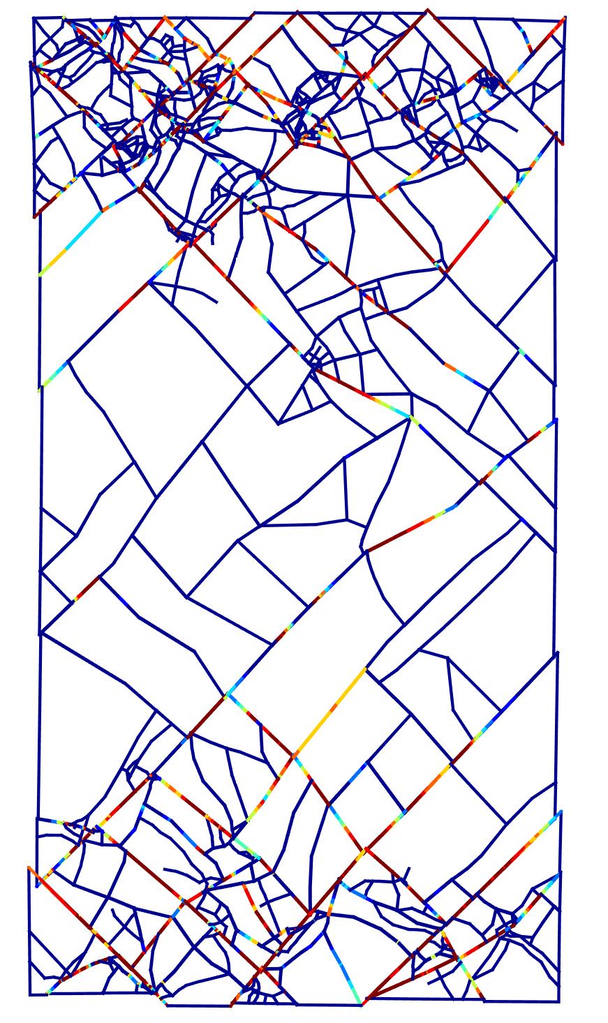

7 (a) `2, A0 = 1. (b) `2, A0 = 0.1. (c) `2, A0 = (d) `2, A0 = (e) MC, A0 = 1. (f) MC, A0 = 0.1. (g) MC, A0 = (h) MC, A0 = Figure 7: Comparison of space meshes and damage for the `2 and MC effective stress models with varying reference area, A0. Damage values on crack segments in the range, D [0, 1], are mapped to a blue-to-red color range. The solutions are shown for time t = 150 µs. (a) `2, A0 = 1. (b) `2, A0 = 0.1. (c) `2, A0 = (d) `2, A0 = (e) MC, A0 = 1. (f) MC, A0 = 0.1. (g) MC, A0 = (h) MC, A0 = Figure 8: Comparison of absolute slip fractions, asl, for the `2 and MC effective stress models with varying reference area, A0. Slip fractions on crack segments in the range, asl [0, 1], are mapped to a blue-to-red color range. The solutions are shown for time t = 150 µs. 7

 and (21a).")

8 (a) Solution. (b) Space mesh. (c) D. (d) η. (e) γ. (f) asl. (g) Solution. (h) Space mesh. (i) D. (j) η. (k) γ. (l) asl. (m) Solution. (n) Space mesh. (o) D. (p) η. (q) γ. (r) asl. Figure 9: Solution for Mohr Coulomb effective stress model and reference area, A0 = 0.1. Top, middle, and bottom rows correspond, respectively, to t = 48µs, 108µs, and 150µs. Color in the solution visualizations in the first column depicts strain energy density; low high values map to blue red MPa, respectively, for A = W H = m2 in (22). The compressive strengths for k = 0.3 are p `2 = 0.6 s and p MC = s; cf. (20a) and (21a). The purpose of this example is to compare the responses of the `2 and MC effective stress models and to study the influence of stochastic distributions of fracture strength, s. Specifically, we specify parameters m = 4, η = 4 MPa, and smin = 1.1MPa in the Weibull model. We investigate four values of A0, chosen to represent a range of weak to strong fracture strengths, as discussed below. Before the compressive waves from the two sides intersect in the center horizontal line, the compress stress experienced is σ0 = 2.5MPa. A crack is nucleated if σ0 p with p being a stochastic value, given that s is sampled based on the Weibull model. From the values reported above, it is evident that for the two models and A0 = 1 m2, 0.1 m2 the mean compressive strength is considerably greater than compressive stress σ0 ; thus fewer nucleated points are expected. The sampled compressive strengths decrease and more cracks are expected to nucleate as A0 0. This trend is evident in the results obtained with both models, although more cracks are generated with the `2 model given its slightly lower compressive strengths. Figure 7 compares crack patterns and adapted meshes using the `2 (top row) and Mohr Coulomb (bottom row) effective stress models for four reference area values, A0 = 1m2, 0.1m2, 0.01m2, and 0.001m2. The solutions are shown at time t = 150 µs, which is substantially past the time compressive waves from the top boundary impinge on those propagating from the bottom boundary at t = 14.3 µs. That is, the compressive stresses propagated from the two boundaries have already integrated and generate compressive stresses larger than those generated by each individual wave. These generate mean fracture strengths, E( s) = MPa, 7.16 MPa, 4.50 MPa, and The two models generate distinct fracture angles, as expected. The numerical results for the `2 model in figs. 7(a-d) agree with the prediction, θ`2 = 45, from (20b). 8

9 The crack angles for the Mohr Coulomb model in figs. 7(eh) cluster around θ MC = (measured with respect to the vertical direction), as predicted by (21b). From a computational perspective, it is clear that the h-adaptive asdg method is fully capable of capturing complex fracture patterns, particularly for smaller values of A 0, and exactly aligning element boundaries with crack propagation directions. Modifying A 0 to vary the stochastic fracture strength impacts the fracture response in several ways. In fig. 7, we observe more crack nucleations as A 0 decreases, but also, more crack segments with incomplete damage. The increase in nucleations is expected because reducing A 0 reduces the mean nucleation strength. However, a larger fraction of the nucleated cracks fail to reach full damage because higher crack densities produce more dynamic shielding between cracks, and overall, relax the initial dynamic loading. This leads to slower damage rates and more cases of incomplete fracture than in specimens with higher nucleation resistance and fewer cracks. Figure 8 depicts the absolute slip area fraction a SL (10b) on crack surfaces in the deformed geometry. This figure confirms that as more cracks nucleate, a smaller fraction of the total fracture surface fully debonds to allow active sliding (a SL = 1). For larger values of A 0, we observe longer fracture segments and longer segments involved in active sliding. Figure 9 depicts various aspects of the evolution of the numerical solution of the Mohr Coulomb model with A 0 = 0.1 to shed more light on the formation and activation of slip lines. on the wellbore walls, ramping from ambient pressure to 27.5 MPa in 750 ns. Unlike typical hydraulic fracturing practice, there are no pre-cut perforations to initiate fracture in this example. Instead, we rely on the stochastic model of in-situ defects to nucleate fracture. Figure 11 shows a solution sequence obtained with the Mohr Coulomb effective stress model. Physically, the high pressures of the detonation cause the rock to fail and compact. After the stress wave passes, the rock unloads elastically, leaving an enlarged, deformed wellbore, a zone of compacted rock and a region of greater compressive stress. The cracks are almost all in shear/compressive mode. Figures 12, 13, 14, and 15 compare solutions, crack patterns, space meshes, and various fields on the crack surfaces from the two effective stress models. The results confirm the enlarged deformed shape and almost instantaneous and uniform damage state around the wellbore. Moreover, figs. 12, 14, and 15 confirm full damage, contact mode, and slip of crack surfaces in this zone. We also observe that the fracture surfaces have propagated well beyond the region of full damage, however, given the finite time needed for damage evolution, cf. (11), and attenuation of the compressive wave, they accumulate very little damage. In comparison to the l 2 model, the Mohr Coulomb model generates slightly steeper crack angles relative to the wellbore surface and has more spread, although its damage zone is less concentrated. 6 CONCLUSIONS Figure 10: example. Problem sketch for explosive fracturing 5.3 Explosive fracturing Consider a pressurized wellbore subjected to far-field confining stresses, as shown in Figure 10. The wellbore has a diameter of 30 cm and is subjected to hydrostatic in-situ confining stresses, given by σ h = MPa. The bulk material properties are: Young s modulus E = 20GPa, mass density ρ = 2500 kg/m 3, and Poisson s ratio v = 0.2. The Weibull parameters are m = 4, η = 4MPa, s min = 500kPa, and A 0 = 0.1 m 2. An explosive compressive load acts We proposed two effective stress models for crack nucleation and the evolution of interfacial damage on fracture surfaces. We related the models to Tresca and Mohr- Coulomb failure criteria for rock under compressive loading. Our numerical results for a dynamic rock compaction problem demonstrate that the majority of cracks form along directions predicted by the two models. We used a stochastic strength model to nucleate new fractures cracks. Numerical experiments showed that stochastic representations of weaker materials result in more crack nucleation but a smaller fraction reaching full damage and slip conditions. While our results demonstrate the ability of the damage model and the h-adaptive asdg method to model and capture complex fracture response, we do not expect the proposed effective stress models to correctly model fracture in rock under more general loading conditions. The l 2 model does not capture the strengthening of rock under increasing confining pressure, and the linearity of the Mohr Coulomb model over-estimates tensile strength. This results in nonphysical fracture patterns for predominantly tensile crack propagation. We plan to investigate more advanced failure criteria, e.g., [8, 24, 25], to formulate more robust effective stress models for dynamic fracture in rock. 9
 Time t = 30 µs. (e) Time t = 45 µs.")


 l 2 effective stress model.")


![range, D [0, 1], are mapped to a blue-to-red color range. 10](/docs-images/94/119508622/images/10-6.jpg)
10 (a) Time t = 7.5 µs. (b) Time t = 15 µs. (c) Time t = 25 µs. (d) Time t = 30 µs. (e) Time t = 45 µs. (f) Time t = 57.5 µs. Figure 11: Solution visualization of well fracture with Mohr Coulomb effective stress model. Strain energy density is mapped to color with blue-to-red range indicating low to high values. (a) l 2 effective stress model. (b) Mohr Coulomb effective stress model. Figure 12: Comparison of solutions for l 2 and MC effective stress models at time t = 37.5 µs. Strain energy density is mapped to color with blue-to-red range indicating low to high values. (a) l 2 effective stress model. (b) Mohr Coulomb effective stress model. Figure 13: Comparison of space meshes and damage values for l 2 and MC effective stress models at time t = 37.5 µs. Damage values on crack segments in the range, D [0, 1], are mapped to a blue-to-red color range. 10

11 (a) l 2 effective stress model. (b) Mohr Coulomb effective stress model. Figure 14: Comparison of crack patterns and contact relative fractions, η, for l 2 and MC effective stress models at time t = 37.5 µs. Contact fractions on crack segments in the range, η [0, 1], are mapped to a blue-to-red color range. (a) l 2 effective stress model. (b) Mohr Coulomb effective stress model. Figure 15: Comparison of crack patterns and contact slip absolute fractions, a SL, for l 2 and MC effective stress models at time t = 37.5 µs. Contact slip fractions on crack segments in the range, a SL [0, 1], are mapped to a blue-to-red color range. REFERENCES [1] Paterson, Mervyn S and Teng-fong Wong (2005) Experimental rock deformation-the brittle field. Springer Science & Business Media. [2] Jaeger, JC and NGW Cook (1979) Fundamentals of rock mechanics. Chapman and Hall, New York. [3] Goodman, Richard E (1989) Introduction to rock mechanics, vol. 2. Wiley New York. [4] Barton, N. and V. Choubey (1977) The shear strength of rock joints in theory and practice. Rock mechanics, 10, [5] Wiebols, GA and NGW Cook (1968) An energy criterion for the strength of rock in polyaxial compression. International Journal of Rock Mechanics and Mining Sciences & Geomechanics Abstracts, vol. 5, pp , Elsevier. [6] Zhou, S (1994) A program to model the initial shape and extent of borehole breakout. Computers & Geosciences, 20, [7] Ewy, RT et al. (1999) Wellbore-stability predictions by use of a modified lade criterion. SPE Drilling & Completion, 14, [8] Singh, Mahendra, Anil Raj, and Bhawani Singh (2011) Modified mohr coulomb criterion for nonlinear triaxial and polyaxial strength of intact rocks. International Journal of Rock Mechanics and Mining Sciences, 48, [9] Abedi, Reza, Robert B. Haber, and Boris Petracovici (2006) A spacetime discontinuous Galerkin method for elastodynamics with element-level balance of linear momentum. Computer Methods in Applied Mechanics and Engineering, 195, [10] Abedi, R., R. B. Haber, S. Thite, and J. Erickson (2006) An h adaptive spacetime discontinuous Galerkin method for linearized elastodynamics. Revue Européenne de Mécanique Numérique (European Journal of Computational Mechanics), 15, [11] Abedi, Reza (2010) Spacetime damage-based cohesive model for elastodynamic fracture with dynamic contact. Ph.D. thesis, Department of Theoretical and 11
12 Applied Mechanics, University of Illinois at Urbana Champaign. [12] Omidi, Omid, Reza Abedi, and Saeid Enayatpour (2016) Well stimulation in tight formations: a dynamic approach. Proceeding: 50th US Rock Mechanics/Geomechanics Symposium, June 26-June 29, Houston, Texas - USA, pp. ARMA (12 pages). [13] Abedi, R., O. Omidi, and P.L. Clarke (2016) Numerical simulation of rock dynamic fracturing and failure including microscale material randomness. Proceeding: 50th US Rock Mechanics/Geomechanics Symposium, June 26-June 29, Houston, Texas - USA, pp. ARMA (13 pages). [14] Abedi, Reza and Robert B. Haber (2014) Riemann solutions and spacetime discontinuous Galerkin method for linear elastodynamic contact. Computer Methods in Applied Mechanics and Engineering, 270, [15] Bazant, Zdenek P., Ted B. Belytschko, and Ta-Peng Chang (1984) Continuum theory for strain-softening. Journal of Engineering Mechanics, 110, [16] Allix, O., P. Feissel, and P. Thevenet (2003) A delay damage mesomodel of laminates under dynamic loading: basic aspects and identification issues. Computers and Structures, 81, [17] Needleman, A. (1988) Material rate dependence and mesh sensitivity in localization problems. Computer Methods in Applied Mechanics and Engineering, 67, [18] Corigliano, A and M Ricci (2001) Rate-dependent interface models: formulation and numerical applications. International Journal of Solids and Structures, 38, [19] Allix, O. and A. Corigliano (1996) Modeling and simulation of crack propagation in mixed modes interlaminar fracture. International Journal of Fracture, 77, [20] Camacho, G. T. and M. Ortiz (1996) Computational modelling of impact damage in brittle materials. International Journal of Solids and Structures, 33, [21] Weibull, W. (1939) A statistical theory of the strength of materials. R. Swed. Inst. Eng. Res., p. Res [22] Weibull, W. (1951) A statistical distribution function of wide applicability. Journal of Applied Mechanics, 18, [23] Omidi, Omid, Reza Abedi, and Saeid Enayatpour (2015) An adaptive meshing approach to capture hydraulic fracturing. The 49th US Rock Mechanics/Geomechanics Symposium, June 28-July 1, San Francisco,CA,USA. [24] Hoek, E. and T. Brown (1980) Underground Excavations in Rock. Geotechnics and foundations, Taylor & Francis. [25] Hoek, E, CT Carranza-Torres, and B Corkum (2002) Hoek-brown failure criterion 2002 edition. In Proceedings of Proceedings of the fifth North American rock mechanics symposium, Toronto, Canada, vol. 1, pp
A computational approach to model dynamic contact and fracture mode transitions in rock, Part I: Formulation and compressive fracture
 A computational approach to model dynamic contact and fracture mode transitions in rock, Part I: Formulation and compressive fracture Reza Abedi a,1, Philip L. Clarke b a Associate professor, Department
Modeling of rock inhomogeneity and anisotropy by explicit and implicit representation of microcracks
 ARMA 18-1094 Modeling of rock inhomogeneity and anisotropy by explicit and implicit representation of microcracks Abedi, R., Clarke, P.L. Department of Mechanical, Aerospace & Biomedical Engineering, The
Module 5: Failure Criteria of Rock and Rock masses. Contents Hydrostatic compression Deviatoric compression
 FAILURE CRITERIA OF ROCK AND ROCK MASSES Contents 5.1 Failure in rocks 5.1.1 Hydrostatic compression 5.1.2 Deviatoric compression 5.1.3 Effect of confining pressure 5.2 Failure modes in rocks 5.3 Complete
Simulation of the cutting action of a single PDC cutter using DEM
 Petroleum and Mineral Resources 143 Simulation of the cutting action of a single PDC cutter using DEM B. Joodi, M. Sarmadivaleh, V. Rasouli & A. Nabipour Department of Petroleum Engineering, Curtin University,
Rock Failure. Topics. Compressive Strength Rock Strength from Logs Polyaxial Strength Criteria Anisotropic Rock Strength Tensile Strength
 Rock Failure Topics Compressive Strength Rock Strength from Logs Polyaxial Strength Criteria Anisotropic Rock Strength Tensile Strength Key Points 1. When rock fails in compression, the compressive stress
DEM simulation of fracture process of inherently anisotropic rock under Brazilian test condition
 Title DEM simulation of fracture process of inherently anisotropic rock under Brazilian test condition Author(s) Kwok, CY; Duan, K Citation The 49th US Rock Mechanics / Geomechanics Symposium, San Francisco,
Effect of intermediate principal stresses on compressive strength of Phra Wihan sandstone
 Rock Mechanics, Fuenkajorn & Phien-wej (eds) 211. ISBN 978 974 533 636 Effect of intermediate principal stresses on compressive strength of Phra Wihan sandstone T. Pobwandee & K. Fuenkajorn Geomechanics
Brittle Deformation. Earth Structure (2 nd Edition), 2004 W.W. Norton & Co, New York Slide show by Ben van der Pluijm
, 2004 W.W. Norton & Co, New York Slide show by Ben van der Pluijm") Lecture 6 Brittle Deformation Earth Structure (2 nd Edition), 2004 W.W. Norton & Co, New York Slide show by Ben van der Pluijm WW Norton, unless noted otherwise Brittle deformation EarthStructure (2 nd
Lecture 6 Brittle Deformation Earth Structure (2 nd Edition), 2004 W.W. Norton & Co, New York Slide show by Ben van der Pluijm WW Norton, unless noted otherwise Brittle deformation EarthStructure (2 nd
Classical fracture and failure hypotheses
 : Chapter 2 Classical fracture and failure hypotheses In this chapter, a brief outline on classical fracture and failure hypotheses for materials under static loading will be given. The word classical
MEMORANDUM SUBJECT: CERTIFICATE IN ROCK MECHANICS PAPER 1 : THEORY SUBJECT CODE: COMRMC MODERATOR: H YILMAZ EXAMINATION DATE: OCTOBER 2017 TIME:
 MEMORANDUM SUBJECT: CERTIFICATE IN ROCK MECHANICS PAPER 1 : THEORY EXAMINER: WM BESTER SUBJECT CODE: COMRMC EXAMINATION DATE: OCTOBER 2017 TIME: MODERATOR: H YILMAZ TOTAL MARKS: [100] PASS MARK: (60%)
Introduction and Background
 Introduction and Background Itasca Consulting Group, Inc. (Itasca) has been participating in the geomechanical design of the underground 118-Zone at the Capstone Minto Mine (Minto) in the Yukon, in northwestern
Understanding hydraulic fracture variability through a penny shaped crack model for pre-rupture faults
 Penny shaped crack model for pre-rupture faults Understanding hydraulic fracture variability through a penny shaped crack model for pre-rupture faults David Cho, Gary F. Margrave, Shawn Maxwell and Mark
Experimental study of mechanical and thermal damage in crystalline hard rock
 Experimental study of mechanical and thermal damage in crystalline hard rock Mohammad Keshavarz Réunion Technique du CFMR - Thèses en Mécanique des Roches December, 3 nd 2009 1 Overview Introduction Characterization
Geology 229 Engineering Geology. Lecture 5. Engineering Properties of Rocks (West, Ch. 6)
") Geology 229 Engineering Geology Lecture 5 Engineering Properties of Rocks (West, Ch. 6) Common mechanic properties: Density; Elastic properties: - elastic modulii Outline of this Lecture 1. Uniaxial rock
Geology 229 Engineering Geology Lecture 5 Engineering Properties of Rocks (West, Ch. 6) Common mechanic properties: Density; Elastic properties: - elastic modulii Outline of this Lecture 1. Uniaxial rock
Mechanics of Earthquakes and Faulting
 Mechanics of Earthquakes and Faulting www.geosc.psu.edu/courses/geosc508 Surface and body forces Tensors, Mohr circles. Theoretical strength of materials Defects Stress concentrations Griffith failure
The Frictional Regime
 The Frictional Regime Processes in Structural Geology & Tectonics Ben van der Pluijm WW Norton+Authors, unless noted otherwise 1/25/2016 10:08 AM We Discuss The Frictional Regime Processes of Brittle Deformation
Failure and Failure Theories for Anisotropic Rocks
 17th international Mining Congress and Exhibition of Turkey- IMCET 2001, 2001, ISBN 975-395-417-4 Failure and Failure Theories for Anisotropic Rocks E. Yaşar Department of Mining Engineering, Çukurova
A circular tunnel in a Mohr-Coulomb medium with an overlying fault
 MAP3D VERIFICATION EXAMPLE 9 A circular tunnel in a Mohr-Coulomb medium with an overlying fault 1 Description This example involves calculating the stresses and displacements on a fault overlying a 5 m
Strength, creep and frictional properties of gas shale reservoir rocks
 ARMA 1-463 Strength, creep and frictional properties of gas shale reservoir rocks Sone, H. and Zoback, M. D. Stanford University, Stanford, CA, USA Copyright 21 ARMA, American Rock Mechanics Association
Ch 4a Stress, Strain and Shearing
 Ch. 4a - Stress, Strain, Shearing Page 1 Ch 4a Stress, Strain and Shearing Reading Assignment Ch. 4a Lecture Notes Sections 4.1-4.3 (Salgado) Other Materials Handout 4 Homework Assignment 3 Problems 4-13,
ROCK MASS PROPERTIES FOR TUNNELLING
 ROCK MASS PROPERTIES FOR TUNNELLING Robert Bertuzzi 2 nd November 2017 1 Driver Estimating the strength and deformation characteristics of a rock mass for tunnel design is generally based on empiricism
ON THE FACE STABILITY OF TUNNELS IN WEAK ROCKS
 33 rd 33 Annual rd Annual General General Conference conference of the Canadian of the Canadian Society for Society Civil Engineering for Civil Engineering 33 e Congrès général annuel de la Société canadienne
EDEM DISCRETIZATION (Phase II) Normal Direction Structure Idealization Tangential Direction Pore spring Contact spring SPRING TYPES Inner edge Inner d
 Normal Direction Structure Idealization Tangential Direction Pore spring Contact spring SPRING TYPES Inner edge Inner d") Institute of Industrial Science, University of Tokyo Bulletin of ERS, No. 48 (5) A TWO-PHASE SIMPLIFIED COLLAPSE ANALYSIS OF RC BUILDINGS PHASE : SPRING NETWORK PHASE Shanthanu RAJASEKHARAN, Muneyoshi
Institute of Industrial Science, University of Tokyo Bulletin of ERS, No. 48 (5) A TWO-PHASE SIMPLIFIED COLLAPSE ANALYSIS OF RC BUILDINGS PHASE : SPRING NETWORK PHASE Shanthanu RAJASEKHARAN, Muneyoshi
Application of a transversely isotropic brittle rock mass model in roof support design
 University of Wollongong Research Online Coal Operators' Conference Faculty of Engineering and Information Sciences 2012 Application of a transversely isotropic brittle rock mass model in roof support
Mechanics of Earthquakes and Faulting
 Mechanics of Earthquakes and Faulting Lectures & 3, 9/31 Aug 017 www.geosc.psu.edu/courses/geosc508 Discussion of Handin, JGR, 1969 and Chapter 1 Scholz, 00. Stress analysis and Mohr Circles Coulomb Failure
STRESS DROP AS A RESULT OF SPLITTING, BRITTLE AND TRANSITIONAL FAULTING OF ROCK SAMPLES IN UNIAXIAL AND TRIAXIAL COMPRESSION TESTS
 Studia Geotechnica et Mechanica, Vol. 37, No. 1, 2015 DOI: 10.1515/sgem-2015-0003 STRESS DROP AS A RESULT OF SPLITTING, BRITTLE AND TRANSITIONAL FAULTING OF ROCK SAMPLES IN UNIAXIAL AND TRIAXIAL COMPRESSION
Fluid driven cohesive crack propagation in quasi-brittle materials
 Fluid driven cohesive crack propagation in quasi-brittle materials F. Barpi 1, S. Valente 2 Department of Structural and Geotechnical Engineering, Politecnico di Torino, Corso Duca degli Abruzzi 24, 10129
Analysis of Blocky Rock Slopes with Finite Element Shear Strength Reduction Analysis
 Analysis of Blocky Rock Slopes with Finite Element Shear Strength Reduction Analysis R.E. Hammah, T. Yacoub, B. Corkum & F. Wibowo Rocscience Inc., Toronto, Canada J.H. Curran Department of Civil Engineering
Haulage Drift Stability Analysis- A Sensitivity Approach
 Haulage Drift Stability Analysis- A Sensitivity Approach W. Abdellah University of Assiut, Assiut, Egypt ABSTRACT Haulage drifts are the primary access to the mining blocks of an ore body in a multi-level
ANSYS Mechanical Basic Structural Nonlinearities
 Lecture 4 Rate Independent Plasticity ANSYS Mechanical Basic Structural Nonlinearities 1 Chapter Overview The following will be covered in this Chapter: A. Background Elasticity/Plasticity B. Yield Criteria
Rock slope failure along non persistent joints insights from fracture mechanics approach
 Rock slope failure along non persistent joints insights from fracture mechanics approach Louis N.Y. Wong PhD(MIT), BSc(HKU) Assistant Professor and Assistant Chair (Academic) Nanyang Technological University,
Lecture #7: Basic Notions of Fracture Mechanics Ductile Fracture
 Lecture #7: Basic Notions of Fracture Mechanics Ductile Fracture by Dirk Mohr ETH Zurich, Department of Mechanical and Process Engineering, Chair of Computational Modeling of Materials in Manufacturing
Lecture #8: Ductile Fracture (Theory & Experiments)
") Lecture #8: Ductile Fracture (Theory & Experiments) by Dirk Mohr ETH Zurich, Department of Mechanical and Process Engineering, Chair of Computational Modeling of Materials in Manufacturing 2015 1 1 1 Ductile
Lecture #8: Ductile Fracture (Theory & Experiments) by Dirk Mohr ETH Zurich, Department of Mechanical and Process Engineering, Chair of Computational Modeling of Materials in Manufacturing 2015 1 1 1 Ductile
Modelling dynamic fracture propagation in rock
 University of Wollongong Research Online Faculty of Engineering and Information Sciences - Papers: Part B Faculty of Engineering and Information Sciences 2017 Modelling dynamic fracture propagation in
Geomechanics, Anisotropy and LMR
 Geomechanics, Anisotropy and LMR Marco Perez *, Apache Canada Ltd, Calgary, AB, Canada marco.perez@apachecorp.com Bill Goodway, Apache Canada Ltd, Calgary, AB, Canada bill.goodway@apachecorp.com David
Wellbore stability analysis in porous carbonate rocks using cap models
 Wellbore stability analysis in porous carbonate rocks using cap models L. C. Coelho 1, A. C. Soares 2, N. F. F. Ebecken 1, J. L. D. Alves 1 & L. Landau 1 1 COPPE/Federal University of Rio de Janeiro, Brazil
Weak Rock - Controlling Ground Deformations
 EOSC 547: Tunnelling & Underground Design Topic 7: Ground Characteristic & Support Reaction Curves 1 of 35 Tunnelling Grad Class (2014) Dr. Erik Eberhardt Weak Rock - Controlling Ground Deformations To
Calculation of periodic roof weighting interval in longwall mining using finite element method
 Calculation of periodic roof weighting interval in longwall mining using finite element method Navid Hosseini 1, Kamran Goshtasbi 2, Behdeen Oraee-Mirzamani 3 Abstract The state of periodic loading and
Numerical modeling of standard rock mechanics laboratory tests using a finite/discrete element approach
 Numerical modeling of standard rock mechanics laboratory tests using a finite/discrete element approach S. Stefanizzi GEODATA SpA, Turin, Italy G. Barla Department of Structural and Geotechnical Engineering,
Rock Mechanics and Rock Engineering
 Rock Mechanics and Rock Engineering Overview Rock mechanics is the theoretical and applied science of the mechanical behaviour of rock and rock masses. Rock mechanics deals with the mechanical properties
COMPARISON OF COHESIVE ZONE MODELS USED TO PREDICT DELAMINATION INITIATED FROM FREE-EDGES : VALIDATION AGAINST EXPERIMENTAL RESULTS
 COMPARISON OF COHESIVE ZONE MODELS USED TO PREDICT DELAMINATION INITIATED FROM FREE-EDGES : VALIDATION AGAINST EXPERIMENTAL RESULTS A. Uguen 1, L. Zubillaga 2, A. Turon 3, N. Carrère 1 1 Laboratoire Brestois
SEMM Mechanics PhD Preliminary Exam Spring Consider a two-dimensional rigid motion, whose displacement field is given by
 SEMM Mechanics PhD Preliminary Exam Spring 2014 1. Consider a two-dimensional rigid motion, whose displacement field is given by u(x) = [cos(β)x 1 + sin(β)x 2 X 1 ]e 1 + [ sin(β)x 1 + cos(β)x 2 X 2 ]e
Discrete Element Modelling of a Reinforced Concrete Structure
 Discrete Element Modelling of a Reinforced Concrete Structure S. Hentz, L. Daudeville, F.-V. Donzé Laboratoire Sols, Solides, Structures, Domaine Universitaire, BP 38041 Grenoble Cedex 9 France sebastian.hentz@inpg.fr
Fatigue Damage Development in a Steel Based MMC
 Fatigue Damage Development in a Steel Based MMC V. Tvergaard 1,T.O/ rts Pedersen 1 Abstract: The development of fatigue damage in a toolsteel metal matrix discontinuously reinforced with TiC particulates
Cohesive Band Model: a triaxiality-dependent cohesive model inside an implicit non-local damage to crack transition framework
 University of Liège Aerospace & Mechanical Engineering MS3: Abstract 131573 - CFRAC2017 Cohesive Band Model: a triaxiality-dependent cohesive model inside an implicit non-local damage to crack transition
Analysis of Controlling Parameters for Shear behavior of Rock Joints with FLAC3D
 International Journal of Structural and Civil Engineering Research Vol. 5, No. 1, February 2016 Analysis of Controlling Parameters for Shear behavior of Rock Joints with FLAC3D Prasoon Tiwari and Hakan
Material is perfectly elastic until it undergoes brittle fracture when applied stress reaches σ f
 Material is perfectly elastic until it undergoes brittle fracture when applied stress reaches σ f Material undergoes plastic deformation when stress exceeds yield stress σ 0 Permanent strain results from
Stability Assessment of a Heavily Jointed Rock Slope using Limit Equilibrium and Finite Element Methods
 Indian Geotechnical Conference 2017 GeoNEst 14-16 December 2017, IIT Guwahati, India Stability Assessment of a Heavily Jointed Rock Slope using Limit Equilibrium and Finite Element Methods Aswathi CK Amalesh
Rock Material. Chapter 3 ROCK MATERIAL HOMOGENEITY AND INHOMOGENEITY CLASSIFICATION OF ROCK MATERIAL
 Chapter 3 Rock Material In all things of nature there is something of the marvelous. Aristotle ROCK MATERIAL The term rock material refers to the intact rock within the framework of discontinuities. In
PLANES OF WEAKNESS IN ROCKS, ROCK FRCTURES AND FRACTURED ROCK. Contents
 PLANES OF WEAKNESS IN ROCKS, ROCK FRCTURES AND FRACTURED ROCK Contents 7.1 Introduction 7.2 Studies On Jointed Rock Mass 7.2.1 Joint Intensity 7.2.2 Orientation Of Joints 7.2.3 Joint Roughness/Joint Strength
Mechanics of Earthquakes and Faulting
 Mechanics of Earthquakes and Faulting www.geosc.psu.edu/courses/geosc508 Overview Milestones in continuum mechanics Concepts of modulus and stiffness. Stress-strain relations Elasticity Surface and body
c 2014 Kartik Marwah
 c 2014 Kartik Marwah NUMERICAL SIMULATION OF FRAGMENTATION AND SPALLING AND PARALLELIZATION OF A SPACETIME FINITE ELEMENT CODE BY KARTIK MARWAH THESIS Submitted in partial fulfillment of the requirements
Dynamic Analysis of a Reinforced Concrete Structure Using Plasticity and Interface Damage Models
 Dynamic Analysis of a Reinforced Concrete Structure Using Plasticity and Interface Damage Models I. Rhee, K.J. Willam, B.P. Shing, University of Colorado at Boulder ABSTRACT: This paper examines the global
Numerical investigation of EDZ development around a deep polymetallic ore mine
 Paper No. 198 ISMS 2016 Numerical investigation of EDZ development around a deep polymetallic ore mine Mountaka Souley a *, Marwan Al Heib a, Vincent Renaud a a INERIS, c/o Ecole des Mines de Nancy, Campus
Methods of Interpreting Ground Stress Based on Underground Stress Measurements and Numerical Modelling
 University of Wollongong Research Online Coal Operators' Conference Faculty of Engineering and Information Sciences 2006 Methods of Interpreting Ground Stress Based on Underground Stress Measurements and
Comparison between a Cohesive Zone Model and a Continuum Damage Model in Predicting Mode-I Fracture Behavior of Adhesively Bonded Joints
 Copyright 2012 Tech Science Press CMES, vol.83, no.2, pp.169-181, 2012 Comparison between a Cohesive Zone Model and a Continuum Damage Model in Predicting Mode-I Fracture Behavior of Adhesively Bonded
Critical Borehole Orientations Rock Mechanics Aspects
 Critical Borehole Orientations Rock Mechanics Aspects By R. BRAUN* Abstract This article discusses rock mechanics aspects of the relationship between borehole stability and borehole orientation. Two kinds
6. NON-LINEAR PSEUDO-STATIC ANALYSIS OF ADOBE WALLS
 6. NON-LINEAR PSEUDO-STATIC ANALYSIS OF ADOBE WALLS Blondet et al. [25] carried out a cyclic test on an adobe wall to reproduce its seismic response and damage pattern under in-plane loads. The displacement
Ground Support in Mining and Underground Construction
 Ground Support in Mining and Underground Construction Proceedings of the Fifth International Symposium on Ground Support 28-30 September 2004, Perth, Western Australia Edited by Ernesto Villaescusa Yves
Prediction of torsion shear tests based on results from triaxial compression tests
 Prediction of torsion shear tests based on results from triaxial compression tests P.L. Smith 1 and N. Jones *2 1 Catholic University of America, Washington, USA 2 Geo, Lyngby, Denmark * Corresponding
Concrete Fracture Prediction Using Virtual Internal Bond Model with Modified Morse Functional Potential
 Concrete Fracture Prediction Using Virtual Internal Bond Model with Modified Morse Functional Potential Kyoungsoo Park, Glaucio H. Paulino and Jeffery R. Roesler Department of Civil and Environmental Engineering,
THE VOUSSOIR BEAM REACTION CURVE
 THE VOUSSOIR BEAM REACTION CURVE Yossef H. Hatzor Ben-Gurion University, Department of Geological and Environmental Sciences Beer-Sheva, Israel, 84105 ABSTRACT: The influence of joint spacing (s) on the
Discrete Element Modeling of Thermo-Hydro-Mechanical Coupling in Enhanced Geothermal Reservoirs
 PROCEEDINGS, Thirty-Eighth Workshop on Geothermal Reservoir Engineering Stanford University, Stanford, California Discrete Element Modeling of Thermo-Hydro-Mechanical Coupling in Enhanced Geothermal Reservoirs
Tectonics. Lecture 12 Earthquake Faulting GNH7/GG09/GEOL4002 EARTHQUAKE SEISMOLOGY AND EARTHQUAKE HAZARD
 Tectonics Lecture 12 Earthquake Faulting Plane strain 3 Strain occurs only in a plane. In the third direction strain is zero. 1 ε 2 = 0 3 2 Assumption of plane strain for faulting e.g., reverse fault:
Pressure Vessels Stresses Under Combined Loads Yield Criteria for Ductile Materials and Fracture Criteria for Brittle Materials
 Pressure Vessels Stresses Under Combined Loads Yield Criteria for Ductile Materials and Fracture Criteria for Brittle Materials Pressure Vessels: In the previous lectures we have discussed elements subjected
In situ fracturing mechanics stress measurements to improve underground quarry stability analyses
 In situ fracturing mechanics stress measurements to improve underground quarry stability analyses Anna M. Ferrero, Maria R. Migliazza, Andrea Segalini University of Parma, Italy Gian P. Giani University
ISMS Paper No Influence of weak planes on rockburst occurrence. Amin Manouchehrian, Ming Cai *
 Paper No. 176 ISMS 2016 Influence of weak planes on rockburst occurrence Amin Manouchehrian, Ming Cai * Bharti School of Engineering, Laurentian University, Sudbury, Canada, P3E 2C6 MIRARCO, Laurentian
An Energy Dissipative Constitutive Model for Multi-Surface Interfaces at Weld Defect Sites in Ultrasonic Consolidation
 An Energy Dissipative Constitutive Model for Multi-Surface Interfaces at Weld Defect Sites in Ultrasonic Consolidation Nachiket Patil, Deepankar Pal and Brent E. Stucker Industrial Engineering, University
Seismic analysis of horseshoe tunnels under dynamic loads due to earthquakes
 University of Wollongong Research Online Coal Operators' Conference Faculty of Engineering and Information Sciences 2010 Seismic analysis of horseshoe tunnels under dynamic loads due to earthquakes Navid
Dynamic Soil Pressures on Embedded Retaining Walls: Predictive Capacity Under Varying Loading Frequencies
 6 th International Conference on Earthquake Geotechnical Engineering 1-4 November 2015 Christchurch, New Zealand Dynamic Soil Pressures on Embedded Retaining Walls: Predictive Capacity Under Varying Loading
Mohr's Circle and Earth Stress (The Elastic Earth)
") Lect. 1 - Mohr s Circle and Earth Stress 6 Mohr's Circle and Earth Stress (The Elastic Earth) In the equations that we derived for Mohr s circle, we measured the angle, θ, as the angle between σ 1 and
Lect. 1 - Mohr s Circle and Earth Stress 6 Mohr's Circle and Earth Stress (The Elastic Earth) In the equations that we derived for Mohr s circle, we measured the angle, θ, as the angle between σ 1 and
Modeling of Interfacial Debonding Induced by IC Crack for Concrete Beam-bonded with CFRP
 Proceedings of the World Congress on Engineering 21 Vol II WCE 21, June 2 - July 1, 21, London, U.K. Modeling of Interfacial Debonding Induced by IC Crack for Concrete Beam-bonded with CFRP Lihua Huang,
Comparison of six major intact rock failure criteria using a particle flow approach under true-triaxial stress condition
 Geomech. Geophys. Geo-energ. Geo-resour. (1) :3 9 DOI.7/s9-1-3- ORIGINAL ARTICLE Comparison of six major intact rock failure criteria using a particle flow approach under true-triaxial stress condition
HYDRAULIC FRACTURE PROPAGATION NEAR A NATURAL DISCONTINUITY
 PROCEEDINGS, Twenty-Eight Workshop on Geothermal Reservoir Engineering Stanford University, Stanford, California, January 7-9, SGP-TR-7 HYDRAULIC FRACTURE PROPAGATION NEAR A NATURAL DISCONTINUITY V. Koshelev
Prof. B V S Viswanadham, Department of Civil Engineering, IIT Bombay
 51 Module 4: Lecture 2 on Stress-strain relationship and Shear strength of soils Contents Stress state, Mohr s circle analysis and Pole, Principal stressspace, Stress pathsin p-q space; Mohr-coulomb failure
strain appears only after the stress has reached a certain critical level, usually specied by a Rankine-type criterion in terms of the maximum princip
 Nonlocal damage models: Practical aspects and open issues Milan Jirasek LSC-DGC, Swiss Federal Institute of Technology at Lausanne (EPFL), Switzerland Milan.Jirasek@ep.ch Abstract: The purpose of this
Rock Joint and Rock Mass Shear Strength
 Rock Joint and Rock Mass Shear Strength GEO-SLOPE International Ltd. www.geo-slope.com 1400, 633-6th Ave SW, Calgary, AB, Canada T2P 2Y5 Main: +1 403 269 2002 Fax: +1 403 266 4851 Introduction SLOPE/W
I hereby declare that, except where specifically indicated, the work submitted herein is my own original work.
 Finite Element Studies on the Mechanical Stability of Arbitrarily Oriented and Inclined Wellbores Using a Vertical 3D Wellbore Model by Di Zien Low (F) Fourth-Year Undergraduate Project in Group D, 2010/2011
7 Uniaxial Compressive Strength of a Jointed Rock Sample
 Uniaxial Compressive Strength of a Jointed Rock Sample 7-1 7 Uniaxial Compressive Strength of a Jointed Rock Sample 7.1 Problem Statement The uniaxial compressive strength of a jointed rock sample is a
Module-4. Mechanical Properties of Metals
 Module-4 Mechanical Properties of Metals Contents ) Elastic deformation and Plastic deformation ) Interpretation of tensile stress-strain curves 3) Yielding under multi-axial stress, Yield criteria, Macroscopic
Flin Flon Mining Belt
 EOSC433: Geotechnical Engineering Practice & Design Lecture 7: Stress Analysis around Underground Openings 1 of 40 Erik Eberhardt UBC Geological Engineering EOSC 433 (2007) Flin Flon Mining Belt Since
3D Finite Element analysis of stud anchors with large head and embedment depth
 3D Finite Element analysis of stud anchors with large head and embedment depth G. Periškić, J. Ožbolt & R. Eligehausen Institute for Construction Materials, University of Stuttgart, Stuttgart, Germany
MAE 322 Machine Design. Dr. Hodge Jenkins Mercer University
 MAE 322 Machine Design Dr. Hodge Jenkins Mercer University What is this Machine Design course really about? What you will learn: How to design machine elements 1) Design so they won t break under varying
Chapter 7. Highlights:
 Chapter 7 Highlights: 1. Understand the basic concepts of engineering stress and strain, yield strength, tensile strength, Young's(elastic) modulus, ductility, toughness, resilience, true stress and true
DEVELOPMENT OF AUTOMATIC CONTROL OF MULTI-STAGE TRIAXIAL TESTS AT THE UNIVERSITY OF MISKOLC
 Geosciences and Engineering, Vol. 2, No. 3 (2013), pp. 37 43. DEVELOPMENT OF AUTOMATIC CONTROL OF MULTI-STAGE TRIAXIAL TESTS AT THE UNIVERSITY OF MISKOLC BALÁZS CSUHANICS ÁKOS DEBRECZENI Institute of Mining
Powerful Modelling Techniques in Abaqus to Simulate
 Powerful Modelling Techniques in Abaqus to Simulate Necking and Delamination of Laminated Composites D. F. Zhang, K.M. Mao, Md. S. Islam, E. Andreasson, Nasir Mehmood, S. Kao-Walter Email: sharon.kao-walter@bth.se
Numerical models on anisotropy of rocks
 NGM 206 Reykjavik Proceedings of the 7 th Nordic Geotechnical Meeting Challenges in Nordic Geotechnic 25 th 28 th of May Numerical models on anisotropy of rocks Henok M. Kassa Statoil ASA, Norway, hmka@statoil.com
VORONOI APPLIED ELEMENT METHOD FOR STRUCTURAL ANALYSIS: THEORY AND APPLICATION FOR LINEAR AND NON-LINEAR MATERIALS
 The 4 th World Conference on Earthquake Engineering October -7, 008, Beijing, China VORONOI APPLIED ELEMENT METHOD FOR STRUCTURAL ANALYSIS: THEORY AND APPLICATION FOR LINEAR AND NON-LINEAR MATERIALS K.
Numerical simulation of delamination onset and growth in laminated composites
 Numerical simulation of delamination onset and growth in laminated composites G. Wimmer, C. Schuecker, H.E. Pettermann Austrian Aeronautics Research (AAR) / Network for Materials and Engineering at the
Numerical Modeling of Direct Shear Tests on Sandy Clay
 Numerical Modeling of Direct Shear Tests on Sandy Clay R. Ziaie Moayed, S. Tamassoki, and E. Izadi Abstract Investigation of sandy clay behavior is important since urban development demands mean that sandy
Failure surface according to maximum principal stress theory
 Maximum Principal Stress Theory (W. Rankin s Theory- 1850) Brittle Material The maximum principal stress criterion: Rankin stated max principal stress theory as follows- a material fails by fracturing
NUMERICAL MODELING OF BRITTLE ROCK FAILURE UNDER DYNAMIC STRESS LOADING. N. Golchinfar and M. Cai
 NUMERICAL MODELING OF BRITTLE ROCK FAILURE UNDER DYNAMIC STRESS LOADING N. Golchinfar and M. Cai Laurentian University 935 Ramsey Lake Road Sudbury, Canada P3E 2C6 NUMERICAL MODELING OF BRITTLE ROCK FAILURE
MMJ1133 FATIGUE AND FRACTURE MECHANICS A - INTRODUCTION INTRODUCTION
 A - INTRODUCTION INTRODUCTION M.N.Tamin, CSMLab, UTM Course Content: A - INTRODUCTION Mechanical failure modes; Review of load and stress analysis equilibrium equations, complex stresses, stress transformation,
Analysis of stress variations with depth in the Permian Basin Spraberry/Dean/Wolfcamp Shale
 ARMA 15-189 Analysis of stress variations with depth in the Permian Basin Spraberry/Dean/Wolfcamp Shale Xu, Shaochuan and Zoback, M.D. Stanford University, Stanford, California, USA Copyright 2015 ARMA,
An Experimental Characterization of the Non-linear Rheology of Rock
 An Experimental Characterization of the Non-linear Rheology of Rock G. N. BorrNoTr New England Research Inc. Contract: F49620-95-C-0019 Sponsor: AFOSR ABSTRACT A laboratory experimental program is underway
Modelling the nonlinear shear stress-strain response of glass fibrereinforced composites. Part II: Model development and finite element simulations
 Modelling the nonlinear shear stress-strain response of glass fibrereinforced composites. Part II: Model development and finite element simulations W. Van Paepegem *, I. De Baere and J. Degrieck Ghent
Module 6: Stresses around underground openings. 6.2 STRESSES AROUND UNDERGROUND OPENING contd.
 LECTURE 0 6. STRESSES AROUND UNDERGROUND OPENING contd. CASE : When σ x = 0 For σ x = 0, the maximum tangential stress is three times the applied stress and occurs at the boundary on the X-axis that is
Cohesive Zone Modeling of Dynamic Fracture: Adaptive Mesh Refinement and Coarsening
 Cohesive Zone Modeling of Dynamic Fracture: Adaptive Mesh Refinement and Coarsening Glaucio H. Paulino 1, Kyoungsoo Park 2, Waldemar Celes 3, Rodrigo Espinha 3 1 Department of Civil and Environmental Engineering
Effect of embedment depth and stress anisotropy on expansion and contraction of cylindrical cavities
 Effect of embedment depth and stress anisotropy on expansion and contraction of cylindrical cavities Hany El Naggar, Ph.D., P. Eng. and M. Hesham El Naggar, Ph.D., P. Eng. Department of Civil Engineering
Numerical Analysis on the Interaction between Two Zipper Frac Wells with Continuum Damage Model
 Copyright 2013 Tech Science Press SL, vol.9, no.1, pp.1-22, 2013 Numerical Analysis on the Interaction between Two Zipper Frac Wells with Continuum Damage Model Xinpu Shen 1 Abstract: Zipper fracturing