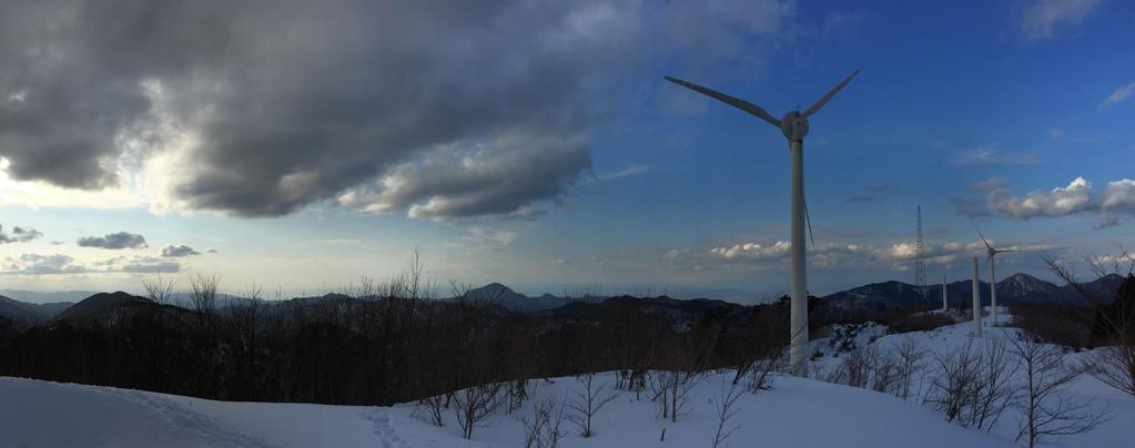
Power output: 6 750kW=4500kW Location: Top of Taikoyama, Kyoto prefecture, Japan. Terrain condition: Complex mountainous area
|
|
|
- Peregrine Young
- 5 years ago
- Views:
Transcription


1


2 Introduction Power output: 6 75kW=45kW Location: Top of Taikoyama, Kyoto prefecture, Japan m 45.94m Fracture section Terrain condition: Complex mountainous area m History: Nov, 21: Power generation began; Mar, 213: Nacelle of No.3 turbine collapsed Complex mountainous terrain results in high turbulence intensity 2/ Different from the situation in Europe 13
3 Questions 1. Wind turbine design life is 2 years; However this turbine nacelle collapsed only 12 years after construction. How could it collapsed at a middle age of its life time? 2. The No.3 turbine s high-tension bolts broke three times in 28, 212 and 213. After the last bolts replacement in 212, the nacelle collapsed within one year, although there was no damage detected according to the periodical inspection; Why the bolts broke frequently? Questions must be answered 3/ 13
4 Flow chart Wind condition investigation High turbulence; Ambiguous explanation is dangerous: 1) Solving problem; 2) Dividing responsibility. Fracture section investigation Material strength no problem; Fatigue cracks propagated at the tower tube inner surface. Quantitative analysis required Aerodynamic modelling; Understanding the force; Fatigue life evaluation. Spatial effect & stress concentration Accurate FEM model; Clarify the relationship between nominal stress and bolt stress Root cause 4/ 13
5 Objectives 1. Aerodynamic model is necessary in order to understand the response at the fracture section; 2. Filed and observation should be conducted to understand the complicated nacelle structure; 3. FEM model should be built accurately in order to recreate the complex strain distribution at fracture section, and to evaluate the fatigue life of high-tension bolt; 4. Bolts broke frequently. Root cause must be clarified. 5/ 13

6 Turbulence Intensity Moment (knm) Field Moment Ave moment, std moment and max moment Occurrence frequency West wind predominates Turbulence intensity ε s M SN ε W θ M total M EW ε E Nacelle direction ε N Moment calculation schematic diagram α Std moment Ave moment Max moment Plot of moment WNW W WSW 3% N NNW NNE NW 2% NE SW SSW 1% % S SE SSE ENE E ESE Occurrence frequency I p = U max U mean 1 P, P = 1 2 ln T t Extrapolated value for high wind speed (>17m/s) Measurement NTM(9% quantile) Bin (9% quantile) I v 1.I u I w.7i u Slope with gradient over 2 degree Turbulence intensity (W) Numerical topographic map High turbulence 6/ 13
7 Moment (knm) Moment (knm) Moment (knm) Power output (kw) Rotor speed (rpm) Pitch angle (deg) Power output (kw) Rotor speed (rpm) Pitch angle (deg) Aerodynamic modelling & modification Modelling Tower part Engineering drawings Blade shape and aerodynamic coefficient NREL airfoil family Modification of real turbine Power output: 75kW 63kW; Rotor speed: 33rpm 26rpm; Pitch angle: different Modification of model No information from manufacturer Pitch angle error 5 degree; Reduce both torque and thrust simulation designed simulation modified simulation modified 1 simulation 5deg Power output Power output simulation 5deg Ave moment Rotor speed Aerodynamic model is built based on real situation simulation designed simulation modified Rotor speed simulation modified simulation 5deg simulation 5deg Std moment simulation modified simulation 5deg simulation designed simulation modified Pitch angle Pitch angle simulation 5deg Max moment 7/ 13


 CH19 strain distribution Yaw motor Ball bearing")
8 Strain (με) Strain distribution at top flange joint Strain distribution should be understand Spatial effect & stress concentration Strain gauges arrangement Around 45.94m, CH9~CH32 Strain distribution 45.94m CH19 Fracture section Bolt Flange 2mm 2mm 6mm 1mm CH19 Dissatisfy the plane section assumption Nacelle investigation Nacelle weight transmits in three paths 3 Yaw motors 16 Yaw brakes 129 Ball bearings + m Rotor direction FEM model is necessary to recreate the strain distribution at fracture section CH19 CH1 Nacelle rotating plane graph Strain gauges layout at stage # Plain section assumption Measurement Nacelle ratational degree (deg) CH19 strain distribution Yaw motor Ball bearing Strain gauges installment Yaw brake Local view of yaw bearing 8/ 13


9 Strain (με) FEM modelling FEM model Solid element Ball bearing, pinion gear; Shell element Nacelle Spring element Yaw brake, ball bearing Beam element Bolts Strain distribution Good agreement Mechanism Yaw deformation is elliptical; Tower strain direction aft side is large; Tower strain in fore direction is small; Nacelle side view Concentrated mass Thrust force Pinion gear Yaw brake Ball bearing Upward view FEM Measurement fore aft Nacelle ratational degree (deg) Tower strain distribution 45.94m Fore Aft Yaw bearing deformation FEM model shows good agreement and necessary 9/ 13
10 Stress range (MPa) High tension bolt fatigue life (y) Nominal stress (N/mm 2 ) Bolt (N/mm2) Blot pre-tension stress (N/mm 2 ) Bolt fatigue life evaluation Relationship between nominal and bolt stress Nominal stress (45.94m): σ n =N/A-M/Z Nominal stress increases, gradient increases as pre-tension decreases Steeper gradient when pre-tension decreases Fatigue life Rainflow counting, S-N curve, miner s rule Max -1 Average Min Nominal stress (45.94m) % 8% 6% 4% 2% % Nominal stress (N/mm2) Nominal stress vs bolt pre-stress Pre-tension 2% Pre-tension % Time (s) Bolt pre-tension stress (14m/s) Life time drops drastically when pre-tension decreases Pre-tension is 8%: fatigue life 28 years ---- safe Pre-tension less than 8%: fatigue life < 2 years ---- failure Pre-tension less than 4%: fatigue life only a few days E+6 5.E E+5 1.E+6 1.E+7 1.E+8 1.E+9 Cycles Ni S-N curve DC % % %.97 4% 2%.17 Pre-tension force Bolts fatigue life vs. pre-tension (IEC A).4 % High turbulence is not the reason but reduction of bolts pre-tension 1/ 13
 Re-torqueing is important Reference force 265kN 8% Well")
 Bolt No.")
11 Pre-force (kn) Reason of bolt pre-tension reduction Pre-tension force is applied by torqueing F1T-M24 Torque: 85Nm Axial force: 265kN Indoor experiment Different wrenches and wrench If well lubricated: Pre-tension can be guaranteed with 1% variability Filed experiment Same with indoor Bolt force reduction ratio R = 1 L 15 (%) Re-torqueing is important Reference force 265kN 8% Well lubricated F1T-M24 1% variability Data logger Face ring lubricant Adhesive Strain gauge Female screw lubricant L Torque Power wrench Normal wrench Hydraulic wrench Bolt reduction ratio R (5 h after operation) Bolt No. L [mm] R [%] Torque (kn m) Indoor experiment Re-torqueing was not applied 5 hours after bolt replacement caused the reduction Bolt 11/ 13
12 Conclusions 1. Due to high turbulence, control method was adjust by manufacturer. Modification was applied to aerodynamic model ; 2. The strain distribution at fracture section is not abiding by plain section assumption due to complex nacelle structure and yaw motors constraint. FEM model was built accurately and shows good agreement with result; 3. The root cause of this accident is not the matter of high turbulence or design, but the reduction of bolts pre-tension. When pre-tension force is less than 8% the fatigue life decreases; 4. Re-torqueing is important to prevent pre-tension reduction. Communication between manufacturer and operation workers should be more effective. 12/ 13
13 This project is funded by the Kyoto Prefecture Government, New Energy and Industrial Technology Development Organization. I wish to express my deepest gratitude to the concerned parties for their assistance and contribution to this project
Fatigue Failure Accident of Wind Turbine Tower in Taikoyama Wind Farm
 Fatigue Failure Accident of Wind Turbine Tower in Taikoyama Wind Farm Yin LIU 1, Takeshi ISHIHARA 2 1,2 Department of Civil Engineering, School of Engineering, the University of Tokyo, Tokyo, Japan Abstract
Reduction of computational cost for design of wind turbine tower against fatigue failure
 No. E-13-AAA- Reduction of computational cost for design of wind turbine tower against fatigue failure Ali R. Fathi, Hamid R. Lari, Abbas Elahi Wind turbine Technology Development Center Niroo Research
Engineering Tripos Part IB. Part IB Paper 8: - ELECTIVE (2)
") Engineering Tripos Part IB SECOND YEAR Part IB Paper 8: - ELECTIVE (2) MECHANICAL ENGINEERING FOR RENEWABLE ENERGY SYSTEMS Examples Paper 2 Wind Turbines, Materials, and Dynamics All questions are of Tripos
Engineering Tripos Part IB SECOND YEAR Part IB Paper 8: - ELECTIVE (2) MECHANICAL ENGINEERING FOR RENEWABLE ENERGY SYSTEMS Examples Paper 2 Wind Turbines, Materials, and Dynamics All questions are of Tripos
Stress Analysis Lecture 3 ME 276 Spring Dr./ Ahmed Mohamed Nagib Elmekawy
 Stress Analysis Lecture 3 ME 276 Spring 2017-2018 Dr./ Ahmed Mohamed Nagib Elmekawy Axial Stress 2 Beam under the action of two tensile forces 3 Beam under the action of two tensile forces 4 Shear Stress
Adaptive Control of Variable-Speed Variable-Pitch Wind Turbines Using RBF Neural Network
 Schulich School of Engineering Department of Mechanical and Manufacturing Engineering Adaptive Control of Variable-Speed Variable-Pitch Wind Turbines Using RBF Neural Network By: Hamidreza Jafarnejadsani,
SOLUTION (17.3) Known: A simply supported steel shaft is connected to an electric motor with a flexible coupling.
 Known: A simply supported steel shaft is connected to an electric motor with a flexible coupling.") SOLUTION (17.3) Known: A simply supported steel shaft is connected to an electric motor with a flexible coupling. Find: Determine the value of the critical speed of rotation for the shaft. Schematic and
SOLUTION (17.3) Known: A simply supported steel shaft is connected to an electric motor with a flexible coupling. Find: Determine the value of the critical speed of rotation for the shaft. Schematic and
Dimensions of propulsion shafts and their permissible torsional vibration stresses
 (Feb 2005) (orr.1 Mar 2012) (orr.2 Nov 2012) Dimensions of propulsion shafts and their permissible torsional vibration stresses.1 Scope This UR applies to propulsion shafts such as intermediate and propeller
Special edition paper
 Development of New Aseismatic Structure Using Escalators Kazunori Sasaki* Atsushi Hayashi* Hajime Yoshida** Toru Masuda* Aseismatic reinforcement work is often carried out in parallel with improvement
3 Hours/100 Marks Seat No.
 *17304* 17304 14115 3 Hours/100 Marks Seat No. Instructions : (1) All questions are compulsory. (2) Illustrate your answers with neat sketches wherever necessary. (3) Figures to the right indicate full
my!wind Ltd 5 kw wind turbine Static Stability Specification
 my!wind Ltd 5 kw wind turbine Static Stability Specification 1 P a g e 0 3 / 0 4 / 2 0 1 4 Contents Contents... 2 List of Changes... 2 Appendixes... 2 General remarks... 3 1. Introduction... 4 2. Geometry...
QUESTION BANK SEMESTER: III SUBJECT NAME: MECHANICS OF SOLIDS
 QUESTION BANK SEMESTER: III SUBJECT NAME: MECHANICS OF SOLIDS UNIT 1- STRESS AND STRAIN PART A (2 Marks) 1. Define longitudinal strain and lateral strain. 2. State Hooke s law. 3. Define modular ratio,
Fatigue Reliability and Effective Turbulence Models in Wind Farms
 Downloaded from vbn.aau.dk on: marts 28, 2019 Aalborg Universitet Fatigue Reliability and Effective Turbulence Models in Wind Farms Sørensen, John Dalsgaard; Frandsen, S.; Tarp-Johansen, N.J. Published
Matlab Sheet 2. Arrays
 Matlab Sheet 2 Arrays 1. a. Create the vector x having 50 logarithmically spaced values starting at 10 and ending at 1000. b. Create the vector x having 20 logarithmically spaced values starting at 10
This guide is made for non-experienced FEA users. It provides basic knowledge needed to start your fatigue calculations quickly.
 Quick Fatigue Analysis Guide This guide is made for non-experienced FEA users. It provides basic knowledge needed to start your fatigue calculations quickly. Experienced FEA analysts can also use this
Uncertainty in wind climate parameters and the consequence for fatigue load assessment
 Uncertainty in wind climate parameters and the consequence for fatigue load assessment Henrik Stensgaard Toft (1,2) Lasse Svenningsen (2), Morten Lybech Thøgersen (2), John Dalsgaard Sørensen (1) (1) Aalborg
Effect of linear and non-linear blade modelling techniques on simulated fatigue and extreme loads using Bladed
 Journal of Physics: Conference Series PAPER OPEN ACCESS Effect of linear and non-linear blade modelling techniques on simulated fatigue and extreme loads using Bladed To cite this article: Alec Beardsell
EMA 3702 Mechanics & Materials Science (Mechanics of Materials) Chapter 3 Torsion
 Chapter 3 Torsion") EMA 3702 Mechanics & Materials Science (Mechanics of Materials) Chapter 3 Torsion Introduction Stress and strain in components subjected to torque T Circular Cross-section shape Material Shaft design Non-circular
EMA 3702 Mechanics & Materials Science (Mechanics of Materials) Chapter 3 Torsion Introduction Stress and strain in components subjected to torque T Circular Cross-section shape Material Shaft design Non-circular
H ROBUST CONTROLLER FOR WIND TURBINE POWER BOOSTING
 27 ROBUST CONTROLLER FOR WIND TURBINE POWER BOOSTING H ROBUST CONTROLLER FOR WIND TURBINE POWER BOOSTING Group members: (adebes5@student.aau.dk) (dborde5@student.aau.dk) Supervisor Assoc. Prof. Mohsen
Tutorial #1 - CivE. 205 Name: I.D:
 Tutorial # - CivE. 0 Name: I.D: Eercise : For the Beam below: - Calculate the reactions at the supports and check the equilibrium of point a - Define the points at which there is change in load or beam
Entrance exam Master Course
 - 1 - Guidelines for completion of test: On each page, fill in your name and your application code Each question has four answers while only one answer is correct. o Marked correct answer means 4 points
QUESTION BANK DEPARTMENT: CIVIL SEMESTER: III SUBJECT CODE: CE2201 SUBJECT NAME: MECHANICS OF SOLIDS UNIT 1- STRESS AND STRAIN PART A
 DEPARTMENT: CIVIL SUBJECT CODE: CE2201 QUESTION BANK SEMESTER: III SUBJECT NAME: MECHANICS OF SOLIDS UNIT 1- STRESS AND STRAIN PART A (2 Marks) 1. Define longitudinal strain and lateral strain. 2. State
Replacement of Grid Coupling with Bush Pin Coupling in Blower
 Replacement of Grid Coupling with Bush Pin Coupling in Blower Ramees Rahman A 1, Dr S Sankar 2 Dr K S Senthil Kumar 3 P.G. Student, Department of Mechanical Engineering, NCERC, Thrissure, Kerala, India
Load Determination. Fatigue Life Predictions Infinite Life, Stress Life, Strain Life
 Durability Agenda Durability Basics Fatigue, Stress, Strain Load Determination Measurements, Multi-Body Simulation Loads and Damage S-N Curve, Cycle Counting Load Characterization Establishing Durability
Weather Station: WH_500_Series. Battery Voltage
 Battery Voltage 12.800 12.795 12.790 Voltage 12.785 12.780 12.775 12.770 Apr 2015 8 Wed 15 Wed 22 Wed 1 Fri Time Page 1 Date Batt Volt Min 4/1/2015 12.77 4/2/2015 12.78 4/3/2015 12.80 4/4/2015 12.79 4/5/2015
CIVL222 STRENGTH OF MATERIALS. Chapter 6. Torsion
 CIVL222 STRENGTH OF MATERIALS Chapter 6 Torsion Definition Torque is a moment that tends to twist a member about its longitudinal axis. Slender members subjected to a twisting load are said to be in torsion.
THREE DIMENSIONAL STRESS ANALYSIS OF THE T BOLT JOINT
 THREE DIMENSIONAL STRESS ANALYSIS OF THE T BOLT JOINT Víctor Martínez 1, Alfredo Güemes 2, Norbert Blanco 1, Josep Costa 1 1 Escola Politècnica Superior. Universitat de Girona. Girona, Spain (17071) 2
NTNU Faculty of Engineering Science and Technology Department of Marine Technology TMR 4195 DESIGN OF OFFSHORE STRUCTURES
 NTNU Faculty of Engineering Science and Technology Department of Marine Technology EXERCISE 4 TMR 495 DESIGN OF OFFSHORE STRUCTURES Distr. Date: 9 th Feb 4 Sign: Q. Chen Mandatory Exercise This exercise
my!wind Ltd 5 kw wind turbine Static Stability Specification
 my!wind Ltd 5 kw wind turbine Static Stability Specification 1 P a g e 0 3 / 0 4 / 2 0 1 4 Contents Contents... 2 List of Changes... 2 Appendixes... 2 General remarks... 3 1. Introduction... 4 2. Geometry...
2014 MECHANICS OF MATERIALS
 R10 SET - 1 II. Tech I Semester Regular Examinations, March 2014 MEHNIS OF MTERILS (ivil Engineering) Time: 3 hours Max. Marks: 75 nswer any FIVE Questions ll Questions carry Equal Marks ~~~~~~~~~~~~~~~~~~~~~~~~~
ROLLER BEARING FAILURES IN REDUCTION GEAR CAUSED BY INADEQUATE DAMPING BY ELASTIC COUPLINGS FOR LOW ORDER EXCITATIONS
 ROLLER BEARIG FAILURES I REDUCTIO GEAR CAUSED BY IADEQUATE DAMPIG BY ELASTIC COUPLIGS FOR LOW ORDER EXCITATIOS ~by Herbert Roeser, Trans Marine Propulsion Systems, Inc. Seattle Flexible couplings provide
KINGS COLLEGE OF ENGINEERING DEPARTMENT OF MECHANICAL ENGINEERING QUESTION BANK. Subject code/name: ME2254/STRENGTH OF MATERIALS Year/Sem:II / IV
 KINGS COLLEGE OF ENGINEERING DEPARTMENT OF MECHANICAL ENGINEERING QUESTION BANK Subject code/name: ME2254/STRENGTH OF MATERIALS Year/Sem:II / IV UNIT I STRESS, STRAIN DEFORMATION OF SOLIDS PART A (2 MARKS)
Chapter 5 Torsion STRUCTURAL MECHANICS: CE203. Notes are based on Mechanics of Materials: by R. C. Hibbeler, 7th Edition, Pearson
 STRUCTURAL MECHANICS: CE203 Chapter 5 Torsion Notes are based on Mechanics of Materials: by R. C. Hibbeler, 7th Edition, Pearson Dr B. Achour & Dr Eng. K. El-kashif Civil Engineering Department, University
SHADOW - Main Result. windpro CUMULTATIEVE EFFECTEN SLAGSCHADUW HERENTALS. EDF Luminus Markiesstraat Brussel
 SHADOW - Main Result Assumptions for shadow calculations Maximum distance for influence Calculate only when more than 20 % of sun is covered by the blade Please look in WTG table Minimum sun height over
5. STRESS CONCENTRATIONS. and strains in shafts apply only to solid and hollow circular shafts while they are in the
 5. STRESS CONCENTRATIONS So far in this thesis, most of the formulas we have seen to calculate the stresses and strains in shafts apply only to solid and hollow circular shafts while they are in the elastic
Numerical Study on Performance of Innovative Wind Turbine Blade for Load Reduction
 Numerical Study on Performance of Innovative Wind Turbine Blade for Load Reduction T. Maggio F. Grasso D.P. Coiro This paper has been presented at the EWEA 011, Brussels, Belgium, 14-17 March 011 ECN-M-11-036
Enabling Technologies
 Enabling Technologies Mechanical Modelling 1 Key Parameter Mineral System Exploration is reflected in scale-dependent translation A. Gradient in hydraulic potential B. Permeability C. Solubility sensitivity
WIND DATA REPORT. Vinalhaven
 WIND DATA REPORT Vinalhaven April 1, 2004 June 30, 2004 Prepared for Fox Islands Electric Cooperative By Melissa L. Ray Anthony L. Rogers April 4, 2005 Renewable Energy Research Laboratory 160 Governors
NONLINEAR STATIC AND MULTI-AXIAL FATIGUE ANALYSIS OF AUTOMOTIVE LOWER CONTROL ARM USING NEiNASTRAN
 NONLINEAR STATIC AND MULTI-AXIAL FATIGUE ANALYSIS OF AUTOMOTIVE LOWER CONTROL ARM USING NEiNASTRAN Dr. J.M. Mahishi, Director Engineering MS&M Engineering Inc, Farmington Hills, MI, USA SUMMARY The Lower
6340(Print), ISSN (Online) AND TECHNOLOGY Volume 3, Issue 3, Sep- (IJMET) Dec (2012) IAEME
, ISSN (Online) AND TECHNOLOGY Volume 3, Issue 3, Sep- (IJMET) Dec (2012) IAEME") INTERNATIONAL International Journal of Mechanical JOURNAL Engineering OF MECHANICAL and Technology (IJMET), ENGINEERING ISSN 976 634(Print), ISSN 976 6359(Online) AND TECHNOLOGY Volume 3, Issue 3, Sep-
INTERNATIONAL International Journal of Mechanical JOURNAL Engineering OF MECHANICAL and Technology (IJMET), ENGINEERING ISSN 976 634(Print), ISSN 976 6359(Online) AND TECHNOLOGY Volume 3, Issue 3, Sep-
Wind Turbine Generator System Acoustic Noise Test Report. Whisper H40 Wind Turbine
 June 2003 NREL/EL-500-34383 Wind Turbine Generator System Acoustic Noise Test Report for the Whisper H40 Wind Turbine By National Wind Technology Center National Renewable Energy Laboratory 1617 Cole Boulevard
Solution to Multi-axial Fatigue Life of Heterogenic Parts & Components Based on Ansys. Na Wang 1, Lei Wang 2
 5th International Conference on Information Engineering for Mechanics and Materials (ICIMM 215) Solution to Multi-axial Fatigue Life of Heterogenic Parts & Components Based on Ansys Na Wang 1, Lei Wang
Numerical Study on Performance of Curved Wind Turbine Blade for Loads Reduction
 Numerical Study on Performance of Curved Wind Turbine Blade for Loads Reduction T. Maggio F. Grasso D.P. Coiro 13th International Conference Wind Engineering (ICWE13), 10-15 July 011, Amsterdam, the Netherlands.
WIND DATA REPORT. Vinalhaven
 WIND DATA REPORT Vinalhaven July 1, 2004 September 30, 2004 Prepared for Fox Islands Electric Cooperative By Melissa L. Ray Anthony L. Rogers April 4, 2005 Renewable Energy Research Laboratory 160 Governors
Format of CLIGEN weather station statistics input files. for CLIGEN versions as of 6/2001 (D.C. Flanagan).
.") Format of CLIGEN weather station statistics input files for CLIGEN versions 4.1-5.1 as of 6/2001 (D.C. Flanagan). updated 12/11/2008 - Jim Frankenberger These files are also known as CLIGEN state files
Format of CLIGEN weather station statistics input files for CLIGEN versions 4.1-5.1 as of 6/2001 (D.C. Flanagan). updated 12/11/2008 - Jim Frankenberger These files are also known as CLIGEN state files
Aeroelastic effects of large blade deflections for wind turbines
 Aeroelastic effects of large blade deflections for wind turbines Torben J. Larsen Anders M. Hansen Risoe, National Laboratory Risoe, National Laboratory P.O. Box 49, 4 Roskilde, Denmark P.O. Box 49, 4
Kul Aircraft Structural Design (4 cr) Fatigue Analyses
 Fatigue Analyses") Kul-34.4300 Aircraft Structural Design (4 cr) M Kanerva 2016 Objective and Contents of the Module The objective of the module is to describe (1) how aircraft fatigue analyses are performed and (2) how
Kul-34.4300 Aircraft Structural Design (4 cr) M Kanerva 2016 Objective and Contents of the Module The objective of the module is to describe (1) how aircraft fatigue analyses are performed and (2) how
PERIYAR CENTENARY POLYTECHNIC COLLEGE PERIYAR NAGAR - VALLAM THANJAVUR. DEPARTMENT OF MECHANICAL ENGINEERING QUESTION BANK
 PERIYAR CENTENARY POLYTECHNIC COLLEGE PERIYAR NAGAR - VALLAM - 613 403 - THANJAVUR. DEPARTMENT OF MECHANICAL ENGINEERING QUESTION BANK Sub : Strength of Materials Year / Sem: II / III Sub Code : MEB 310
MAAE 2202 A. Come to the PASS workshop with your mock exam complete. During the workshop you can work with other students to review your work.
 It is most beneficial to you to write this mock final exam UNDER EXAM CONDITIONS. This means: Complete the exam in 3 hours. Work on your own. Keep your textbook closed. Attempt every question. After the
Machinery Requirements for Polar Class Ships
 (August 2006) (Rev.1 Jan 2007) (Corr.1 Oct 2007) Machinery Requirements for Polar Class Ships.1 Application * The contents of this Chapter apply to main propulsion, steering gear, emergency and essential
XR Series. Introduction. Design Features. Availability. Applications
 Kaydon Bearings Slewing Ring Bearings Catalog 390 Introduction The consists of Kaydon cross roller bearings. They provide a high degree of stiffness and low rotational torque within a minimal envelope.
3.2 Wind direction / wind velocity
 3.2 Wind direction / wind velocity The direction from which air moves to is called the wind direction, and the distance air moves per unit time is the wind velocity. Wind has to be measured not only as
Predicting Fatigue Life with ANSYS Workbench
 Predicting Fatigue Life with ANSYS Workbench How To Design Products That Meet Their Intended Design Life Requirements Raymond L. Browell, P. E. Product Manager New Technologies ANSYS, Inc. Al Hancq Development
Lecture 4: Wind energy
 ES427: The Natural Environment and Engineering Global warming and renewable energy Lecture 4: Wind energy Philip Davies Room A322 philip.davies@warwick.ac.uk 1 Overview of topic Wind resources Origin of
APPENDIX G-7 METEROLOGICAL DATA
 APPENDIX G-7 METEROLOGICAL DATA METEOROLOGICAL DATA FOR AIR AND NOISE SAMPLING DAYS AT MMR Monthly Normals and Extremes for Honolulu International Airport Table G7-1 MMR RAWS Station Hourly Data Tables
Shafts: Torsion of Circular Shafts Reading: Crandall, Dahl and Lardner 6.2, 6.3
 M9 Shafts: Torsion of Circular Shafts Reading: Crandall, Dahl and Lardner 6., 6.3 A shaft is a structural member which is long and slender and subject to a torque (moment) acting about its long axis. We
UPDATE OF THE LONG-TERM INFLOW AND STRUCTURAL TEST PROGRAM *
 ASME/AIAA Wind Energy Symposium, Jan. 2004, pp. AIAA-2004-0500 UPDATE OF THE LONG-TERM INFLOW AND STRUCTURAL TEST PROGRAM * Herbert J. Sutherland, Jose R. Zayas and Aaron J. Sterns Wind Energy Technology
Principal Investigator: Christopher A. Kopchynski Contract Contact: Christopher A. Kopchynski
 Project Title: Development of Health Assessment Tools for Utility-Scale Wind Turbine Towers and Foundations Contract Number: RD4-14 Milestone Number: 4 Report Date: Principal Investigator: Christopher
Individual Pitch Control of A Clipper Wind Turbine for Blade In-plane Load Reduction
 Individual Pitch Control of A Clipper Wind Turbine for Blade In-plane Load Reduction Shu Wang 1, Peter Seiler 1 and Zongxuan Sun Abstract This paper proposes an H individual pitch controller for the Clipper
NAME: Given Formulae: Law of Cosines: Law of Sines:
 NME: Given Formulae: Law of Cosines: EXM 3 PST PROBLEMS (LESSONS 21 TO 28) 100 points Thursday, November 16, 2017, 7pm to 9:30, Room 200 You are allowed to use a calculator and drawing equipment, only.
Module 2 Stresses in machine elements. Version 2 ME, IIT Kharagpur
 Module Stresses in machine elements Lesson Compound stresses in machine parts Instructional Objectives t the end of this lesson, the student should be able to understand Elements of force system at a beam
IEC JUSTIFICATION E30/70 PRO
 IEC 61400 JUSTIFICATION E30/70 PRO INDEX 1.- SCOPE... 3 2.- REFERENCES... 3 3.- WIND TURBINE DESCRIPTION... 3 3.1.-DATA SHEET... 4 3.2.-PMG DATA SHEET... 4 4.- SIMPLE LOAD MODEL... 7 4.1.- CALCULATION
Extreme Design Loads Calibration of Offshore Wind Turbine Blades through Real Time Measurements
 Downloaded from orbit.dtu.dk on: Mar 08, 209 Extreme Design Loads Calibration of Offshore Wind Turbine Blades through Real Time Measurements Natarajan, Anand; Vesth, Allan; Lamata, Rebeca Rivera Published
FME461 Engineering Design II
 FME461 Engineering Design II Dr.Hussein Jama Hussein.jama@uobi.ac.ke Office 414 Lecture: Mon 8am -10am Tutorial Tue 3pm - 5pm 10/1/2013 1 Semester outline Date Week Topics Reference Reading 9 th Sept 1
Helical Gears n A Textbook of Machine Design
 1066 n A Textbook of Machine Design C H A P T E R 9 Helical Gears 1. Introduction.. Terms used in Helical Gears. 3. Face Width of Helical Gears. 4. Formative or Equivalent Number of Teeth for Helical Gears.
Fatigue calculations in ANSYS Workbench. Martin Eerme
 Fatigue calculations in ANSYS Workbench Martin Eerme What is fatigue? In materials science, fatigue is the progressive and localized structural damage that occurs when a material is subjected to cyclic
Structural reliability analysis of rotor blades in ultimate loading
 EWEA 2011 Brussels, Belgium: Europe s Premier Wind Energy Event Structural reliability analysis of rotor blades in ultimate loading K. C. Bacharoudis 1, D. J. Lekou 2, T. P. Philippidis 1 1. University
Rotating Bending with Constant Torsion and Rotated Bending with Constant or Variable Torsion
 Rotating Bending with Constant Torsion and Rotated Bending with Constant or Variable Torsion B. I. Stoychev 1, S. H. Stefanov 2 1 Department of Engineering Mechanics, Technical University of Gabrovo, 4
Fundamentals of Durability. Unrestricted Siemens AG 2013 All rights reserved. Siemens PLM Software
 Fundamentals of Durability Page 1 Your single provider of solutions System simulation solutions 3D simulation solutions Test-based engineering solutions Engineering services - Deployment services Troubleshooting
Analysis of local stress concentration at transitions
 Analysis of local stress concentration at transitions ESIS TC24 Meeting 1-2 October, 2014, POLIMI (Milano) Aitor Landaberea CAF S.A. Wheels, Axles and Gearboxes Business Unit Contents Introduction Axle
CLUTCHES AND BRAKES. Square-jaw clutch
 Clutches: CLUTCHES AND BRAKES A Clutch is a mechanical device which is used to connect or disconnect the source of power from the remaining parts so the power transmission system at the will of the operator.
ER2 Short-head Electric Chain Hoist
 O/M NO.SHER2-0903-CE-00 ER2 Short-head Electric Chain Hoist (250kg to 5t) Operation Manual (SHER2M/SHER2SG/SHER2SP) Introduction The KITO Short-head Electric Chain Hoist is intended for effective use in
Analysis of aeroelastic loads and their contributions to fatigue damage
 Journal of Physics: Conference Series OPEN ACCESS Analysis of aeroelastic loads and their contributions to fatigue damage To cite this article: L Bergami and M Gaunaa 214 J. Phys.: Conf. Ser. 555 127 View
Fatigue Modeling of Large Composite Wind Turbine Blades
 Fatigue Modeling of Large Composite Wind Turbine Blades Oscar Castro K. Branner, P. Brøndsted, N. Dimitrov, P. Haselbach 4th Durability and Fatigue Advances in Wind, Wave and Tidal Energy. Bristol, UK
Mehul.K.Modh et al Int J Engg Techsci Vol 2(3) 2011,
 2011,") Mehul.K.Modh et al Int J Engg Techsci Vol () 011,-5 Design, Improvement and Thrust Bearing Analysis of Oil Expeller Machine Mehul.K.Modh 1*, J.R.Mevada 1 L.C. Institute of Technology, Bhandu,Mehasana,
Mehul.K.Modh et al Int J Engg Techsci Vol () 011,-5 Design, Improvement and Thrust Bearing Analysis of Oil Expeller Machine Mehul.K.Modh 1*, J.R.Mevada 1 L.C. Institute of Technology, Bhandu,Mehasana,
Drive Shaft Failure of Z-Drive Propulsion System. Suzanne Higgins
 Drive Shaft Failure of Z-Drive Propulsion System Suzanne Higgins Background Bunkering vessel MV Southern Valour Commissioned in 2008 in Singapore Operating in Cape Town harbour since August 2008 Z-Drive
Stress Transformation Equations: u = +135 (Fig. a) s x = 80 MPa s y = 0 t xy = 45 MPa. we obtain, cos u + t xy sin 2u. s x = s x + s y.
 s x = 80 MPa s y = 0 t xy = 45 MPa. we obtain, cos u + t xy sin 2u. s x = s x + s y.") 014 Pearson Education, Inc., Upper Saddle River, NJ. All rights reserved. This material is protected under all copyright laws as they currently 9 7. Determine the normal stress and shear stress acting
014 Pearson Education, Inc., Upper Saddle River, NJ. All rights reserved. This material is protected under all copyright laws as they currently 9 7. Determine the normal stress and shear stress acting
EDEXCEL NATIONAL CERTIFICATE/DIPLOMA MECHANICAL PRINCIPLES AND APPLICATIONS NQF LEVEL 3 OUTCOME 1 - LOADING SYSTEMS TUTORIAL 3 LOADED COMPONENTS
 EDEXCEL NATIONAL CERTIICATE/DIPLOMA MECHANICAL PRINCIPLES AND APPLICATIONS NQ LEVEL 3 OUTCOME 1 - LOADING SYSTEMS TUTORIAL 3 LOADED COMPONENTS 1. Be able to determine the effects of loading in static engineering
STENTEC B.V. Load set calculation Dowec 6MW
 Raadgevend Ingenieursbureau Stentec B.V. Hollingerstraat 14 8621 CA Heeg The Netherlands Tel. 0515-443515 Fax. 0515-442824 Date of release: 03 January 2003 STENTEC B.V. Load set calculation Dowec 6MW R45.04/01.03/03
The basic dynamic load rating C is a statistical number and it is based on 90% of the bearings surviving 50 km of travel carrying the full load.
 Technical data Load Rating & Life Under normal conditions, the linear rail system can be damaged by metal fatigue as the result of repeated stress. The repeated stress causes flaking of the raceways and
A Study on the Tube of Integral Propeller Shaft for the Rear-wheel Drive Automobile Using Carbon Composite Fiber
 A Study on the Tube of Integral Propeller Shaft for the Rear-wheel Drive Automobile Using Carbon Composite Fiber Kibong Han Mechatronics Department, Jungwon University, 85 Munmu-ro, Goesan-gun, South Korea.
Examination of the Fatigue Life under Combined Loading of Specimens
 Applied and Computational Mechanics 2 (2008) 37 45 Examination of the Fatigue Life under Combined Loading of Specimens F. Fojtík a,, J. Fuxa a a Faculty of Mechanical Engineering, VŠB Technical University
Theoretical Calculation and Experimental Study On Sung Torque And Angle For The Injector Clamp Tightening Bolt Of Engine
 Applied Mechanics and Materials Online: 201-08-08 ISSN: 1662-7482, Vols. 51-52, pp 1284-1288 doi:10.4028/www.scientific.net/amm.51-52.1284 201 Trans Tech Publications, Switzerland Theoretical Calculation
HARP_Opt: An Optimization Code for System Design of Axial Flow Turbines
 HARP_Opt: An Optimization Code for System Design of Axial Flow Turbines Marine and Hydrokinetic Instrumentation, Measurement, & Computer Modeling Workshop Broomfield, CO July 9-10, 2012 Danny Sale Northwest
Lightweight. Geislinger Gesilco
 Lightweight Geislinger Gesilco The Geislinger Gesilco product range is based on more than 20 years of experience in developing fibre composite couplings and shafts. The maintenance-free composite membranes
Design and analysis of Axial Flux Permanent Magnet Generator for Direct-Driven Wind Turbines
 Design and analysis of Axial Flux Permanent Magnet Generator for Direct-Driven Wind Turbines Sung-An Kim, Jian Li, Da-Woon Choi, Yun-Hyun Cho Dep. of Electrical Engineering 37, Nakdongdae-ro, 55beon-gil,
Massachusetts Institute of Technology Department of Aeronautics and Astronautics Cambridge, MA Problem Set 14
 Massachusetts Institute of Technology Department of Aeronautics and Astronautics Cambridge, MA 02139 16.01/16.02 Unified Engineering I, II Fall 2003 Problem Set 14 Name: Due Date: 12/9/03 F18 F19 F20 M19
Parameter Design of High Speed Coupling for 6 MW Wind Turbine Considering Torsional Vibration
 Parameter Design of High Speed Coupling for 6 MW Wind Turbine Considering Torsional Vibration JongHun Kang 1, Junwoo Bae 2, Seungkeun Jeong 3, SooKeun Park 4 and Hyoung Woo Lee 1 # 1 Department of Mechatronics
ATA 24 - ELECTRICAL POWER CONCORDE BATTERY RG OC -- O.C Jul :34 0:00 H 374:51 H -- O.C O.C. --
 ATA 24 - ELECTRICAL POWER CONCORDE BATTERY RG-350 40346184 OC -- O.C. -- 23-Jul-10 7 013:34 0:00 H 374:51 H -- O.C. -- -- O.C. -- ATA 25 - EQUIPMENTS / FURNISHINGS KANNAD 406AF-H ELT (BATTERY REPLACEMENT)
2. Determine the deflection at C of the beam given in fig below. Use principal of virtual work. W L/2 B A L C
 CE-1259, Strength of Materials UNIT I STRESS, STRAIN DEFORMATION OF SOLIDS Part -A 1. Define strain energy density. 2. State Maxwell s reciprocal theorem. 3. Define proof resilience. 4. State Castigliano
SRI CHANDRASEKHARENDRA SARASWATHI VISWA MAHAVIDHYALAYA
 SRI CHANDRASEKHARENDRA SARASWATHI VISWA MAHAVIDHYALAYA (Declared as Deemed-to-be University under Section 3 of the UGC Act, 1956, Vide notification No.F.9.9/92-U-3 dated 26 th May 1993 of the Govt. of
Safe Operation and Emergency Shutdown of Wind Turbines
 Safe Operation and Emergency Shutdown of Wind Turbines Andreas Søndergaard Pedersen Christian Sigge Steiniche Intelligent Autonomous Systems, Master Thesis May 212 Department of Electronic Systems Aalborg
APPENDIX 3.6-A Support Information for Newcastle, Wyoming Meteorological Monitoring Site
 APPENDIX 3.6-A Support Information for Newcastle, Wyoming Meteorological Monitoring Site September 2012 3.6-A-i Appendix 3.6-A This page intentionally left blank September 2012 Appendix 3.6-A APPENDIX
Load Washers. Force. for Forces of 7, kn. F z. Type 9001A A 9081B, 9091B
 Force Load Washers for Forces of 7,5... 1 200 kn Type 9001A... 9071A 9081B, 9091B 1-component force sensor for measuring dynamic and quasistatic forces in z direction. F z Calibrated measuring range 100
ENG1001 Engineering Design 1
 ENG1001 Engineering Design 1 Structure & Loads Determine forces that act on structures causing it to deform, bend, and stretch Forces push/pull on objects Structures are loaded by: > Dead loads permanent
Efficient runner safety assessment during early design phase and root cause analysis
 IOP Conference Series: Earth and Environmental Science Efficient runner safety assessment during early design phase and root cause analysis To cite this article: Q W Liang et al 2012 IOP Conf. Ser.: Earth
Influence of Superelement Support Structure Modeling on the Loads on an Offshore Wind Turbine with a Jacket Support Structure
 Journal of Ocean and Wind Energy (ISSN 2310-3604) Copyright by The International Society of Offshore and Polar Engineers Vol. 1, No. 3, August 2014, pp. 153 160 http://www.isope.org/publications Influence
Aerodynamic Performance 1. Figure 1: Flowfield of a Wind Turbine and Actuator disc. Table 1: Properties of the actuator disk.
 Aerodynamic Performance 1 1 Momentum Theory Figure 1: Flowfield of a Wind Turbine and Actuator disc. Table 1: Properties of the actuator disk. 1. The flow is perfect fluid, steady, and incompressible.
R13. II B. Tech I Semester Regular Examinations, Jan MECHANICS OF SOLIDS (Com. to ME, AME, AE, MTE) PART-A
 PART-A") SET - 1 II B. Tech I Semester Regular Examinations, Jan - 2015 MECHANICS OF SOLIDS (Com. to ME, AME, AE, MTE) Time: 3 hours Max. Marks: 70 Note: 1. Question Paper consists of two parts (Part-A and Part-B)
SET - 1 II B. Tech I Semester Regular Examinations, Jan - 2015 MECHANICS OF SOLIDS (Com. to ME, AME, AE, MTE) Time: 3 hours Max. Marks: 70 Note: 1. Question Paper consists of two parts (Part-A and Part-B)
Active tower damping and pitch balancing design, simulation and field test
 Journal of Physics: Conference Series OPEN ACCESS Active tower damping and pitch balancing design, simulation and field test To cite this article: Daniel Duckwitz and Martin Shan 2014 J. Phys.: Conf. Ser.
2. Polar moment of inertia As stated above, the polar second moment of area, J is defined as. Sample copy
 GATE PATHSHALA - 91. Polar moment of inertia As stated above, the polar second moment of area, is defined as z π r dr 0 R r π R π D For a solid shaft π (6) QP 0 π d Solid shaft π d Hollow shaft, " ( do