Chapter 3. CFD Analysis of Radiator
|
|
|
- Osborn Quinn
- 5 years ago
- Views:
Transcription
1 Chapter 3 CFD Analysis of Radiator
2 3.1 COMPUTATIONAL FLUID DYNAMICS MODELING Computational fluid dynamics modeling was developed to predict the characteristics and performance of flow systems. Overall performance is predicted by breaking the flow system down into an appropriate number of finite volumes or areas, referred to as cells, and solving expressions representing the continuity, momentum, and energy equations for each cell. The process of breaking down the system domain into finite volumes or areas is known as mesh generation. The number of cells in a mesh varies depending on the level of accuracy required, the complexity of the system, and the models used. Equations solve for flow (x, y, and z velocities), energy (heat fluxes and temperatures), chemical reactions (reaction kinetics and species concentrations), and pressure based on various simplifications and/or assumptions (Anderson J. D. 1995). Some simplifications and assumptions are discussed below. If performed correctly, CFD modeling can accurately predict the performance of an entire system. 3.2 MODELING OBJECTIVE The primary goal of this CFD analysis is to predict a flow behavior of radiator with supporting velocity profile. CFD simulation is carried in 2 phases, viz. Phase 1: Geometry and Meshing 1) Geometry modeling will be done in Ansys Workbench 2) Meshing will be done in Ansys Mesher. a. Unstructured mesh is used for the analysis b. Fine mesh at specific location to capture the flow behavior. Phase 2: Steady State Simulation 1) Steady state incompressible simulation is perform for different flow and atmospheric condition 2) Flow and Heat transfer will be solved considering different working scenario 3) Appropriate turbulence model will be used depending on the Reynolds Number 1) Flow rates and pressure drops will be observed and verified
3 3.3 NUMERICAL MODEL DETAILS The commercial CFD Code Ansys Fluent was used as preprocessor for solving the flow physics. The computational Domain had to be represented as a finite volume model. Volume mesh is generated in Ansys Mesher and refinement is done at specific location to capture the flow behavior. Unstructured volume grid with tetra-hydrel cells is used for the simulation. In Fluent putting appropriate scaling factors for scaling the mesh/geometry, and setting up the appropriate turbulence model, fluid properties, solver controls, convergence monitors. All simulations were performed using the Standard k-e turbulence model. For stability of the solution the linear upwind scheme was used in the beginning, once stabilized a second order upwind differencing scheme was used Boundary Conditions Inlet and Outlets: For the inlet and outlet the static pressure is specified, which is fixed to zero. Side and top walls, pressure outlet is considered. Porous Medium, the radiator is modeled as porous medium to account for the pressure drop in the radiator. Multiple Reference Frame (MRF) Zone, in a steady-state approximation in which individual cell zones can be assigned different rotational speeds. The flow in fan zone is solved using the moving reference frame equations.
4 Fig. 3.1 : Fluid domain for the radiator analysis Extended fluid domain is considered for the CFD analysis to capture the fluid behavior. The domain away from the radiator is open to atmosphere. The length of the domain is decided so that the flow near the fan and inside the radiator is not getting affected. Simplified radiator model shown above have fan, shroud and radiator with tubes. Radiator fan is rotating with different rpm is consider in the analysis.


5 3.4 RESULTS AT 1500 RPM 1. Velocity pattern before Radiator 2. Velocity pattern at the center of Radiator Fig. 3.2: Velocity contour at different location In Fig. 3.2 velocities before radiator and at the central plane of radiator is shown for 1500 rpm speed of fan before radiator.
6 1. Velocity plot along horizontal and vertical line 2. Velocity plot along diagonal lines Fig. 3.3 : Velocity plot is done at different location Graph 1 shows velocity plot for horizontal and vertical line before radiator and in Graph-2 plotting is done for diagonal lines.
7 Velocity (m/s) Distance (m) L 1 L 2 L 3 L 4 CFD L1 CFD L2 1. Velocity plot comparison with experimental Velocity (m/s) Distance (m) L5 L6 L7 L8 CFD L5 CFD L6 CFD L7 CFD L8 2. Velocity plot comparison with experimental Fig. 3.4: Velocity plot comparison for CFD and Experimental at different location CFD velocity result and experimental value are compared at different location in Fig In the graph L1 to L8 represent the line location as per the Fig Velocity trend is near about same for both CFD and experimental but the variation has been seen because of many assumption and measurement constraints. Radiator domain in CFD has tubes and remaining as a fluid domain, but in actual fins act as a resistance to the flow.


8 3.5 RESULTS AT 1800 RPM 1. Velocity pattern before Radiator 2.Velocity pattern at the center of Radiator Fig. 3.5 Velocity contour at different location In Fig. 3.5 velocities before radiator and at the central plane of radiator is shown for 1800 rpm speed of fan before radiator.
9 1. Velocity plot along horizontal and vertical line 2. Velocity plot along diagonal lines Fig. 3.6 : Velocity plot is done at different location Graph 1 shows velocity plot for horizontal and vertical line before radiator and in graph-2 plotting is done for diagonal lines.


10 3.6 RESULTS AT 2000 RPM 1. Velocity pattern before Radiator 2. Velocity pattern at the center of Radiator Fig. 3.7 : Velocity contour at different location In Fig 3.7 velocities before radiator and at the central plane of radiator is shown for 2000 rpm speed of fan before radiator. High velocity region is visible compare to lower rpm.
11 1. Velocity plot along horizontal and vertical line 2. Velocity plot along diagonal lines Fig. 3.8 : Velocity plot is done at different location Graph 1 shows velocity plot for horizontal and vertical line before radiator and in graph-2 plotting is done for diagonal lines.


12 3.7 RESULTS AT 1500 RPM AND RADIATOR AS POROUS DOMAIN 1. Radiator model without tubes 2. Velocity pattern before and after Radiator Fig. 3.9 Radiator model and velocity contour at different location In Fig. 3.9 radiator model with porous domain is consider and in the second plot velocities before and after radiator is shown for 1500 rpm speed.
13 1. Velocity plot along horizontal and vertical line 2. Velocity plot along diagonal lines Fig Velocity plot is done at different location before radiator Graph 1 shows velocity plot for horizontal and vertical line before radiator and in graph-2 plotting is done for diagonal lines.
14 1. Velocity plot along horizontal and vertical line 2. Velocity plot along diagonal lines Fig : Velocity plot is done at different location after radiator Graph 1 shows velocity plot for horizontal and vertical line after radiator and in graph-2 plotting is done for diagonal lines.

15 3.8 RESULTS AT 1500 RPM AND RADIATOR AS POROUS DOMAIN WITH MODIFICATION IN SHAPE 1. Radiator model without tubes 2. Radiator model side view Fig Proposed radiator model Proposed modified radiator model is shown in Fig.3.12 with porous domain. At the center radiator thickness is less compared to peripheral thickness.


16 1. Velocity pattern before and after Radiator 2. Velocity contour at side view of Radiator Fig : Velocity contour at different location In Fig radiator velocity before and after radiator is shown for 1500 rpm speed.
17 1. Velocity plot along horizontal and vertical line 2. Velocity plot along diagonal lines Fig : Velocity plot is done at different location before radiator Graph 1 shows velocity plot for horizontal and vertical line before radiator and in graph-2 plotting is done for diagonal lines.
18 1. Velocity plot along horizontal and vertical line 2. Velocity plot along diagonal lines Fig : Velocity plot is done at different location after radiator Graph 1 shows velocity plot for horizontal and vertical line after radiator and in graph-2 plotting is done for diagonal lines.
19 3.9 RESULTS & DISCUSSION CFD simulation for different revolutions of fan is shown in Figs.3.2, 3.5, 3.7, 3.9, 3.13, it can be observed that, 1. Velocity of air increases with the increase in rpm of radiator fan. 2. CFD and experimental velocity values are compared at different locations in Fig. 3.4 for 1500 rpm. 3. Fins are not considered in the simulation. It will also create some resistance to the flow. Radiator domain in CFD has tubes and remaining as a fluid domain. 4. Variations in the results obtained by CFD and experimentation are observed near about 15 to 20% at different locations. 5. It can be observed that average velocity of air entering before the radiator inlet at the center core is almost zero, and it increases towards the periphery, because of change in shape. (For proposed radiator with porous zone as shown in fig. 3.12) 6. Shape optimization can be done to improve the radiator efficiency i.e., i) Smaller fins are provided at the centre and length of the fins increases towards periphery. ii) Low velocity zones are created in the corners, hence eliminate corners and have circular radiator for optimum efficiency. 7. The new proposed radiator shape with porous zone is shown fig It is also observed from CFD analysis that, velocity of air increases from centre to extreme and further it remains constant. 9. Further it can be concluded that the air entering in the radiator, with new proposed design possesses almost constant velocity at the exit.
20 3.10 TEST SET UP FOR TESTING Fig.3.16 : Test Set Up Figure 3.16 shows the schematic diagram of experimental setup used. It consists of heaters, radiator, DC motor, anemometers, rotameters, infra-red temperature measuring gun, etc. Heaters are used to supply hot water to about 70 to 80 C to the radiator. Radiator is made for Maruti Alto design conditions which can be changed. DC motor is used to have the variable speed of the fan. Velocity of the air is measured at different points by using anemometer. Flow rate of water is measured by rotameter. Temperature at various points on the radiator is measured with the help of infra-red temperature measuring gun ACTUAL PHOTOGRAPHS OF EXPERIMENTAL SET UP

21 Fig Experimental Setup

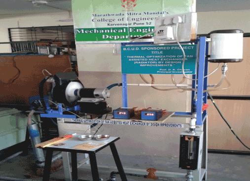
22 Fig Experimental Setup
 Anemometer")

23 Figure 3.18 (a) Anemometer Figure 3.18 (b) Anemometer Calibration Certificate
 Anemometer")
24 Figure 3.18 (c) Anemometer Calibration Certificate
 Infrared")
25 Figure 3.19 (a) Infrared Temperature Measuring Gun
 Infrared Temperature")
26 Figure 3.19 (b) Infrared Temperature Measuring Gun Calibration Certificate
27 3.12 BASIC RADIATOR DRAWING Fig : Vari ous Loc atio ns for Tem p and Velo citie s

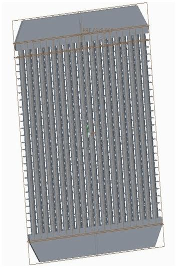
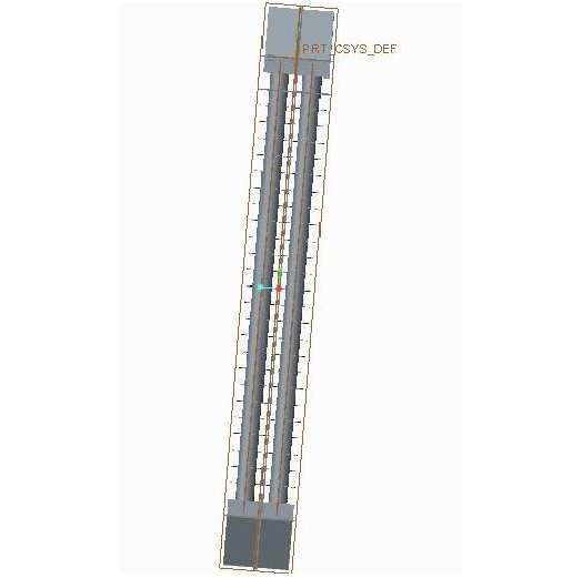
28 Fig. 3.21: Radiator CAD drawing
29 Fig. 3.22: Radiator with tube dimensions 3.13 GE OM ERI C MO DE LIN G OF FA N: For CFD anal ysis of the radia tor, it is necessary to create a geometric model of the system. A model of the radiator and the fan was made in CATIA V5 and then exported to CFD analysis software.

30 Fig.3.23 Fan Model
31 Fig.3.24 Radiator Models

32 PART: A SET: 1 Fig.3.: Temperature and Velocity reading NOTE1 : A,B,C,D,E,F,G,H,I,J,K,L,M,N,O,P are radial lines on Radiator on which temperature readings are taken and denoted by faint Numericals
33 NOTE2 : V1,V2,V3,V4,V5,V6,V7,V8 are radial lines on Radiator on which Velocity reading are taken and denoted by Dark Numerical Temperature Vs Radial Distance A B C D E 45 E F G H I 45 I J K L M A M N O P Fig.3.26 Temperature Vs Radial Distance for 100 lph & 1500 rpm
34 Velocity Vs Radial Distance V1 V2 V3 V4 V5 V6 V7 V8 0 Fig.3.27 Velocity Vs Radial Distance for 100 lph & 1500 rpm
35 SET: 2
36 Fig.3.28 Temperature and Velocity reading Temperature Vs Radial Distance 45 A B C D E 45 E F G H I 45 I J K L M A M N O P Fig.3.29 Temperature Vs Radial Distance for 110 lph & 1500 rpm
37 Velocity Vs Radial Distance V1 V2 V3 V4 V5 V6 V7 V8 Fig.3. Velocity Vs. Radial Distance for 110 lph & 1500 rpm
38 SET: 3 Fig.3.31 Temperature and Velocity reading
39 Temperature Vs Radial Distance A B C D E 45 E F G H I I J K L M A M N O P Fig.3.32 Temperature Vs Radial Distance for 120 lph & 1500 rpm
40 Velocity Vs Radial Distance V1 V2 V3 V4 V5 V6 V7 V8 Fig.3.33 Velocity Vs Radial Distance for 120 lph & 1500 rpm
41 SET: 4 Fig.3.34 Temperature and Velocity reading
42 Temperature Vs Radial Distance 45 A B C D E 45 E F G H I I J K L M A M N O P Fig.3. Temperature Vs Radial Distance for 1 lph & 1500 rpm
43 Velocity Vs Radial Distance V1 V2 V3 V4 V5 V6 V7 V8 Fig.3.36: Velocity Vs Radial Distance for 1 lph & 1500 rpm
44 SET: 5 Fig.3.37: Temperature and Velocity reading
45 Temperature Vs Radial Distance A B C D E E F G H I I J K L M M N O P A Fig.3.38 Temperature Vs Radial Distance for 1 lph & 1500 rpm
46 Velocity Vs Radial Distance V1 V2 V3 V4 V5 V6 V7 V8 0 Fig.3.39 Velocity vs. Radial Distance for 1 lph & 1500 rpm
47 SET: 6 Fig.3. Temperature and Velocity reading
48 Temperature Vs Radial Distance A B C D E 45 E F G H I I J K L M 45 A M N O P Fig.3.41 Temperature Vs Radial Distance for 150 lph & 1500 rpm
49 Velocity Vs Radial Distance V1 V2 V3 V4 V5 V6 V7 V8 0 Fig.3.42 Velocity Vs Radial Distance for 150 lph & 1500 rpm
50 SET: 7 Fig Temperature and Velocity reading
51 Temperature Vs Radial Distance A B C D E E F G H I I J K L M M N O P A Fig.3.44 Temperature Vs Radial Distance for 160 lph & 1500 rpm
52 Velocity Vs Radial Distance V1 V2 V3 V4 V5 V6 V7 V8 0 Fig Velocity Vs Radial Distance for 160 lph & 1500 rpm
53 SET: 8 Fig Temperature and Velocity reading
54 Temperature Vs Radial Distance 45 A B C D E E F G H I 45 I J K L M A M N O P Fig.3.47 Temperature Vs Radial Distance for 170 lph & 1500 rpm
55 Velocity Vs Radial Distance V1 V2 V3 V4 V5 V6 V7 V8 0 Fig.3.48 Velocity Vs Radial Distance for 170 lph & 1500 rpm
56 SET: 9 Fig Temperature and Velocity reading
57 Temperature Vs Radial Distance A B C D E 45 E F G H I 45 I J K L M M N O P A Fig.3.50 Temperature Vs Radial Distance for 180 lph & 1500 rpm
58 Velocity Vs Radial Distance V1 V2 V3 V4 V5 V6 V7 V8 0 Fig.3.51 Velocity Vs Radial Distance for 180 lph & 1500 rpm
59 SET: 10
60 Fig.3.52 Temperature and Velocity reading
61 Temperature Vs Radial Distance A B C D E E F G H I I J K L M A M N O P Fig.3.53 Temperature Vs Radial Distance for 190 lph & 1500 rpm
62 Velocity Vs Radial Distance V1 V2 V3 V4 V5 V6 V7 V8 0 Fig.3.54 Velocity Vs Radial Distance for 190 lph & 1500 rpm
63 SET: 11 Fig.3.55 Temperature and Velocity reading
64 Temperature Vs Radial Distance A B C D E E F G H I I J K L M M N O P A Fig.3.56 Temperature Vs Radial Distance for 200 lph & 1500 rpm
65 Velocity Vs Radial Distance V1 V2 2 V V4 V5 V6 V7 0 V8 Fig.3.57 Velocity Vs Radial Distance for 200 lph & 1500 rpm
66 Part: B Set: 1 Fig.3.58 Temperature and Velocity reading
67 Temperature Vs Radial Distance A B C D E E F G H I I J K L M M N O P A Fig.3.59 Temperature Vs Radial Distance for 100 lph & 1600 rpm
68 Velocity Vs Radial Distance V1 V2 V3 V4 V5 V6 V7 V8 0 Fig.3.60 Velocity Vs Radial Distance for 100 lph & 1600 rpm
69 Set: 2
70 Fig.3.61 Temperature and Velocity reading Temperature Vs Radial Distance A B C D E E F G H I 45 I J K L M M N O P A Fig.3.62 Temperature Vs Radial Distance for 100 lph & 1700 rpm
71 Velocity Vs Radial Distance V1 V2 V3 V4 V5 V6 V7 V8 0 Fig.3.63 Velocity Vs Radial Distance for 100 lph & 1700 rpm
72
73 Set: 3 Fig.3.64 Temperature and Velocity reading
74 Temperature Vs Radial Distance 45 A B C D E E F G H I 45 I J K L M M N O P A Fig.3.65 Temperature Vs Radial Distance for 100 lph & 1800 rpm
75 Velocity Vs Radial Distance V1 V2 V3 V4 V5 V6 V7 V8 0 Fig Velocity Vs Radial Distance for 100 lph & 1800 rpm
76 Set: 4
77 Fig Temperature and Velocity reading
78 Temperature Vs Radial Distance A B C D E E F G H I 45 I J K L M M N O P A Fig Temperature Vs Radial Distance for 100 lph & 1900 rpm
79 Velocity Vs Radial Distance V1 V2 V3 V4 V5 V6 V7 V8 0 Fig Velocity Vs Radial Distance for 100 lph & 1900 rpm
80 Set: 5
81 Fig.3.70 Temperature and Velocity reading Temperature Vs Radial Distance A B C D E E F G H I 45 I J K L M M N O P a
82 Fig.3.71 Temperature Vs Radial Distance for 100 lph & 2000 rpm Velocity Vs Radial Distance V1 V2 V3 V4 V5 V6 V7 V8 0 Fig.3.72 Velocity Vs Radial Distance for 100 lph & 2000 rpm
83 PA RT: C Set: 6 Fig Tempe rature and Veloci ty readin g Distance Te mpe ratu re Vs Rad ial
84 45 A B C D E 45 E F G H I I J K L M A M N O P Fig.3.74 Temperature Vs Radial Distance for 120 lph & 1600 rpm
85 Velocity Vs Radial Distance V1 V2 V3 V4 V5 V6 V7 V8 Fig Velocity Vs Radial Distance for 120 lph & 1600 rpm
86 Set: 7 Fig.3.76 Temperature and Velocity reading
87 Temperature Vs Radial Distance A B C D E 45 E F G H I I J K L M A M N O P Fig.3.77 Temperature Vs Radial Distance for 120 lph & 1700 rpm
88 Velocity Vs Radial Distance V1 V2 V3 V4 V5 V6 V7 V8 0 Fig.3.78 Velocity Vs Radial Distance for 120 lph & 1700 rpm
89 Set: 8
90 Fig.3.79 Temperature and Velocity reading Temperature Vs Radial Distance A B C D E E F G H I I J K L M A M N O P Fig.3.80 Temperature Vs Radial Distance for 120 lph & 1800 rpm
91 Velocity Vs Radial Distance V1 V2 V3 V4 V5 V6 V7 V8 0 Fig.3.81 Velocity Vs Radial Distance for 120 lph & 1800 rpm
92
93 Set: 9 Fig.3.82 Temperature and Velocity reading
94 Temperature Vs Radial Distance A B C D E 45 E F G H I I J K L M A M N O P Fig.3.83 Temperature Vs Radial Distance for 120 lph & 1900 rpm
95 Velocity Vs Radial Distance V1 V2 V3 V4 V5 V6 V7 V8 0 Fig.3.84 Velocity Vs Radial Distance for 120 lph & 1900 rpm
96 Set: 10
97 Fig.3.85 Temperature and Velocity reading Temperature Vs Radial Distance A B C D E E F G H I I J K L M A M N O P Fig.3.86 Temperature Vs Radial Distance for 120 lph & 2000 rpm
98 Velocity Vs Radial Distance V1 V2 V3 V4 V5 V6 V7 V8 0 Fig.3.87 Velocity Vs Radial Distance for 120 lph & 2000 rpm
99 PART: D
100 Set: 11 Fig.3.88 Temperature and Velocity reading
101 Temperature Vs Radial Distance A B C D E 45 E F G H I I J K L M A M N O P Fig.3.89 Temperature Vs Radial Distance for 1 lph & 1600 rpm
102 Velocity Vs Radial Distance V1 V2 V3 V4 V5 V6 V7 V8 0 Fig.3.90 Velocity Vs Radial Distance for 1 lph & 1600 rpm
103 Set: 12
104 Fig.3.91 Temperature and Velocity reading Temperature Vs Radial Distance A B C D E E F G H I I J K L M A M N O P
105 Fig.3.92 Temperature Vs Radial Distance for 1 lph & 1700 rpm 3.5 Velocity Vs Radial Distance V1 V2 V3 V4 V5 V6 V7 V8 0 Fig.3.93 Velocity Vs Radial Distance for 1 lph & 1700 rpm
106 Set: 13
107 Fig.3.94 Temperature and Velocity reading
108 Temperature Vs Radial Distance A B C D E 45 E F G H I I J K L M A M N O P Fig.3.95 Temperature Vs Radial Distance for 1 lph & 1800 rpm
109 Velocity Vs Radial Distance V1 V2 V3 V4 V5 V6 V7 V8 0 Fig.3.96 Velocity Vs Radial Distance for 1 lph 1800 rpm
110 Set: 14 Fig.3.97 Temperature and Velocity reading
111 Temperature Vs Radial Distance A B C D E E F G H I I J K L M A M N O P Fig.3.98 Temperature Vs Radial Distance for 1 lph & 1900 rpm
112 Velocity Vs Radial Distance V1 V2 V3 V4 V5 V6 V7 V8 Fig.3.99 Velocity Vs Radial Distance for 1 lph 1900 rpm
113 Set: 15
114 Fig Temperature and Velocity reading Temperature Vs Radial Distance A B C D E E F G H I I J K L M A M N O P Fig Temperature Vs Radial Distance 1 lph & 2000 rpm
115 Velocity Vs Radial Distance V1 V2 V3 V4 V5 V6 V7 V8 0 Fig Velocity Vs Radial Distance for 1 lph & 2000 rpm
116 PART: E Set: 16
117 Fig Temperature and Velocity reading Temperature Vs Radial Distance A B C D E 45 E F G H I I J K L M A M N O P
118 Fig Temperature Vs Radial Distance 160 lph & 1600 rpm 3.5 Velocity Vs Radial Distance V1 V2 V3 V4 V5 V6 V7 V8 0 Fig Velocity Vs Radial Distance for 160 lph & 1600 rpm
119 Set: 17
120 Fig Temperature and Velocity reading Temperature Vs Radial Distance A B C D E 45 E F G H I I J K L M A M N O P
121 Fig Temperature Vs Radial Distance 160 rpm & 1700 rpm 4 Velocity Vs Radial Distance V1 V2 V3 V4 V5 V6 V7 V8 Fig Velocity Vs Radial Distance for 160 lph & 1700 rpm
122 Set: 18
123 Fig Temperature and Velocity reading Temperature Vs Radial Distance 45 A B C D E 45 E F G H I I J K L M A M N O P
124 Fig Temperature Vs Radial Distance 160 lph & 1800 rpm Velocity Vs Radial Distance V1 V2 V3 V4 V5 V6 V7 V8 0 Fig Velocity Vs Radial Distance for 160 lph & 1800 rpm
125 Set: 19
126 Fig Temperature and Velocity reading
127 Temperature Vs Radial Distance A B C D E 45 E F G H I I J K L M A M N O P Fig Temperature Vs Radial Distance 160 lph & 1900 rpm
128 Velocity Vs Radial Distance V1 V2 V3 V4 V5 V6 V7 V8 0 Fig Velocity Vs Radial Distance for 160 lph & 1900 rpm
129 Set: 20 Fig Temperature and Velocity reading
130 Temperature Vs Radial Distance A B C D E 45 E F G H I I J K L M A M N O P Fig Temperature Vs Radial Distance 160 lph & 2000 rpm
131 Velocity Vs Radial Distance V1 V2 V3 V4 V5 V6 V7 V8 0 Fig Velocity Vs Radial Distance for 160 lph & 2000 rpm
132 PART: F Set: 21
133 Fig Temperature and Velocity reading Temperature Vs Radial Distance A B C D E E F G H I I J K L M A M N O P Fig Temperature Vs Radial Distance 180 lph & 1600 rpm
134 Velocity Vs Radial Distance V1 V2 V3 V4 V5 V6 V7 V8 0 Fig Velocity Vs Radial Distance for 180 lph & 1600 rpm
135 Set: 22
136 Fig Temperature and Velocity reading
137 Temperature Vs Radial Distance A B C D E E F G H I I J K L M A M N O P Fig Temperature Vs Radial Distance 180 lph & 1700 rpm
138 Velocity Vs Radial Distance V1 V2 V3 V4 V5 V6 V7 V8 0 Fig Velocity Vs Radial Distance for 180 lph & 1700 rpm
139
140 Set: 23
141 Fig Temperature and Velocity reading Temperature Vs Radial Distance A B C D E E F G H I I J K L M A M N O P Fig.3.1 Temperature Vs Radial Distance 180 lph & 1800 rpm
142 Velocity Vs Radial Distance V1 V2 V3 V4 V5 V6 V7 V8 0 Fig Velocity Vs Radial Distance for 180 lph & 1800 rpm
143 Set: 24
144 Fig Temperature and Velocity reading Temperature Vs Radial Distance A B C D E E F G H I I J K L M A M N O P
145 Fig Temperature Vs Radial Distance 180 lph & 1900 rpm Velocity Vs Radial Distance V1 V2 V3 V4 V5 V6 V7 V8 0 Fig Velocity Vs Radial Distance for 180 lph & 1900 rpm
146 Set:
147 Fig.3.1 Temperature and Velocity reading Temperature Vs Radial Distance
148 A B C D E E F G H I I J K L M A M N O P Fig Temperature Vs Radial Distance 180 lph & 2000 rpm
149 Velocity Vs Radial Distance V1 V2 V3 V4 V5 V6 V7 V Fig Velocity Vs Radial Distance for 180 lph & 2000 rpm
150 PART: G Set: 26 Fig Temperature and Velocity reading
151 Temperature Vs Radial Distance A B C D E E F G H I I J K L M 45 A M N O P Fig Temperature Vs Radial Distance 200 lph & 1600 rpm
152 Velocity Vs Radial Distance V1 V2 V3 V4 V5 V6 V7 V8 0 Fig.3.1 Velocity Vs Radial Distance for 200 lph & 1600 rpm
153 Set: 27
154 Fig Temperature and Velocity reading Temperature Vs Radial Distance A B C D E E F G H I I J K L M 45 A M N O P Fig Temperature Vs Radial Distance 200 lph & 1700 rpm
155 Velocity Vs Radial Distance V1 V2 V3 V4 V5 V6 V7 V8 0 Fig Velocity Vs Radial Distance for 200 lph & 1700 rpm
156 Set: 28
157 Fig Temperature and Velocity reading Temperature Vs Radial Distance A B C D E E F G H I I J K L M A M N O P Fig.3.1 Temperature Vs Radial Distance 200 lph & 1800 rpm
158 Velocity VS Radial Distance V1 V2 V3 V4 V5 V6 V7 V8 0 Fig Velocity Vs Radial Distance for 200 lph & 1800 rpm
159 Set: 29
160 Fig Temperature and Velocity reading Temperature Vs Radial Distance A B C D E E F G H I I J K L M A M N O P Fig Temperature Vs Radial Distance 200 lph & 1900 rpm
161 Velocity Vs Radial Distance V1 V2 V3 V4 V5 V6 V7 V8 0 Fig Velocity Vs Radial Distance 200 lph & 1900 rpm
162 Set:
163 Fig Temperature and Velocity reading Temperature Vs Radial Distance 45 A B C D E E F G H I I J K L M 45 A M N O P Fig Temperature Vs Radial Distance 200 lph & 2000 rpm
164 Velocity Vs Radial Distance V1 V2 V3 V4 V5 V6 V7 V Fig Velocity Vs Radial Distance for 200 lph & 2000 rpm
CHAPTER 7 NUMERICAL MODELLING OF A SPIRAL HEAT EXCHANGER USING CFD TECHNIQUE
 CHAPTER 7 NUMERICAL MODELLING OF A SPIRAL HEAT EXCHANGER USING CFD TECHNIQUE In this chapter, the governing equations for the proposed numerical model with discretisation methods are presented. Spiral
CFD ANALYSIS OF TRIANGULAR ABSORBER TUBE OF A SOLAR FLAT PLATE COLLECTOR
 Int. J. Mech. Eng. & Rob. Res. 2013 Basavanna S and K S Shashishekar, 2013 Research Paper ISSN 2278 0149 www.imerr.com Vol. 2, No. 1, January 2013 2013 IJMERR. All Rights Reserved CFD ANALYSIS OF TRIANGULAR
Performance characteristics of turbo blower in a refuse collecting system according to operation conditions
 Journal of Mechanical Science and Technology 22 (2008) 1896~1901 Journal of Mechanical Science and Technology www.springerlink.com/content/1738-494x DOI 10.1007/s12206-008-0729-6 Performance characteristics
Applied CFD Project 1. Christopher Light MAE 598
 Applied CFD Project 1 Christopher Light MAE 598 October 5, 2017 Task 1 The hot water tank shown in Fig 1 is used for analysis of cool water flow with the heat from a hot plate at the bottom. For all tasks,
FLUID FLOW AND HEAT TRANSFER INVESTIGATION OF PERFORATED HEAT SINK UNDER MIXED CONVECTION 1 Mr. Shardul R Kulkarni, 2 Prof.S.Y.
 FLUID FLOW AND HEAT TRANSFER INVESTIGATION OF PERFORATED HEAT SINK UNDER MIXED CONVECTION 1 Mr. Shardul R Kulkarni, 2 Prof.S.Y.Bhosale 1 Research scholar, 2 Head of department & Asst professor Department
International Journal of Scientific & Engineering Research, Volume 6, Issue 5, May ISSN
 International Journal of Scientific & Engineering Research, Volume 6, Issue 5, May-2015 28 CFD BASED HEAT TRANSFER ANALYSIS OF SOLAR AIR HEATER DUCT PROVIDED WITH ARTIFICIAL ROUGHNESS Vivek Rao, Dr. Ajay
Investigation of Jet Impingement on Flat Plate Using Triangular and Trapezoid Vortex Generators
 ISSN 2395-1621 Investigation of Jet Impingement on Flat Plate Using Triangular and Trapezoid Vortex Generators #1 Sonali S Nagawade, #2 Prof. S Y Bhosale, #3 Prof. N K Chougule 1 Sonalinagawade1@gmail.com
[Maddu, 5(12): December2018] ISSN DOI /zenodo Impact Factor
![[Maddu, 5(12): December2018] ISSN DOI /zenodo Impact Factor](/thumbs/92/109637914.jpg "[Maddu, 5(12): December2018] ISSN DOI /zenodo Impact Factor") GLOBAL JOURNAL OF ENGINEERING SCIENCE AND RESEARCHES ANALYSIS OF RADIATOR FAN OF WDM-2 LOCO ENGINE FOR EFFICIENCY IMPROVEMENT Yesu Ratnam. Maddu *1, K.Divakara Murthy 2 & Shaik Saidulu 3 *1,3 Assistant
GLOBAL JOURNAL OF ENGINEERING SCIENCE AND RESEARCHES ANALYSIS OF RADIATOR FAN OF WDM-2 LOCO ENGINE FOR EFFICIENCY IMPROVEMENT Yesu Ratnam. Maddu *1, K.Divakara Murthy 2 & Shaik Saidulu 3 *1,3 Assistant
report: Computational Fluid Dynamics Modelling of the Vortex Ventilator MK4 Rev 2 Ventrite International
 report: Computational Fluid Dynamics Modelling of the Vortex Ventilator MK4 Rev 2 PrePAreD for: Ventrite International D O C U men t C O N trol Any questions regarding this document should be directed
Comparative Analysis of Heat Transfer and Friction Characteristics in a Corrugated Tube
 International Journal of Current Engineering and Technology E-ISSN 2277 416, P-ISSN 2347 5161 216 INPRESSCO, All Rights Reserved Available at http://inpressco.com/category/ijcet Research Article Comparative
Performance Investigation of High Pressure Ratio Centrifugal Compressor using CFD
 International Journal of Ignited Minds (IJIMIINDS) Performance Investigation of High Pressure Ratio Centrifugal Compressor using CFD Manjunath DC a, Rajesh b, Dr.V.M.Kulkarni c a PG student, Department
COMPUTATIONAL FLUID DYNAMICS ANALYSIS OF A V-RIB WITH GAP ROUGHENED SOLAR AIR HEATER
 THERMAL SCIENCE: Year 2018, Vol. 22, No. 2, pp. 963-972 963 COMPUTATIONAL FLUID DYNAMICS ANALYSIS OF A V-RIB WITH GAP ROUGHENED SOLAR AIR HEATER by Jitesh RANA, Anshuman SILORI, Rajesh MAITHANI *, and
INTERNATIONAL JOURNAL OF SCIENTIFIC & TECHNOLOGY RESEARCH VOLUME 5, ISSUE 09, SEPTEMBER 2016 ISSN
 Numerical Analysis Of Heat Transfer And Fluid Flow Characteristics In Different V-Shaped Roughness Elements On The Absorber Plate Of Solar Air Heater Duct Jitesh Rana, Anshuman Silori, Rohan Ramola Abstract:
International Journal of Engineering Research and General Science Volume 3, Issue 6, November-December, 2015 ISSN
 NUMERICAL AND EXPERIMENTAL INVESTIGATION OF STAGGERED INTERRUPTED FIN ARRANGEMENT IN A NATURAL CONVECTION FIELD Mr.Bhushan S Rane 1, Prof. M D Shende 2 1 (P G Student, Department of Mechanical Engineering,
Enhancement of Heat Transfer Effectiveness of Plate-pin fin heat sinks With Central hole and Staggered positioning of Pin fins
 Enhancement of Heat Transfer Effectiveness of Plate-pin fin heat sinks With Central hole and Staggered positioning of Pin fins Jubin Jose 1, Reji Mathew 2 1Student, Dept. of Mechanical Engineering, M A
HEAT TRANSFER CAPABILITY OF A THERMOSYPHON HEAT TRANSPORT DEVICE WITH EXPERIMENTAL AND CFD STUDIES
 HEAT TRANSFER CAPABILITY OF A THERMOSYPHON HEAT TRANSPORT DEVICE WITH EXPERIMENTAL AND CFD STUDIES B.M. Lingade a*, Elizabeth Raju b, A Borgohain a, N.K. Maheshwari a, P.K.Vijayan a a Reactor Engineering
CFD Analysis of Forced Convection Flow and Heat Transfer in Semi-Circular Cross-Sectioned Micro-Channel
 CFD Analysis of Forced Convection Flow and Heat Transfer in Semi-Circular Cross-Sectioned Micro-Channel *1 Hüseyin Kaya, 2 Kamil Arslan 1 Bartın University, Mechanical Engineering Department, Bartın, Turkey
Numerical Analysis of Fluid Flow and Heat Transfer Characteristics of Ventilated Disc Brake Rotor Using CFD
 International Journal of Engineering Inventions e-issn: 2278-7461, p-issn: 2319-6491 Volume 4, Issue 10 [June 2015] PP: 31-38 Numerical Analysis of Fluid Flow and Heat Transfer Characteristics of Ventilated
AN UNCERTAINTY ESTIMATION EXAMPLE FOR BACKWARD FACING STEP CFD SIMULATION. Abstract
 nd Workshop on CFD Uncertainty Analysis - Lisbon, 19th and 0th October 006 AN UNCERTAINTY ESTIMATION EXAMPLE FOR BACKWARD FACING STEP CFD SIMULATION Alfredo Iranzo 1, Jesús Valle, Ignacio Trejo 3, Jerónimo
Project #1 Internal flow with thermal convection
 Project #1 Internal flow with thermal convection MAE 494/598, Fall 2017, Project 1 (20 points) Hard copy of report is due at the start of class on the due date. The rules on collaboration will be released
Numerical analysis of fluid flow and heat transfer in 2D sinusoidal wavy channel
 Numerical analysis of fluid flow and heat transfer in 2D sinusoidal wavy channel Arunanshu Chakravarty 1* 1 CTU in Prague, Faculty of Mechanical Engineering, Department of Process Engineering,Technická
COMPUTATIONAL ANALYSIS OF LAMINAR FORCED CONVECTION IN RECTANGULAR ENCLOSURES OF DIFFERENT ASPECT RATIOS
 HEFAT214 1 th International Conference on Heat Transfer, Fluid Mechanics and Thermodynamics 14 16 July 214 Orlando, Florida COMPUTATIONAL ANALYSIS OF LAMINAR FORCED CONVECTION IN RECTANGULAR ENCLOSURES
CHAPTER 4 OPTIMIZATION OF COEFFICIENT OF LIFT, DRAG AND POWER - AN ITERATIVE APPROACH
 82 CHAPTER 4 OPTIMIZATION OF COEFFICIENT OF LIFT, DRAG AND POWER - AN ITERATIVE APPROACH The coefficient of lift, drag and power for wind turbine rotor is optimized using an iterative approach. The coefficient
EFFECTIVENESS OF HEAT TRANSFER INTENSIFIERS IN A FLUID CHANNEL
 International Journal of Mechanical Engineering and Technology (IJMET) Volume 9, Issue 9, September 2018, pp. 58 62, Article ID: IJMET_09_09_007 Available online at http://www.iaeme.com/ijmet/issues.asp?jtype=ijmet&vtype=9&itype=9
CFD ANALYSIS OF CD NOZZLE AND EFFECT OF NOZZLE PRESSURE RATIO ON PRESSURE AND VELOCITY FOR SUDDENLY EXPANDED FLOWS. Kuala Lumpur, Malaysia
 International Journal of Mechanical and Production Engineering Research and Development (IJMPERD) ISSN(P): 2249-6890; ISSN(E): 2249-8001 Vol. 8, Issue 3, Jun 2018, 1147-1158 TJPRC Pvt. Ltd. CFD ANALYSIS
ABSTRACT I. INTRODUCTION
 2016 IJSRSET Volume 2 Issue 4 Print ISSN : 2395-1990 Online ISSN : 2394-4099 Themed Section: Engineering and Technology Analysis of Compressible Effect in the Flow Metering By Orifice Plate Using Prasanna
Prediction of Performance Characteristics of Orifice Plate Assembly for Non-Standard Conditions Using CFD
 International Journal of Engineering and Technical Research (IJETR) ISSN: 2321-0869, Volume-3, Issue-5, May 2015 Prediction of Performance Characteristics of Orifice Plate Assembly for Non-Standard Conditions
Simplified Model of WWER-440 Fuel Assembly for ThermoHydraulic Analysis
 1 Portál pre odborné publikovanie ISSN 1338-0087 Simplified Model of WWER-440 Fuel Assembly for ThermoHydraulic Analysis Jakubec Jakub Elektrotechnika 13.02.2013 This work deals with thermo-hydraulic processes
This chapter focuses on the study of the numerical approximation of threedimensional
 6 CHAPTER 6: NUMERICAL OPTIMISATION OF CONJUGATE HEAT TRANSFER IN COOLING CHANNELS WITH DIFFERENT CROSS-SECTIONAL SHAPES 3, 4 6.1. INTRODUCTION This chapter focuses on the study of the numerical approximation
Keywords - Gas Turbine, Exhaust Diffuser, Annular Diffuser, CFD, Numerical Simulations.
 Numerical Investigations of PGT10 Gas Turbine Exhaust Diffuser Using Hexahedral Dominant Grid Vaddin Chetan, D V Satish, Dr. Prakash S Kulkarni Department of Mechanical Engineering, VVCE, Mysore, Department
Department of Energy Science & Engineering, IIT Bombay, Mumbai, India. *Corresponding author: Tel: ,
 ICAER 2011 AN EXPERIMENTAL AND COMPUTATIONAL INVESTIGATION OF HEAT LOSSES FROM THE CAVITY RECEIVER USED IN LINEAR FRESNEL REFLECTOR SOLAR THERMAL SYSTEM Sudhansu S. Sahoo* a, Shinu M. Varghese b, Ashwin
International Journal of Engineering Trends and Technology (IJETT) Volume 49 Number 6 July 2017
 Volume 49 Number 6 July 2017") Effect of Divergence Angle on the Performance and Flow Analysis of 3D Annular Diffuser of an Aircraft Engine using CFD Technique Sharan Padashetty 1, Pravin Honguntikar 2, K. Rajagopal 3 1 Ph.D Research
Effect of Divergence Angle on the Performance and Flow Analysis of 3D Annular Diffuser of an Aircraft Engine using CFD Technique Sharan Padashetty 1, Pravin Honguntikar 2, K. Rajagopal 3 1 Ph.D Research
MAE 598 Project #1 Jeremiah Dwight
 MAE 598 Project #1 Jeremiah Dwight OVERVIEW A simple hot water tank, illustrated in Figures 1 through 3 below, consists of a main cylindrical tank and two small side pipes for the inlet and outlet. All
FLOW PATTERN STUDY OF A CENTRIFUGAL PUMP USING CFD METHODS CONCENTRATING ON VOLUTE TONGUE ROLE
 FLOW PATTERN STUDY OF A CENTRIFUGAL PUMP USING CFD METHODS CONCENTRATING ON VOLUTE TONGUE ROLE N. Pourmahmoud and S. Majid Taleby Faculty of Engineering, Urmia University, Urmia, Iran E-Mail: majid.taleby@gmail.com
FLOW AND HEAT TRANSFER ANALYSIS OF VARIOUS RIBS FOR FORCED CONVECTION HEAT TRANSFER
 FLOW AND HEAT TRANSFER ANALYSIS OF VARIOUS RIBS FOR FORCED CONVECTION HEAT TRANSFER 1 Navanath.G.Ghodake, 2 Prof.MRC. Rao, 3 Dr. R. R. Arakerimath 1 ME heat power student, 2 professor, 3 Professor & Dean
DESIGN AND CFD ANALYSIS OF A CENTRIFUGAL PUMP
 DESIGN AND CFD ANALYSIS OF A CENTRIFUGAL PUMP 1 CH.YADAGIRI, 2 P.VIJAYANAND 1 Pg Scholar, Department of MECH, Holymary Institute of Technology, Ranga Reddy, Telangana, India. 2 Assistant Professor, Department
Laminar flow heat transfer studies in a twisted square duct for constant wall heat flux boundary condition
 Sādhanā Vol. 40, Part 2, April 2015, pp. 467 485. c Indian Academy of Sciences Laminar flow heat transfer studies in a twisted square duct for constant wall heat flux boundary condition RAMBIR BHADOURIYA,
COMPUTATIONAL FLOW ANALYSIS THROUGH A DOUBLE-SUCTION IMPELLER OF A CENTRIFUGAL PUMP
 Proceedings of the Fortieth National Conference on Fluid Mechanics and Fluid Power December 12-14, 2013, NIT Hamirpur, Himachal Pradesh, India FMFP2013_141 COMPUTATIONAL FLOW ANALYSIS THROUGH A DOUBLE-SUCTION
EFFECT OF DISTRIBUTION OF VOLUMETRIC HEAT GENERATION ON MODERATOR TEMPERATURE DISTRIBUTION
 EFFECT OF DISTRIBUTION OF VOLUMETRIC HEAT GENERATION ON MODERATOR TEMPERATURE DISTRIBUTION A. K. Kansal, P. Suryanarayana, N. K. Maheshwari Reactor Engineering Division, Bhabha Atomic Research Centre,
Computational Fluid Dynamics Based Analysis of Angled Rib Roughened Solar Air Heater Duct
 Research Article International Journal of Thermal Technologies ISSN 2277-4114 2013 INPRESSCO. All Rights Reserved. Available at http://inpressco.com/category/ijtt Computational Fluid Dynamics Based Analysis
This section develops numerically and analytically the geometric optimisation of
 7 CHAPTER 7: MATHEMATICAL OPTIMISATION OF LAMINAR-FORCED CONVECTION HEAT TRANSFER THROUGH A VASCULARISED SOLID WITH COOLING CHANNELS 5 7.1. INTRODUCTION This section develops numerically and analytically
A CFD Analysis Of A Solar Air Heater Having Triangular Rib Roughness On The Absorber Plate
 International Journal of ChemTech Research CODEN( USA): IJCRGG ISSN : 0974-4290 Vol.5, No.2, pp 964-971, April-June 2013 ICGSEE-2013[14th 16th March 2013] International Conference on Global Scenario in
THE EFFECT OF TWO PHASE (AIR-WATER) FLOW CHARACTERISTICS ON MOMENTUM FLUX DUE TO FLOW TURNING ELEMENTS AT ATMOSPHERIC CONDITIONS
 FLOW CHARACTERISTICS ON MOMENTUM FLUX DUE TO FLOW TURNING ELEMENTS AT ATMOSPHERIC CONDITIONS") International Journal of Latest Trends in Engineering and Technology Vol.(8)Issue(1), pp.319-328 DOI: http://dx.doi.org/10.21172/1.81.041 e-issn:2278-621x AN EXPERIMENTAL STUDY OF THE EFFECT OF TWO PHASE
International Journal of Latest Trends in Engineering and Technology Vol.(8)Issue(1), pp.319-328 DOI: http://dx.doi.org/10.21172/1.81.041 e-issn:2278-621x AN EXPERIMENTAL STUDY OF THE EFFECT OF TWO PHASE
midas NFX 2015 R1 Release Note
 Total Solution for True Analysis-driven Design midas NFX 2015 R1 Release Note 1 midas NFX R E L E A S E N O T E 2 0 1 5 R 1 Accurate whenever you Need Be more efficient by focusing on the right details
Analysis of the Cooling Design in Electrical Transformer
 Analysis of the Cooling Design in Electrical Transformer Joel de Almeida Mendes E-mail: joeldealmeidamendes@hotmail.com Abstract This work presents the application of a CFD code Fluent to simulate the
Basic Fluid Mechanics
 Basic Fluid Mechanics Chapter 3B: Conservation of Mass C3B: Conservation of Mass 1 3.2 Governing Equations There are two basic types of governing equations that we will encounter in this course Differential
SIMULATION OF THERMAL CHARACTERISTICS OF RADIATORS USING A POROUS MODEL. YETSAN Auto Radiator Co. Inc Çorum, Turkey NOMENCLATURE
 Proceedings of CONV-14: Int. Symp. on ConvectiveHeatandMass Transfer June8 13, 2014, Turkey CONV-14 176 SIMULATION OF THERMAL CHARACTERISTICS OF RADIATORS USING A POROUS MODEL Kadir G. Güler 1,2 and BarbarosÇetin
CFD Analysis of Multi-jet Air Impingement on Flat Plate
 , July 6-8, 2011, London, U.K. CFD Analysis of Multi-jet Air Impingement on Flat Plate Chougule N.K., Parishwad G.V., Gore P.R., Pagnis S., Sapali S.N. Abstract Jet impingement is one of the intensive
Numerical Analysis of Tube-Fin Heat Exchanger using Fluent
 Numerical Analysis of Tube-Fin Heat Exchanger using Fluent M. V. Ghori & R. K. Kirar Patel college of Science and Technology, Rajiv Gandhi Proudyogiki Vishwavidhyalaya, Ratibad, Bhopal- 462036, India E-mail
THERMAL ANALYSIS OF SECOND STAGE GAS TURBINE ROTOR BLADE
 Polymers Research Journal ISSN: 195-50 Volume 6, Number 01 Nova Science Publishers, Inc. THERMAL ANALYSIS OF SECOND STAGE GAS TURBINE ROTOR BLADE E. Poursaeidi, M. Mohammadi and S. S. Khamesi University
Modeling and analysis of brake drum with extended fins on the
 Research Journal of Engineering Sciences ISSN 2278 9472 Modeling and analysis of brake drum with extended fins on the circumference of drum to improve heat dissipation: a CFD approach Abstract Yogeshwar
Flow analysis in centrifugal compressor vaneless diffusers
 348 Journal of Scientific & Industrial Research J SCI IND RES VOL 67 MAY 2008 Vol. 67, May 2008, pp. 348-354 Flow analysis in centrifugal compressor vaneless diffusers Ozturk Tatar, Adnan Ozturk and Ali
CFD AND CONJUGATE HEAT TRANSFER ANALYSIS OF HEAT SINKS WITH DIFFERENT FIN GEOMETRIES SUBJECTED TO FORCED CONVECTION USED IN ELECTRONICS COOLING
 CFD AND CONJUGATE HEAT TRANSFER ANALYSIS OF HEAT SINKS WITH DIFFERENT FIN GEOMETRIES SUBJECTED TO FORCED CONVECTION USED IN ELECTRONICS COOLING V. M Kulkarni 1, Basavaraj Dotihal 2 1 Professor, Thermal
CFD Analysis on Flow Through Plate Fin Heat Exchangers with Perforations
 CFD Analysis on Flow Through Plate Fin Heat Exchangers with Perforations 1 Ganapathi Harish, 2 C.Mahesh, 3 K.Siva Krishna 1 M.Tech in Thermal Engineering, Mechanical Department, V.R Siddhartha Engineering
Signature: (Note that unsigned exams will be given a score of zero.)
") Neatly print your name: Signature: (Note that unsigned exams will be given a score of zero.) Circle your lecture section (-1 point if not circled, or circled incorrectly): Prof. Dabiri Prof. Wassgren Prof.
Neatly print your name: Signature: (Note that unsigned exams will be given a score of zero.) Circle your lecture section (-1 point if not circled, or circled incorrectly): Prof. Dabiri Prof. Wassgren Prof.
Experimental and CFD analysis of flow through venturimeter to determine the coefficient of discharge
 Experimental and CFD analysis of flow through venturimeter to determine the coefficient of discharge Nikhil Tamhankar Amar Pandhare Ashwinkumar Joglekar Vaibhav Bansode Abstract- The pressure distribution
SHELL SIDE NUMERICAL ANALYSIS OF A SHELL AND TUBE HEAT EXCHANGER CONSIDERING THE EFFECTS OF BAFFLE INCLINATION ANGLE ON FLUID FLOW
 THERMAL SCIENCE: Year 2012, Vol. 16, No. 4, pp. 1165-1174 1165 SHELL SIDE NUMERICAL ANALYSIS OF A SHELL AND TUBE HEAT EXCHANGER CONSIDERING THE EFFECTS OF BAFFLE INCLINATION ANGLE ON FLUID FLOW by Rajagapal
Numerical Study of the Three-dimensional Flow in a Flat Plate Solar Collector with Baffles
 Numerical Study of the Three-dimensional Flow in a Flat Plate Solar Collector with Baffles M.A. AMRAOUI a, K. ALIANE b a. Department of Mechanical Engineering, Faculty of Technology, University of Tlemcen,
Numerical investigation of swirl flow inside a supersonic nozzle
 Advances in Fluid Mechanics IX 131 Numerical investigation of swirl flow inside a supersonic nozzle E. Eslamian, H. Shirvani & A. Shirvani Faculty of Science and Technology, Anglia Ruskin University, UK
Study on residence time distribution of CSTR using CFD
 Indian Journal of Chemical Technology Vol. 3, March 16, pp. 114-1 Study on residence time distribution of CSTR using CFD Akhilesh Khapre*, Divya Rajavathsavai & Basudeb Munshi Department of Chemical Engineering,
FLOW MALDISTRIBUTION IN A SIMPLIFIED PLATE HEAT EXCHANGER MODEL - A Numerical Study
 FLOW MALDISTRIBUTION IN A SIMPLIFIED PLATE HEAT EXCHANGER MODEL - A Numerical Study Nityanand Pawar Mechanical Engineering, Sardar Patel College of Engineering, Mumbai, Maharashtra, India nitya.pawar@gmail.com
Comparison of heat transfer characteristics of liquid coolants in forced convection cooling in a micro heat sink
 Nivesh Agrawal et al. / IJAIR ISSN: 78-7844 Comparison of heat transfer characteristics of liquid coolants in forced convection cooling in a micro heat sink Mr.Nivesh Agrawal #1 Mr.Mahesh Dewangan * #1
CFD study for cross flow heat exchanger with integral finned tube
 International Journal of Scientific and Research Publications, Volume 6, Issue 6, June 2016 668 CFD study for cross flow heat exchanger with integral finned tube Zena K. Kadhim *, Muna S. Kassim **, Adel
Numerical Analysis of Fe 3 O 4 Nanofluid Flow in a Double Pipe U-Bend Heat Exchanger
 International Journal of Engineering Studies. ISSN 0975-6469 Volume 8, Number 2 (2016), pp. 211-224 Research India Publications http://www.ripublication.com Numerical Analysis of Fe 3 O 4 Nanofluid Flow
DEVELOPED LAMINAR FLOW IN PIPE USING COMPUTATIONAL FLUID DYNAMICS M.
 DEVELOPED LAMINAR FLOW IN PIPE USING COMPUTATIONAL FLUID DYNAMICS M. Sahu 1, Kishanjit Kumar Khatua and Kanhu Charan Patra 3, T. Naik 4 1, &3 Department of Civil Engineering, National Institute of technology,
Thermo-Hydraulic performance of Internal finned tube Automobile Radiator
 Thermo-Hydraulic performance of Internal finned tube Automobile Radiator Dr.Kailash Mohapatra 1, Deepiarani Swain 2 1 Department of Mechanical Engineering, Raajdhani Engineering College, Bhubaneswar, 751017,
Numerical Investigation of Convective Heat Transfer in Pin Fin Type Heat Sink used for Led Application by using CFD
 GRD Journals- Global Research and Development Journal for Engineering Volume 1 Issue 8 July 2016 ISSN: 2455-5703 Numerical Investigation of Convective Heat Transfer in Pin Fin Type Heat Sink used for Led
Numerical investigation of solid-liquid two phase flow in a non-clogging centrifugal pump at offdesign
 IOP Conference Series: Earth and Environmental Science Numerical investigation of solid-liquid two phase flow in a non-clogging centrifugal pump at offdesign conditions To cite this article: B J Zhao et
CFD in Heat Transfer Equipment Professor Bengt Sunden Division of Heat Transfer Department of Energy Sciences Lund University
 CFD in Heat Transfer Equipment Professor Bengt Sunden Division of Heat Transfer Department of Energy Sciences Lund University email: bengt.sunden@energy.lth.se CFD? CFD = Computational Fluid Dynamics;
Numerical Analysis of a Helical Coiled Heat Exchanger using CFD
 International Journal of Thermal Technologies ISSN 2277-4114 213 INPRESSCO. All Rights Reserved. Available at http://inpressco.com/category/ijtt Research Article Numerical Analysis of a Helical Coiled
QUALIFICATION OF A CFD CODE FOR REACTOR APPLICATIONS
 QUALIFICATION OF A CFD CODE FOR REACTOR APPLICATIONS Ulrich BIEDER whole TrioCFD Team DEN-STMF, CEA, UNIVERSITÉ PARIS-SACLAY www.cea.fr SÉMINAIRE ARISTOTE, NOVEMBER 8, 2016 PAGE 1 Outline Obective: analysis
Experimental Verification of CFD Modeling of Turbulent Flow over Circular Cavities using FLUENT
 Experimental Verification of CFD Modeling of Turbulent Flow over Circular Cavities using FLUENT T Hering, J Dybenko, E Savory Mech. & Material Engineering Dept., University of Western Ontario, London,
CFD ANALYSIS OF PRESSURE DISTRIBUTION IN SLIDE CONICAL BEARING LUBRICATED WITH NON-NEWTONIAN OIL
 Journal of KONES Powertrain and Transport, Vol. 20, No. 3 2013 CFD ANALYSIS OF PRESSURE DISTRIBUTION IN SLIDE CONICAL BEARING LUBRICATED WITH NON-NEWTONIAN OIL Adam Czaban Gdynia Maritime University Faculty
TABLE OF CONTENTS CHAPTER TITLE PAGE
 v TABLE OF CONTENTS CHAPTER TITLE PAGE TABLE OF CONTENTS LIST OF TABLES LIST OF FIGURES LIST OF SYMBOLS LIST OF APPENDICES v viii ix xii xiv CHAPTER 1 INTRODUCTION 1.1 Introduction 1 1.2 Literature Review
CFD Analysis of Mixing in Polymerization Reactor. By Haresh Patel Supervisors: Dr. R. Dhib & Dr. F. Ein-Mozaffari IPR 2007
 CFD Analysis of Mixing in Polymerization Reactor By Haresh Patel Supervisors: Dr. R. Dhib & Dr. F. Ein-Mozaffari Introduction Model development Simulation Outline Model Setup for Fluent Results and discussion
Numerical Simulation of Supersonic Expansion in Conical and Contour Nozzle
 Numerical Simulation of Supersonic Expansion in Conical and Contour Nozzle Madhu B P (1), Vijaya Raghu B (2) 1 M.Tech Scholars, Mechanical Engineering, Maharaja Institute of Technology, Mysore 2 Professor,
EVALUATION OF FOUR TURBULENCE MODELS IN THE INTERACTION OF MULTI BURNERS SWIRLING FLOWS
 EVALUATION OF FOUR TURBULENCE MODELS IN THE INTERACTION OF MULTI BURNERS SWIRLING FLOWS A Aroussi, S Kucukgokoglan, S.J.Pickering, M.Menacer School of Mechanical, Materials, Manufacturing Engineering and
Numerical analysis of three-lobe journal bearing with CFD and FSI
 Numerical analysis of three-lobe journal bearing with CFD and FSI Pankaj Khachane 1, Dinesh Dhande 2 1PG Student at Department of Mechanical Engineering, AISSMSCOE Pune, Maharashtra, India 2Assistant Professor
CFD and Thermal Stress Analysis of Helium-Cooled Divertor Concepts
 CFD and Thermal Stress Analysis of Helium-Cooled Divertor Concepts Presented by: X.R. Wang Contributors: R. Raffray and S. Malang University of California, San Diego ARIES-TNS Meeting Georgia Institute
THERMAL PERFORMANCE EVALUATION OF AN INNOVATIVE DOUBLE GLAZING WINDOW
 THERMAL PERFORMANCE EVALUATION OF AN INNOVATIVE DOUBLE GLAZING WINDOW Luigi De Giorgi, Carlo Cima, Emilio Cafaro Dipartimento di Energetica, Politecnico di Torino, Torino, Italy Volfango Bertola School
Flow Distribution inside an Electrostatic Precipitator: Effects of Uniform and Variable Porosity of Perforated Plate
 Proceedings of the 5th IASME/WSEAS Int. Conference on Heat Transfer, Thermal Engineering and Environment, Athens, Greece, August 5-7, 7 6 Flow Distribution inside an Electrostatic Precipitator: Effects
PERFORMANCE SCREENING OF A LOUVERED FIN AND VORTEX GENERATOR COMBINATION
 HEFAT2014 10 th International Conference on Heat Transfer, Fluid Mechanics and Thermodynamics 14 26 July 2014 Orlando, Florida PERFORMANCE SCREENING OF A LOUVERED FIN AND VORTEX GENERATOR COMBINATION Bernd
Natural Convection from Horizontal Rectangular Fin Arrays within Perforated Chassis
 Proceedings of the 2 nd International Conference on Fluid Flow, Heat and Mass Transfer Ottawa, Ontario, Canada, April 30 May 1, 2015 Paper No. 146 Natural Convection from Horizontal Rectangular Fin Arrays
NUMERICAL SIMULATION ON RECTANGULAR CONVERGENT AND DIVERGENT RIBBED CHANNELS
 NUMERICAL SIMULATION ON RECTANGULAR CONVERGENT AND DIVERGENT RIBBED CHANNELS K. Sivakumar 1, E. Natarajan and N. Kulasekharan 3 1 Valliammai Engineering College, Chennai, India Institute of Energy Studies,
Performance Improvement of S-shaped Diffuser Using Momentum Imparting Technique
 IOSR Journal of Mechanical and Civil Engineering (IOSR-JMCE) e-issn: 2278-1684,p-ISSN: 2320-334X, Volume 11, Issue 3 Ver. I (May- Jun. 2014), PP 23-31 Performance Improvement of S-shaped Diffuser Using
COMPUTATIONAL SIMULATION OF THE FLOW PAST AN AIRFOIL FOR AN UNMANNED AERIAL VEHICLE
 COMPUTATIONAL SIMULATION OF THE FLOW PAST AN AIRFOIL FOR AN UNMANNED AERIAL VEHICLE L. Velázquez-Araque 1 and J. Nožička 2 1 Division of Thermal fluids, Department of Mechanical Engineering, National University
Numerical Analysis of Helical Coil Heat Exchanger in the Light of Waste Heat Recovery Applications
 Numerical Analysis of Helical Coil Heat Exchanger in the Light of Waste Heat Recovery Applications Mukesh Sharma 1, Jagdeesh Saini 2 1 M-Tech Student, 2 Assistant Professor B M College of Technology, Indore,
Effect of modification to tongue and basic circle diameter on vibration in a double-suction centrifugal pump
 5th International Conference on Information Engineering for Mechanics and Materials (ICIMM 2015) Effect of modification to tongue and basic circle diameter on vibration in a double-suction centrifugal
INTERNATIONAL JOURNAL OF APPLIED ENGINEERING RESEARCH, DINDIGUL Volume 2, No 1, 2011
 Experimental and Numerical comparison between the performance of Helical cone coils and ordinary helical coils used as dehumidifier for humidification dehumidification in desalination units Abo Elazm M.M.
COMPUTATIONAL FLUID DYNAMICS ON DIFFERENT PASSAGES OVER A PLATE COIL EVAPORATOR FOR 40 LITER STORAGE TYPE WATER COOLER
 Int. J. Mech. Eng. & Rob. Res. 2014 Mukund Y Pande and Atul Patil, 2014 Research Paper ISSN 2278 0149 www.ijmerr.com Vol. 3, No. 4, October 2014 2014 IJMERR. All Rights Reserved COMPUTATIONAL FLUID DYNAMICS
INFLUENCE OF VAPOR FEED DESIGN ON THE FLOW DISTRIBUTION
 INFLUENCE OF VAPOR FEED DESIGN ON THE FLOW DISTRIBUTION M. Wehrli *, S. Hirschberg**, R. Schweizer** * Sulzer Chemtech AG, Postfach, CH-8404 Winterthur, Switzerland ** Sulzer Innotec AG, Postfach, CH-8401
Department of Engineering and System Science, National Tsing Hua University,
 3rd International Conference on Materials Engineering, Manufacturing Technology and Control (ICMEMTC 2016) The Establishment and Application of TRACE/CFD Model for Maanshan PWR Nuclear Power Plant Yu-Ting
Analysis of Heat Transfer in Pipe with Twisted Tape Inserts
 Proceedings of the 2 nd International Conference on Fluid Flow, Heat and Mass Transfer Ottawa, Ontario, Canada, April 30 May 1, 2015 Paper No. 143 Analysis of Heat Transfer in Pipe with Twisted Tape Inserts
CFD Analysis for Thermal Behavior of Turbulent Channel Flow of Different Geometry of Bottom Plate
 International Journal Of Engineering Research And Development e-issn: 2278-067X, p-issn: 2278-800X, www.ijerd.com Volume 13, Issue 9 (September 2017), PP.12-19 CFD Analysis for Thermal Behavior of Turbulent
Performance of Elliptical Pin Fin Heat Exchanger with Three Elliptical Perforations
 www.cfdl.issres.net Vol. 3 (2) June 2011 Performance of Elliptical Pin Fin Heat Exchanger with Three Elliptical Perforations Monoj Baruah 1, Anupam Dewan 2c and P. Mahanta 1 1 Department of Mechanical
Analysis and Enhancement of Hydraulic Ram Pump using Computational Fluid Dynamics (CFD)
") IJIRST International Journal for Innovative Research in Science & Technology Volume 2 Issue 03 August 2015 ISSN (online): 2349-6010 Analysis and Enhancement of Hydraulic Ram Pump using Computational Fluid
IJIRST International Journal for Innovative Research in Science & Technology Volume 2 Issue 03 August 2015 ISSN (online): 2349-6010 Analysis and Enhancement of Hydraulic Ram Pump using Computational Fluid
Natural Convection Heat Loss from A Partly Open Cubic Enclosure Timothy N Anderson 1,a * and Stuart E Norris 2,b
 Natural Convection Heat Loss from A Partly Open Cubic Enclosure Timothy N Anderson 1,a * and Stuart E Norris 2,b 1 Auckland University of Technology, New Zealand 2 University of Auckland, New Zealand a
Numerical Simulation of Turbulent Flow inside the Electrostatic Precipitator of a Power Plant
 Numerical Simulation of Turbulent Flow inside the Electrostatic Precipitator of a Power Plant S.M.E. Haque 1*, M.G. Rasul 2, A. Deev 1, M.M.K. Khan 2 and J. Zhou 3 1 Process Engineering & Light Metals
Influence of Chord Lengths of Splitter Blades on Performance of Small Axial Flow Fan
 Send Orders for Reprints to reprints@benthamscience.ae The Open Mechanical Engineering Journal, 2015, 9, 361-370 361 Open Access Influence of Chord Lengths of Splitter Blades on Performance of Small Axial
Circular Bearing Performance Parameters with Isothermal and Thermo-Hydrodynamic Approach Using Computational Fluid Dynamics
 Circular Bearing Performance Parameters with Isothermal and Thermo-Hydrodynamic Approach Using Computational Fluid Dynamics Amit Chauhan 1 Department of Mechanical Engineering, University Institute of