Questions with Illustrations as of August 15, 2008
|
|
|
- Roger Barber
- 5 years ago
- Views:
Transcription
1 Questions with Illustrations as of August 15, 2008
2 ABS VER 1 Illustration: GS-0158 (Handbook of Instrumentation & Control, Kallen) The ball float shown in the illustration is 9 inches in diameter and floats in a liquid with a specific gravity of 0.9. If the effective length (EL) is 18 inches and L is 3 inches, how many pounds of force will be available at X if there is no mechanical loss? A. 36 Correct Answer: (Available Operating Force from Float Ball) x (EL) = (L) x (X) From Ball Float Data Chart: Float with a 9 inch ball diameter floating in a liquid with a S.G. of 0.9 has an available operating force of 6 pounds. (6 lbs.)(18 inches) = (3 inches)(x) X = (6 lbs.)(18 inches) 3 inches X = X = 36 lbs. B. 108 Incorrect Answer: Choice A is the only correct answer. C. 162 Incorrect Answer: Choice A is the only correct answer. D. 324 Incorrect Answer: Choice A is the only correct answer.
3
4 ABS VER 1 Illustration: MO-0112 (Westfalia Separator Bowl Assembly) The device labeled A, shown in the illustration, is known as the. A. centripetal pump cover Incorrect Answer: The device labeled B is the centripetal pump cover. B. bowl assembly hood Incorrect Answer: The device labeled D is the bowl assembly hood, or bowl top. C. regulating ring Correct Answer: The device labeled A is known as the regulating ring. D. kinetic converter Incorrect Answer: The centripetal pump, or kinetic converter, is not labeled in the illustration.
5
6 ABS VER 4 Illustration: EL-0084 (Preventive Maintenance of Electrical Equipment, Hubert) Figure D of the diagram shown in the illustration has a turns ratio of four to one. If a three-phase 440 volt supply is connected to terminals a-b-c, what voltage should develop across terminals a-b-c? A. 64 volts Correct Answer: Figure D is a Wye-Delta transformer arrangement. E HV = E LV x (Turn Ratio x 1.73) E LV = E HV (Turn Ratio x 1.73) E LV = 440 V (4 x 1.73) E LV = 440 V 6.92 E LV = volts 64 volts B. 110 volts Incorrect Answer: A is the only correct answer. C. 190 volts Incorrect Answer: A is the only correct answer. D. 762 volts Incorrect Answer: A is the only correct answer.
7
8 ABS VER 1 Illustration: EL-0075 (Basic Electricity, NAVPERS) If the total source voltage of the three-wire distribution system shown in the illustration is 240 volts, what is the voltage across the load L5? ( NOTE: Kirchhoff s voltage and current laws apply). A volts Incorrect Answer: Choice D is the only correct answer. B volts Incorrect Answer: Choice D is the only correct answer. C volts Incorrect Answer: Choice D is the only correct answer. D volts Correct Answer: 1. To find load voltage E 5, the algebraic sum of the voltages around loop nadpmn is calculated (Kirchhoff s Voltage Law). Starting at n, E S2 = I mn (R mn ) + E 5 + I pd (R pd ) I ad ( R ad ) 2. Calculate currents for I mn, I pd, and I ad (Kirchoff s Current Law) : I mn = I mk + I mp = 12a + 6a = 18a I pd = I mp + I fp I pd = I mp + (I hf I fe ) I hf = I kh I gh = 12a 8a = 4a I pd = 6a + (4a 4a) = 6a I ad = I dc I pd = 10a 6a = 4a 3. Utilizing the equation calculated in Step 1, solve for load voltage E 5 : E S2 = I mn (R mn ) + E 5 + I pd (R pd ) I ad ( R ad ) E 5 = E S2 + I ad ( R ad ) - I pd (R pd ) - I mn (R mn ) E 5 = 120 volts + 4a (0.2 ohms) 6a (0.1 ohms) 18a (0.3 ohms) E 5 = 120 volts volts 0.6 volts 5.4 volts E 5 = volts
9
10 ABS VER 3 Illustration: EL-0065 (Basic Electronics, Grob) The leads of the device in figure B shown in the illustration are named. A. source, gate and drain Correct Answer: Figure B is the symbol for a JFET (Junction Field Effect Transister) and the leads are named source, gate, and drain. B. emitter, base and collector Incorrect Answer: A is the only correct answer. C. emitter, base 1 and base 2 Incorrect Answer: A is the only correct answer. D. anode, cathode and gate Incorrect Answer: A is the only correct answer.
11
12 ABS VER 3 Illustration: EL-0087 (Basic Electronics, Grob) If a frequency of 16.8 khz were measured at the output of FF-C of the circuit shown in the illustration, the clock frequency would be. A. 8.4 khz Incorrect Answer: C is the only correct answer. B khz Incorrect Answer: C is the only correct answer. C khz Correct Answer: The circuit shown in the illustration is a binary counter and consists of three JK type flip-flops (FF). The input frequency of the clock-pulse (Clk) is divided in multiples of two in three successive steps through the flip-flops, thus the frequency at the output of FF-C is the clock input frequency divided by eight. Output Frequency = Input Frequency (2) (2) (2) Output Frequency = Input Frequency 8 Input Frequency = Output Frequency (8) Input Frequency = 16.8 khz (8) = khz. D khz Incorrect Answer: C is the only correct answer.
13
14 ABS VER 1 Illustration: GS-0090 (Machine Tool Metalworking, Feirer & Tatro) The lathe tool shown as figure T in the illustration is commonly known as a/an. A. right-cut roughing tool Correct Answer: The lathe tool shown as figure T in the illustration is a right-cut roughing tool. B. left-cut side-facing tool Incorrect Answer: The lathe tool shown as figure Q in the illustration is a left-cut side-facing tool. C. right-cut side-facing tool Incorrect Answer: The lathe tool shown as figure R in the illustration is a right-cut side-facing tool. D. left-cut knurling tool Incorrect Answer: The lathe tool shown as figure N in the illustration is a knurling tool.
15
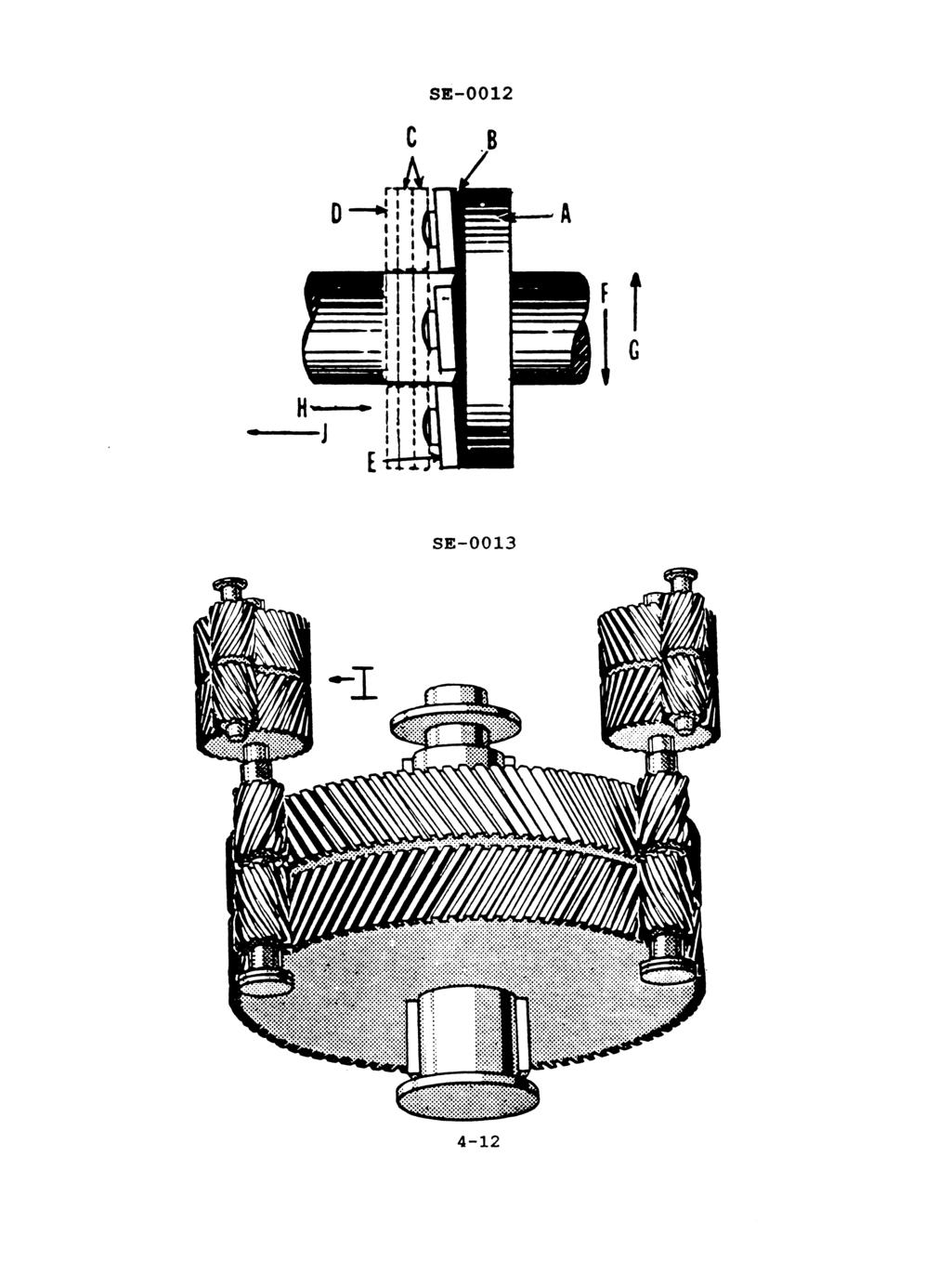
16 ABS VER 1 Illustration: SE-0012 (Marine Engineering, Harrington) The base ring shown in the illustration is identified by the letter. A. A Incorrect Answer: Item A is the thrust collar. B. C Incorrect Answer: Items C are the leveling plates. C. D Correct Answer: Item D is the base ring. D. E Incorrect Answer: Item E is the shoe.
17
18 ABS VER 3 Illustration: SE-0009 (Modern Marine Engineers Manual, Osbourne) In the illustration of a typical ship service turbogenerator control system, the device that monitors turbine exhaust pressure is labeled. A. K Incorrect Answer: The item labeled K is the main oil pump that is driven by the turbine shaft via a worm gear. B. J Correct Answer: Item J is the back pressure trip, which trips the turbine off the line in the event that the exhaust pressure gets too high. C. M Incorrect Answer: Item M is the main steam throttle valve through which steam is admitted to the turbine steam chest. D. F Incorrect Answer: Item F is the pilot valve which controls the flow of oil to the operating cylinder, O, which in turn controls the opening or closing of the turbine nozzle valves.
19
20 ABS VER 6 Illustration: SG-0024 (Marine Engineering, Harrington) Identify the system shown in the illustration. A. Bleed steam Correct Answer: Steady-state operation of the main propulsion turbines allows for a constant supply of steam to be extracted from bleed points within the turbines. Intermediate-pressure (IP) steam is extracted from the high-pressure turbine or from the crossover to the low-pressure turbine. IP bleed steam is typically used for the boiler air heaters and make-up steam for the auxiliary exhaust system. Low-pressure (LP) bleed steam is extracted from the low-pressure turbine, and is typically used for first stage feedwater heating and the distilling plant salt water feed heater. B. Auxiliary steam Incorrect Answer: The auxiliary steam system supplies steam from the boiler desuperheater directly or by way of reducing stations to all steam driven auxiliaries and ships services not served by the main steam (superheated) system. C. High pressure drains Incorrect Answer: High-pressure drains, which include low-point drains from the main and auxiliary desuperheated steam piping, are collected in a high pressure drain main and discharged to the deaerating feed tank (DFT). D. Auxiliary condensate Incorrect Answer: The auxiliary condensate system includes the equipment and piping utilized to collect the condensate from the auxiliary condenser and discharge to the DFT.
21
22 ABS VER 1 Illustration: RA-0005 (Machinist s Mate 3 & 2, NAVEDTRA) Which of the lettered components shown in the illustration indicates the high pressure cutout? A. E Incorrect Answer: Component E is the low pressure cutout. B. B Incorrect Answer: Component B is the liquid line solenoid valve. C. C Correct Answer: Component C is the high pressure cutout. D. F Incorrect Answer: Component F is the evaporator coil back pressure regulating valve.
23
24 ABS VER 1 Illustration: EL-0013 (46 CFR (d)) In the illustration, if BRANCH NO. 1 is a lighting circuit for crew s berthing, 46 CFR requires the maximum fuse rating for that branch to be. A. 15 amps Incorrect Answer: Choice C is the only correct answer. B. 80% of the connected load Incorrect Answer: Choice C is the only correct answer. C. 20 amps Correct Answer: 46 CFR (d) states Overcurrent protection. Each lighting branch circuit must be protected by an overcurrent device rated at 20 ampere or less, except as allowed under paragraph (e) of this section. D. 30 amps Incorrect Answer: Choice C is the only correct answer.
25
26 ABS VER 4 Illustration: GS-0077 (The Procedure Handbook of Electric Arc Welding) The weld type illustrated and indicated as 5B is known as a/an. A. X Incorrect Answer: An X weld type does not exist. B. K Incorrect Answer: A K weld type does not exist. C. double bevel Incorrect Answer: 3B is a double bevel groove weld type. D. double J Correct Answer: 5B is a double J groove weld type.
27
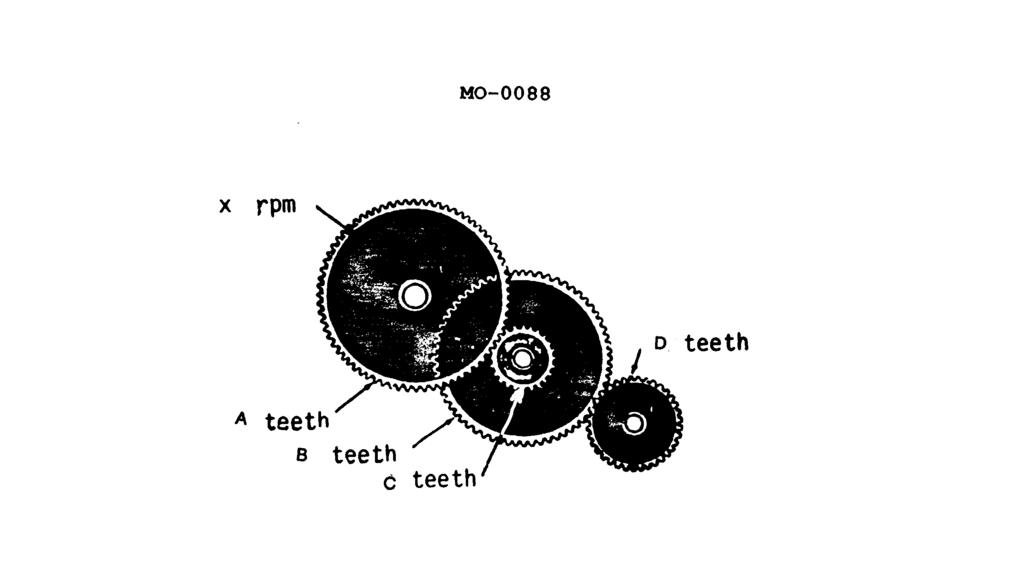
28 ABS VER 16 Illustration: MO-0088, (Basic Machines, NAVPERS) The RPM of gear D is 900 and is hobbed with 48 teeth. If gears A, B, and C have 88, 66, and 22 teeth respectively, the RPM of gear A in the gear train illustration is. A RPM Incorrect Answer: Choice B is the only correct answer. B RPM Correct Answer: The formula for any gear speed reduction problem is: S 2 = S 1 x (T1 T 2 ) S 2 = speed of last gear in train S 1 = speed of first gear in train T 1 = product of teeth on all drivers T 2 = product of teeth on all driven gears S 1 = 900 RPM T 1 = (48) (22) = 1056 T 2 = (66) (88) = 5808 S 2 = 900 ( ) = 900(.1818) = RPM C RPM Incorrect Answer: Choice B is the only correct answer. D RPM Incorrect Answer: Choice B is the only correct answer.
29
30 ABS VER 1 Illustration: MO-0113 From the graph shown in the illustration, if the separating temperature required is to be 167 F, and the specific gravity of the oil is.98 kg./dm3 at 59 F, what size regulating ring is required? A. 86 mm Incorrect Answer: Choice C is the only correct answer. B. 89 mm Incorrect Answer: Choice C is the only correct answer. C. 92 mm Correct Answer: For a given separating temperature, the inner diameter of the regulating ring can be determined from the diagram, provided that the specific gravity of the oil at a temperature ranging between 15 and 90 C is known. Given: Specific Gravity of 15 C (59 F) =.98 kg/dm 3 Separating temperature = 167 F = 75 C Plot of values on the graph indicate that a 92 mm inner diameter regulating ring is required (where solid arrows intersect on graph). D. 95 mm Incorrect Answer: Choice C is the only correct answer.
31
32
Engineering Fundamentals and Problem Solving, 6e
 Engineering Fundamentals and Problem Solving, 6e Chapter 17 Electrical Circuits Chapter Objectives Compute the equivalent resistance of resistors in series and in parallel Apply Ohm s law to a resistive
National 5 Physics. Electricity and Energy. Notes
 National 5 Physics Electricity and Energy Notes Name. 1 P a g e Key Area Notes, Examples and Questions Page 3 Conservation of energy Page 10 Electrical charge carriers and electric fields and potential
Lecture 3: Electrical Power and Energy
 Lecture 3: Electrical Power and Energy Recall from Lecture 2 E (V) I R E Voltage Similar to water pressure Unit: Volts (V) I Current Similar to water flow Unit: Amperes (A) R Resistance Similar to water
Chapter 33 - Electric Fields and Potential. Chapter 34 - Electric Current
 Chapter 33 - Electric Fields and Potential Chapter 34 - Electric Current Electric Force acts through a field An electric field surrounds every electric charge. It exerts a force that causes electric charges
PARTS LIST GAS BOILERS MODELS: CG320 (E) CG325 (E) CG330 (E)
 CG325 (E) CG330 (E)") PARTS LIST GAS BOILERS MODELS: CG320 (E) CG325 (E) CG330 (E) CROWN FOOD SERVICE EQUIPMENT LTD. 70 OAKDALE ROAD, DOWNSVIEW, (TORONTO), ONTARIO, CANADA, M3N 1V9 TELEPHONE: (416) 746-2358, FAX: (416) 746-8324
PARTS LIST GAS BOILERS MODELS: CG320 (E) CG325 (E) CG330 (E) CROWN FOOD SERVICE EQUIPMENT LTD. 70 OAKDALE ROAD, DOWNSVIEW, (TORONTO), ONTARIO, CANADA, M3N 1V9 TELEPHONE: (416) 746-2358, FAX: (416) 746-8324
Review. Multiple Choice Identify the letter of the choice that best completes the statement or answers the question.
 Review Multiple Choice Identify the letter of the choice that best completes the statement or answers the question. 1. When more devices are added to a series circuit, the total circuit resistance: a.
INTRODUCTION TO ISA SYMBOLOGY
 ERT 213/3 Process instrumentations INTRODUCTION TO ISA SYMBOLOGY DR. RAHIMAH BINTI OTHMAN (Email: rahimah@unimap.edu.my) COURSE OUTCOMES COs 3. Able to design process instruments in bioprocess engineering
US ARMY INTELLIGENCE CENTER CIRCUITS
 SUBCOURSE IT 0334 EDITION C US ARMY INTELLIGENCE CENTER CIRCUITS CIRCUITS Subcourse Number IT0334 EDITION C US ARMY INTELLIGENCE CENTER FORT HUACHUCA, AZ 85613-6000 4 Credit Hours Edition Date: December
Chapter 2. Engr228 Circuit Analysis. Dr Curtis Nelson
 Chapter 2 Engr228 Circuit Analysis Dr Curtis Nelson Chapter 2 Objectives Understand symbols and behavior of the following circuit elements: Independent voltage and current sources; Dependent voltage and
24 volts (0.25 amps current-limited)
") Question 1 Questions Suppose the lamp refuses to light up. A voltmeter registers 24 volts between test points C and D: A C E + 24 volts (0.25 amps current-limited) B D F First, list all the possible (single)
Question 1 Questions Suppose the lamp refuses to light up. A voltmeter registers 24 volts between test points C and D: A C E + 24 volts (0.25 amps current-limited) B D F First, list all the possible (single)
DC CIRCUIT ANALYSIS. Loop Equations
 All of the rules governing DC circuits that have been discussed so far can now be applied to analyze complex DC circuits. To apply these rules effectively, loop equations, node equations, and equivalent
Industrial Technology: Electronic Technology Crosswalk to AZ Math Standards
 Page 1 of 1 August 1998 1M-P1 Compare and contrast the real number system and its various subsystems with regard to their structural characteristics. PO 2 PO 3 2.0 Apply mathematics calculations. 2.1 Apply
SOME USEFUL NETWORK THEOREMS
 APPENDIX D SOME USEFUL NETWORK THEOREMS Introduction In this appendix we review three network theorems that are useful in simplifying the analysis of electronic circuits: Thévenin s theorem Norton s theorem
London Examinations IGCSE
 Centre No. Candidate No. Paper Reference(s) 4437/3F London Examinations IGCSE Science (Double Award) Physics Paper 3F Foundation Tier Wednesday 16 June 2010 Morning Time: 1 hour 15 minutes Materials required
VOLUMEC. Valve Position Indicator 5
 VOLUMEC Valve Position Indicator 5 2 KRACHT CORP. 8600 S Wilkinson Way Unit A Perrysburg, OH 43551 USA P +1 419 874 1000 F +1 419 874 1006 flowmeters@krachtcorp.com www.krachtcorp.com VOLUMEC Valve Position
2.0 KEY EQUATIONS. Evaporator Net Refrigeration Effect. Compressor Work. Net Condenser Effect
 2.0 KEY EQUATIONS Evaporator Net Refrigeration Effect Q net refrigeration effect [] = (H 1 H 4 ) lb (Refrig Flow Rate) (60) min lb min hr H 1 = leaving evaporator enthalpy lb ; H 4 = entering evaporator
DUBLIN INSTITUTE OF TECHNOLOGY Kevin Street, Dublin 8.
 Question Sheet Page 1 of 5 Instructions for the student: Question 1 is compulsory [40 marks] Attempt any two other questions [30 marks per question] The following must be made available during the examination:
16.1 Electrical Current
 16.1 Electrical Current Electric Current Electric Current When the ends of an electric conductor are at different electric potentials, charge flows from one end to the other Flow of Charge Charge flows
Physics 142 Steady Currents Page 1. Steady Currents
 Physics 142 Steady Currents Page 1 Steady Currents If at first you don t succeed, try, try again. Then quit. No sense being a damn fool about it. W.C. Fields Electric current: the slow average drift of
MODEL: WB009GMFI19HLD (120V) Wall Mount DC Inverter Fan Coil Unit 9,000 BTUH
 Wall Mount DC Inverter Fan Coil Unit 9,000 BTUH") MODEL: WB009GMFI19HLD (120V) Wall Mount DC Inverter Fan Coil Unit 9,000 BTUH No. Part Name Quantity BOM code List Price Remark 1 Panel assembly 1 201132890609 2 Air filter 2 201132890704 5 Display box
MODEL: WB009GMFI19HLD (120V) Wall Mount DC Inverter Fan Coil Unit 9,000 BTUH No. Part Name Quantity BOM code List Price Remark 1 Panel assembly 1 201132890609 2 Air filter 2 201132890704 5 Display box
Ratio of Charge to Mass (e/m) for the Electron
 for the Electron") Objective: In this experiment you will determine the ratio of charge to mass (e/m) of the electron, by measuring the deflecting of electrons as they move through a magnetic field. Apparatus: e/m apparatus
Objective: In this experiment you will determine the ratio of charge to mass (e/m) of the electron, by measuring the deflecting of electrons as they move through a magnetic field. Apparatus: e/m apparatus
PhysicsAndMathsTutor.com
 Electricity May 02 1. The graphs show the variation with potential difference V of the current I for three circuit elements. PhysicsAndMathsTutor.com When the four lamps are connected as shown in diagram
MEP 382: Design of Applied Measurement Systems Lecture 3: DC & AC Circuit Analysis
 Faculty of Engineering MEP 38: Design of Applied Measurement Systems Lecture 3: DC & AC Circuit Analysis Outline oltage and Current Ohm s Law Kirchoff s laws esistors Series and Parallel oltage Dividers
NPP Simulators for Education Workshop - Passive PWR Models
 NPP Simulators for Education Workshop - Passive PWR Models Wilson Lam (wilson@cti-simulation.com) CTI Simulation International Corp. www.cti-simulation.com Sponsored by IAEA Learning Objectives Understand
Electric Currents. Resistors (Chapters 27-28)
") Electric Currents. Resistors (Chapters 27-28) Electric current I Resistance R and resistors Relation between current and resistance: Ohm s Law Resistivity ρ Energy dissipated by current. Electric power
Electric Currents. Resistors (Chapters 27-28) Electric current I Resistance R and resistors Relation between current and resistance: Ohm s Law Resistivity ρ Energy dissipated by current. Electric power
1 Written and composed by: Prof. Muhammad Ali Malik (M. Phil. Physics), Govt. Degree College, Naushera
, Govt. Degree College, Naushera") CURRENT ELECTRICITY Q # 1. What do you know about electric current? Ans. Electric Current The amount of electric charge that flows through a cross section of a conductor per unit time is known as electric
CURRENT ELECTRICITY Q # 1. What do you know about electric current? Ans. Electric Current The amount of electric charge that flows through a cross section of a conductor per unit time is known as electric
Paper Reference(s) 5PH2H/01 Edexcel GCSE
 5PH2H/01 Edexcel GCSE") Paper Reference(s) 5PH2H/01 Edexcel GCSE Physics/Additional Science Unit 2: Physics for Your Future Higher Tier Thursday 24 May 2012 Morning Time: 1 hour plus your additional time allowance INSTRUCTIONS
Paper Reference(s) 5PH2H/01 Edexcel GCSE Physics/Additional Science Unit 2: Physics for Your Future Higher Tier Thursday 24 May 2012 Morning Time: 1 hour plus your additional time allowance INSTRUCTIONS
Electrical Engineering Fundamentals for Non-Electrical Engineers
 Electrical Engineering Fundamentals for Non-Electrical Engineers by Brad Meyer, PE Contents Introduction... 3 Definitions... 3 Power Sources... 4 Series vs. Parallel... 9 Current Behavior at a Node...
SCHOOL OF COMPUTING, ENGINEERING AND MATHEMATICS SEMESTER 1 EXAMINATIONS 2012/2013 XE121. ENGINEERING CONCEPTS (Test)
") s SCHOOL OF COMPUTING, ENGINEERING AND MATHEMATICS SEMESTER EXAMINATIONS 202/203 XE2 ENGINEERING CONCEPTS (Test) Time allowed: TWO hours Answer: Attempt FOUR questions only, a maximum of TWO questions
s SCHOOL OF COMPUTING, ENGINEERING AND MATHEMATICS SEMESTER EXAMINATIONS 202/203 XE2 ENGINEERING CONCEPTS (Test) Time allowed: TWO hours Answer: Attempt FOUR questions only, a maximum of TWO questions
Western Electric A V a c u u m T u b e
 280A Western Electric 2 8 0 A V a c u u m T u b e Classification Half-wave, thermionic, mercury vapor rectifier The 280A vacuum tube is designed to supply direct current from an alternating-current supply.
Physics 1214 Chapter 19: Current, Resistance, and Direct-Current Circuits
 Physics 1214 Chapter 19: Current, Resistance, and Direct-Current Circuits 1 Current current: (also called electric current) is an motion of charge from one region of a conductor to another. Current When
Gates and Flip-Flops
 Gates and Flip-Flops Chris Kervick (11355511) With Evan Sheridan and Tom Power December 2012 On a scale of 1 to 10, how likely is it that this question is using binary?...4? What s a 4? Abstract The operation
1. What would be the value of F1 to balance the system if F2=20N? 20cm T =? 20kg
 1. What would be the value of F1 to balance the system if F2=20N? F2 5cm 20cm F1 3 N 5 N 4N None of the above 2. The stress in a wire of diameter 2 mm, if a load of 100 gram is applied to the wire is 3.1
Electric Current & DC Circuits How to Use this File Electric Current & DC Circuits Click on the topic to go to that section Circuits
 Slide 1 / 127 Slide 2 / 127 Electric Current & DC Circuits www.njctl.org Slide 3 / 127 How to Use this File Slide 4 / 127 Electric Current & DC Circuits Each topic is composed of brief direct instruction
Electricity and Light Pre Lab Questions
 Electricity and Light Pre Lab Questions The pre lab questions can be answered by reading the theory and procedure for the related lab. You are strongly encouraged to answers these questions on your own.
TERM 1185 ONLINE APPRENTICESHIP CLASS NUMBERS
 Term Subject Area Catalog # Description Class Nbr Fee 1185 MPOA 1800 Basic Welding 1159 0.00 1185 ASTA 1804 Starting & Charging Systems 1007 0.00 1185 ASTA 1805 Ignition Systems 1008 0.00 1185 ASTA 1817
Chapter 7 Direct-Current Circuits
 Chapter 7 Direct-Current Circuits 7. Introduction... 7. Electromotive Force... 7.3 Resistors in Series and in Parallel... 4 7.4 Kirchhoff s Circuit Rules... 6 7.5 Voltage-Current Measurements... 8 7.6
A Review of Circuitry
 1 A Review of Circuitry There is an attractive force between a positive and a negative charge. In order to separate these charges, a force at least equal to the attractive force must be applied to one
Physics 115. General Physics II. Session 24 Circuits Series and parallel R Meters Kirchoff s Rules
 Physics 115 General Physics II Session 24 Circuits Series and parallel R Meters Kirchoff s Rules R. J. Wilkes Email: phy115a@u.washington.edu Home page: http://courses.washington.edu/phy115a/ 5/15/14 Phys
Panel Mount, Single Phase 120 and 240 Volt Fixed Shaft (click blue text for more details)
") Staco Energy Products Co. has been a leading manufacturer of variable transformers for over 60 years, building standard as well as custom-designed products for industrial, commercial and military applications.
Staco Energy Products Co. has been a leading manufacturer of variable transformers for over 60 years, building standard as well as custom-designed products for industrial, commercial and military applications.
Circuit Analysis and Ohm s Law
 Study Unit Circuit Analysis and Ohm s Law By Robert Cecci Circuit analysis is one of the fundamental jobs of an electrician or electronics technician With the knowledge of how voltage, current, and resistance
ELE2120 Digital Circuits and Systems. Tutorial Note 9
 ELE2120 Digital Circuits and Systems Tutorial Note 9 Outline 1. Exercise(1) Sequential Circuit Analysis 2. Exercise (2) Sequential Circuit Analysis 3. Exercise (3) Sequential Circuit Analysis 4. Ref. Construction
Simple circuits - 3 hr
 Simple circuits - 3 hr Resistances in circuits Analogy of water flow and electric current An electrical circuit consists of a closed loop with a number of different elements through which electric current
Digital Electronics. Delay Max. FF Rate Power/Gate High Low (ns) (MHz) (mw) (V) (V) Standard TTL (7400)
 (MHz) (mw) (V) (V) Standard TTL (7400)") P57/67 Lec9, P Digital Electronics Introduction: In electronics we can classify the building blocks of a circuit or system as being either analog or digital in nature. If we focus on voltage as the circuit
P57/67 Lec9, P Digital Electronics Introduction: In electronics we can classify the building blocks of a circuit or system as being either analog or digital in nature. If we focus on voltage as the circuit
EXPERIMENT 12 OHM S LAW
 EXPERIMENT 12 OHM S LAW INTRODUCTION: We will study electricity as a flow of electric charge, sometimes making analogies to the flow of water through a pipe. In order for electric charge to flow a complete
Physics 102 Spring 2006: Final Exam Multiple-Choice Questions
 Last Name: First Name: Physics 102 Spring 2006: Final Exam Multiple-Choice Questions For questions 1 and 2, refer to the graph below, depicting the potential on the x-axis as a function of x V x 60 40
II/IV B.Tech. DEGREE EXAMINATIONS, NOV/DEC-2017
 CSE/IT 213 (CR) Total No. of Questions :09] [Total No. of Pages : 03 II/IV B.Tech. DEGREE EXAMINATIONS, NOV/DEC-2017 First Semester CSE/IT BASIC ELECTRICAL AND ELECTRONICS ENGINEERING Time: Three Hours
Failures in Process Industries
 Fault Tree Analysis Failures in Process Industries Single Component Failure Data for failure rates are compiled by industry Single component or single action Multiple Component Failure Failures resulting
Summary Notes ALTERNATING CURRENT AND VOLTAGE
 HIGHER CIRCUIT THEORY Wheatstone Bridge Circuit Any method of measuring resistance using an ammeter or voltmeter necessarily involves some error unless the resistances of the meters themselves are taken
Increasing of the Stern Tube Bushes Precision by On-Line Adaptive Control of the Cutting Process
 Increasing of the Stern Tube Bushes Precision by On-Line Adaptive Control of the Cutting Process LUCIAN VASILIU, ALEXANDRU EPUREANU, GABRIEL FRUMUŞANU, VASILE MARINESCU Manufacturing Science and Engineering
math Pre and Post Exam Answer Key
 math Pre and Post Exam Answer Key Assembly ANSWERS AND EXPLANATIONS math 1. The correct answer is picture #2. Look at the ends marked A. If the ends marked A were put together, how would they look? Of
Chapter 28. Direct Current Circuits
 Chapter 28 Direct Current Circuits Circuit Analysis Simple electric circuits may contain batteries, resistors, and capacitors in various combinations. For some circuits, analysis may consist of combining
Edition 3 September Air Angle Wrench and Nut Runner. QA6 and QA8 Series. Parts Information. Save These Instructions
 660072 Edition 3 September 2007 Air Angle Wrench and Nut Runner QA6 and QA8 Series Parts Information Save These Instructions Module Exploded Diagram 7 5 9 7 2 9 50 3 8 3 38 39 8 9 20 2 33 22 23 3 2 3 37
Electric Charge. Conductors A material that transfers charge easily Metals
 Electric Charge An electrical property of matter that creates a force between objects. Like charges repel Opposite charges attract Equal amount of positive and negative = no net charge Electrons: Negative
EXEMPLAR NATIONAL CERTIFICATE (VOCATIONAL) ELECTRICAL PRINCIPLES AND PRACTICE NQF LEVEL 3 ( ) (X-Paper) 09:00 12:00
 ELECTRICAL PRINCIPLES AND PRACTICE NQF LEVEL 3 ( ) (X-Paper) 09:00 12:00") NATIONAL CERTIFICATE (VOCATIONAL) ELECTRICAL PRINCIPLES AND PRACTICE NQF LEVEL 3 2008 (12041002) (X-Paper) 09:00 12:00 EXEMPLAR This question paper consists of 7 pages. EXEMPLAR -2- NC(V) TIME: 3 HOURS
NATIONAL CERTIFICATE (VOCATIONAL) ELECTRICAL PRINCIPLES AND PRACTICE NQF LEVEL 3 2008 (12041002) (X-Paper) 09:00 12:00 EXEMPLAR This question paper consists of 7 pages. EXEMPLAR -2- NC(V) TIME: 3 HOURS
Continuing the Analogy. Electricity/Water Analogy: PHY205H1F Summer Physics of Everyday Life Class 8: Electric Current, Magnetism
 PHY205H1F ummer Physics of Everyday Life Class 8: Electric Current, Magnetism Flow of Charge Voltage, Current, Resistance Ohm s Law DC and AC Electric Power Light bulbs Electric Circuits Magnetic Force
Chapter 20 Electric Circuits
 Chapter 0 Electric Circuits Chevy olt --- Electric vehicle of the future Goals for Chapter 9 To understand the concept of current. To study resistance and Ohm s Law. To observe examples of electromotive
SECTION 1 - WHAT IS A BTU METER? BTU's = Flow x ΔT Any ISTEC BTU Meter System consists of the following main components:
 SECTION 1 - WHAT IS A BTU METER? ISTEC BTU Meters measure energy usage by multiplying flow rate and temperature difference. As the water (or other liquid) passes through these lines, the multi-wing turbine
CVE 372 HYDROMECHANICS EXERCISE PROBLEMS
 VE 37 HYDROMEHNIS EXERISE PROLEMS 1. pump that has the characteristic curve shown in the accompanying graph is to be installed in the system shown. What will be the discharge of water in the system? Take
UNIT II CURRENT ELECTRICITY
 UNIT II CUENT ELECTICITY Weightage : 07 Marks Electric current; flow of electric charges in a metllic conductor, drift velocity, mobility and their relation with electric current. Ohm s law electrical
Delta & Y Configurations, Principles of Superposition, Resistor Voltage Divider Designs
 BME/ISE 3511 Bioelectronics - Test Three Course Notes Fall 2016 Delta & Y Configurations, Principles of Superposition, esistor Voltage Divider Designs Use following techniques to solve for current through
Solenoid valve Types EVR 2 - EVR 40
 Data sheet Solenoid valve s EVR 2 - EVR 40 EVR is a direct or servo operated solenoid valve for liquid, suction, and hot gas lines with HCFC and HFC refrigerants. EVR valves are supplied complete or as
MECHANICAL ENGINEERING
 MECHANICAL ENGINEERING Paper I Time Allowed: Three Hours Maximum Marks: 200 INSTRUCTIONS Please read each of the following instructions carefully before attempting questions. Candidates should attempt
Gr. 11 Physics Electricity
 Gr. 11 Physics Electricity This chart contains a complete list of the lessons and homework for Gr. 11 Physics. Please complete all the worksheets and problems listed under Homework before the next class.
Applied Thermodynamics for Marine Systems Prof. P. K. Das Department of Mechanical Engineering Indian Institute of Technology, Kharagpur
 Applied Thermodynamics for Marine Systems Prof. P. K. Das Department of Mechanical Engineering Indian Institute of Technology, Kharagpur Lecture No - 03 First Law of Thermodynamics (Open System) Good afternoon,
Basic Electrical Engineering SYLLABUS. Total No. of Lecture Hrs. : 50 Exam Marks : 80
 SYLLABUS Subject Code: /25 No. of Lecture Hrs./ Week : 04 IA Marks : 20 Exam Hours : 03 Total No. of Lecture Hrs. : 50 Exam Marks : 80 Course objectives: Impart a basic knowledge of electrical quantities
U1 is zero based because its noninverting terminal is connected to circuit common. Therefore, the circuit reference voltage is 0 V.
 When you have completed this exercise, you will be able to operate a zener-clamped op amp comparator circuit using dc and ac voltages. You will verify your results with an oscilloscope. U1 is zero based
Circuits. Electric Current & DC Circuits. Slide 1 / 127. Slide 2 / 127. Slide 3 / 127. Slide 4 / 127. Slide 5 / 127. Slide 6 / 127
 Slide 1 / 127 Slide 2 / 127 New Jersey Center for Teaching and Learning Electric Current & DC Circuits www.njctl.org Progressive Science Initiative This material is made freely available at www.njctl.org
Electric Current & DC Circuits
 Electric Current & DC Circuits Circuits Click on the topic to go to that section Conductors Resistivity and Resistance Circuit Diagrams Measurement EMF & Terminal Voltage Kirchhoff's Rules Capacitors*
Chapter 19 Lecture Notes
 Chapter 19 Lecture Notes Physics 2424 - Strauss Formulas: R S = R 1 + R 2 +... C P = C 1 + C 2 +... 1/R P = 1/R 1 + 1/R 2 +... 1/C S = 1/C 1 + 1/C 2 +... q = q 0 [1-e -t/(rc) ] q = q 0 e -t/(rc τ = RC
Department of Mechanical Engineering
 UNDERGRADUATE COURSE DESCRIPTIONS 15102 Statics 3 Cr. Basic concepts. Forces, moments, and couples. Equilibrium of particles and rigid bodies. First and second moments. Structures (trusses, frames, machines).
Capacitance. A different kind of capacitor: Work must be done to charge a capacitor. Capacitors in circuits. Capacitor connected to a battery
 Capacitance The ratio C = Q/V is a conductor s self capacitance Units of capacitance: Coulomb/Volt = Farad A capacitor is made of two conductors with equal but opposite charge Capacitance depends on shape
Useful Formulas and Calculations
 Drive Design Speed Ratio = rpm (faster) = PD = N rpm (slower) pd n Where: rpm = Revolutions per minute PD = Larger pitch diameter pd = Smaller pitch diameter N = Larger sprocket grooves n = Smaller sprocket
September 2013 IENGINEERS- CONSULTANTS LECTURE NOTES SERIES ELECTRONICS ENGINEERING 1 YEAR UPTU. Circuit Analysis
 Circuit Analysis Voltage, Current and Resistance Relationship between Voltage, Current Resistance All materials are made up from atoms, and all atoms consist of protons, neutrons and electrons. Protons,
Kirchhoff's Laws and Circuit Analysis (EC 2)
") Kirchhoff's Laws and Circuit Analysis (EC ) Circuit analysis: solving for I and V at each element Linear circuits: involve resistors, capacitors, inductors Initial analysis uses only resistors Power sources,
Kirchhoff's Laws and Circuit Analysis (EC ) Circuit analysis: solving for I and V at each element Linear circuits: involve resistors, capacitors, inductors Initial analysis uses only resistors Power sources,
 Page 1 of 15 Page 2 of 15 Ohm s Law Basic Electricity Worksheet Topics Question 1 For a given amount of water pressure, which will flow a greater rate of water: a small (restrictive) nozzle or a large
Look over Chapter 26 sections 1-7 Examples 3, 7. Look over Chapter 18 sections 1-5, 8 over examples 1, 2, 5, 8, 9,
 Look over Chapter 26 sections 1-7 Examples 3, 7 Look over Chapter 18 sections 1-5, 8 over examples 1, 2, 5, 8, 9, 1)How to find a current in a wire. 2)What the Current Density and Draft Speed are. 3)What
Chapter 19. Electric Current, Resistance, and DC Circuit Analysis
 Chapter 19 Electric Current, Resistance, and DC Circuit Analysis I = dq/dt Current is charge per time SI Units: Coulombs/Second = Amps Direction of Electron Flow _ + Direction of Conventional Current:
What colour is the insulation around the wire connected to the live pin inside the plug? ... (1) (1)
 (1)") Q. Diagram shows a hairdryer. Diagram 2 shows how the heaters and fan of the hairdryer are connected to a 3-pin plug. The hairdryer does not have an earth wire. (a) What colour is the insulation around
Q. Diagram shows a hairdryer. Diagram 2 shows how the heaters and fan of the hairdryer are connected to a 3-pin plug. The hairdryer does not have an earth wire. (a) What colour is the insulation around
Objectives 106 CHAPTER 2 WORK
 Objectives Explain the relationship between work done in electrical systems, charge moved, and the potential difference. Calculate the amount of electrical charge in coulombs moving past a point in a circuit.
74LS393 Dual 4-Bit Binary Counter
 74LS393 Dual 4-Bit Binary Counter General Description Each of these monolithic circuits contains eight masterslave flip-flops and additional gating to implement two individual four-bit counters in a single
This addendum describes the use of new termination actions in the Arbitrary Control Experiment in FuelCell Version 3.8d and later.
 FuelCell Addendum Arbitrary Control Termination D. Johnson, Scribner Associates, Inc. 4/16/2007, Ver. 2 Introduction This addendum describes the use of new termination actions in the Arbitrary Control
Direct-Current Circuits
 Direct-Current Circuits A'.3/.". 39 '- )232.-/ 32,+/" 7+3(5-.)232.-/ 7 3244)'03,.5B )*+,"- &'&./( 0-1*234 35-2567+- *7 2829*4-& )"< 35- )*+,"-= 9-4-- 3563 A0.5.C2/'-231).D')232.')2-1 < /633-">&@5-:836+-0"1464-625"-4*43"
DC Circuit Analysis + 1 R 3 = 1 R R 2
 DC Circuit Analysis In analyzing circuits, it is generally the current that is of interest. You have seen how Ohm s Law can be used to analyze very simple circuits consisting of an EMF and single resistance.
PHYS 1444 Section 02 Review #2
 PHYS 1444 Section 02 Review #2 November 9, 2011 Ian Howley 1 1444 Test 2 Eq. Sheet Terminal voltage Resistors in series Resistors in parallel Magnetic field from long straight wire Ampére s Law Force on
Basic Electricity Video Exam
 Name: Class: Date: Basic Electricity Video Exam Multiple Choice Identify the choice that best completes the statement or answers the question. 1. Matter is made of. a. plasma, gas, and solid b. solid,
Unit 2 Electrical Quantities and Ohm s Law
 Electrical Quantities and Ohm s Law Objectives: Define a coulomb. Define an ampere. Define a volt. Define an ohm. Define a watt. Objectives: Compute electrical values using Ohm s law. Discuss basic types
first law of ThermodyNamics
 first law of ThermodyNamics First law of thermodynamics - Principle of conservation of energy - Energy can be neither created nor destroyed Basic statement When any closed system is taken through a cycle,
THREE-PHASE CIRCUITS
 THR-HAS CIRCUITS 4.1 Introduction Generation, Transmission and distribution of electricity via the National Grid system is accomplished by three-phase alternating currents. The voltage induced by a single
ø6, ø10, ø15, ø20, ø25, ø32, ø40, ø50, ø63 How to Order Switch rail Nil Standard stroke Refer to page 12 for standard stroke.
 Magnetically Coupled Rodless Cylinder: Direct Mount ype Series ø, ø, ø, ø, ø, ø, ø, ø0, ø Direct mount type mm mm mm mm mm mm mm 0 0 mm mm 00 MB Piping type Both sides piping type Centralized piping type
Electric charges. Basics of Electricity
 Electric charges Basics of Electricity Electron has a negative charge Neutron has a no charge Proton has a positive charge But what is a charge? Electric charge, like mass, is a fundamental property of
mith College Computer Science CSC270 Spring 16 Circuits and Systems Lecture Notes Week 3 Dominique Thiébaut
 mith College Computer Science CSC270 Spring 16 Circuits and Systems Lecture Notes Week 3 Dominique Thiébaut dthiebaut@smith.edu Crash Course in Electricity and Electronics Zero Physics background expected!
They keep the voltage the same and use this circuit to measure the current. Variable resistor. Reading on ammeter in amps
 1 Ksenia and Eva investigate five different variable resistors. They set each variable resistor to the maximum resistance. They keep the voltage the same and use this circuit to measure the current. A
UNIVERSITY OF CAMBRIDGE INTERNATIONAL EXAMINATIONS International General Certificate of Secondary Education
 UNIVERSITY OF CAMBRIDGE INTERNATIONAL EXAMINATIONS International General Certificate of Secondary Education *1264537134* PHYSICS 0625/21 Paper 2 Core October/November 2011 1 hour 15 minutes Candidates
ECE 1311: Electric Circuits. Chapter 2: Basic laws
 ECE 1311: Electric Circuits Chapter 2: Basic laws Basic Law Overview Ideal sources series and parallel Ohm s law Definitions open circuits, short circuits, conductance, nodes, branches, loops Kirchhoff's
Digital Electronics. Part A
 Digital Electronics Final Examination Part A Winter 2004-05 Student Name: Date: lass Period: Total Points: Multiple hoice Directions: Select the letter of the response which best completes the item or
Magnets attract some metals but not others
 Electricity and Magnetism Junior Science Magnets attract some metals but not others Some objects attract iron and steel. They are called magnets. Magnetic materials have the ability to attract some materials
SPH3U1 Lesson 01 Electricity
 ELECTRIC CURRENT AND POTENTIAL DIFFERENCE LEARNING GOALS Students will: Define what is meant by electric current. Solve problems involving current, charge and time. Know the difference between electron
CHAPTER 5 MASS AND ENERGY ANALYSIS OF CONTROL VOLUMES
 Thermodynamics: An Engineering Approach 8th Edition in SI Units Yunus A. Çengel, Michael A. Boles McGraw-Hill, 2015 CHAPTER 5 MASS AND ENERGY ANALYSIS OF CONTROL VOLUMES Lecture slides by Dr. Fawzi Elfghi
Chapter 2. Review of Digital Systems Design
 x 2-4 = 42.625. Chapter 2 Review of Digital Systems Design Numbering Systems Decimal number may be expressed as powers of 10. For example, consider a six digit decimal number 987654, which can be represented