LECTURE 4 Stresses in Elastic Solid. 1 Concept of Stress
|
|
|
- Loreen Knight
- 5 years ago
- Views:
Transcription
1 V. DEMENKO MECHANICS OF MATERIALS LECTURE 4 Stresses in Elastic Solid 1 Concept of Stress In order to characterize the law of internal forces distribution over the section a measure of their intensity should be introduced. The measure used is stress. Fig. 1 Consider an arbitrary cross-section A of elastic body (Fig. 1). We isolate an element of area average stress on the area We reduce the area A enclosing a point the internal force P[N] is acting on. The 2 A[m ] is taken to be ur p av ur P =. (1) A A by contracting it to the point K. Since the medium is continuous, a limiting process is applied as A 0. In the limit we obtain The vector quantity of true stress p r distribution at the point K within section A. r r r P dp p = lim =. (2) A 0 A da represents the intensity of internal forces Stress has the dimension of force divided by area. The SI unit of stress is Pascal: N Pa = or megapascal: 2 m 6 MPa = 10 Pa.
.")
2 2 V. DEMENKO MECHANICS OF MATERIALS 2015 Fig. 2 The stress in given point of a section considered as a vector quantity, i.e. it is characterized by magnitude and direction. Let us resolve the total stress vector into two components: one, directed along the normal to the section and the other one, lying in the section plane (see Fig. 2). Stress component directed along the normal to the section is called normal stress and designated with greek letter σ. The component lying in the section plane will be called the tangential (shearing) stress and designated with greek letter τ. 2 Relations Between Stresses and Internal Forces Fig. 3 In majority of cases, it is convenient to resolve the total stress into three components directed parallel to coordinate aes. For the point in the cross section of a bar it is shown in Fig. 3. For these components, the following rule of subscripts has been adopted: the first subscript corresponds the coordinate ais perpendicular to the plane; the second subscript gives the coordinate ais to which the given stress is parallel. According to this rule, normal stresses should be written with two subscripts, i.e. σ, but usually one of two subscripts is omitted.
3 V. DEMENKO MECHANICS OF MATERIALS Let us establish how the stresses and internal force factors in a bar cross section are interrelated. Multiplying the stresses elementary internal forces: σ, τ z and τ y by the area da, we obtain dn dq dq y z = σ = τ = τ y z da, da, da. (3) Summing these elementary forces over the area of the section we find epressions for main vector components of internal forces: N Q Q y z = = = A A A σ τ τ y z da, da, da. (4) Multiplying each of the elementary forces by the distance to the corresponding ais, we obtain the elementary moments of internal forces: ( τ ) ( τ ) dm = zda y+ yda z, dmy = ( σda) z, dmz = ( σda) y. Summing the elementary moments over the entire area of the section, we get the epressions for main moment components of internal forces: (5) A ( τ τ ), M = yz z y da My Mz = σzda, A = σyda. A (6) These formulas will be used in the further discussion for solving one of the principal problems in the theory of strength of materials: the determination of stresses with known internal force factors.


4 4 V. DEMENKO MECHANICS OF MATERIALS Saint-Venant's Principle The features of eternal forces application are manifested, as a rule, at distances not eceeding the characteristic dimensions of bar cross section (see Fig. 4). Fig. 4 Therefore one should neglect the portion of the bar located in the zone of eternal forces application if you will estimate internal stresses in the bar using the methods of mechanics of materials. Eample of Saint-Venant s principle is illustrated by Fig. 5, where vicinity of P-force application is the Saint-Venant s zone with nonuniform stress distribution. Fig. 5

 of internal force factor distribution along the length of bar is called diagram.")
5 V. DEMENKO MECHANICS OF MATERIALS Principle of Superposition Since deformations the mechanics of materials deals with, are relatively small (elastic), eternal forces may be assumed to act independently from one another, i.e. the deformations and internal forces appearing in elastic bodies do not depend on the order the eternal forces are applied in. Besides, the total effect of the whole system of forces acting on a body is assumed to be the sum of effects produced by each force separately. This is the principle of superposition. 5 Construction of Internal Force Factors Diagrams A graph (plot) of internal force factor distribution along the length of bar is called diagram. There are some rules of significant importance for diagrams constructing: 1. Diagrams of internal force factors are always constructed on aial line which is parallel to aial line of a bar. 2. The force factor magnitude is laid off along a normal to the ais. 3. The diagrams include denominations, dimensions, signs, numerical information. 6 Diagrams of Normal Forces In case only normal force occurs at cross sections of a rod we have tension or compression deformation. Bar in tension-compression will be named as a rod. Eamples of the rods and rod systems are shown in Fig. 6.


6 6 V. DEMENKO MECHANICS OF MATERIALS 2015


7 V. DEMENKO MECHANICS OF MATERIALS Fig. 6 Let us consider a bar of constant cross-sectional area (prismatic bar) with two oppositely directed forces applied to its ends: Fig. 7


8 8 V. DEMENKO MECHANICS OF MATERIALS 2015 Both in tension and compression, the bar is in equilibrium, i.e. the sum of all forces projections onto ais is equal to zero. The normal force N can be found by the method of sections: let the bar be virtually cut in the point where the force N is to be determined and the effect of rejected portion of a bar onto the remaining portion to be replaced by internal force N. In tension, the force Fig. 8 N is directed away from the section, having plus sign. In compression, it is directed to the section, having minus sign. the force Rule If the force N is directed away from the section then it has plus sign; if N is directed to the section, then it has minus sign. Generally, the value of normal force in any cross-section numerically equals to the algebraic sum of eternal forces applied to the part of a rod under consideration. Eample 1 Calculation of normal force in tensile rod Given: The bar of the total length l under the action of the force F. R.D: the normal force along the length of the bar. Consider the equilibrium of remaining portion: In our case, F = 0, F N = 0, N =+ F. N = F = const and graph is a straight line with abrupt changes in the points of forces F, R B Fig. 9 application, i.e. at the ends of the bar, by the magnitude of forces F = R. B
9 V. DEMENKO MECHANICS OF MATERIALS Eample 2 Calculation of normal force in compressed rod plane A B I F In this case, N = F = const and the graph is a straight line, but N < 0. N N F + F Eample 3 Calculation of normal forces in stepped prismatic bar Given: Bar of a stepped profile: F 1 = 60kN, F 2 = 40kN, F 3 = 70kN. R.D.: N ( ) Fig. 10 Fig. 11 The construction of normal forces diagram is to be started by division of bar into four portions I, II, III and IV according to the forces applied.
10 10 V. DEMENKO MECHANICS OF MATERIALS 2015 Herewith, we begin the normal forces diagram construction from free end of the bar. force If a number of forces are applied to a bar, the internal force factor, i.e. the normal N, can be found with the method of sections, using the conditions of equilibrium. In the section under consideration, the force algebraic sum of all forces acting on a bar up to the considered section: N is determined as the N k = F, i= 1 i where F i is an i-th force acting on the bar. If it turns out that N > 0, it will be directed away from section and be a tensile force; otherwise, it is directed to the section and is a compressive force: I ( ) = 1=+ 60kN, N II ( ) F1 60 N F IV III ( ) = = kn, N = F F = =+ kn, ( ) N = F F F = = kn. One should know the important rule in diagrams of normal forces constructing, since similar rules will be often used in further discussion. In points where an eternal force is applied, including support reactions, a diagram of normal forces shows a jump (abrupt) equal in magnitude to applied eternal force. In our eample, there are four forces (including the support reaction) and the diagram of normal forces has four jumps equal in magnitude to these forces, respectively. 7 Diagrams of Torsional Moments A bar subjected to torsion is called shaft. In shaft torsion, there appears a single internal force factor, torsional moment, or torque, which acts in the plane of shaft cross section. The eamples of torsion deformation are shown in Fig. 12


11 V. DEMENKO MECHANICS OF MATERIALS Fig
12 12 V. DEMENKO MECHANICS OF MATERIALS 2015 The internal torque appearing in section can be found from the condition of equilibrium for the right-hand or left-hand portion of the loaded shaft. Internal torsional moment in the cross-section, as earlier, will be equal to the algebraical sum of eternal moments applied to the part of the shaft under consideration (left or right). The rule of signs in torque diagram design: if, watching from the end of a shaft, eternal torsional moment rotates counterclockwise, corresponding component of the torque in cross-section of the shaft will be assumed to be negative and vice versa. A graph of internal torsional moments distribution along the length of a shaft is called the torque diagram. Eample 4 Calculation of internal torque moment of the shaft loaded by concentrated eternal moment M T M in the cross-section The condition of equilibrium for the righthand portion of the twisted shaft is M T = M = 0, whence M ( ) = M. T Fig. 13
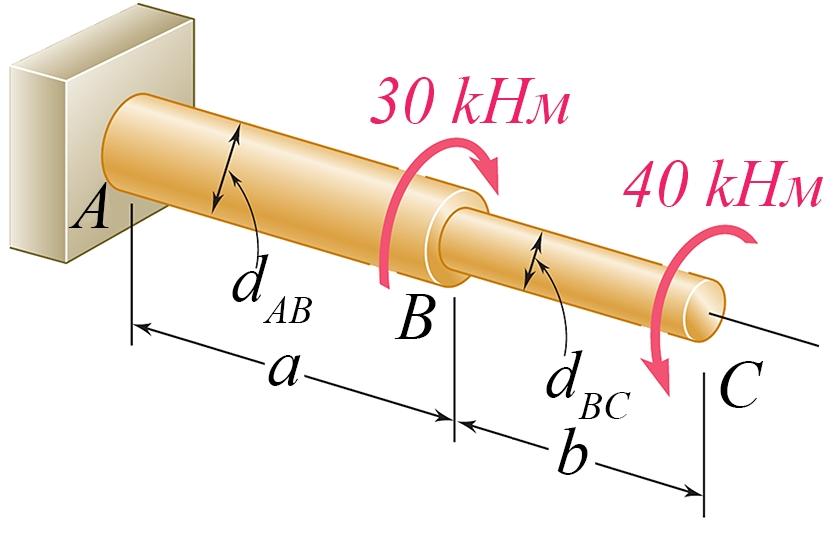
13 V. DEMENKO MECHANICS OF MATERIALS Eample 5 Construction of torque moment diagram for the shaft under an arbitrary loading Given: M 1 = 20kNm, M 2 = 50kNm, M 3 = 40kNm. R.D.: M( ) =? The internal torsional moment in a particular section of a shaft is equal to the algebraic sum of all eternal torsional moments which act on the shaft up to the Fig. 14 section considered: k = ( ), M I ( ) M1 20 M M F II i i= 1 = = knm, ( ) kNm 30 M = M M = = knm, III ( ) M = M M + M = + =+ knm. Let us now construct the diagram of torsional moments. For each portion of the shaft, we lay off M on a chosen scale in the same way as has been done for constructing the diagram of normal forces N in tension. A diagram of torsional moments has jumped in points of application of eternal torsional moments, which are equal to the magnitude of applied torsional moment. In the considered case, when moving leftwards along the shaft, we observe the first jump equal to M 1, the second jump equal to M 2, the third jump M 3 and the fourth jump is equal to the reaction moment in the built-in end of the shaft.
14 14 V. DEMENKO MECHANICS OF MATERIALS 2015 Glossary Normal stress (рус. нормальное напряжение, укр. нормальне напруження) the stress component at a point in a structure which is perpendicular to the reference plane. Tangential stress (рус. касательное напряжение, укр. дотичне напруження) A stress in which the material on one side of a surface pushes on the material on the other side of the surface with a force which is parallel to the surface. Also known as shear stress; tangential stress. Compression (рус. сжатие, укр. стиснення) Reduction in the volume of a substance due to pressure; for eample in building, the type of stress which causes shortening of the fibers of a wooden member.
- Beams are structural member supporting lateral loadings, i.e., these applied perpendicular to the axes.
 4. Shear and Moment functions - Beams are structural member supporting lateral loadings, i.e., these applied perpendicular to the aes. - The design of such members requires a detailed knowledge of the
MECE 3321 MECHANICS OF SOLIDS CHAPTER 1
 MECE 3321 MECHANICS O SOLIDS CHAPTER 1 Samantha Ramirez, MSE WHAT IS MECHANICS O MATERIALS? Rigid Bodies Statics Dynamics Mechanics Deformable Bodies Solids/Mech. Of Materials luids 1 WHAT IS MECHANICS
LECTURE 13 Strength of a Bar in Pure Bending
 V. DEMENKO MECHNCS OF MTERLS 015 1 LECTURE 13 Strength of a Bar in Pure Bending Bending is a tpe of loading under which bending moments and also shear forces occur at cross sections of a rod. f the bending
PDDC 1 st Semester Civil Engineering Department Assignments of Mechanics of Solids [ ] Introduction, Fundamentals of Statics
![PDDC 1 st Semester Civil Engineering Department Assignments of Mechanics of Solids [ ] Introduction, Fundamentals of Statics](/thumbs/92/109382806.jpg "PDDC 1 st Semester Civil Engineering Department Assignments of Mechanics of Solids [ ] Introduction, Fundamentals of Statics") Page1 PDDC 1 st Semester Civil Engineering Department Assignments of Mechanics of Solids [2910601] Introduction, Fundamentals of Statics 1. Differentiate between Scalar and Vector quantity. Write S.I.
Page1 PDDC 1 st Semester Civil Engineering Department Assignments of Mechanics of Solids [2910601] Introduction, Fundamentals of Statics 1. Differentiate between Scalar and Vector quantity. Write S.I.
6. Bending CHAPTER OBJECTIVES
 CHAPTER OBJECTIVES Determine stress in members caused by bending Discuss how to establish shear and moment diagrams for a beam or shaft Determine largest shear and moment in a member, and specify where
Stress Analysis Lecture 4 ME 276 Spring Dr./ Ahmed Mohamed Nagib Elmekawy
 Stress Analysis Lecture 4 ME 76 Spring 017-018 Dr./ Ahmed Mohamed Nagib Elmekawy Shear and Moment Diagrams Beam Sign Convention The positive directions are as follows: The internal shear force causes a
EMA 3702 Mechanics & Materials Science (Mechanics of Materials) Chapter 4 Pure Bending
 Chapter 4 Pure Bending") EA 3702 echanics & aterials Science (echanics of aterials) Chapter 4 Pure Bending Pure Bending Ch 2 Aial Loading & Parallel Loading: uniform normal stress and shearing stress distribution Ch 3 Torsion:
EA 3702 echanics & aterials Science (echanics of aterials) Chapter 4 Pure Bending Pure Bending Ch 2 Aial Loading & Parallel Loading: uniform normal stress and shearing stress distribution Ch 3 Torsion:
MECHANICS OF MATERIALS
 Fifth SI Edition CHTER 1 MECHNICS OF MTERILS Ferdinand. Beer E. Russell Johnston, Jr. John T. DeWolf David F. Mazurek Introduction Concept of Stress Lecture Notes: J. Walt Oler Teas Tech University Contents
A P P L I E D M E C H A N I C S I I 1. 1 I N T R O D U C T I O N
 A PPLIED MECHANICS II 1. 1 INTRODUCTION T h e second aspect of the course on A pplied Mechanics deals with the internal stress and strain g e n e r a t e d by eternally applied forces. 1. STRESS AND STRAIN
MECHANICS OF MATERIALS
 GE SI CHAPTER 3 MECHANICS OF MATERIALS Ferdinand P. Beer E. Russell Johnston, Jr. John T. DeWolf David F. Mazurek Torsion Lecture Notes: J. Walt Oler Texas Tech University Torsional Loads on Circular Shafts
CE 221: MECHANICS OF SOLIDS I CHAPTER 1: STRESS. Dr. Krisada Chaiyasarn Department of Civil Engineering, Faculty of Engineering Thammasat university
 CE 221: MECHANICS OF SOLIDS I CHAPTER 1: STRESS By Dr. Krisada Chaiyasarn Department of Civil Engineering, Faculty of Engineering Thammasat university Agenda Introduction to your lecturer Introduction
[8] Bending and Shear Loading of Beams
![[8] Bending and Shear Loading of Beams](/thumbs/92/110949676.jpg "[8] Bending and Shear Loading of Beams") [8] Bending and Shear Loading of Beams Page 1 of 28 [8] Bending and Shear Loading of Beams [8.1] Bending of Beams (will not be covered in class) [8.2] Bending Strain and Stress [8.3] Shear in Straight
[8] Bending and Shear Loading of Beams Page 1 of 28 [8] Bending and Shear Loading of Beams [8.1] Bending of Beams (will not be covered in class) [8.2] Bending Strain and Stress [8.3] Shear in Straight
7.4 The Elementary Beam Theory
 7.4 The Elementary Beam Theory In this section, problems involving long and slender beams are addressed. s with pressure vessels, the geometry of the beam, and the specific type of loading which will be
Mechanical Design in Optical Engineering
 Torsion Torsion: Torsion refers to the twisting of a structural member that is loaded by couples (torque) that produce rotation about the member s longitudinal axis. In other words, the member is loaded
Comb Resonator Design (2)
") Lecture 6: Comb Resonator Design () -Intro. to Mechanics of Materials Sh School of felectrical ti lengineering i and dcomputer Science, Si Seoul National University Nano/Micro Systems & Controls Laboratory
Lecture 6: Comb Resonator Design () -Intro. to Mechanics of Materials Sh School of felectrical ti lengineering i and dcomputer Science, Si Seoul National University Nano/Micro Systems & Controls Laboratory
Beams. Beams are structural members that offer resistance to bending due to applied load
 Beams Beams are structural members that offer resistance to bending due to applied load 1 Beams Long prismatic members Non-prismatic sections also possible Each cross-section dimension Length of member
Advanced Structural Analysis EGF Section Properties and Bending
 Advanced Structural Analysis EGF316 3. Section Properties and Bending 3.1 Loads in beams When we analyse beams, we need to consider various types of loads acting on them, for example, axial forces, shear
MECHANICS OF MATERIALS Design of a Transmission Shaft
 Design of a Transmission Shaft If power is transferred to and from the shaft by gears or sprocket wheels, the shaft is subjected to transverse loading as well as shear loading. Normal stresses due to transverse
FIXED BEAMS IN BENDING
 FIXED BEAMS IN BENDING INTRODUCTION Fixed or built-in beams are commonly used in building construction because they possess high rigidity in comparison to simply supported beams. When a simply supported
Consider an elastic spring as shown in the Fig.2.4. When the spring is slowly
 .3 Strain Energy Consider an elastic spring as shown in the Fig..4. When the spring is slowly pulled, it deflects by a small amount u 1. When the load is removed from the spring, it goes back to the original
Samantha Ramirez, MSE. Stress. The intensity of the internal force acting on a specific plane (area) passing through a point. F 2
 passing through a point. F 2") Samantha Ramirez, MSE Stress The intensity of the internal force acting on a specific plane (area) passing through a point. Δ ΔA Δ z Δ 1 2 ΔA Δ x Δ y ΔA is an infinitesimal size area with a uniform force
Samantha Ramirez, MSE Stress The intensity of the internal force acting on a specific plane (area) passing through a point. Δ ΔA Δ z Δ 1 2 ΔA Δ x Δ y ΔA is an infinitesimal size area with a uniform force
Section 6: PRISMATIC BEAMS. Beam Theory
 Beam Theory There are two types of beam theory aailable to craft beam element formulations from. They are Bernoulli-Euler beam theory Timoshenko beam theory One learns the details of Bernoulli-Euler beam
Fig Example 8-4. Rotor shaft of a helicopter (combined torsion and axial force).
.") PEF 309 Fundamentos de Mecânica das Estruturas Eercícios resolvidos etraídos de Mechanics of Materials, th edition, GERE, J.M. e Timoshenko, S.P.,PWS Publishing Company, 997, Boston, USA, p.08-0, 580-583.
PEF 309 Fundamentos de Mecânica das Estruturas Eercícios resolvidos etraídos de Mechanics of Materials, th edition, GERE, J.M. e Timoshenko, S.P.,PWS Publishing Company, 997, Boston, USA, p.08-0, 580-583.
(48) CHAPTER 3: TORSION
 CHAPTER 3: TORSION") (48) CHAPTER 3: TORSION Introduction: In this chapter structural members and machine parts that are in torsion will be considered. More specifically, you will analyze the stresses and strains in members
(48) CHAPTER 3: TORSION Introduction: In this chapter structural members and machine parts that are in torsion will be considered. More specifically, you will analyze the stresses and strains in members
Mechanics of Materials II. Chapter III. A review of the fundamental formulation of stress, strain, and deflection
 Mechanics of Materials II Chapter III A review of the fundamental formulation of stress, strain, and deflection Outline Introduction Assumtions and limitations Axial loading Torsion of circular shafts
MECHANICS OF MATERIALS. Prepared by Engr. John Paul Timola
 MECHANICS OF MATERIALS Prepared by Engr. John Paul Timola Mechanics of materials branch of mechanics that studies the internal effects of stress and strain in a solid body. stress is associated with the
MECHANICS OF MATERIALS. Analysis of Beams for Bending
 MECHANICS OF MATERIALS Analysis of Beams for Bending By NUR FARHAYU ARIFFIN Faculty of Civil Engineering & Earth Resources Chapter Description Expected Outcomes Define the elastic deformation of an axially
Stress and Strain ( , 3.14) MAE 316 Strength of Mechanical Components NC State University Department of Mechanical & Aerospace Engineering
 MAE 316 Strength of Mechanical Components NC State University Department of Mechanical & Aerospace Engineering") (3.8-3.1, 3.14) MAE 316 Strength of Mechanical Components NC State Universit Department of Mechanical & Aerospace Engineering 1 Introduction MAE 316 is a continuation of MAE 314 (solid mechanics) Review
(3.8-3.1, 3.14) MAE 316 Strength of Mechanical Components NC State Universit Department of Mechanical & Aerospace Engineering 1 Introduction MAE 316 is a continuation of MAE 314 (solid mechanics) Review
14. *14.8 CASTIGLIANO S THEOREM
 *14.8 CASTIGLIANO S THEOREM Consider a body of arbitrary shape subjected to a series of n forces P 1, P 2, P n. Since external work done by forces is equal to internal strain energy stored in body, by
Strength of Materials Prof S. K. Bhattacharya Department of Civil Engineering Indian Institute of Technology, Kharagpur Lecture - 18 Torsion - I
 Strength of Materials Prof S. K. Bhattacharya Department of Civil Engineering Indian Institute of Technology, Kharagpur Lecture - 18 Torsion - I Welcome to the first lesson of Module 4 which is on Torsion
Structural Analysis I Chapter 4 - Torsion TORSION
 ORSION orsional stress results from the action of torsional or twisting moments acting about the longitudinal axis of a shaft. he effect of the application of a torsional moment, combined with appropriate
CHAPTER -6- BENDING Part -1-
 Ishik University / Sulaimani Civil Engineering Department Mechanics of Materials CE 211 CHAPTER -6- BENDING Part -1-1 CHAPTER -6- Bending Outlines of this chapter: 6.1. Chapter Objectives 6.2. Shear and
Mechanics of Materials
 Mechanics of Materials 2. Introduction Dr. Rami Zakaria References: 1. Engineering Mechanics: Statics, R.C. Hibbeler, 12 th ed, Pearson 2. Mechanics of Materials: R.C. Hibbeler, 9 th ed, Pearson 3. Mechanics
Torsion of Shafts Learning objectives
 Torsion of Shafts Shafts are structural members with length significantly greater than the largest cross-sectional dimension used in transmitting torque from one plane to another. Learning objectives Understand
CHAPTER OBJECTIVES CHAPTER OUTLINE. 4. Axial Load
 CHAPTER OBJECTIVES Determine deformation of axially loaded members Develop a method to find support reactions when it cannot be determined from euilibrium euations Analyze the effects of thermal stress
M. Vable Mechanics of Materials: Chapter 5. Torsion of Shafts
 Torsion of Shafts Shafts are structural members with length significantly greater than the largest cross-sectional dimension used in transmitting torque from one plane to another. Learning objectives Understand
7 TRANSVERSE SHEAR transverse shear stress longitudinal shear stresses
 7 TRANSVERSE SHEAR Before we develop a relationship that describes the shear-stress distribution over the cross section of a beam, we will make some preliminary remarks regarding the way shear acts within
(Refer Slide Time: 01:00 01:01)
") Strength of Materials Prof: S.K.Bhattacharya Department of Civil Engineering Indian institute of Technology Kharagpur Lecture no 27 Lecture Title: Stresses in Beams- II Welcome to the second lesson of
Strength of Materials Prof: S.K.Bhattacharya Department of Civil Engineering Indian institute of Technology Kharagpur Lecture no 27 Lecture Title: Stresses in Beams- II Welcome to the second lesson of
CHAPTER 6: Shearing Stresses in Beams
 (130) CHAPTER 6: Shearing Stresses in Beams When a beam is in pure bending, the only stress resultants are the bending moments and the only stresses are the normal stresses acting on the cross sections.
3. BEAMS: STRAIN, STRESS, DEFLECTIONS
 3. BEAMS: STRAIN, STRESS, DEFLECTIONS The beam, or flexural member, is frequently encountered in structures and machines, and its elementary stress analysis constitutes one of the more interesting facets
CHAPTER 4: BENDING OF BEAMS
 (74) CHAPTER 4: BENDING OF BEAMS This chapter will be devoted to the analysis of prismatic members subjected to equal and opposite couples M and M' acting in the same longitudinal plane. Such members are
UNIT 1 STRESS STRAIN AND DEFORMATION OF SOLIDS, STATES OF STRESS 1. Define stress. When an external force acts on a body, it undergoes deformation.
 UNIT 1 STRESS STRAIN AND DEFORMATION OF SOLIDS, STATES OF STRESS 1. Define stress. When an external force acts on a body, it undergoes deformation. At the same time the body resists deformation. The magnitude
Chapter Objectives. Copyright 2011 Pearson Education South Asia Pte Ltd
 Chapter Objectives To determine the torsional deformation of a perfectly elastic circular shaft. To determine the support reactions when these reactions cannot be determined solely from the moment equilibrium
Stress Strain Elasticity Modulus Young s Modulus Shear Modulus Bulk Modulus. Case study
 Stress Strain Elasticity Modulus Young s Modulus Shear Modulus Bulk Modulus Case study 2 In field of Physics, it explains how an object deforms under an applied force Real rigid bodies are elastic we can
Chapter 5 CENTRIC TENSION OR COMPRESSION ( AXIAL LOADING )
") Chapter 5 CENTRIC TENSION OR COMPRESSION ( AXIAL LOADING ) 5.1 DEFINITION A construction member is subjected to centric (axial) tension or compression if in any cross section the single distinct stress
Chapter 5 CENTRIC TENSION OR COMPRESSION ( AXIAL LOADING ) 5.1 DEFINITION A construction member is subjected to centric (axial) tension or compression if in any cross section the single distinct stress
Solution: The strain in the bar is: ANS: E =6.37 GPa Poison s ration for the material is:
 Problem 10.4 A prismatic bar with length L 6m and a circular cross section with diameter D 0.0 m is subjected to 0-kN compressive forces at its ends. The length and diameter of the deformed bar are measured
ARC 341 Structural Analysis II. Lecture 10: MM1.3 MM1.13
 ARC241 Structural Analysis I Lecture 10: MM1.3 MM1.13 MM1.4) Analysis and Design MM1.5) Axial Loading; Normal Stress MM1.6) Shearing Stress MM1.7) Bearing Stress in Connections MM1.9) Method of Problem
Engineering Mechanics Department of Mechanical Engineering Dr. G. Saravana Kumar Indian Institute of Technology, Guwahati
 Engineering Mechanics Department of Mechanical Engineering Dr. G. Saravana Kumar Indian Institute of Technology, Guwahati Module 3 Lecture 6 Internal Forces Today, we will see analysis of structures part
3.5 STRESS AND STRAIN IN PURE SHEAR. The next element is in a state of pure shear.
 3.5 STRESS AND STRAIN IN PURE SHEAR The next element is in a state of pure shear. Fig. 3-20 Stresses acting on a stress element cut from a bar in torsion (pure shear) Stresses on inclined planes Fig. 3-21
Aircraft Structures Structural & Loading Discontinuities
 Universit of Liège Aerospace & Mechanical Engineering Aircraft Structures Structural & Loading Discontinuities Ludovic Noels Computational & Multiscale Mechanics of Materials CM3 http://www.ltas-cm3.ulg.ac.be/
Module 5: Theories of Failure
 Module 5: Theories of Failure Objectives: The objectives/outcomes of this lecture on Theories of Failure is to enable students for 1. Recognize loading on Structural Members/Machine elements and allowable
Stress Analysis Lecture 3 ME 276 Spring Dr./ Ahmed Mohamed Nagib Elmekawy
 Stress Analysis Lecture 3 ME 276 Spring 2017-2018 Dr./ Ahmed Mohamed Nagib Elmekawy Axial Stress 2 Beam under the action of two tensile forces 3 Beam under the action of two tensile forces 4 Shear Stress
Chapter 3. Load and Stress Analysis. Lecture Slides
 Lecture Slides Chapter 3 Load and Stress Analysis 2015 by McGraw Hill Education. This is proprietary material solely for authorized instructor use. Not authorized for sale or distribution in any manner.
Strength of Materials Prof. S.K.Bhattacharya Dept. of Civil Engineering, I.I.T., Kharagpur Lecture No.26 Stresses in Beams-I
 Strength of Materials Prof. S.K.Bhattacharya Dept. of Civil Engineering, I.I.T., Kharagpur Lecture No.26 Stresses in Beams-I Welcome to the first lesson of the 6th module which is on Stresses in Beams
MECHANICS OF MATERIALS
 2009 The McGraw-Hill Companies, Inc. All rights reserved. Fifth SI Edition CHAPTER 3 MECHANICS OF MATERIALS Ferdinand P. Beer E. Russell Johnston, Jr. John T. DeWolf David F. Mazurek Torsion Lecture Notes:
SN QUESTION YEAR MARK 1. State and prove the relationship between shearing stress and rate of change of bending moment at a section in a loaded beam.
 ALPHA COLLEGE OF ENGINEERING AND TECHNOLOGY DEPARTMENT OF MECHANICAL ENGINEERING MECHANICS OF SOLIDS (21000) ASSIGNMENT 1 SIMPLE STRESSES AND STRAINS SN QUESTION YEAR MARK 1 State and prove the relationship
KINGS COLLEGE OF ENGINEERING DEPARTMENT OF MECHANICAL ENGINEERING QUESTION BANK. Subject code/name: ME2254/STRENGTH OF MATERIALS Year/Sem:II / IV
 KINGS COLLEGE OF ENGINEERING DEPARTMENT OF MECHANICAL ENGINEERING QUESTION BANK Subject code/name: ME2254/STRENGTH OF MATERIALS Year/Sem:II / IV UNIT I STRESS, STRAIN DEFORMATION OF SOLIDS PART A (2 MARKS)
Strength of Materials (15CV 32)
") Strength of Materials (15CV 32) Module 1 : Simple Stresses and Strains Dr. H. Ananthan, Professor, VVIET,MYSURU 8/21/2017 Introduction, Definition and concept and of stress and strain. Hooke s law, Stress-Strain
Strength of Materials (15CV 32) Module 1 : Simple Stresses and Strains Dr. H. Ananthan, Professor, VVIET,MYSURU 8/21/2017 Introduction, Definition and concept and of stress and strain. Hooke s law, Stress-Strain
Tuesday, February 11, Chapter 3. Load and Stress Analysis. Dr. Mohammad Suliman Abuhaiba, PE
 1 Chapter 3 Load and Stress Analysis 2 Chapter Outline Equilibrium & Free-Body Diagrams Shear Force and Bending Moments in Beams Singularity Functions Stress Cartesian Stress Components Mohr s Circle for
NORMAL STRESS. The simplest form of stress is normal stress/direct stress, which is the stress perpendicular to the surface on which it acts.
 NORMAL STRESS The simplest form of stress is normal stress/direct stress, which is the stress perpendicular to the surface on which it acts. σ = force/area = P/A where σ = the normal stress P = the centric
Module 3 : Equilibrium of rods and plates Lecture 15 : Torsion of rods. The Lecture Contains: Torsion of Rods. Torsional Energy
 The Lecture Contains: Torsion of Rods Torsional Energy This lecture is adopted from the following book 1. Theory of Elasticity, 3 rd edition by Landau and Lifshitz. Course of Theoretical Physics, vol-7
OUTCOME 1 - TUTORIAL 3 BENDING MOMENTS. You should judge your progress by completing the self assessment exercises. CONTENTS
 Unit 2: Unit code: QCF Level: 4 Credit value: 15 Engineering Science L/601/1404 OUTCOME 1 - TUTORIAL 3 BENDING MOMENTS 1. Be able to determine the behavioural characteristics of elements of static engineering
MINISTRY OF EDUCATION AND SCIENCE OF UKRAINE. National aerospace university Kharkiv Aviation Institute. Department of aircraft strength
 MINISTRY OF EDUCATION AND SCIENCE OF UKRAINE National aerospace university Kharkiv Aviation Institute Department of aircraft strength Course Mechanics of materials and structures HOME PROBLEM 8 Strength
MINISTRY OF EDUCATION AND SCIENCE OF UKRAINE. National aerospace university Kharkiv Aviation Institute. Department of aircraft strength
 MNSTRY OF EDUCATON AND SCENCE OF UKRANE National aerospace universit Kharkiv Aviation nstitute Department of aircraft strength Course Mechanics of materials and structures HOME PROBLEM 9 Stress Analsis
Stresses in Curved Beam
 Stresses in Curved Beam Consider a curved beam subjected to bending moment M b as shown in the figure. The distribution of stress in curved flexural member is determined by using the following assumptions:
Elasticity and Plasticity. 1.Basic principles of Elasticity and plasticity. 2.Stress and Deformation of Bars in Axial load 1 / 59
 Elasticity and Plasticity 1.Basic principles of Elasticity and plasticity 2.Stress and Deformation of Bars in Axial load 1 / 59 Basic principles of Elasticity and plasticity Elasticity and plasticity in
VYSOKÁ ŠKOLA BÁŇSKÁ TECHNICKÁ UNIVERZITA OSTRAVA
 VYSOKÁ ŠKOLA BÁŇSKÁ TECHNICKÁ UNIVERZITA OSTRAVA FAKULTA METALURGIE A MATERIÁLOVÉHO INŽENÝRSTVÍ APPLIED MECHANICS Study Support Leo Václavek Ostrava 2015 Title:Applied Mechanics Code: Author: doc. Ing.
PES Institute of Technology
 PES Institute of Technology Bangalore south campus, Bangalore-5460100 Department of Mechanical Engineering Faculty name : Madhu M Date: 29/06/2012 SEM : 3 rd A SEC Subject : MECHANICS OF MATERIALS Subject
STRESS, STRAIN AND DEFORMATION OF SOLIDS
 VELAMMAL COLLEGE OF ENGINEERING AND TECHNOLOGY, MADURAI 625009 DEPARTMENT OF CIVIL ENGINEERING CE8301 STRENGTH OF MATERIALS I -------------------------------------------------------------------------------------------------------------------------------
Chapter 3. Inertia. Force. Free Body Diagram. Net Force. Mass. quantity of matter composing a body represented by m. units are kg
 Chapter 3 Mass quantity of matter composing a body represented by m Kinetic Concepts for Analyzing Human Motion units are kg Inertia tendency to resist change in state of motion proportional to mass has
MECHANICS OF MATERIALS
 Third E CHAPTER 1 Introduction MECHANICS OF MATERIALS Ferdinand P. Beer E. Russell Johnston, Jr. John T. DeWolf Lecture Notes: J. Walt Oler Texas Tech University Concept of Stress Contents Concept of Stress
Mechanics of Solids. Mechanics Of Solids. Suraj kr. Ray Department of Civil Engineering
 Mechanics Of Solids Suraj kr. Ray (surajjj2445@gmail.com) Department of Civil Engineering 1 Mechanics of Solids is a branch of applied mechanics that deals with the behaviour of solid bodies subjected
Combined Stresses and Mohr s Circle. General Case of Combined Stresses. General Case of Combined Stresses con t. Two-dimensional stress condition
 Combined Stresses and Mohr s Circle Material in this lecture was taken from chapter 4 of General Case of Combined Stresses Two-dimensional stress condition General Case of Combined Stresses con t The normal
Sub. Code:
 Important Instructions to examiners: ) The answers should be examined by key words and not as word-to-word as given in the model answer scheme. ) The model answer and the answer written by candidate may
PROBLEM #1.1 (4 + 4 points, no partial credit)
") PROBLEM #1.1 ( + points, no partial credit A thermal switch consists of a copper bar which under elevation of temperature closes a gap and closes an electrical circuit. The copper bar possesses a length
PROBLEM #1.1 ( + points, no partial credit A thermal switch consists of a copper bar which under elevation of temperature closes a gap and closes an electrical circuit. The copper bar possesses a length
The problem of transmitting a torque or rotary motion from one plane to another is frequently encountered in machine design.
 CHAPER ORSION ORSION orsion refers to the twisting of a structural member when it is loaded by moments/torques that produce rotation about the longitudinal axis of the member he problem of transmitting
STRESS STRAIN AND DEFORMATION OF SOLIDS, STATES OF STRESS
 1 UNIT I STRESS STRAIN AND DEFORMATION OF SOLIDS, STATES OF STRESS 1. Define: Stress When an external force acts on a body, it undergoes deformation. At the same time the body resists deformation. The
Comb resonator design (2)
") Lecture 6: Comb resonator design () -Intro Intro. to Mechanics of Materials School of Electrical l Engineering i and Computer Science, Seoul National University Nano/Micro Systems & Controls Laboratory
Lecture 6: Comb resonator design () -Intro Intro. to Mechanics of Materials School of Electrical l Engineering i and Computer Science, Seoul National University Nano/Micro Systems & Controls Laboratory
4.5 The framework element stiffness matrix
 45 The framework element stiffness matri Consider a 1 degree-of-freedom element that is straight prismatic and symmetric about both principal cross-sectional aes For such a section the shear center coincides
Unit I Stress and Strain
 Unit I Stress and Strain Stress and strain at a point Tension, Compression, Shear Stress Hooke s Law Relationship among elastic constants Stress Strain Diagram for Mild Steel, TOR steel, Concrete Ultimate
2/28/2006 Statics ( F.Robilliard) 1
 1") 2/28/2006 Statics (.Robilliard) 1 Extended Bodies: In our discussion so far, we have considered essentially only point masses, under the action of forces. We now broaden our considerations to extended
2/28/2006 Statics (.Robilliard) 1 Extended Bodies: In our discussion so far, we have considered essentially only point masses, under the action of forces. We now broaden our considerations to extended
Chapter 12. Static Equilibrium and Elasticity
 Chapter 12 Static Equilibrium and Elasticity Static Equilibrium Equilibrium implies that the object moves with both constant velocity and constant angular velocity relative to an observer in an inertial
REVIEW FOR EXAM II. Dr. Ibrahim A. Assakkaf SPRING 2002
 REVIEW FOR EXM II. J. Clark School of Engineering Department of Civil and Environmental Engineering b Dr. Ibrahim. ssakkaf SPRING 00 ENES 0 Mechanics of Materials Department of Civil and Environmental
Torsion of shafts with circular symmetry
 orsion of shafts with circular symmetry Introduction Consider a uniform bar which is subject to a torque, eg through the action of two forces F separated by distance d, hence Fd orsion is the resultant
Members Subjected to Combined Loads
 Members Subjected to Combined Loads Combined Bending & Twisting : In some applications the shaft are simultaneously subjected to bending moment M and Torque T.The Bending moment comes on the shaft due
ME325 EXAM I (Sample)
") ME35 EXAM I (Sample) NAME: NOTE: COSED BOOK, COSED NOTES. ONY A SINGE 8.5x" ORMUA SHEET IS AOWED. ADDITIONA INORMATION IS AVAIABE ON THE AST PAGE O THIS EXAM. DO YOUR WORK ON THE EXAM ONY (NO SCRATCH PAPER
ME35 EXAM I (Sample) NAME: NOTE: COSED BOOK, COSED NOTES. ONY A SINGE 8.5x" ORMUA SHEET IS AOWED. ADDITIONA INORMATION IS AVAIABE ON THE AST PAGE O THIS EXAM. DO YOUR WORK ON THE EXAM ONY (NO SCRATCH PAPER
Determine the resultant internal loadings acting on the cross section at C of the beam shown in Fig. 1 4a.
 E X M P L E 1.1 Determine the resultant internal loadings acting on the cross section at of the beam shown in Fig. 1 a. 70 N/m m 6 m Fig. 1 Support Reactions. This problem can be solved in the most direct
Members Subjected to Torsional Loads
 Members Subjected to Torsional Loads Torsion of circular shafts Definition of Torsion: Consider a shaft rigidly clamped at one end and twisted at the other end by a torque T = F.d applied in a plane perpendicular
Strength of Materials II (Mechanics of Materials) (SI Units) Dr. Ashraf Alfeehan
 (SI Units) Dr. Ashraf Alfeehan") Strength of Materials II (Mechanics of Materials) (SI Units) Dr. Ashraf Alfeehan 2017-2018 Mechanics of Material II Text Books Mechanics of Materials, 10th edition (SI version), by: R. C. Hibbeler, 2017
Strength of Materials II (Mechanics of Materials) (SI Units) Dr. Ashraf Alfeehan 2017-2018 Mechanics of Material II Text Books Mechanics of Materials, 10th edition (SI version), by: R. C. Hibbeler, 2017
Jeff Brown Hope College, Department of Engineering, 27 Graves Pl., Holland, Michigan, USA UNESCO EOLSS
 MECHANICS OF MATERIALS Jeff Brown Hope College, Department of Engineering, 27 Graves Pl., Holland, Michigan, USA Keywords: Solid mechanics, stress, strain, yield strength Contents 1. Introduction 2. Stress
(Refer Slide Time: 2:43-03:02)
") Strength of Materials Prof. S. K. Bhattacharyya Department of Civil Engineering Indian Institute of Technology, Kharagpur Lecture - 34 Combined Stresses I Welcome to the first lesson of the eighth module
Strength of Materials Prof. S. K. Bhattacharyya Department of Civil Engineering Indian Institute of Technology, Kharagpur Lecture - 34 Combined Stresses I Welcome to the first lesson of the eighth module
MECE 3321: Mechanics of Solids Chapter 6
 MECE 3321: Mechanics of Solids Chapter 6 Samantha Ramirez Beams Beams are long straight members that carry loads perpendicular to their longitudinal axis Beams are classified by the way they are supported
4. SHAFTS. A shaft is an element used to transmit power and torque, and it can support
 4. SHAFTS A shaft is an element used to transmit power and torque, and it can support reverse bending (fatigue). Most shafts have circular cross sections, either solid or tubular. The difference between
CHAPTER 6 MECHANICAL PROPERTIES OF METALS PROBLEM SOLUTIONS
 CHAPTER 6 MECHANICAL PROPERTIES OF METALS PROBLEM SOLUTIONS Concepts of Stress and Strain 6.1 Using mechanics of materials principles (i.e., equations of mechanical equilibrium applied to a free-body diagram),
CHAPTER 5 Statically Determinate Plane Trusses
 CHAPTER 5 Statically Determinate Plane Trusses TYPES OF ROOF TRUSS TYPES OF ROOF TRUSS ROOF TRUSS SETUP ROOF TRUSS SETUP OBJECTIVES To determine the STABILITY and DETERMINACY of plane trusses To analyse
MARKS DISTRIBUTION AS PER CHAPTER (QUESTION ASKED IN GTU EXAM) Name Of Chapter. Applications of. Friction. Centroid & Moment.
 Name Of Chapter. Applications of. Friction. Centroid & Moment.") Introduction Fundamentals of statics Applications of fundamentals of statics Friction Centroid & Moment of inertia Simple Stresses & Strain Stresses in Beam Torsion Principle Stresses DEPARTMENT OF CIVIL
Introduction Fundamentals of statics Applications of fundamentals of statics Friction Centroid & Moment of inertia Simple Stresses & Strain Stresses in Beam Torsion Principle Stresses DEPARTMENT OF CIVIL
Chapter 7: Bending and Shear in Simple Beams
 Chapter 7: Bending and Shear in Simple Beams Introduction A beam is a long, slender structural member that resists loads that are generally applied transverse (perpendicular) to its longitudinal axis.
CHAPTER 5 Statically Determinate Plane Trusses TYPES OF ROOF TRUSS
 CHAPTER 5 Statically Determinate Plane Trusses TYPES OF ROOF TRUSS 1 TYPES OF ROOF TRUSS ROOF TRUSS SETUP 2 ROOF TRUSS SETUP OBJECTIVES To determine the STABILITY and DETERMINACY of plane trusses To analyse
CIVL222 STRENGTH OF MATERIALS. Chapter 6. Torsion
 CIVL222 STRENGTH OF MATERIALS Chapter 6 Torsion Definition Torque is a moment that tends to twist a member about its longitudinal axis. Slender members subjected to a twisting load are said to be in torsion.
Equilibrium. the linear momentum,, of the center of mass is constant
 Equilibrium is the state of an object where: Equilibrium the linear momentum,, of the center of mass is constant Feb. 19, 2018 the angular momentum,, about the its center of mass, or any other point, is