ECE2262 Electric Circuits
|
|
|
- Roderick Hudson
- 5 years ago
- Views:
Transcription
1 ECE2262 Electric Circuits Equivalence Chapter 5: Circuit Theorems Linearity Superposition Thevenin s and Norton s Theorems Maximum Power Transfer Analysis of Circuits Using Circuit Theorems 1
2 5. 1 Equivalence Two circuits are equivalent if they have the same i-v characteristics at a specified pair of terminals Our aim is to simplify analysis replacing complicated sub-circuits by simpler equivalent circuits 2
3 V 1 V 2? I 2 I 1? 3
4 Source Transformation A source transformation allows a voltage source in series with a resistor to be replaced by a current source in parallel with the same resistor or vice versa. a a R L! R L b b The current in R L The current in R L v i L = s R i L = i s R + R L R + R L These circuits are equivalent if these resistor currents are the same v s R + R L = R R + R L i s! 4 i s = v s R v s = Ri s
5 The resistance in parallel with the voltage source The resistance in series with the current source These circuits are equivalent with respect to terminals a,b since they produce the same voltage and current in any resistor R L inserted between nodes a,b. 5
6 Example Find the power P 6V = 6V! i 6V We could use the node-voltage method with 3 node-voltage equations Let s use the source transformation strategy by reducing the circuit in a way that preserves the identity of the branch containing the 6 V source.! 6


7 Step 1 Step 2 20! 5! = 4! and 4! " 8A = 32V = 20! in series with 32 V source! 32V 20! = 1.6A 7


8 Step 3 Step 4 30! 20! = 12! and 12! "1.6A = 19.2V The current in the direction of the voltage drop across the 6 V source is i 6V = 19.2! 6 16 = 0.825A! P 6V = 6V! i 6V = 4.95 W (absorbing) 8
9 Example Find v 0 and P 250V, P 8 A Remove the resistors 125! and 10!, they do not influence the formula for v 0! equivalent circuit source transformation 9
10 = 10! v 0 = 2A! 10" = 20V 10
11 P 250V! need I 250V I 250V = ! v 0 25 = ! = 11.2 P 250V = 250! ("11.2) = W (delivering) 11
12 P 8 A! need V 8 A v 0!10 " 8! V 8 A = 0! V 8 A = 20! 80 =!60V P 8 A = V 8 A! 8A = "480 W (delivering) 12
13 5. 2 Linearity = additivity + homogeneity 2! i x v 4! v 2 1 v 3 i s v s 2i x 1! The node-voltage method v 1 : v 1 = v s v 2 : v 2! v i! + i = 0! v! v 2 1 x s 4 v 1!v v 1! v i s = 0 v 3 : v v! v 3 1 2! i s = 0 13
14 " $ v 1 = v s $ # v 2 =! 5 3 v s! 4 3 i s $ $ v 3 = 1 3 v s i s % $ Additivity: If x 1! y 1 and x 2! y 2 then v s i s LC x! y v 1 v 2 v 3 Homogeneity: If x! y then x 1 + x 2! y 1 + y 2!x!!y for any number! 14
15 Additivity: If x 1! y 1 and x 2! y 2 then x 1 + x 2! y 1 + y 2 Homogeneity: If x! y then!x!!y for any number!! Linearity: x 1! y 1 and x 2! y 2 then! 1 x 1 +! 2 x 2!! 1 y 1 +! 2 y 2 for any numbers! 1,! 2 15

16 Example Let I 0 = 1mA, find the corresponding I 16

17 I 3 I 2 I 0 = 1mA CD: I 0 = I 2 = 2 3 I 2! I 2 = 3 2 I 0 = 3 2 ma = 4k!! V I = I 2! 4 = 6V I 3 = I = I 2 + I 3 = = 2mA V I = 1 2 ma Hence for the assumed I 0 = 1mA we have I = 2mA, then by the linearity if I = 6mA = 3! 2! 3!1 = 3mA! I 0 17
18 Example: Circuits 1 and 2 below are identical except for the voltage sources. Assuming that I 1 = 5A then the value of I 2 is? + I 2 18
19 5. 3 Superposition The principle of superposition allows us to reduce a complicated multi-source problem to several simple problems. Each problem contains only a single independent source. In any linear circuit containing multiple independent sources, the current or voltage at any point in the network may be calculated as the algebraic sum of the individual contributions of each source acting alone. 19
20 = 0 = 0 20
21 Example i x 2! 4! v v 2 1 v 3 i s v s 2i x 1! If v s = 0 (short circuit)! v 1 ' = 0, v 2 ' =! 4 3 i s, v 3 ' = 2 3 i s If i s = 0 (open circuit)! v 1 '' = v s, v 2 '' =! 5 3 v s, v 3 '' = 1 3 v s It is clear that v 1 = v 1 ' + v 1 '', v 2 = v 2 ' + v 2 '', v 3 = v 3 ' + v 3 '' 21
 Inactivate")

22 Example 5.3 Find V 0 (a) Inactivate the 3V source CD: I 0 = ! 2m = 2 3 ma! V ' 0 = I 0! 6k = 4V 22

23 (b) Inactivate the 2mA source V 0 '' = ! 3V = 2 V By the superposition principle: V 0 = V 0 ' + V 0 '' = = 6 V. 23

24 Example 5.4 Find V 0 24
 4 = 8 / 3k!")

25 (a) Inactivate the 2mA source ( ) 4 = 8 / 3k! VD: V 1 = 8 / 3 8 / 3+ 2! 6V = 24 7 V VD: V 0 ' = ! V 1 = 18 7 V 25


26 (b) Inactivate the 6 V source 2 4 = 4 / 3k! V 0 ''! = $ " # 3% & 6 ' 2m = 30 7 V By the superposition principle: V 0 = V 0 ' + V 0 '' = = 48 7! 6.86V 26
27 Example Find v 0 : circuit with dependent sources (a) Response to the 10 V source 27
28 v! ' = ( ' "0.4 # v ) '! #10! v! = 0! 0.4! v " ' = 0 v 0 ' = !10 = 8V 28
29 (b) Response to the 5 A source KCL at a : v '' v '' 0 20! 0.4 " v '' # = 0! 5v 0 ''! 8v " '' = 0 KCL at b: 0.4! v " '' + v # 2i '' b " 10 # 5 = 0! 4v! '' + v b " 2i! '' = 50 29
30 Hence we have 5v 0 ''! 8v " '' = 0 and 4v! '' + v b " 2i! '' = 50 Since v b = 2i! '' + v! ''! # $ %& 5v 0 '' 4v " '' ''! 8v " = 0 '' + v " = 50! v! '' = 10! v 0 '' = 16 V By the superposition principle: v 0 ' + v 0 '' = = 24 V 30
31 Example Superposition Applied to Op-Amp Circuits 31
32 Contribution of V 1 This is a basic inverting circuit: V 01 =! R 2 R 1 V 1 32
33 Contribution of V 2! This is a basic non-inverting circuit: V 02 = 1+ R $ 2 " # % & V 2 Principle of Superposition: V 0 = V 01 + V 02 =! R " 2 V R % 2 R 1 # $ & ' V 2 R 1 R 1 33

34 5. 4 Thevenin s and Norton s Theorems 34

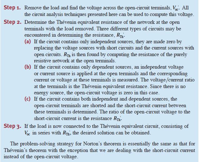
35 Linear Circuit A a + v! b i LOAD B Any Circuit!V Th + i " R Th + v = 0 v = V Th! i " R Th the load draws current i and results in voltage v 35
36 Thevenin Equivalent of Circuit A A a + v! b i LOAD B Any Circuit v = V Th! i " R Th The values of V Th (Thevenin voltage) and R Th may be either positive or negative R Th - the Thevenin resistance is a quantity in a mathematical model - it is not a physical resistor 36
37 A a + v! b i LOAD B Any Circuit v = V Th! i " R Th How to calculate the Thevenin Voltage V Th? Assume i = 0 (open circuit circuit - no external load)! v = V Th V Th = v oc 37

38 Norton Equivalent of Circuit A I N A I N = V Th R Th R Th a + v! b i LOAD B Any Circuit How to calculate the Norton Current I N? v v = V Th! i " R Th! = V Th! i R Th! R Th I N v = V Th! i " R Th Assume v = 0 (short circuit)! I N = i sc 38
39 R Th - The Thevenin Resistance 1. The most general way in obtaining R Th is to use R Th = V Th I N, where V Th = v oc - open circuit voltage I N = i sc - short circuit current 39
40 2. The Thevenin resistance R Th can be determined directly by a source suppression method without finding the Thevenin voltage and Norton current. This applies directly to circuits that contain only independent sources. This is a result of the linearity property of the circuit. R Th = V Th = V! " Th I N I N! " The Thevenin resistance remains unchanged even in the limit case when all independent sources are suppressed to zero. 40


41 (1) Replace all independent voltage sources in the circuit by short circuits and all independent current sources by open circuits A Independent Sources Deactivated a b R Th (2) If the remaining circuit contains no dependent sources, then R Th is the equivalent resistance, which can be determined by using series/parallel resistor combinations. 41
42 A. Thevenin and Norton Equivalent for Circuits with Independent Sources Example Find a Thevenin/Norton Equivalent 1. Open circuit voltage at a! b: v ab = v 1! the voltage across the 3 A source KCL : v 1! v 1 20! 3 = 0! v 1 = 32V v oc = 32 V 42

43 2. Short circuit current at a! b: KCL: v 2! v 2 20! 3+ v 2 4 = 0! v 2 = 16 V i sc = 16 4 = 4A! R Th = v oc i sc = 32 4 = 8! 43
44 The Thevenin Equivalent The Norton Equivalent 44
45 The Thevenin resistance R Th R Th = = 8! 45
46 The circuit with load 24! V 24! = I 24! = 24V 24! = 1A " 32 = 24V 24! 46

47 Example Open circuit voltage V oc = 3+ V 1, V 1 = ( 2!10 "3 )! 3k = 6V! V oc = 9V 47

48 2. Short circuit current I sc = 2m + I 1 = 2m + 3V 3k = 2m +1m = 3mA 48

49 3. R Th R Th = 3k!! 49

50 4. The circuit with load V 0 = ! 9 = 6V 50

51 Example 5.6 Find V 0 12V 51

52 1. Open circuit voltage and R Th V oc1 = V 6k = 6!12 = 8V R Th = = 4k! 52

53 2. Circuit with load 53

54 3 Second Iteration 54


55 3.1. Open circuit voltage and R Th V oc2 = 8 + 2m! 4k = 16V R Th = 4k! 55

56 4. Circuit with load 16V V 0 = !16 = 8V 56

57 Example 5.7 Find V 0 57
 = 0 # $ % I 2 = 2m! I 1 = 5 / 3 ma KVL: V oc = 4k! I 1 + 2k!")
58 1. Open circuit voltage and R Th Mesh-Current Method:!6 + 4k " I 1 + 2k " ( I 1! I 2 ) = 0 # $ % I 2 = 2m! I 1 = 5 / 3 ma KVL: V oc = 4k! I 1 + 2k! I 2 " V oc = = 32 3 V 58

59 R Th R Th = = 10 3 k! Note: I sc = V oc R Th = 32 / 3 10 / 3 = 3.2mA 59

60 2. Thevenin Equivalent with Load Thevenin V 0 = ! 32 3 = 48 7 V = V! 7 V! 60
61 B. Thevenin and Norton Equivalent for Circuits with Dependent Sources Valid and Invalid Partitions We cannot split the dependent source and its controlling variable when we break the circuit to find the equivalent Thevenin/Norton circuits 61
62 B1 Thevenin/Norton Equivalent for Circuits with Only Dependent Sources: Test Source Approach I 0 R Th = 1V I 0 V 0 R Th = V 0 1mA 62

63 Example 5.8 Find R Th I 0 R Th = 1V I 0 V oc =? Thevenin equivalent? 63

64 KVL (big loop):!v 1! V x +1 = 0! V 1 = 1! V x KCL (at V 1 ): V 1 1k + V! 2V 1 x 2k + V 1!1 1k = 0! V x = 3 7 V I 0 = I 1 + I 2 + I 3! I 1 = V x 1k = 3 7 ma, I = 1! 2V x 2 1k! I 0 = ma! R Th = 1 V I 0 = k! 64 = 1 7 ma, I 3 = 1 2k = 1 2 ma
65 Example 5. 9 Find R Th V oc =? Thevenin equivalent? 65
66 V 1 V 2 R Th = V 2 1 ma KCL: V 1 : V 1! 2000I x 2k + V 1 1k + V! V 1 2 3k = 0! I x = V 1 1k V 2 : V 2! V 1 3k + V 2 2k!1m = 0! V 2 = 10 7 V! R Th = V 2 1 ma = 10 7 k! 66

67 B2 Thevenin/Norton Equivalent for Circuits with Both Independent and Dependent Sources Example 5.10 Find V 0 67
 + 2000I x 1k + V oc +12 2k")
68 V oc +12 supernode 1. Open circuit voltage KCL at the supernode: ' ( V oc +12) I x 1k + V oc +12 2k + V oc! 2k I x ' = 0 Since I x ' = V oc 2k! V oc =!6V! V Th 68


69 2. Short circuit current and R Th! I sc =! k =! 12 2 / 3k =!18mA R Th = V oc I sc =!6V!18mA = 1 3 k!! R Th 69
 = \" 18 7 V = - 2.57 70")
70 3. Circuit with Load Thevenin V o = ! ("6) = " 18 7 V =
71 Example Find Thevenin Equivalent 1. Open circuit voltage V Th = v ab = v 25! = v Since i x = 0! V Th = (!20i) " 25 =!500i i = 5! 3v 2k! = 5! 3V Th 2k! V Th =!5V 71

72 2. Short circuit current and R Th! v = 0! i sc =!20i, i = 5 2k = 2.5mA! i sc =!20 " 2.5 =!50mA R Th = V Th i sc =!5!50m = 100" 72
73 Find the Thevenin Equivalent R Th Using a Test Source The equivalent method is to first deactivate all independent sources and then apply either a test voltage source or a test current source The Thevenin resistance R Th is calculated as R Th = V test I 0 R Th = V 0 I test 73
74 Example Deactivate the independent sources and excite the circuit by a test source Note: Use, e.g., v T = 1V 74
75 R Th = v T i T i T! v T 25! 20i = 0! i T = v T i i =!3v T 2k =! 3 2 v ma T! i T = v T ! # " 3 2 v ma & T $ % ' ( = = v T 25! v T! i T v T = 1 25! = 1 100! R Th = v T i T = 100! 75
76 76
77 5. 5 Maximum Power Transfer Circuit analysis plays an important role in the analysis of systems designed to transfer power from a source to a load. The efficiency of the power transfer: power utility systems are a good example of this type because they are concerned with the generation, transmission, and distribution of large quantities of electric power. If a power utility system is inefficient, a large percentage of the power generated is lost in the transmission and distribution processes, and thus wasted. Power transferred: communication and instrumentation systems are good examples because in the transmission of information, or data, via electric signals, the power available at the transmitter or detector is limited. Thus, transmitting as much of this power as possible to the receiver, or load, is desirable. In such applications the amount of power being transferred is small, so the efficiency of transfer is not a primary concern. 77
78 We consider maximum power transfer in systems that can be modeled by a purely resistive circuit. We wish to determine the value of of R L that permits maximum power delivery to R L 78

79 Represent the Resistive Network by its Thevenin Equivalent P load = i 2 R L =! " # V Th R Th + R L 2 $ % & R L ' max RL 79
80 P load =! " # V Th R Th + R L 2 $ % & R L P load R L 80
81 Maximum is reached at the point where dp load dr L = 0! P load = " # $ V Th R Th + R L 2 % & ' R L dp load dr L 2 d = V Th dr L!# " $# R L ( ) 2 R Th + R L %# & '# ( ) 2! 2R L ( R Th + R L ) ( ) 4 " 2 R = V Th + R L Th $ # $ R Th + R L % ' &' = 0 81
82 Condition for Maximum Power Transfer R L = R Th The Maximum Power Delivered to R L P load =! " # V Th R Th + R L 2 $ % & R L! P =! V Th max " R L =R Th # 2R Th 2 $ % & R Th P max = V Th 2 4R Th 82

83 Example Find R L that results in max. power and the corresponding max. power that can be delivered to R L. V Th = ! 360 = 300 V R Th = = 25! 83
84 P load =! " # V Th R Th + R L 2 $ % & R L =! 300 " # 25 + R L 2 $ % & R L P load! R L = 25! for the maximum power transfer with 84 R L 2! 300 $ P max = " % 25 = 900W # &

85 Example Find R L that results in max. power and the corresponding max. power that can be delivered to R L. 85

86 1. R Th R Th = 4k + 3k 6k = 6k This is the resistance for maximum power transfer If must find the value of the power that can be transferred then we need the Thevenin voltage! 86

87 2. V oc * loop 1: I 1 = 2mA * loop 2: 3k( I 2! I 1 ) + 6kI 2 + 3V = 0! I 2 = 1 3 ma * KVL: V oc! 6kI 2! 4kI 1 = 0! V oc1 = 10V * P max = V 2 Th = 4R Th ! 6k = 25 6 mw 87

88 Example Find R L that results in max. power and the corresponding max. power that can be delivered to R L. 88
89 1. Open circuit voltage V oc V oc! 2000I x ' KCL at the supernode: V oc! 2000I x ' 3k +1k + V oc 2k! 4m = 0 and I ' x = V oc 2k! V oc = 8V 89


90 2. Short circuit current I sc and R Th I x '' = 0! dependent source is zero! I sc = 4mA R Th = 8V 4mA = 2k! 90
91 3. Circuit with Load 6 P load ==! 8V " # 6k + R L 2 $ % & R L is maximized by R L = 6k! The maximum power transfer: P max =! 8V " # 6k + 6k 2 $ % & 6k = 8 3 mw 91
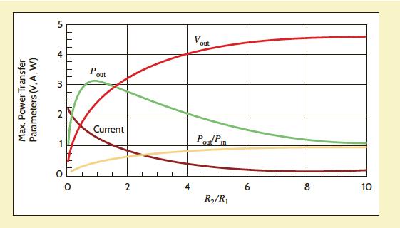
92 Example Plot V out, I, P in, P out and P out / P in as a function of R 2 92
93 * V out = R 2 R 1 + R 2 V in ; * I = V in R 1 + R 2 * P in = I! V in = V in 2 R 1 + R 2 * P out = I! V out =! " # V in R 1 + R 2 $ % & 2 R 2 * efficiency = P out P in = R 2 R 1 + R 2 = 1 1+ R 1 / R 2 93
94
95 * As R 2! then V out! V in = 5 V * As R 2! then I! * small R 2! V out is small, large R 2! I is small! * maximum power transfer ( R 2 / R 1 = 1) does not correspond to max. efficiency * At R 2 / R 1 = 1! efficiency = P out P in = 0.5 (50%) * The fact that the eff. is higher for R 2 > R 1 is due to the fact that a higher percentage of the source power is transferred to the load (more $ for MH), but the value of the load power is lower since the total circuit resistance goes up maximum power transfer! 2R 1 < R 1 + R 2 95
96 96
ECE2262 Electric Circuits. Chapter 5: Circuit Theorems
 ECE2262 Electric Circuits Chapter 5: Circuit Theorems 1 Equivalence Linearity Superposition Thevenin s and Norton s Theorems Maximum Power Transfer Analysis of Circuits Using Circuit Theorems 2 5. 1 Equivalence
Circuit Theorems Overview Linearity Superposition Source Transformation Thévenin and Norton Equivalents Maximum Power Transfer
 Circuit Theorems Overview Linearity Superposition Source Transformation Thévenin and Norton Equivalents Maximum Power Transfer J. McNames Portland State University ECE 221 Circuit Theorems Ver. 1.36 1
Chapter 5. Department of Mechanical Engineering
 Source Transformation By KVL: V s =ir s + v By KCL: i s =i + v/r p is=v s /R s R s =R p V s /R s =i + v/r s i s =i + v/r p Two circuits have the same terminal voltage and current Source Transformation
3.1 Superposition theorem
 Many electric circuits are complex, but it is an engineer s goal to reduce their complexity to analyze them easily. In the previous chapters, we have mastered the ability to solve networks containing independent
CHAPTER 4. Circuit Theorems
 CHAPTER 4 Circuit Theorems The growth in areas of application of electrical circuits has led to an evolution from simple to complex circuits. To handle such complexity, engineers over the years have developed
UNIT 4 DC EQUIVALENT CIRCUIT AND NETWORK THEOREMS
 UNIT 4 DC EQUIVALENT CIRCUIT AND NETWORK THEOREMS 1.0 Kirchoff s Law Kirchoff s Current Law (KCL) states at any junction in an electric circuit the total current flowing towards that junction is equal
Chapter 10: Sinusoidal Steady-State Analysis
 Chapter 10: Sinusoidal Steady-State Analysis 10.1 10.2 10.3 10.4 10.5 10.6 10.9 Basic Approach Nodal Analysis Mesh Analysis Superposition Theorem Source Transformation Thevenin & Norton Equivalent Circuits
Chapter 4. Techniques of Circuit Analysis
 Chapter 4. Techniques of Circuit Analysis By: FARHAD FARADJI, Ph.D. Assistant Professor, Electrical Engineering, K.N. Toosi University of Technology http://wp.kntu.ac.ir/faradji/electriccircuits1.htm Reference:
Chapter 10 AC Analysis Using Phasors
 Chapter 10 AC Analysis Using Phasors 10.1 Introduction We would like to use our linear circuit theorems (Nodal analysis, Mesh analysis, Thevenin and Norton equivalent circuits, Superposition, etc.) to
CHAPTER FOUR CIRCUIT THEOREMS
 4.1 INTRODUCTION CHAPTER FOUR CIRCUIT THEOREMS The growth in areas of application of electric circuits has led to an evolution from simple to complex circuits. To handle the complexity, engineers over
Sinusoidal Steady State Analysis (AC Analysis) Part II
 Part II") Sinusoidal Steady State Analysis (AC Analysis) Part II Amin Electronics and Electrical Communications Engineering Department (EECE) Cairo University elc.n102.eng@gmail.com http://scholar.cu.edu.eg/refky/
Sinusoidal Steady State Analysis (AC Analysis) Part II Amin Electronics and Electrical Communications Engineering Department (EECE) Cairo University elc.n102.eng@gmail.com http://scholar.cu.edu.eg/refky/
Notes for course EE1.1 Circuit Analysis TOPIC 3 CIRCUIT ANALYSIS USING SUB-CIRCUITS
 Notes for course EE1.1 Circuit Analysis 2004-05 TOPIC 3 CIRCUIT ANALYSIS USING SUB-CIRCUITS OBJECTIVES 1) To introduce the Source Transformation 2) To consider the concepts of Linearity and Superposition
D C Circuit Analysis and Network Theorems:
 UNIT-1 D C Circuit Analysis and Network Theorems: Circuit Concepts: Concepts of network, Active and passive elements, voltage and current sources, source transformation, unilateral and bilateral elements,
4/27 Friday. I have all the old homework if you need to collect them.
 4/27 Friday Last HW: do not need to turn it. Solution will be posted on the web. I have all the old homework if you need to collect them. Final exam: 7-9pm, Monday, 4/30 at Lambert Fieldhouse F101 Calculator
Midterm Exam (closed book/notes) Tuesday, February 23, 2010
 Tuesday, February 23, 2010") University of California, Berkeley Spring 2010 EE 42/100 Prof. A. Niknejad Midterm Exam (closed book/notes) Tuesday, February 23, 2010 Guidelines: Closed book. You may use a calculator. Do not unstaple
University of California, Berkeley Spring 2010 EE 42/100 Prof. A. Niknejad Midterm Exam (closed book/notes) Tuesday, February 23, 2010 Guidelines: Closed book. You may use a calculator. Do not unstaple
Notes for course EE1.1 Circuit Analysis TOPIC 10 2-PORT CIRCUITS
 Objectives: Introduction Notes for course EE1.1 Circuit Analysis 4-5 Re-examination of 1-port sub-circuits Admittance parameters for -port circuits TOPIC 1 -PORT CIRCUITS Gain and port impedance from -port
Sinusoidal Steady State Analysis (AC Analysis) Part I
 Part I") Sinusoidal Steady State Analysis (AC Analysis) Part I Amin Electronics and Electrical Communications Engineering Department (EECE) Cairo University elc.n102.eng@gmail.com http://scholar.cu.edu.eg/refky/
Sinusoidal Steady State Analysis (AC Analysis) Part I Amin Electronics and Electrical Communications Engineering Department (EECE) Cairo University elc.n102.eng@gmail.com http://scholar.cu.edu.eg/refky/
ECE2262 Electric Circuit
 ECE2262 Electric Circuit Chapter 7: FIRST AND SECOND-ORDER RL AND RC CIRCUITS Response to First-Order RL and RC Circuits Response to Second-Order RL and RC Circuits 1 2 7.1. Introduction 3 4 In dc steady
UNIVERSITY F P RTLAND Sch l f Engineering
 UNIVERSITY F P RTLAND Sch l f Engineering EE271-Electrical Circuits Laboratory Spring 2004 Dr. Aziz S. Inan & Dr. Joseph P. Hoffbeck Lab Experiment #4: Electrical Circuit Theorems - p. 1 of 5 - Electrical
Electric Circuits II Sinusoidal Steady State Analysis. Dr. Firas Obeidat
 Electric Circuits II Sinusoidal Steady State Analysis Dr. Firas Obeidat 1 Table of Contents 1 2 3 4 5 Nodal Analysis Mesh Analysis Superposition Theorem Source Transformation Thevenin and Norton Equivalent
Thevenin equivalent circuits
 Thevenin equivalent circuits We have seen the idea of equivalency used in several instances already. 1 2 1 2 same as 1 2 same as 1 2 R 3 same as = 0 V same as 0 A same as same as = EE 201 Thevenin 1 The
Chapter 5: Circuit Theorems
 Chapter 5: Circuit Theorems This chapter provides a new powerful technique of solving complicated circuits that are more conceptual in nature than node/mesh analysis. Conceptually, the method is fairly
Thevenin Norton Equivalencies - GATE Study Material in PDF
 Thevenin Norton Equivalencies - GATE Study Material in PDF In these GATE 2018 Notes, we explain the Thevenin Norton Equivalencies. Thevenin s and Norton s Theorems are two equally valid methods of reducing
Series & Parallel Resistors 3/17/2015 1
 Series & Parallel Resistors 3/17/2015 1 Series Resistors & Voltage Division Consider the single-loop circuit as shown in figure. The two resistors are in series, since the same current i flows in both
EECE251 Circuit Analysis I Lecture Integrated Program Set 3: Circuit Theorems
 EECE251 Circuit Analysis I Lecture Integrated Program Set 3: Circuit Theorems Shahriar Mirabbasi Department of Electrical and Computer Engineering University of British Columbia shahriar@ece.ubc.ca 1 Linearity
Lecture Notes on DC Network Theory
 Federal University, Ndufu-Alike, Ikwo Department of Electrical/Electronics and Computer Engineering (ECE) Faculty of Engineering and Technology Lecture Notes on DC Network Theory Harmattan Semester by
Chapter 5 Objectives
 Chapter 5 Engr228 Circuit Analysis Dr Curtis Nelson Chapter 5 Objectives State and apply the property of linearity State and apply the property of superposition Investigate source transformations Define
Chapter 2 Resistive Circuits
 1. Sole circuits (i.e., find currents and oltages of interest) by combining resistances in series and parallel. 2. Apply the oltage-diision and current-diision principles. 3. Sole circuits by the node-oltage
Chapter 5 Solution P5.2-2, 3, 6 P5.3-3, 5, 8, 15 P5.4-3, 6, 8, 16 P5.5-2, 4, 6, 11 P5.6-2, 4, 9
 Chapter 5 Solution P5.2-2, 3, 6 P5.3-3, 5, 8, 15 P5.4-3, 6, 8, 16 P5.5-2, 4, 6, 11 P5.6-2, 4, 9 P 5.2-2 Consider the circuit of Figure P 5.2-2. Find i a by simplifying the circuit (using source transformations)
Chapter 4 Circuit Theorems
 Chapter 4 Circuit Theorems 1. Linearity and Proportionality. Source Transformation 3. Superposition Theorem 4. Thevenin s Theorem and Norton s Theorem 5. Maximum Power Transfer Theorem Mazita Sem 1 111
Chapter 10 Sinusoidal Steady State Analysis Chapter Objectives:
 Chapter 10 Sinusoidal Steady State Analysis Chapter Objectives: Apply previously learn circuit techniques to sinusoidal steady-state analysis. Learn how to apply nodal and mesh analysis in the frequency
EIT Review. Electrical Circuits DC Circuits. Lecturer: Russ Tatro. Presented by Tau Beta Pi The Engineering Honor Society 10/3/2006 1
 EIT Review Electrical Circuits DC Circuits Lecturer: Russ Tatro Presented by Tau Beta Pi The Engineering Honor Society 10/3/2006 1 Session Outline Basic Concepts Basic Laws Methods of Analysis Circuit
ECE 1311: Electric Circuits. Chapter 2: Basic laws
 ECE 1311: Electric Circuits Chapter 2: Basic laws Basic Law Overview Ideal sources series and parallel Ohm s law Definitions open circuits, short circuits, conductance, nodes, branches, loops Kirchhoff's
Study Notes on Network Theorems for GATE 2017
 Study Notes on Network Theorems for GATE 2017 Network Theorems is a highly important and scoring topic in GATE. This topic carries a substantial weight age in GATE. Although the Theorems might appear to
EE-201 Review Exam I. 1. The voltage Vx in the circuit below is: (1) 3V (2) 2V (3) -2V (4) 1V (5) -1V (6) None of above
 3V (2) 2V (3) -2V (4) 1V (5) -1V (6) None of above") EE-201, Review Probs Test 1 page-1 Spring 98 EE-201 Review Exam I Multiple Choice (5 points each, no partial credit.) 1. The voltage Vx in the circuit below is: (1) 3V (2) 2V (3) -2V (4) 1V (5) -1V (6)
EE-201, Review Probs Test 1 page-1 Spring 98 EE-201 Review Exam I Multiple Choice (5 points each, no partial credit.) 1. The voltage Vx in the circuit below is: (1) 3V (2) 2V (3) -2V (4) 1V (5) -1V (6)
 Network Topology-2 & Dual and Duality Choice of independent branch currents and voltages: The solution of a network involves solving of all branch currents and voltages. We know that the branch current
Electrical Circuits I Lecture 8
 Electrical Circuits I Lecture 8 Thevenin and Norton theorems Thevenin theorem tells us that we can replace the entire network, exclusive of the load resistor, by an equivalent circuit
EE292: Fundamentals of ECE
 EE292: Fundamentals of ECE Fall 2012 TTh 10:00-11:15 SEB 1242 Lecture 4 120906 http://www.ee.unlv.edu/~b1morris/ee292/ 2 Outline Review Voltage Divider Current Divider Node-Voltage Analysis 3 Network Analysis
EECE208 Intro to Electrical Engineering Lab. 5. Circuit Theorems - Thevenin Theorem, Maximum Power Transfer, and Superposition
 EECE208 Intro to Electrical Engineering Lab Dr. Charles Kim 5. Circuit Theorems - Thevenin Theorem, Maximum Power Transfer, and Superposition Objectives: This experiment emphasizes e following ree circuit
POLYTECHNIC UNIVERSITY Electrical Engineering Department. EE SOPHOMORE LABORATORY Experiment 2 DC circuits and network theorems
 POLYTECHNIC UNIVERSITY Electrical Engineering Department EE SOPHOMORE LABORATORY Experiment 2 DC circuits and network theorems Modified for Physics 18, Brooklyn College I. Overview of Experiment In this
Electric Circuits I. Midterm #1
 The University of Toledo Section number s5ms_elci7.fm - Electric Circuits I Midterm # Problems Points. 3 2. 7 3. 5 Total 5 Was the exam fair? yes no The University of Toledo Section number s5ms_elci7.fm
MAE140 - Linear Circuits - Fall 14 Midterm, November 6
 MAE140 - Linear Circuits - Fall 14 Midterm, November 6 Instructions (i) This exam is open book. You may use whatever written materials you choose, including your class notes and textbook. You may use a
Basic Electrical Circuits Analysis ECE 221
 Basic Electrical Circuits Analysis ECE 221 PhD. Khodr Saaifan http://trsys.faculty.jacobs-university.de k.saaifan@jacobs-university.de 1 2 Reference: Electric Circuits, 8th Edition James W. Nilsson, and
BFF1303: ELECTRICAL / ELECTRONICS ENGINEERING. Alternating Current Circuits : Basic Law
 BFF1303: ELECTRICAL / ELECTRONICS ENGINEERING Alternating Current Circuits : Basic Law Ismail Mohd Khairuddin, Zulkifil Md Yusof Faculty of Manufacturing Engineering Universiti Malaysia Pahang Alternating
SOME USEFUL NETWORK THEOREMS
 APPENDIX D SOME USEFUL NETWORK THEOREMS Introduction In this appendix we review three network theorems that are useful in simplifying the analysis of electronic circuits: Thévenin s theorem Norton s theorem
Chapter 2 Resistive Circuits
 Chapter esistie Circuits Goal. Sole circuits by combining resistances in Series and Parallel.. Apply the Voltage-Diision and Current-Diision Principles.. Sole circuits by the Node-Voltage Technique.. Sole
ECE2262 Electric Circuits. Chapter 4: Operational Amplifier (OP-AMP) Circuits
 Circuits") ECE2262 Electric Circuits Chapter 4: Operational Amplifier (OP-AMP) Circuits 1 4.1 Operational Amplifiers 2 4. Voltages and currents in electrical circuits may represent signals and circuits can perform
ECE2262 Electric Circuits Chapter 4: Operational Amplifier (OP-AMP) Circuits 1 4.1 Operational Amplifiers 2 4. Voltages and currents in electrical circuits may represent signals and circuits can perform
The equivalent model of a certain op amp is shown in the figure given below, where R 1 = 2.8 MΩ, R 2 = 39 Ω, and A =
 The equivalent model of a certain op amp is shown in the figure given below, where R 1 = 2.8 MΩ, R 2 = 39 Ω, and A = 10 10 4. Section Break Difficulty: Easy Learning Objective: Understand how real operational
R 2, R 3, and R 4 are in parallel, R T = R 1 + (R 2 //R 3 //R 4 ) + R 5. C-C Tsai
 + R 5. C-C Tsai") Chapter 07 Series-Parallel Circuits The Series-Parallel Network Complex circuits May be separated both series and/or parallel elements Combinations which are neither series nor parallel To analyze a circuit
Chapter 07 Series-Parallel Circuits The Series-Parallel Network Complex circuits May be separated both series and/or parallel elements Combinations which are neither series nor parallel To analyze a circuit
Homework 3 Solution. Due Friday (5pm), Feb. 14, 2013
, Feb. 14, 2013") University of California, Berkeley Spring 2013 EE 42/100 Prof. K. Pister Homework 3 Solution Due Friday (5pm), Feb. 14, 2013 Please turn the homework in to the drop box located next to 125 Cory Hall (labeled
University of California, Berkeley Spring 2013 EE 42/100 Prof. K. Pister Homework 3 Solution Due Friday (5pm), Feb. 14, 2013 Please turn the homework in to the drop box located next to 125 Cory Hall (labeled
Introduction to AC Circuits (Capacitors and Inductors)
") Introduction to AC Circuits (Capacitors and Inductors) Amin Electronics and Electrical Communications Engineering Department (EECE) Cairo University elc.n102.eng@gmail.com http://scholar.cu.edu.eg/refky/
Introduction to AC Circuits (Capacitors and Inductors) Amin Electronics and Electrical Communications Engineering Department (EECE) Cairo University elc.n102.eng@gmail.com http://scholar.cu.edu.eg/refky/
DC STEADY STATE CIRCUIT ANALYSIS
 DC STEADY STATE CIRCUIT ANALYSIS 1. Introduction The basic quantities in electric circuits are current, voltage and resistance. They are related with Ohm s law. For a passive branch the current is: I=
ELEC 250: LINEAR CIRCUITS I COURSE OVERHEADS. These overheads are adapted from the Elec 250 Course Pack developed by Dr. Fayez Guibaly.
 Elec 250: Linear Circuits I 5/4/08 ELEC 250: LINEAR CIRCUITS I COURSE OVERHEADS These overheads are adapted from the Elec 250 Course Pack developed by Dr. Fayez Guibaly. S.W. Neville Elec 250: Linear Circuits
Module 2. DC Circuit. Version 2 EE IIT, Kharagpur
 Module DC Circuit Lesson 4 Loop Analysis of resistive circuit in the context of dc voltages and currents Objectives Meaning of circuit analysis; distinguish between the terms mesh and loop. To provide
ENGG 225. David Ng. Winter January 9, Circuits, Currents, and Voltages... 5
 ENGG 225 David Ng Winter 2017 Contents 1 January 9, 2017 5 1.1 Circuits, Currents, and Voltages.................... 5 2 January 11, 2017 6 2.1 Ideal Basic Circuit Elements....................... 6 3 January
15.9 TWO-PORTS* . (15.114) R Thout = v 2a
 R Thout = v 2a") 15.9 TWOPORTS* It should be obvious by now that circuits with dependent sources can perform much more interesting and useful signal processing than those constructed solely from twoterminal resistive elements.
15.9 TWOPORTS* It should be obvious by now that circuits with dependent sources can perform much more interesting and useful signal processing than those constructed solely from twoterminal resistive elements.
Chapter 2. Engr228 Circuit Analysis. Dr Curtis Nelson
 Chapter 2 Engr228 Circuit Analysis Dr Curtis Nelson Chapter 2 Objectives Understand symbols and behavior of the following circuit elements: Independent voltage and current sources; Dependent voltage and
E1.1 Analysis of Circuits ( ) Revision Lecture 1 1 / 13
 Revision Lecture 1 1 / 13") RevisionLecture 1: E1.1 Analysis of Circuits (2014-4530) Revision Lecture 1 1 / 13 Format Question 1 (40%): eight short parts covering the whole syllabus. Questions 2 and 3: single topic questions (answer
RevisionLecture 1: E1.1 Analysis of Circuits (2014-4530) Revision Lecture 1 1 / 13 Format Question 1 (40%): eight short parts covering the whole syllabus. Questions 2 and 3: single topic questions (answer
D is the voltage difference = (V + - V - ).
.") 1 Operational amplifier is one of the most common electronic building blocks used by engineers. It has two input terminals: V + and V -, and one output terminal Y. It provides a gain A, which is usually
1 Operational amplifier is one of the most common electronic building blocks used by engineers. It has two input terminals: V + and V -, and one output terminal Y. It provides a gain A, which is usually
Homework 2. Due Friday (5pm), Feb. 8, 2013
, Feb. 8, 2013") University of California, Berkeley Spring 2013 EE 42/100 Prof. K. Pister Homework 2 Due Friday (5pm), Feb. 8, 2013 Please turn the homework in to the drop box located next to 125 Cory Hall (labeled EE
University of California, Berkeley Spring 2013 EE 42/100 Prof. K. Pister Homework 2 Due Friday (5pm), Feb. 8, 2013 Please turn the homework in to the drop box located next to 125 Cory Hall (labeled EE
Module 2. DC Circuit. Version 2 EE IIT, Kharagpur
 Module 2 DC Circuit Lesson 5 Node-voltage analysis of resistive circuit in the context of dc voltages and currents Objectives To provide a powerful but simple circuit analysis tool based on Kirchhoff s
ECE 212H1F Circuit Analysis October 20, :15-19: Reza Iravani 02 Reza Iravani 03 Ali Nabavi-Niaki. (Non-programmable Calculators Allowed)
") Please Print Clearly Last Name: First Name: Student Number: Your Tutorial Section (CIRCLE ONE): 01 Thu 10:00 12:00 HA403 02 Thu 10:00 12:00 GB412 03 Thu 15:00 17:00 GB412 04 Thu 15:00 17:00 SF2202 05 Fri
Please Print Clearly Last Name: First Name: Student Number: Your Tutorial Section (CIRCLE ONE): 01 Thu 10:00 12:00 HA403 02 Thu 10:00 12:00 GB412 03 Thu 15:00 17:00 GB412 04 Thu 15:00 17:00 SF2202 05 Fri
Lecture #3. Review: Power
 Lecture #3 OUTLINE Power calculations Circuit elements Voltage and current sources Electrical resistance (Ohm s law) Kirchhoff s laws Reading Chapter 2 Lecture 3, Slide 1 Review: Power If an element is
mywbut.com Mesh Analysis
 Mesh Analysis 1 Objectives Meaning of circuit analysis; distinguish between the terms mesh and loop. To provide more general and powerful circuit analysis tool based on Kirchhoff s voltage law (KVL) only.
Chapter 7. Chapter 7
 Chapter 7 Combination circuits Most practical circuits have combinations of series and parallel components. You can frequently simplify analysis by combining series and parallel components. An important
Designing Information Devices and Systems I Fall 2018 Lecture Notes Note Introduction: Op-amps in Negative Feedback
 EECS 16A Designing Information Devices and Systems I Fall 2018 Lecture Notes Note 18 18.1 Introduction: Op-amps in Negative Feedback In the last note, we saw that can use an op-amp as a comparator. However,
CURRENT SOURCES EXAMPLE 1 Find the source voltage Vs and the current I1 for the circuit shown below SOURCE CONVERSIONS
 CURRENT SOURCES EXAMPLE 1 Find the source voltage Vs and the current I1 for the circuit shown below EXAMPLE 2 Find the source voltage Vs and the current I1 for the circuit shown below SOURCE CONVERSIONS
Lecture 8: 09/18/03 A.R. Neureuther Version Date 09/14/03 EECS 42 Introduction Digital Electronics Andrew R. Neureuther
 EECS ntroduction Digital Electronics ndrew. Neureuther Lecture #8 Node Equations Systematic Node Equations Example: oltage and Current Dividers Example 5 Element Circuit Schwarz and Oldham 5-58,.5, &.6
Module 2. DC Circuit. Version 2 EE IIT, Kharagpur
 Module 2 DC Circuit esson 8 evenin s and Norton s theorems in the context of dc voltage and current sources acting in a resistive network Objectives To understand the basic philosophy behind the evenin
Chapter 4: Techniques of Circuit Analysis
 Chapter 4: Techniques of Circuit Analysis This chapter gies us many useful tools for soling and simplifying circuits. We saw a few simple tools in the last chapter (reduction of circuits ia series and
MAE140 HW3 Solutions
 MAE40 HW Solutions.7) Method: Remove load resistor and find Thevenin equivalent circuit VOC 600 450 00 450 To find Isc, use a voltage divider at a a 00 450 00 450 00 600 0 0 900 6 Isc Isc 00 6*00 00 Amps
1. Review of Circuit Theory Concepts
 1. Review of Circuit Theory Concepts Lecture notes: Section 1 ECE 65, Winter 2013, F. Najmabadi Circuit Theory is an pproximation to Maxwell s Electromagnetic Equations circuit is made of a bunch of elements
Electric Circuits I. Nodal Analysis. Dr. Firas Obeidat
 Electric Circuits I Nodal Analysis Dr. Firas Obeidat 1 Nodal Analysis Without Voltage Source Nodal analysis, which is based on a systematic application of Kirchhoff s current law (KCL). A node is defined
Operational amplifiers (Op amps)
") Operational amplifiers (Op amps) Recall the basic two-port model for an amplifier. It has three components: input resistance, Ri, output resistance, Ro, and the voltage gain, A. v R o R i v d Av d v Also
Operational amplifiers (Op amps) Recall the basic two-port model for an amplifier. It has three components: input resistance, Ri, output resistance, Ro, and the voltage gain, A. v R o R i v d Av d v Also
Basics of Network Theory (Part-I)
") Basics of Network Theory (PartI). A square waveform as shown in figure is applied across mh ideal inductor. The current through the inductor is a. wave of peak amplitude. V 0 0.5 t (m sec) [Gate 987: Marks]
Basics of Network Theory (PartI). A square waveform as shown in figure is applied across mh ideal inductor. The current through the inductor is a. wave of peak amplitude. V 0 0.5 t (m sec) [Gate 987: Marks]
DEPARTMENT OF COMPUTER ENGINEERING UNIVERSITY OF LAHORE
 DEPARTMENT OF COMPUTER ENGINEERING UNIVERSITY OF LAHORE NAME. Section 1 2 3 UNIVERSITY OF LAHORE Department of Computer engineering Linear Circuit Analysis Laboratory Manual 2 Compiled by Engr. Ahmad Bilal
Experiment #6. Thevenin Equivalent Circuits and Power Transfer
 Experiment #6 Thevenin Equivalent Circuits and Power Transfer Objective: In this lab you will confirm the equivalence between a complicated resistor circuit and its Thevenin equivalent. You will also learn
Voltage Dividers, Nodal, and Mesh Analysis
 Engr228 Lab #2 Voltage Dividers, Nodal, and Mesh Analysis Name Partner(s) Grade /10 Introduction This lab exercise is designed to further your understanding of the use of the lab equipment and to verify
Homework 1 solutions
 Electric Circuits 1 Homework 1 solutions (Due date: 2014/3/3) This assignment covers Ch1 and Ch2 of the textbook. The full credit is 100 points. For each question, detailed derivation processes and accurate
Notes for course EE1.1 Circuit Analysis TOPIC 4 NODAL ANALYSIS
 Notes for course EE1.1 Circuit Analysis 2004-05 TOPIC 4 NODAL ANALYSIS OBJECTIVES 1) To develop Nodal Analysis of Circuits without Voltage Sources 2) To develop Nodal Analysis of Circuits with Voltage
Figure Circuit for Question 1. Figure Circuit for Question 2
 Exercises 10.7 Exercises Multiple Choice 1. For the circuit of Figure 10.44 the time constant is A. 0.5 ms 71.43 µs 2, 000 s D. 0.2 ms 4 Ω 2 Ω 12 Ω 1 mh 12u 0 () t V Figure 10.44. Circuit for Question
1.7 Delta-Star Transformation
 S Electronic ircuits D ircuits 8.7 Delta-Star Transformation Fig..(a) shows three resistors R, R and R connected in a closed delta to three terminals, and, their numerical subscripts,, and, being opposite
Kirchhoff's Laws and Circuit Analysis (EC 2)
") Kirchhoff's Laws and Circuit Analysis (EC ) Circuit analysis: solving for I and V at each element Linear circuits: involve resistors, capacitors, inductors Initial analysis uses only resistors Power sources,
Kirchhoff's Laws and Circuit Analysis (EC ) Circuit analysis: solving for I and V at each element Linear circuits: involve resistors, capacitors, inductors Initial analysis uses only resistors Power sources,
MAE140 - Linear Circuits - Winter 09 Midterm, February 5
 Instructions MAE40 - Linear ircuits - Winter 09 Midterm, February 5 (i) This exam is open book. You may use whatever written materials you choose, including your class notes and textbook. You may use a
MAE140 Linear Circuits Fall 2016 Final, December 6th Instructions
 MAE40 Linear Circuits Fall 206 Final, December 6th Instructions. This exam is open book. You may use whatever written materials you choose, including your class notes and textbook. You may use a handheld
Solution: Based on the slope of q(t): 20 A for 0 t 1 s dt = 0 for 3 t 4 s. 20 A for 4 t 5 s 0 for t 5 s 20 C. t (s) 20 C. i (A) Fig. P1.
: 20 A for 0 t 1 s dt = 0 for 3 t 4 s. 20 A for 4 t 5 s 0 for t 5 s 20 C. t (s) 20 C. i (A) Fig. P1.") Problem 1.24 The plot in Fig. P1.24 displays the cumulative charge q(t) that has entered a certain device up to time t. Sketch a plot of the corresponding current i(t). q 20 C 0 1 2 3 4 5 t (s) 20 C Figure
Problem 1.24 The plot in Fig. P1.24 displays the cumulative charge q(t) that has entered a certain device up to time t. Sketch a plot of the corresponding current i(t). q 20 C 0 1 2 3 4 5 t (s) 20 C Figure
QUESTION BANK SUBJECT: NETWORK ANALYSIS (10ES34)
") QUESTION BANK SUBJECT: NETWORK ANALYSIS (10ES34) NOTE: FOR NUMERICAL PROBLEMS FOR ALL UNITS EXCEPT UNIT 5 REFER THE E-BOOK ENGINEERING CIRCUIT ANALYSIS, 7 th EDITION HAYT AND KIMMERLY. PAGE NUMBERS OF
QUESTION BANK SUBJECT: NETWORK ANALYSIS (10ES34) NOTE: FOR NUMERICAL PROBLEMS FOR ALL UNITS EXCEPT UNIT 5 REFER THE E-BOOK ENGINEERING CIRCUIT ANALYSIS, 7 th EDITION HAYT AND KIMMERLY. PAGE NUMBERS OF
ECE 205: Intro Elec & Electr Circuits
 ECE 205: Intro Elec & Electr Circuits Final Exam Study Guide Version 1.00 Created by Charles Feng http://www.fenguin.net ECE 205: Intro Elec & Electr Circuits Final Exam Study Guide 1 Contents 1 Introductory
Sirindhorn International Institute of Technology Thammasat University at Rangsit
 Sirindhorn International Institute of Technology Thammasat University at Rangsit School of Information, Computer and Communication Technology COURSE : ECS 304 Basic Electrical Engineering Lab INSTRUCTOR
15EE103L ELECTRIC CIRCUITS LAB RECORD
 15EE103L ELECTRIC CIRCUITS LAB RECORD REGISTER NO: NAME OF THE STUDENT: SEMESTER: DEPARTMENT: INDEX SHEET S.No. Date of Experiment Name of the Experiment Date of submission Marks Staff Sign 1 Verification
Operational amplifiers (Op amps)
") Operational amplifiers (Op amps) v R o R i v i Av i v View it as an ideal amp. Take the properties to the extreme: R i, R o 0, A.?!?!?!?! v v i Av i v A Consequences: No voltage dividers at input or output.
Operational amplifiers (Op amps) v R o R i v i Av i v View it as an ideal amp. Take the properties to the extreme: R i, R o 0, A.?!?!?!?! v v i Av i v A Consequences: No voltage dividers at input or output.
Errors in Electrical Measurements
 1 Errors in Electrical Measurements Systematic error every times you measure e.g. loading or insertion of the measurement instrument Meter error scaling (inaccurate marking), pointer bending, friction,
Ver 3537 E1.1 Analysis of Circuits (2014) E1.1 Circuit Analysis. Problem Sheet 1 (Lectures 1 & 2)
 E1.1 Circuit Analysis. Problem Sheet 1 (Lectures 1 & 2)") Ver 3537 E. Analysis of Circuits () Key: [A]= easy... [E]=hard E. Circuit Analysis Problem Sheet (Lectures & ). [A] One of the following circuits is a series circuit and the other is a parallel circuit.
Ver 3537 E. Analysis of Circuits () Key: [A]= easy... [E]=hard E. Circuit Analysis Problem Sheet (Lectures & ). [A] One of the following circuits is a series circuit and the other is a parallel circuit.
University of Alabama Department of Physics and Astronomy. Problem Set 4
 University of Alabama Department of Physics and Astronomy PH 26 LeClair Fall 20 Problem Set 4. A battery has an ideal voltage V and an internal resistance r. A variable load resistance R is connected to
ECE2262 Electric Circuits. Chapter 6: Capacitance and Inductance
 ECE2262 Electric Circuits Chapter 6: Capacitance and Inductance Capacitors Inductors Capacitor and Inductor Combinations Op-Amp Integrator and Op-Amp Differentiator 1 CAPACITANCE AND INDUCTANCE Introduces
Chapter 2 Direct Current Circuits
 Chapter 2 Direct Current Circuits 2.1 Introduction Nowadays, our lives are increasingly dependent upon the availability of devices that make extensive use of electric circuits. The knowledge of the electrical
AC Circuit Analysis and Measurement Lab Assignment 8
 Electric Circuit Lab Assignments elcirc_lab87.fm - 1 AC Circuit Analysis and Measurement Lab Assignment 8 Introduction When analyzing an electric circuit that contains reactive components, inductors and
ELEC 202 Electric Circuit Analysis II Lecture 10(a) Complex Arithmetic and Rectangular/Polar Forms
 Complex Arithmetic and Rectangular/Polar Forms") Dr. Gregory J. Mazzaro Spring 2016 ELEC 202 Electric Circuit Analysis II Lecture 10(a) Complex Arithmetic and Rectangular/Polar Forms THE CITADEL, THE MILITARY COLLEGE OF SOUTH CAROLINA 171 Moultrie Street,
Dr. Gregory J. Mazzaro Spring 2016 ELEC 202 Electric Circuit Analysis II Lecture 10(a) Complex Arithmetic and Rectangular/Polar Forms THE CITADEL, THE MILITARY COLLEGE OF SOUTH CAROLINA 171 Moultrie Street,
Writing Circuit Equations
 2 C H A P T E R Writing Circuit Equations Objectives By the end of this chapter, you should be able to do the following: 1. Find the complete solution of a circuit using the exhaustive, node, and mesh
Systematic Circuit Analysis (T&R Chap 3)
") Systematic Circuit Analysis (T&R Chap 3) Nodevoltage analysis Using the voltages of the each node relative to a ground node, write down a set of consistent linear equations for these voltages Solve this
Systematic Circuit Analysis (T&R Chap 3) Nodevoltage analysis Using the voltages of the each node relative to a ground node, write down a set of consistent linear equations for these voltages Solve this