PID controllers. Laith Batarseh. PID controllers
|
|
|
- Maurice Rose
- 5 years ago
- Views:
Transcription
 2. Derivative relation (D) 3.")
1 Next Previous 24-Jan-15 Chapter six Laith Batarseh Home End The controller choice is an important step in the control process because this element is responsible of reducing the error (e ss ), rise time and overshoot There are three main types of relations proceed in the controller: 1. Proportional relation (P) 2. Derivative relation (D) 3. Integration relation (I) These three types represent the relationships between the input and the output of the controller itself The presence of the controller is important because it is the method used to control the error and reduce it 1
 U(s) A common type of this")
 U(s) K D s K p According to this")
 The output in this type is the integration of the")
2 Controller configurations Proportional controller (P) Is the simplest type and has a proportional effect on the output E(s) U(s) A common type of this controller is the amplifier Derivative controller (D) this type take the error signal and differentiate it E(s) U(s) K D s K p According to this relation, the output order is the order of the derivative of the input Integrator controller (I) The output in this type is the integration of the input E(s) K I /s U(s) 2
3 Compression between types Examples 3

4 PD controller - Block diagram where K P and K D are the proportional and derivative constants, respectively Summary of Effects of PD Control PD controller can affect the performance of a control system in the following ways: 1. Improving damping and reducing maximum overshoot. 2. Reducing rise time and settling time. 3. Increasing BW. 4. Improving GM, PM, and Mr. 5. Possibly accentuating noise at higher frequencies. 6. Possibly requiring a relatively large capacitor in circuit implementation. 4
5 Example Let us consider the following forward-path transfer function of a unity feedback control system Let us set the performance specifications as follows: Steady-state error due to unit-ramp input < Maximum overshoot < 5% Rise time t r < sec Settling time t s < sec The system block diagram can be drawn as: 5
6 We can start with satisfying the steady-state error which is due to unit-ramp input must be less than e e ss ss R K v R K v ; K v s 0 lim sg s K K k v 4500K lim 12.5K s 0 s Assume k = 181 which satisfy the condition of steady-state error With the previous value of K and adding PD controller, he forward-path transfer function of the system becomes The closed-loop transfer function is The characteristic equation is found as: 6
) which can be written as Θ r (s) = 1/s 2. The time response θ y (t) was found for KP = 1 and KD = -0.")
7 To satisfy the other requirements : Maximum overshoot < 5% Rise time t r < sec Settling time t s < sec we have to find the effect of the parameters K D and K P on the time response. The response can be found by applying Laplace inverse to the response in s-domain (i.e. Θ y (s)) which can be written as Θ r (s) = 1/s 2. The time response θ y (t) was found for KP = 1 and KD = KD = Input KD= x KD= T x KD= T 7
8 PI controller - Block diagram where K P and K I are the proportional and integration constants, respectively Design with PI Control Example Let us consider the following forward-path transfer function of a unity feedback control system from the previous example Let us set the performance specifications as follows: Steady-state error due to parabolic input t2us(t)/2 < 0.2 Maximum overshoot < 5% Rise time t,- < 0.01 sec Settling time ts < 0.02 sec 8
9 Design with PI Control Let us set K = 181, simply because this was the value used in the previous example Apparently, to satisfy a given steady-state error requirement for a parabolic input, the larger the K, the smaller K I can be. Solve for K I for the minimum steady-state error requirement of 0.2, we get the minimum value of K I to be If necessary, the value of K can be adjusted later. Design with PI Control With K = 181, the characteristic equation of the closed-loop system is Applying Routh's test to characteristic equation yields the result that the system is stable for 0<K I /Kp <
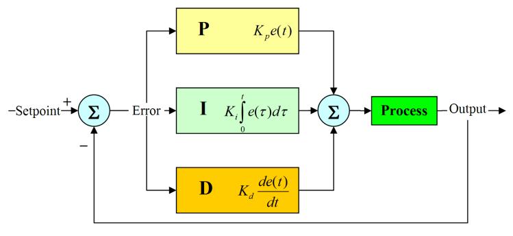
10 PID controller 10
AN INTRODUCTION TO THE CONTROL THEORY
 Open-Loop controller An Open-Loop (OL) controller is characterized by no direct connection between the output of the system and its input; therefore external disturbance, non-linear dynamics and parameter
CHAPTER 7 STEADY-STATE RESPONSE ANALYSES
 CHAPTER 7 STEADY-STATE RESPONSE ANALYSES 1. Introduction The steady state error is a measure of system accuracy. These errors arise from the nature of the inputs, system type and from nonlinearities of
MAS107 Control Theory Exam Solutions 2008
 MAS07 CONTROL THEORY. HOVLAND: EXAM SOLUTION 2008 MAS07 Control Theory Exam Solutions 2008 Geir Hovland, Mechatronics Group, Grimstad, Norway June 30, 2008 C. Repeat question B, but plot the phase curve
Automatic Control Systems (FCS) Lecture- 8 Steady State Error
 Lecture- 8 Steady State Error") Automatic Control Systems (FCS) Lecture- 8 Steady State Error Introduction Any physical control system inherently suffers steady-state error in response to certain types of inputs. A system may have no
Automatic Control Systems (FCS) Lecture- 8 Steady State Error Introduction Any physical control system inherently suffers steady-state error in response to certain types of inputs. A system may have no
(b) A unity feedback system is characterized by the transfer function. Design a suitable compensator to meet the following specifications:
 A unity feedback system is characterized by the transfer function. Design a suitable compensator to meet the following specifications:") 1. (a) The open loop transfer function of a unity feedback control system is given by G(S) = K/S(1+0.1S)(1+S) (i) Determine the value of K so that the resonance peak M r of the system is equal to 1.4.
1. (a) The open loop transfer function of a unity feedback control system is given by G(S) = K/S(1+0.1S)(1+S) (i) Determine the value of K so that the resonance peak M r of the system is equal to 1.4.
Systems Analysis and Control
 Systems Analysis and Control Matthew M. Peet Illinois Institute of Technology Lecture : Different Types of Control Overview In this Lecture, you will learn: Limits of Proportional Feedback Performance
Dr Ian R. Manchester
 Week Content Notes 1 Introduction 2 Frequency Domain Modelling 3 Transient Performance and the s-plane 4 Block Diagrams 5 Feedback System Characteristics Assign 1 Due 6 Root Locus 7 Root Locus 2 Assign
EEE 184 Project: Option 1
 EEE 184 Project: Option 1 Date: November 16th 2012 Due: December 3rd 2012 Work Alone, show your work, and comment your results. Comments, clarity, and organization are important. Same wrong result or same
UNIVERSITY OF BOLTON SCHOOL OF ENGINEERING BSC (HONS) MECHATRONICS TOP-UP SEMESTER 1 EXAMINATION 2017/2018 ADVANCED MECHATRONIC SYSTEMS
 MECHATRONICS TOP-UP SEMESTER 1 EXAMINATION 2017/2018 ADVANCED MECHATRONIC SYSTEMS") ENG08 UNIVERSITY OF BOLTON SCHOOL OF ENGINEERING BSC (HONS) MECHATRONICS TOP-UP SEMESTER EXAMINATION 07/08 ADVANCED MECHATRONIC SYSTEMS MODULE NO: MEC600 Date: 7 January 08 Time: 0.00.00 INSTRUCTIONS TO
ENG08 UNIVERSITY OF BOLTON SCHOOL OF ENGINEERING BSC (HONS) MECHATRONICS TOP-UP SEMESTER EXAMINATION 07/08 ADVANCED MECHATRONIC SYSTEMS MODULE NO: MEC600 Date: 7 January 08 Time: 0.00.00 INSTRUCTIONS TO
ELECTRONICS & COMMUNICATIONS DEP. 3rd YEAR, 2010/2011 CONTROL ENGINEERING SHEET 5 Lead-Lag Compensation Techniques
 CAIRO UNIVERSITY FACULTY OF ENGINEERING ELECTRONICS & COMMUNICATIONS DEP. 3rd YEAR, 00/0 CONTROL ENGINEERING SHEET 5 Lead-Lag Compensation Techniques [] For the following system, Design a compensator such
VALLIAMMAI ENGINEERING COLLEGE SRM Nagar, Kattankulathur
 VALLIAMMAI ENGINEERING COLLEGE SRM Nagar, Kattankulathur 603 203. DEPARTMENT OF ELECTRONICS & COMMUNICATION ENGINEERING SUBJECT QUESTION BANK : EC6405 CONTROL SYSTEM ENGINEERING SEM / YEAR: IV / II year
ECE317 : Feedback and Control
 ECE317 : Feedback and Control Lecture : Steady-state error Dr. Richard Tymerski Dept. of Electrical and Computer Engineering Portland State University 1 Course roadmap Modeling Analysis Design Laplace
IC6501 CONTROL SYSTEMS
 DHANALAKSHMI COLLEGE OF ENGINEERING CHENNAI DEPARTMENT OF ELECTRICAL AND ELECTRONICS ENGINEERING YEAR/SEMESTER: II/IV IC6501 CONTROL SYSTEMS UNIT I SYSTEMS AND THEIR REPRESENTATION 1. What is the mathematical
UNIVERSITY OF BOLTON SCHOOL OF ENGINEERING BENG (HONS) IN BIOMEDICAL ENGINEERING SEMESTER 1 EXAMINATION 2017/2018 ADVANCED BIOMECHATRONIC SYSTEMS
 IN BIOMEDICAL ENGINEERING SEMESTER 1 EXAMINATION 2017/2018 ADVANCED BIOMECHATRONIC SYSTEMS") ENG0016 UNIVERSITY OF BOLTON SCHOOL OF ENGINEERING BENG (HONS) IN BIOMEDICAL ENGINEERING SEMESTER 1 EXAMINATION 2017/2018 ADVANCED BIOMECHATRONIC SYSTEMS MODULE NO: BME6003 Date: Friday 19 January 2018
ENG0016 UNIVERSITY OF BOLTON SCHOOL OF ENGINEERING BENG (HONS) IN BIOMEDICAL ENGINEERING SEMESTER 1 EXAMINATION 2017/2018 ADVANCED BIOMECHATRONIC SYSTEMS MODULE NO: BME6003 Date: Friday 19 January 2018
Alireza Mousavi Brunel University
 Alireza Mousavi Brunel University 1 » Control Process» Control Systems Design & Analysis 2 Open-Loop Control: Is normally a simple switch on and switch off process, for example a light in a room is switched
FEEDBACK CONTROL SYSTEMS
 FEEDBAC CONTROL SYSTEMS. Control System Design. Open and Closed-Loop Control Systems 3. Why Closed-Loop Control? 4. Case Study --- Speed Control of a DC Motor 5. Steady-State Errors in Unity Feedback Control
KINGS COLLEGE OF ENGINEERING DEPARTMENT OF ELECTRONICS AND COMMUNICATION ENGINEERING
 KINGS COLLEGE OF ENGINEERING DEPARTMENT OF ELECTRONICS AND COMMUNICATION ENGINEERING QUESTION BANK SUB.NAME : CONTROL SYSTEMS BRANCH : ECE YEAR : II SEMESTER: IV 1. What is control system? 2. Define open
Control Systems. University Questions
 University Questions UNIT-1 1. Distinguish between open loop and closed loop control system. Describe two examples for each. (10 Marks), Jan 2009, June 12, Dec 11,July 08, July 2009, Dec 2010 2. Write
Exercises for lectures 13 Design using frequency methods
 Exercises for lectures 13 Design using frequency methods Michael Šebek Automatic control 2016 31-3-17 Setting of the closed loop bandwidth At the transition frequency in the open loop is (from definition)
Step input, ramp input, parabolic input and impulse input signals. 2. What is the initial slope of a step response of a first order system?
 IC6501 CONTROL SYSTEM UNIT-II TIME RESPONSE PART-A 1. What are the standard test signals employed for time domain studies?(or) List the standard test signals used in analysis of control systems? (April
Homework 7 - Solutions
 Homework 7 - Solutions Note: This homework is worth a total of 48 points. 1. Compensators (9 points) For a unity feedback system given below, with G(s) = K s(s + 5)(s + 11) do the following: (c) Find the
Unit 8: Part 2: PD, PID, and Feedback Compensation
 Ideal Derivative Compensation (PD) Lead Compensation PID Controller Design Feedback Compensation Physical Realization of Compensation Unit 8: Part 2: PD, PID, and Feedback Compensation Engineering 5821:
LABORATORY INSTRUCTION MANUAL CONTROL SYSTEM I LAB EE 593
 LABORATORY INSTRUCTION MANUAL CONTROL SYSTEM I LAB EE 593 ELECTRICAL ENGINEERING DEPARTMENT JIS COLLEGE OF ENGINEERING (AN AUTONOMOUS INSTITUTE) KALYANI, NADIA CONTROL SYSTEM I LAB. MANUAL EE 593 EXPERIMENT
Performance of Feedback Control Systems
 Performance of Feedback Control Systems Design of a PID Controller Transient Response of a Closed Loop System Damping Coefficient, Natural frequency, Settling time and Steady-state Error and Type 0, Type
Lab Experiment 2: Performance of First order and second order systems
 Lab Experiment 2: Performance of First order and second order systems Objective: The objective of this exercise will be to study the performance characteristics of first and second order systems using
Objective: To study P, PI, and PID temperature controller for an oven and compare their performance. Name of the apparatus Range Quantity
 Objective: To study P, PI, and PID temperature controller for an oven and compare their. Apparatus Used: Name of the apparatus Range Quantity 1. Temperature Controller System 1 PID Kp (0-10) Kd(0-20) Ki(0-0.02)
Root Locus Design Example #4
 Root Locus Design Example #4 A. Introduction The plant model represents a linearization of the heading dynamics of a 25, ton tanker ship under empty load conditions. The reference input signal R(s) is
Dynamic Compensation using root locus method
 CAIRO UNIVERSITY FACULTY OF ENGINEERING ELECTRONICS & COMMUNICATIONS DEP. 3rd YEAR, 00/0 CONTROL ENGINEERING SHEET 9 Dynamic Compensation using root locus method [] (Final00)For the system shown in the
CHAPTER 1 Basic Concepts of Control System. CHAPTER 6 Hydraulic Control System
 CHAPTER 1 Basic Concepts of Control System 1. What is open loop control systems and closed loop control systems? Compare open loop control system with closed loop control system. Write down major advantages
Due Wednesday, February 6th EE/MFS 599 HW #5
 Due Wednesday, February 6th EE/MFS 599 HW #5 You may use Matlab/Simulink wherever applicable. Consider the standard, unity-feedback closed loop control system shown below where G(s) = /[s q (s+)(s+9)]
Steady State Errors. Recall the closed-loop transfer function of the system, is
 Steady State Errors Outline What is steady-state error? Steady-state error in unity feedback systems Type Number Steady-state error in non-unity feedback systems Steady-state error due to disturbance inputs
Fundamental of Control Systems Steady State Error Lecturer: Dr. Wahidin Wahab M.Sc. Aries Subiantoro, ST. MSc.
 Fundamental of Control Systems Steady State Error Lecturer: Dr. Wahidin Wahab M.Sc. Aries Subiantoro, ST. MSc. Electrical Engineering Department University of Indonesia 2 Steady State Error How well can
Proportional plus Integral (PI) Controller
 Controller") Proportional plus Integral (PI) Controller 1. A pole is placed at the origin 2. This causes the system type to increase by 1 and as a result the error is reduced to zero. 3. Originally a point A is on
Proportional plus Integral (PI) Controller 1. A pole is placed at the origin 2. This causes the system type to increase by 1 and as a result the error is reduced to zero. 3. Originally a point A is on
Outline. Classical Control. Lecture 2
 Outline Outline Outline Review of Material from Lecture 2 New Stuff - Outline Review of Lecture System Performance Effect of Poles Review of Material from Lecture System Performance Effect of Poles 2 New
EE C128 / ME C134 Fall 2014 HW 8 - Solutions. HW 8 - Solutions
 EE C28 / ME C34 Fall 24 HW 8 - Solutions HW 8 - Solutions. Transient Response Design via Gain Adjustment For a transfer function G(s) = in negative feedback, find the gain to yield a 5% s(s+2)(s+85) overshoot
Radar Dish. Armature controlled dc motor. Inside. θ r input. Outside. θ D output. θ m. Gearbox. Control Transmitter. Control. θ D.
 Radar Dish ME 304 CONTROL SYSTEMS Mechanical Engineering Department, Middle East Technical University Armature controlled dc motor Outside θ D output Inside θ r input r θ m Gearbox Control Transmitter
Control 2. Proportional and Integral control
 Control 2 Proportional and Integral control 1 Disturbance rejection in Proportional Control Θ i =5 + _ Controller K P =20 Motor K=2.45 Θ o Consider first the case where the motor steadystate gain = 2.45
Root Locus Design Example #3
 Root Locus Design Example #3 A. Introduction The system represents a linear model for vertical motion of an underwater vehicle at zero forward speed. The vehicle is assumed to have zero pitch and roll
Controller Design using Root Locus
 Chapter 4 Controller Design using Root Locus 4. PD Control Root locus is a useful tool to design different types of controllers. Below, we will illustrate the design of proportional derivative controllers
Automatic Control 2. Loop shaping. Prof. Alberto Bemporad. University of Trento. Academic year
 Automatic Control 2 Loop shaping Prof. Alberto Bemporad University of Trento Academic year 21-211 Prof. Alberto Bemporad (University of Trento) Automatic Control 2 Academic year 21-211 1 / 39 Feedback
INSTITUTE OF AERONAUTICAL ENGINEERING (Autonomous) Dundigal, Hyderabad
 Dundigal, Hyderabad") INSTITUTE OF AERONAUTICAL ENGINEERING (Autonomous) Dundigal, Hyderabad - 500 043 Electrical and Electronics Engineering TUTORIAL QUESTION BAN Course Name : CONTROL SYSTEMS Course Code : A502 Class : III
INSTITUTE OF AERONAUTICAL ENGINEERING (Autonomous) Dundigal, Hyderabad - 500 043 Electrical and Electronics Engineering TUTORIAL QUESTION BAN Course Name : CONTROL SYSTEMS Course Code : A502 Class : III
Course roadmap. Step response for 2nd-order system. Step response for 2nd-order system
 ME45: Control Systems Lecture Time response of nd-order systems Prof. Clar Radcliffe and Prof. Jongeun Choi Department of Mechanical Engineering Michigan State University Modeling Laplace transform Transfer
100 (s + 10) (s + 100) e 0.5s. s 100 (s + 10) (s + 100). G(s) =
 (s + 100) e 0.5s. s 100 (s + 10) (s + 100). G(s) =") 1 AME 3315; Spring 215; Midterm 2 Review (not graded) Problems: 9.3 9.8 9.9 9.12 except parts 5 and 6. 9.13 except parts 4 and 5 9.28 9.34 You are given the transfer function: G(s) = 1) Plot the bode plot
1 AME 3315; Spring 215; Midterm 2 Review (not graded) Problems: 9.3 9.8 9.9 9.12 except parts 5 and 6. 9.13 except parts 4 and 5 9.28 9.34 You are given the transfer function: G(s) = 1) Plot the bode plot
Lecture 25: Tue Nov 27, 2018
 Lecture 25: Tue Nov 27, 2018 Reminder: Lab 3 moved to Tuesday Dec 4 Lecture: review time-domain characteristics of 2nd-order systems intro to control: feedback open-loop vs closed-loop control intro to
Control System (ECE411) Lectures 13 & 14
 Lectures 13 & 14") Control System (ECE411) Lectures 13 & 14, Professor Department of Electrical and Computer Engineering Colorado State University Fall 2016 Steady-State Error Analysis Remark: For a unity feedback system
Control System (ECE411) Lectures 13 & 14, Professor Department of Electrical and Computer Engineering Colorado State University Fall 2016 Steady-State Error Analysis Remark: For a unity feedback system
a. Closed-loop system; b. equivalent transfer function Then the CLTF () T is s the poles of () T are s from a contribution of a
 T is s the poles of () T are s from a contribution of a") Root Locus Simple definition Locus of points on the s- plane that represents the poles of a system as one or more parameter vary. RL and its relation to poles of a closed loop system RL and its relation
Root Locus Simple definition Locus of points on the s- plane that represents the poles of a system as one or more parameter vary. RL and its relation to poles of a closed loop system RL and its relation
SECTION 4: STEADY STATE ERROR
 SECTION 4: STEADY STATE ERROR MAE 4421 Control of Aerospace & Mechanical Systems 2 Introduction Steady State Error Introduction 3 Consider a simple unity feedback system The error is the difference between
R a) Compare open loop and closed loop control systems. b) Clearly bring out, from basics, Force-current and Force-Voltage analogies.
 Compare open loop and closed loop control systems. b) Clearly bring out, from basics, Force-current and Force-Voltage analogies.") SET - 1 II B. Tech II Semester Supplementary Examinations Dec 01 1. a) Compare open loop and closed loop control systems. b) Clearly bring out, from basics, Force-current and Force-Voltage analogies..
SET - 1 II B. Tech II Semester Supplementary Examinations Dec 01 1. a) Compare open loop and closed loop control systems. b) Clearly bring out, from basics, Force-current and Force-Voltage analogies..
BASIC PROPERTIES OF FEEDBACK
 ECE450/550: Feedback Control Systems. 4 BASIC PROPERTIES OF FEEDBACK 4.: Setting up an example to benchmark controllers There are two basic types/categories of control systems: OPEN LOOP: Disturbance r(t)
Analysis and Design of Control Systems in the Time Domain
 Chapter 6 Analysis and Design of Control Systems in the Time Domain 6. Concepts of feedback control Given a system, we can classify it as an open loop or a closed loop depends on the usage of the feedback.
Answer: 1(A); 2(C); 3(A); 4(D); 5(B); 6(A); 7(C); 8(C); 9(A); 10(A); 11(A); 12(C); 13(C)
; 2(C); 3(A); 4(D); 5(B); 6(A); 7(C); 8(C); 9(A); 10(A); 11(A); 12(C); 13(C)") Aswer: (A); (C); 3(A); 4(D); 5(B); 6(A); 7(C); 8(C); 9(A); 0(A); (A); (C); 3(C). A two loop positio cotrol system is show below R(s) Y(s) + + s(s +) - - s The gai of the Tacho-geerator iflueces maily the
Aswer: (A); (C); 3(A); 4(D); 5(B); 6(A); 7(C); 8(C); 9(A); 0(A); (A); (C); 3(C). A two loop positio cotrol system is show below R(s) Y(s) + + s(s +) - - s The gai of the Tacho-geerator iflueces maily the
Lecture 5 Classical Control Overview III. Dr. Radhakant Padhi Asst. Professor Dept. of Aerospace Engineering Indian Institute of Science - Bangalore
 Lecture 5 Classical Control Overview III Dr. Radhakant Padhi Asst. Professor Dept. of Aerospace Engineering Indian Institute of Science - Bangalore A Fundamental Problem in Control Systems Poles of open
C(s) R(s) 1 C(s) C(s) C(s) = s - T. Ts + 1 = 1 s - 1. s + (1 T) Taking the inverse Laplace transform of Equation (5 2), we obtain
 R(s) 1 C(s) C(s) C(s) = s - T. Ts + 1 = 1 s - 1. s + (1 T) Taking the inverse Laplace transform of Equation (5 2), we obtain") analyses of the step response, ramp response, and impulse response of the second-order systems are presented. Section 5 4 discusses the transient-response analysis of higherorder systems. Section 5 5 gives
analyses of the step response, ramp response, and impulse response of the second-order systems are presented. Section 5 4 discusses the transient-response analysis of higherorder systems. Section 5 5 gives
Systems Analysis and Control
 Systems Analysis and Control Matthew M. Peet Arizona State University Lecture 21: Stability Margins and Closing the Loop Overview In this Lecture, you will learn: Closing the Loop Effect on Bode Plot Effect
Bangladesh University of Engineering and Technology. EEE 402: Control System I Laboratory
 Bangladesh University of Engineering and Technology Electrical and Electronic Engineering Department EEE 402: Control System I Laboratory Experiment No. 4 a) Effect of input waveform, loop gain, and system
Transient response via gain adjustment. Consider a unity feedback system, where G(s) = 2. The closed loop transfer function is. s 2 + 2ζωs + ω 2 n
 = 2. The closed loop transfer function is. s 2 + 2ζωs + ω 2 n") Design via frequency response Transient response via gain adjustment Consider a unity feedback system, where G(s) = ωn 2. The closed loop transfer function is s(s+2ζω n ) T(s) = ω 2 n s 2 + 2ζωs + ω 2
Design via frequency response Transient response via gain adjustment Consider a unity feedback system, where G(s) = ωn 2. The closed loop transfer function is s(s+2ζω n ) T(s) = ω 2 n s 2 + 2ζωs + ω 2
10ES-43 CONTROL SYSTEMS ( ECE A B&C Section) % of Portions covered Reference Cumulative Chapter. Topic to be covered. Part A
 % of Portions covered Reference Cumulative Chapter. Topic to be covered. Part A") 10ES-43 CONTROL SYSTEMS ( ECE A B&C Section) Faculty : Shreyus G & Prashanth V Chapter Title/ Class # Reference Literature Topic to be covered Part A No of Hours:52 % of Portions covered Reference Cumulative
10ES-43 CONTROL SYSTEMS ( ECE A B&C Section) Faculty : Shreyus G & Prashanth V Chapter Title/ Class # Reference Literature Topic to be covered Part A No of Hours:52 % of Portions covered Reference Cumulative
UNIVERSITY OF BOLTON SCHOOL OF ENGINEERING BENG (HONS) IN MECHANICAL ENGINEERING SEMESTER 1EXAMINATION 2017/2018
 IN MECHANICAL ENGINEERING SEMESTER 1EXAMINATION 2017/2018") ENG00 UNIVERSITY OF BOLTON SCHOOL OF ENGINEERING BENG (HONS) IN MECHANICAL ENGINEERING SEMESTER EXAMINATION 07/08 ADVANCED THERMOFLUIDS & CONTROL SYSTEMS MODULE NO: AME6005 Date: 8 January 08 Time: 0.00.00
ENG00 UNIVERSITY OF BOLTON SCHOOL OF ENGINEERING BENG (HONS) IN MECHANICAL ENGINEERING SEMESTER EXAMINATION 07/08 ADVANCED THERMOFLUIDS & CONTROL SYSTEMS MODULE NO: AME6005 Date: 8 January 08 Time: 0.00.00
NADAR SARASWATHI COLLEGE OF ENGINEERING AND TECHNOLOGY Vadapudupatti, Theni
 NADAR SARASWATHI COLLEGE OF ENGINEERING AND TECHNOLOGY Vadapudupatti, Theni-625531 Question Bank for the Units I to V SE05 BR05 SU02 5 th Semester B.E. / B.Tech. Electrical & Electronics engineering IC6501
CDS 101/110 Homework #7 Solution
 Amplitude Amplitude CDS / Homework #7 Solution Problem (CDS, CDS ): (5 points) From (.), k i = a = a( a)2 P (a) Note that the above equation is unbounded, so it does not make sense to talk about maximum
INTRODUCTION TO DIGITAL CONTROL
 ECE4540/5540: Digital Control Systems INTRODUCTION TO DIGITAL CONTROL.: Introduction In ECE450/ECE550 Feedback Control Systems, welearnedhow to make an analog controller D(s) to control a linear-time-invariant
Laplace Transform Analysis of Signals and Systems
 Laplace Transform Analysis of Signals and Systems Transfer Functions Transfer functions of CT systems can be found from analysis of Differential Equations Block Diagrams Circuit Diagrams 5/10/04 M. J.
ME 304 CONTROL SYSTEMS Spring 2016 MIDTERM EXAMINATION II
 ME 30 CONTROL SYSTEMS Spring 06 Course Instructors Dr. Tuna Balkan, Dr. Kıvanç Azgın, Dr. Ali Emre Turgut, Dr. Yiğit Yazıcıoğlu MIDTERM EXAMINATION II May, 06 Time Allowed: 00 minutes Closed Notes and
 Department of Electronics and Instrumentation Engineering M. E- CONTROL AND INSTRUMENTATION ENGINEERING CL7101 CONTROL SYSTEM DESIGN Unit I- BASICS AND ROOT-LOCUS DESIGN PART-A (2 marks) 1. What are the
Dr Ian R. Manchester Dr Ian R. Manchester AMME 3500 : Review
 Week Date Content Notes 1 6 Mar Introduction 2 13 Mar Frequency Domain Modelling 3 20 Mar Transient Performance and the s-plane 4 27 Mar Block Diagrams Assign 1 Due 5 3 Apr Feedback System Characteristics
EE C128 / ME C134 Fall 2014 HW 6.2 Solutions. HW 6.2 Solutions
 EE C28 / ME C34 Fall 24 HW 6.2 Solutions. PI Controller For the system G = K (s+)(s+3)(s+8) HW 6.2 Solutions in negative feedback operating at a damping ratio of., we are going to design a PI controller
Compensator Design to Improve Transient Performance Using Root Locus
 1 Compensator Design to Improve Transient Performance Using Root Locus Prof. Guy Beale Electrical and Computer Engineering Department George Mason University Fairfax, Virginia Correspondence concerning
Digital Control: Summary # 7
 Digital Control: Summary # 7 Proportional, integral and derivative control where K i is controller parameter (gain). It defines the ratio of the control change to the control error. Note that e(k) 0 u(k)
ECEN 605 LINEAR SYSTEMS. Lecture 20 Characteristics of Feedback Control Systems II Feedback and Stability 1/27
 1/27 ECEN 605 LINEAR SYSTEMS Lecture 20 Characteristics of Feedback Control Systems II Feedback and Stability Feedback System Consider the feedback system u + G ol (s) y Figure 1: A unity feedback system
EEL2216 Control Theory CT1: PID Controller Design
 EEL6 Control Theory CT: PID Controller Design. Objectives (i) To design proportional-integral-derivative (PID) controller for closed loop control. (ii) To evaluate the performance of different controllers
Frequency Response Techniques
 4th Edition T E N Frequency Response Techniques SOLUTION TO CASE STUDY CHALLENGE Antenna Control: Stability Design and Transient Performance First find the forward transfer function, G(s). Pot: K 1 = 10
Test 2 SOLUTIONS. ENGI 5821: Control Systems I. March 15, 2010
 Test 2 SOLUTIONS ENGI 5821: Control Systems I March 15, 2010 Total marks: 20 Name: Student #: Answer each question in the space provided or on the back of a page with an indication of where to find the
Lecture 5: Frequency domain analysis: Nyquist, Bode Diagrams, second order systems, system types
 Lecture 5: Frequency domain analysis: Nyquist, Bode Diagrams, second order systems, system types Venkata Sonti Department of Mechanical Engineering Indian Institute of Science Bangalore, India, 562 This
EC CONTROL SYSTEM UNIT I- CONTROL SYSTEM MODELING
 EC 2255 - CONTROL SYSTEM UNIT I- CONTROL SYSTEM MODELING 1. What is meant by a system? It is an arrangement of physical components related in such a manner as to form an entire unit. 2. List the two types
EE 422G - Signals and Systems Laboratory
 EE 4G - Signals and Systems Laboratory Lab 9 PID Control Kevin D. Donohue Department of Electrical and Computer Engineering University of Kentucky Lexington, KY 40506 April, 04 Objectives: Identify the
CYBER EXPLORATION LABORATORY EXPERIMENTS
 CYBER EXPLORATION LABORATORY EXPERIMENTS 1 2 Cyber Exploration oratory Experiments Chapter 2 Experiment 1 Objectives To learn to use MATLAB to: (1) generate polynomial, (2) manipulate polynomials, (3)
LABORATORY INSTRUCTION MANUAL CONTROL SYSTEM II LAB EE 693
 LABORATORY INSTRUCTION MANUAL CONTROL SYSTEM II LAB EE 693 ELECTRICAL ENGINEERING DEPARTMENT JIS COLLEGE OF ENGINEERING (AN AUTONOMOUS INSTITUTE) KALYANI, NADIA EXPERIMENT NO : CS II/ TITLE : FAMILIARIZATION
EEE 184: Introduction to feedback systems
 EEE 84: Introduction to feedback systems Summary 6 8 8 x 7 7 6 Level() 6 5 4 4 5 5 time(s) 4 6 8 Time (seconds) Fig.. Illustration of BIBO stability: stable system (the input is a unit step) Fig.. step)
System Modeling: Motor position, θ The physical parameters for the dc motor are:
 Dept. of EEE, KUET, Sessional on EE 3202: Expt. # 2 2k15 Batch Experiment No. 02 Name of the experiment: Modeling of Physical systems and study of their closed loop response Objective: (i) (ii) (iii) (iv)
VALLIAMMAI ENGINEERING COLLEGE
 VALLIAMMAI ENGINEERING COLLEGE SRM Nagar, Kattankulathur 603 203 DEPARTMENT OF ELECTRICAL AND ELECTRONICS ENGINEERING QUESTION BANK V SEMESTER IC650 CONTROL SYSTEMS Regulation 203 Academic Year 207 8 Prepared
Chapter 5 HW Solution
 Chapter 5 HW Solution Review Questions. 1, 6. As usual, I think these are just a matter of text lookup. 1. Name the four components of a block diagram for a linear, time-invariant system. Let s see, I
Delhi Noida Bhopal Hyderabad Jaipur Lucknow Indore Pune Bhubaneswar Kolkata Patna Web: Ph:
 Serial : 0. LS_D_ECIN_Control Systems_30078 Delhi Noida Bhopal Hyderabad Jaipur Lucnow Indore Pune Bhubaneswar Kolata Patna Web: E-mail: info@madeeasy.in Ph: 0-4546 CLASS TEST 08-9 ELECTRONICS ENGINEERING
Desired Bode plot shape
 Desired Bode plot shape 0dB Want high gain Use PI or lag control Low freq ess, type High low freq gain for steady state tracking Low high freq gain for noise attenuation Sufficient PM near ω gc for stability
Design via Root Locus
 Design via Root Locus I 9 Chapter Learning Outcomes J After completing this chapter the student will be able to: Use the root locus to design cascade compensators to improve the steady-state error (Sections
Chapter 7. Digital Control Systems
 Chapter 7 Digital Control Systems 1 1 Introduction In this chapter, we introduce analysis and design of stability, steady-state error, and transient response for computer-controlled systems. Transfer functions,
Appendix A: Exercise Problems on Classical Feedback Control Theory (Chaps. 1 and 2)
") Appendix A: Exercise Problems on Classical Feedback Control Theory (Chaps. 1 and 2) For all calculations in this book, you can use the MathCad software or any other mathematical software that you are familiar
Appendix A: Exercise Problems on Classical Feedback Control Theory (Chaps. 1 and 2) For all calculations in this book, you can use the MathCad software or any other mathematical software that you are familiar
Design via Root Locus
 Design via Root Locus 9 Chapter Learning Outcomes After completing this chapter the student will be able to: Use the root locus to design cascade compensators to improve the steady-state error (Sections
Temperature Controllers
 Introduction This handout examines the performance of several systems for controlling the temperature of an oven by adjusting the heater power a much harder task than it might first appear. The problem
FREQUENCY-RESPONSE DESIGN
 ECE45/55: Feedback Control Systems. 9 FREQUENCY-RESPONSE DESIGN 9.: PD and lead compensation networks The frequency-response methods we have seen so far largely tell us about stability and stability margins
CONTROL SYSTEMS LECTURE NOTES B.TECH (II YEAR II SEM) ( ) Prepared by: Mrs.P.ANITHA, Associate Professor Mr.V.KIRAN KUMAR, Assistant Professor
 ( ) Prepared by: Mrs.P.ANITHA, Associate Professor Mr.V.KIRAN KUMAR, Assistant Professor") LECTURE NOTES B.TECH (II YEAR II SEM) (2017-18) Prepared by: Mrs.P.ANITHA, Associate Professor Mr.V.KIRAN KUMAR, Assistant Professor Department of Electronics and Communication Engineering MALLA REDDY
LECTURE NOTES B.TECH (II YEAR II SEM) (2017-18) Prepared by: Mrs.P.ANITHA, Associate Professor Mr.V.KIRAN KUMAR, Assistant Professor Department of Electronics and Communication Engineering MALLA REDDY
INSTITUTE OF AERONAUTICAL ENGINEERING Dundigal, Hyderabad ELECTRICAL AND ELECTRONICS ENGINEERING TUTORIAL QUESTION BANK
 Course Name Course Code Class Branch INSTITUTE OF AERONAUTICAL ENGINEERING Dundigal, Hyderabad -500 043 ELECTRICAL AND ELECTRONICS ENGINEERING TUTORIAL QUESTION BAN : CONTROL SYSTEMS : A50 : III B. Tech
(a) Find the transfer function of the amplifier. Ans.: G(s) =
 Find the transfer function of the amplifier. Ans.: G(s) =") 126 INTRDUCTIN T CNTR ENGINEERING 10( s 1) (a) Find the transfer function of the amplifier. Ans.: (. 02s 1)(. 001s 1) (b) Find the expected percent overshoot for a step input for the closed-loop system
126 INTRDUCTIN T CNTR ENGINEERING 10( s 1) (a) Find the transfer function of the amplifier. Ans.: (. 02s 1)(. 001s 1) (b) Find the expected percent overshoot for a step input for the closed-loop system
7.1 Introduction. Apago PDF Enhancer. Definition and Test Inputs. 340 Chapter 7 Steady-State Errors
 340 Chapter 7 Steady-State Errors 7. Introduction In Chapter, we saw that control systems analysis and design focus on three specifications: () transient response, (2) stability, and (3) steady-state errors,
SECTION 7: STEADY-STATE ERROR. ESE 499 Feedback Control Systems
 SECTION 7: STEADY-STATE ERROR ESE 499 Feedback Control Systems 2 Introduction Steady-State Error Introduction 3 Consider a simple unity-feedback system The error is the difference between the reference
7.4 STEP BY STEP PROCEDURE TO DRAW THE ROOT LOCUS DIAGRAM
 ROOT LOCUS TECHNIQUE. Values of on the root loci The value of at any point s on the root loci is determined from the following equation G( s) H( s) Product of lengths of vectors from poles of G( s)h( s)
Lecture 4 Classical Control Overview II. Dr. Radhakant Padhi Asst. Professor Dept. of Aerospace Engineering Indian Institute of Science - Bangalore
 Lecture 4 Classical Control Overview II Dr. Radhakant Padhi Asst. Professor Dept. of Aerospace Engineering Indian Institute of Science - Bangalore Stability Analysis through Transfer Function Dr. Radhakant
Outline. Classical Control. Lecture 5
 Outline Outline Outline 1 What is 2 Outline What is Why use? Sketching a 1 What is Why use? Sketching a 2 Gain Controller Lead Compensation Lag Compensation What is Properties of a General System Why use?
Root Locus. Motivation Sketching Root Locus Examples. School of Mechanical Engineering Purdue University. ME375 Root Locus - 1
 Root Locus Motivation Sketching Root Locus Examples ME375 Root Locus - 1 Servo Table Example DC Motor Position Control The block diagram for position control of the servo table is given by: D 0.09 Position
CHAPTER 5 : REDUCTION OF MULTIPLE SUBSYSTEMS
 CHAPTER 5 : REDUCTION OF MULTIPLE SUBSYSTEMS Objectives Students should be able to: Reduce a block diagram of multiple subsystems to a single block representing the transfer function from input to output
ME 375 Final Examination Thursday, May 7, 2015 SOLUTION
 ME 375 Final Examination Thursday, May 7, 2015 SOLUTION POBLEM 1 (25%) negligible mass wheels negligible mass wheels v motor no slip ω r r F D O no slip e in Motor% Cart%with%motor%a,ached% The coupled