PPT ON LOW SPEED AERODYNAMICS B TECH IV SEMESTER (R16) AERONAUTICAL ENGINEERING. Prepared by Dr. A. Barai. Mr. N. Venkata Raghavendra
|
|
|
- Beverly Short
- 5 years ago
- Views:
Transcription
1 PPT ON LOW SPEED AERODYNAMICS B TECH IV SEMESTER (R16) AERONAUTICAL ENGINEERING Prepared by Dr. A. Barai Professor Mr. N. Venkata Raghavendra Associate Professor INSTITUTE OF AERONAUTICAL ENGINEERING (Autonomous) 1
2 UNIT-I Introductory Topics for Aerodynamics
 Momentum is neither created nor destroyed. Conservation of Momentum (3 directions) 3) Energy is neither created nor destroyed.")
3 For any fluid system: Conservation Laws Observations of the Relations between Derived Quantities 1) Mass is neither created nor destroyed. Conservation of Mass - Continuity ) Momentum is neither created nor destroyed. Conservation of Momentum (3 directions) 3) Energy is neither created nor destroyed. Conservation of Energy mass x velocity mass x velocity mass mass mass x velocity mass x velocity 3
4 Velocity Potential Assume V x Vy Vx x x y yx xy V y y V y x V y x 0 In 3D, similarly it can be shown that V z z f is the velocity potential 4
5 Stream Function & Velocity Potential Stream lines/ Stream Function (Y) u Concept u Relevant Formulas u Examples u Rotation, vorticity Velocity Potential(f) u Concept u Relevant Formulas u Examples u Relationship between stream function and velocity potential u Complex velocity potential 5
6 Stream Lines Consider D incompressible flow Continuity Eqn 0 z y x V z V y V x t 0 x y V V x y Vx and Vy are related Can you write a common function for both? x y V V dy x 6
7 Assume Then V x y Stream Function V x xy x Vy dy dy dy yx x Instead of two functions, Vx and Vy, we need to solve for only one function y - Stream Function Order of differential eqn increased by one 7
8 Stream Function What does Stream Function y mean? Equation for streamlines in D are given by y = constant Streamlines may exist in 3D also, but stream function does not Why? (When we work with velocity potential, we may get a perspective) In 3D, streamlines follow the equation dx dy dz V V V x y z 8
9 Velocity Potential vs Stream Function Exists for Stream Function () only D flow viscous or non-viscous flows Incompressible flow (steady or unsteady) compressible flow (steady state only) Velocity Potential () all flows Irrotational (i.e. Inviscid or zero viscosity) flow Incompressible flow (steady or unsteady state) compressible flow (steady or unsteady state) In D inviscid flow (incompressible flow OR steady state compressible flow), both functions exist What is the relationship between them? 9
10 Laplace equation We are going to be solving the Laplace equation in the context of electrodynamics Using spherical coordinates assuming azimuthal symmetry Could also be solving in Cartesian or cylindrical coordinates These would be applicable to systems with corresponding symmetry Begin by using separation of variables Changes the system of partial differential equations to ordinary differential equations Use of Legendre polynomials to find the general solution 10
11 Cartesian coordinates V is potential Harmonic! Spherical coordinates r is the radius is the angle between the z-axis and the vector we re considering is the angle between the x-axis and our vector 0 z V y V x V 0 sin 1 sin sin 1 1 V r V r r V r r r 11
12 UNIFORM FLOW Definitions a) Open Channel: Duct through which Liquid Flows with a Free Surface - River, Canal b) Steady and Non- Steady Flow: In Steady Flows, all the characteristics of flow are constant with time. In unsteady flows, there are variations with time. 1
.")
13 THE UNIFORM FLOW The first and simplest example is that of a uniform flow with velocity U directed along the x axis. In this case the complex potential is W i Uz and the streamlines are all parallel to the velocity direction (which is the x axis). Equi-potential lines are obviously parallel to the y axis. 13
14 THE SOURCE OR SINK source (or sink), the complex potential of which is W i m ln This is a pure radial flow, in which all the streamlines converge at the origin, where there is a singularity due to the fact that continuity can not be satisfied. At the origin there is a source, m > 0 or sink, m < 0 of fluid. Traversing any closed line that does not include the origin, the mass flux (and then the discharge) is always zero. On the contrary, following any closed line that includes the origin the discharge is always nonzero and equal to m. z 14

15 Iso lines Iso lines The flow field is uniquely determined upon deriving the complex potential W with respect to z. m W i ln z 15

16 THE VORTEX In the case of a vortex, the flow field is purely tangential. The picture is similar to that of a source but streamlines and equipotential lines are reversed. The complex potential is W i i ln z There is again a singularity at the origin, this time associated to the fact that the circulation along any closed curve including the origin is nonzero and equal to g. If the closed curve does not include the origin, the circulation will be zero. 16
17 Uniform Flow Past A Doublet with Vortex The superposition of a doublet and a uniform flow gives the complex potential W Uz i ln z z W Uz iz ln z z W U x iy i x iy) ln( x iy) x iy 17
18 Uniform Flow Past A Doublet The superposition of a doublet and a uniform flow gives the complex potential W Uz z W W Uz z U x iy x iy 18
19 i y x y y y x U i y x x xy x U W & y x y y y x U y x x xy x U y x y Uy Find out a stream line corresponding to a value of steam function is zero 0 y x y Uy 19
20 y y x Uy 0 0 y x y Uy 0 y x U U y x R U y x There exist a circular stream line of radium R, on which value of stream function is zero. Any stream function of zero value is an impermeable solid wall. Plot shapes of iso-streamlines. 0

21 Non lifting flow over cylinder Theoretical: Beautifully behaved but mythically thin boundary layer and wake region Actual: High separated Flow and large wake region NO DRAG HIGH DRAG 1
22 LIFTING FLOW OVER A CYLINDER V L R r r R r V ln 1 sin Kutta-Joukowski Theorem
23 SUMMARY OF ROTATING CYLINDER IN CROSS-FLOW Rotating Cylinder 3
24 Rotating Cylinder Generates Lift Velocity is faster over the top of the cylinder than bottom Pressure is higher on the bottom than over the top lifting force is directed perpendicular to the cylinder velocity (or the free stream velocity if the cylinder is stationary) Predicts Zero Drag Notice vertical plane symmetry Inviscid flow approximation does not model drag physics 4
25 UNIT-II Thin Airfoil Theory 5
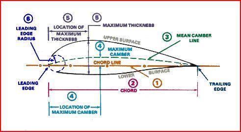
26 Airfoil Nomenclature 6
27 AIRFOIL NOMENCLATURE Mean Chamber Line: Set of points halfway between upper and lower surfaces Measured perpendicular to mean chamber line itself Leading Edge: Most forward point of mean chamber line 7
28 Trailing Edge: Most reward point of mean chamber line Chord Line: Straight line connecting the leading and trailing edges Chord, c: Distance along the chord line from leading to trailing edge Chamber: Maximum distance between mean chamber line and chord line Measured perpendicular to chord line 8
29 NACA FOUR-DIGIT SERIES NACA 415 First set of airfoils designed using this approach was NACA Four-Digit Series First digit specifies maximum camber in percentage of chord Second digit indicates position of maximum camber in tenths of chord Last two digits provide maximum thickness of airfoil in percentage of chord 9
30 AERODYNAMIC CHARETERISTICS Relative Wind: Direction of V We used subscript to indicate far upstream conditions Angle of Attack, a: Angle between relative wind (V ) and chord line 30
31 Total aerodynamic force, R, can be resolved into two force components Lift, L: Component of aerodynamic force perpendicular to relative wind Drag, D: Component of aerodynamic force parallel to relative wind 31
32 Center of Pressure The center of pressure is the point where the total sum of a pressure field acts on a body. In aerospace, this is the point on the airfoil (or wing) where the resultant vector (of lift and drag) acts. As the airfoil angle of attack changes, the pressure field changes. Due to this, the center of pressure changes with variation in the angle of attack. In the airplane's normal range of flight attitudes, if the angle of attack is increased, the center of pressure moves forward; and if decreased, it moves rearward 3
 also changes.")
33 The resultant (or the pressure forces) also cause a moment on the airfoil. As the angle of attack increases, the pitching moment at a point (for example, the center of gravity) also changes. However, the pitching moment remains constant at a particular point, which is called the aerodynamic center. 33
34 For symmetric airfoils in subsonic flight the aerodynamic center is located approximately 5% of the chord from the leading edge of the airfoil. This point is described as the quarter-chord point. Thus the aerodynamic center does not change with variation in angle of attack. Due to this, the aerodynamic center, rather than the center of pressure is used in the analysis of longitudinal stability. 34
35 Wing of infinite aspect ratio In aeronautics, the aspect ratio of a wing is the ratio of its span to its mean chord. It is equal to the square of the wingspan divided by the wing area. Thus, a long, narrow wing has a high aspect ratio, whereas a short, wide wing has a low aspect ratio. Aspect ratio and other features of the planform are often used to predict the aerodynamic efficiency of a wing because the lift-todrag ratio increases with aspect ratio, improving fuel economy in aircraft. 35
36 Flow velocity over top of airfoil is faster than over bottom surface Streamtube A senses upper portion of airfoil as an obstruction.streamtube A is squashed to smaller cross-sectional area Mass continuity AV=constant: IF A THEN V c l vsa 36
37 Lift coefficient (or lift) linear variation with angle of attack, Cambered airfoils have positive lift when a=0 Symmetric airfoils have zero lift when a=0 At high enough angle of attack, the performance of the airfoil rapidly degrades stall 37

38 The aspect ratio is ratio of the square of the wingspan b to the projected [ wing area s which is equal to the ratio of the wingspan b to the mean aerodynamic chord AR=b /s 38
39 HOW DOES AN AIRFOIL GENERATE LIFT? Lift due to imbalance of pressure distribution over top and bottom surfaces of airfoil (or wing) If pressure on top is lower than pressure on bottom surface, lift is generated Why is pressure lower on top surface? We can understand answer from basic physics: Continuity (Mass Conservation) Newton s nd law (Euler or Bernoulli Equation) 39

40 HOW DOES AN AIRFOIL GENERATE LIFT? Streamtube A is squashed most in nose region (ahead of maximum thickness) A B 40
41 Kutta condition The Kutta condition is a principle in steady-flow fluid dynamics especially aerodynamics that is applicable to solid bodies with sharp corners, such as the trailing edges of airfoils. It is named for German mathematician and aerodynamicist Martin Wilhelm Kutta. Kuethe and Schetzer state the Kutta condition as follows A body with a sharp trailing edge which is moving through a fluid will create about itself a circulation of sufficient strength to hold the rear stagnation point at the trailing edge. In fluid flow around a body with a sharp corner, the Kutta condition refers to the flow pattern in which fluid approaches the corner from both directions, meets at the corner, and then flows away from the body. None of the fluid flows around the corner, remaining attached to the body. 41
42 The Kutta condition is significant when using the Kutta Joukowski theorem to calculate the lift created by an airfoil with a cusped trailing edge. The value of circulation of the flow around the airfoil must be that value which would cause the Kutta condition to exist. 4
43 Thin airfoil theory Thin airfoil theory is a simple theory of airfoils that relates angle of attack to lift for incompressible, inviscid flows. It was devised by German-American mathematician Max Munk and further refined by British aerodynamicist Hermann Glauert and others in the 190s. The theory idealizes the flow around an airfoil as two-dimensional flow around a thin airfoil. It can be imagined as addressing an airfoil of zero thickness and infinite wingspan. Thin airfoil theory was particularly notable in its day because it provided a sound theoretical basis for the following important properties of airfoils in two-dimensional flow (1) on a symmetric airfoil, the center of pressure and aerodynamic center lies exactly one quarter of the chord behind the leading edge 43
44 () on a cambered airfoil, the aerodynamic center lies exactly one quarter of the chord behind the leading edge (3) the slope of the lift coefficient versus angle of attack line is units per radian As a consequence of the section lift coefficient of a symmetric airfoil of infinite wingspan is c l =Πα 44
45 Panel Methods Linear Strength Vortex Panel Method for a Two Element Airfoil Panel methods break up an airfoil geometry into "panels" and then solve for the flow around the panels. There are many different panel method variations and each variation has its own strengths and weaknesses. Panel methods have two key features that distinguish themselves from each other: the formulation of the boundary conditions and the type of singularity element used to describe the flow field around the airfoil. The Neumann boundary condition states the normal component of the flow near the airfoil must be zero. On the other hand, the Dirichlet boundary condition sets the flow potential to be constant at the boundary. The second key feature is the type of singularity element. A source, doublet or vortex element can be used, but the panel method presented here uses the vortex element since it can model both lift and pressure. 45
46 These are the various assumptions that go into developing potential flow panel methods: Inviscid Incompressible V = 0 Irrotational V = 0 Steady However, the incompressible flow assumption may be removed from the potential flow derivation leaving: Potential Flow (inviscid, irrotational, steady) ϕ = 0. 46
47 High lift airfoils 47
48 High lift devices. The most common high-lift device is the flap, a movable portion of the wing that can be lowered to produce extra lift. When a flap is lowered this re-shapes the wing section to give it more camber. Flaps are usually located on the trailing edge of a wing, while leading edge flaps are used occasionally. 48
49 UNIT-III Finite Wing Theory 49
50 A vortex line is a line whose tangent is everywhere parallel to the local vorticity vector. The vortex lines drawn through each point of a closed curve constitute the surface of a vortex tube. Finally, a vortex filament is a vortex tube whose cross-section is of infinitesimal dimensions. In fluid dynamics, circulation is the line integral around a closed curve of the velocity field. Circulation is normally denoted Γ 50
51 Kelvin and Helmhotz theorem According to the Kelvin circulation theorem, which is named after Lord Kelvin ( ), the circulation around any co-moving loop in an inviscid fluid is independent of time. The proof is as follows. The circulation around a given loop However, for a loop that is co-moving with the fluid, we have. Thus, 51
52 One corollary of the Kelvin circulation theorem is that the fluid particles that form the walls of a vortex tube at a given instance in time continue to form the walls of a vortex tube at all subsequent times. 5
53 Helmholtz s third theorem: In the absence of rotational external forces, a fluid that is initially irrotational remains irrotational. Helmholtz s theorems apply to inviscid flows. In observations of vortices in real fluids the strength of the vortices always decays gradually due to the dissipative effect of viscous forces. Alternative expressions of the three theorems are as follows: 1. The strength of a vortex tube does not vary with time.. Fluid elements lying on a vortex line at some instant continue to lie on that vortex line. More simply, vortex lines move with the fluid. Also vortex lines and tubes must appear as a closed loop, extend to infinity or start/end at solid boundaries. 3. Fluid elements initially free of vorticity remain free of vorticity. 53
54 Biot-Savart Law I db(r) The analogue of Coulomb s Law is the Biot-Savart Law r r-r Consider a current loop (I) O r dl For element dl there is an associated element field db db( r) Ι 4 o d x ( r r' ) 3 r r' db perpendicular to both dl and r - r Inverse square dependence on distance o /4p = 10-7 Hm -1 Integrate to get Biot-Savart Law B( r) o Ι d x ( r r' ) 3 4 r r' 54
55 Biot-Savart Law examples (1) Infinite straight conductor dl and r, r in the page db is into the page B forms concentric circles about the conductor dl r I z O r r - r a db B B( r) d x ( r r r' r r oi 4 r dz z r' ) / a oi B 4 z d x ( r r' ) 3 r r' r 3/ d r d d dz z x ( r r r' r r' sin nˆ sin cosa r 3/ r' ) 3 nˆ r r' sin nˆ 3 r r' r oi B nˆ r r r z r dz z 1/ 55 3/ nˆ
56 Biot-Savart Law examples () Axial field of circular loop dl Loop perpendicular to page, radius a dl out of page at top and r, r in the page On-axis element db is in the page, perpendicular to r - r, at q to axis. I r a r z r - r db n db z Magnitude of element db db cos a r -r' oi d x r -r' 3 4 r -r' oi d 4 r -r' a a z 1/ nˆ db Integrating around loop, only z-component of db contributes net result z oi d 4 r -r' cos 56


57 Rankine vortex The Rankine vortex is a type of vortex in a viscous fluid. It is named after its discoverer, William John Macquorn Rankine. A swirling flow in a viscous fluid can be characterized by a forced vortex in its central core, surrounded by a free vortex. In an inviscid fluid, on the other hand, a swirling flow consists entirely of the free vortex with a singularity at its center point instead of the forced vortex core. The tangential velocity of a Rankine vortex. Velocity distribution in a Rankine vortex. 57
58 Flow past finite wings 58
59 FINITE WING DESCRIPTION Finite Wing Case a geometric a effective a induced Induced Drag, D i Drag is measured in direction of incoming relative wind (that is the direction that the airplane is flying) Lift vector is tilted back Component of L acts in direction parallel to incoming relative wind results in a new type of drag 59

60 INDUCED DRAG Calculation of angle a i is not trivial (MAE 341) Value of a i depends on distribution of downwash along span of wing Downwash is governed by distribution of lift over span of wing 60
61 Special Case: Elliptical Lift Distribution (produced by elliptical wing) Lift/unit span varies elliptically along span This special case produces a uniform downwash Key Results: Elliptical Lift Distribution CL ai AR CL Di Lai L AR Di CL qs AR CL CD, i AR q CL S AR 61
62 The Elliptical Lift Distribution Solving the Fundamental Equation of Finite Wing Theory requires us to guess at a Γ (y) distribution and show it s a correct guess. (The same approach we used for the γ(x) distribution for thin airfoils.) As a first guess we consider an elliptic distribution: This distribution has circulation Γ0 at the root (y = 0) and Γ = 0 at the wingtips 6
63 Tapered Wings Taper ratio is defined as à Reduction of the amount of lift near the wing-tip. à Tip vortex is weaker à Induced drag is smaller Taper also reduces structural weight As the chord at the root is unchanged the maximum lift is not severely affected by taper If the taper is not too high, the stalling characteristics are acceptable, even without twist 63
64 Effect of wing taper on lift distribution Twisted wings 64
65 Wing twist (1) Wash-in: αtip > αroot Wash-out: αtip < αroot 65
66 Wings often have wash-out to reduce structural weight and improve stall characteristics. The point of initial stalling should be sufficiently inboard, around 0.4s from the wing root. This can be achieved with suitable twist. If the stall point is too far outboard, a little washout will bring it inboard. However, a washout of more than 5o results in an unacceptable increase in induced drag. 66
67 Effect of Wing Sweep In addition to reducing airfoil thickness, aircraft designers can also raise a wing s M crit by sweeping it either forward or aft. To understand how this works, consider the untapered, swept wing in Figure Sweeping the wing without changing its shape increases the effective chord length. Figure 4.34 shows why this is true. 1 m 1 m V LE = 45 o The Effect of Wing Sweep on Streamwise Thickness-to-Chord Ratio 67
68 Delta wing The delta wing is a wing shaped in the form of a triangle. It is named for its similarity in shape to the Greek uppercase letter delta (Δ). Canard delta Many modern fighter aircraft, such as the JAS 39 Gripen, the Eurofighter Typhoon and the Dassault Rafale use a combination of canards and a delta wing. Tailed delta adds a conventional tailplane (with horizontal tail surfaces), to improve handling. Common on Soviet types such as the Mikoyan-Gurevich MiG-1. Cropped delta tip is cut off. This helps avoid tip drag at high angles of attack. Used for example in all three Eurocanards (cropped, tailless delta combined with a canard). 68
69 primary and secondary vortex Swept wings that have platforms such as shown in Fig are called delta wings. dominant aspect of this flow is the two vortices that are formed along the highly swept leading edges, and that trail downstream over the top of the wing. This vortex pattern is created by the following mechanism. The pressure on the bottom surface of the wing is higher than the pressure on the top surface 69
70 Thus, the flow on the bottom surface in the vicinity of the leading edge tries to curl around the leading edge from the bottom to the top. If the leading edge is relatively sharp, the flow will separate along its entire length. This separated flow curls into a primary vortex above the wing just inboard of each leading edge. The stream surface which has separated at the leading edge loops above the wing and then reattaches along the primary attachment line. The primary vortex is contained within this loop. A secondary vortex is formed underneath the primary vortex, with its own separation line, and its own reattachment line. 70
71 Source Panel Method Steps to determine the solution: 1. Write down the velocities, ui, vi, in terms of contributions from all the singularities. This includes qi, g from each panel and the influence coefficients which are a function of the geometry only.. Find the algebraic equations defining the influence coefficients. To generate the system of algebraic equations: 3. Write down flow tangency conditions in terms of the velocities (N eqn s., N+1 unknowns). 4. Write down the Kutta condition equation to get the N+1 equation. 5. Solve the resulting linear algebraic system of equations for the qi, g.. 71
72 6. Given qi, g, write down the equations for uti, the tangential velocity at each panel control point. 7. Determine the pressure distribution from Bernoulli s equation using the tangential velocity on each panel. We now carry out each step in detail. The algebra gets tedious, but there s no problem in carrying it out. As we carry out the analysis for two dimensions, consider the additional algebra required for the general three dimensional case 7
73 Vortex panel Method PANEL is an exact implementation of the analysis given and is essentially the program given by Moran.6 Other panel method programs are available in the textbooks by Houghton and Carpenter,10 and Kuethe and Chow.11 Moran s program includes a subroutine to generate the ordinates for the NACA 4-digit and 5-digit airfoils (see Appendix A for a description of these airfoil sections). The main drawback is the requirement for a trailing edge thickness that s exactly zero. To accommodate this restriction, the ordinates generated internally have been altered slightly from the official ordinates. The extension of the program to handle arbitrary airfoils is an exercise. The freestream velocity in PANEL is assumed to be unity, since the inviscid solution in coefficient form is independent of scale. PANEL s node points are distributed employing the widely used cosine spacing function 73
74 The Classical Vortex Lattice Method There are many different vortex lattice schemes. In this section we describe the classical implementation. Knowing that vortices can represent lift from our airfoil analysis, and that one approach is to place the vortex and then satisfy the boundary condition using the 1/4-3/4 rule, we proceed as follows: 1. Divide the planform up into a lattice of quadrilateral panels, and put a horseshoe vortex on each panel.. Place the bound vortex of the horseshoe vortex on the 1/4 chord element line of each panel. 3. Place the control point on the 3/4 chord point of each panel at the midpoint in the spanwise direction (sometimes the lateral panel centroid location is used). 74
75 4. Assume a flat wake in the usual classical method. 5. Determine the strengths of each Gn required to satisfy the boundary conditions by solving a system of linear equations. The implementation is shown schematically 75
76 Note that the lift is on the bound vortices. To understand why, consider the vector statement of the Kutta-Joukowski Theorem, F = rv G. Assuming the freestream velocity is the primary contributor to the velocity, the trailing vortices are parallel to the velocity vector and hence the force on the trailing vortices are zero. More accurate methods find the wake deformation required to eliminate the force in the presence of the complete induced flowfield. 76
77 UNIT-IV Flow past non-lifting bodies and interference effects 77
78 INTRODUCTION Main function of the wing is to provide lift Modeled using lifting-line theory Uses method of singularities involving vortices Main function of the fuselage is to provide space for payload Design of a slender body which offers low drag Lift component of fuselage is relatively small Can be considered as a non-lifting body Modeled using method of singularities involving sources and doublets 78
79 ROAD MAP Study the aerodynamic characteristics of nonlifting bodies like fuselage, using the slender body theory Study the interference effects between wing and fuselage Briefly note the effect of propeller slipstream on wing/tail Briefly note a few aspects of flow over the whole airplane 79
80 FLOW PAST NON-LIFTING BODIES Main function of the fuselage is to provide space for passengers/cargo Design of a slender body which offers low drag Lift component of fuselage is relatively small Can be considered as a non-lifting body Analyze the flow over fuselage using the slender body theory Uses method of singularities involving sources and doublets 80
81 SLENDER BODY THEORY Flow past a slender body Assumptions for modeling as a slender body Low slenderness ratio, R(x)/l << 1 Small angle of attack, α << 1 Small ratio of body radius to length, dr(x)/dx << 1 81
82 SLENDER BODY THEORY Solve Laplace equation governing the flow past the slender body, represented in cylindrical coordinate system In this coordinate system, freestream velocity is 8
83 SLENDER BODY THEORY Solve Laplace equation governing the flow past the slender body, represented in cylindrical coordinate system In this coordinate system, freestream velocity is 83
84 SLENDER BODY THEORY Boundary condition for Laplace equation Solid wall condition Surface of the body: Q.n = 0 => Application of boundary condition gives:» = The above condition is superposition of: Longitudinal axisymmetric flow and Transverse flow 84
85 AXISYMMETRIC LONGITUDINAL FLOW Laplace equation: Corresponding boundary condition: Modeled using method of singularities involving sources: 85
86 AXISYMMETRIC LONGITUDINAL FLOW Using potential theory, solution for axisymmetric longitudinal flow: 86
87 TRANSVERSE FLOW Laplace equation: Corresponding boundary condition: Modeled using method of singularities involving doublets: 87
88 TRANSVERSE FLOW Using potential theory, solution for transverse flow: 88
89 COMPLETE SOLUTION FOR FLOW PAST SLENDER BODY (LIKE FUSELAGE) Adding up the potentials for longitudinal and transverse flows, we get: Conclusions from the above expressions: The side force distribution is zero and therefore the side force is also zero. The normal force distribution is proportional to the AOA and the rate of change of cross-sectional area. The normal force distribution can become zero if the body s ends are pointed. The axial force can also become zero if the body s ends are pointed For pointed slender bodies, there is no lift and pressure drag, but there is an aerodynamic pitching moment. 89
90 WING-BODY INTERFERENCE Interference effects can be of the same order of magnitude as the aerodynamic effects of the individual parts Wing-fuselage interference Wing affects flow field around fuselage Fuselage affects flow field around wing Two cases to be discussed: Symmetric flow around the wing-fuselage system Asymmetric flow around the wing-fuselage system 90
91 SYMMETRIC FLOW: EFFECT OF WING ON FUSELAGE Along the fuselage axis: Additive velocities normal to the fuselage axis are induced by the wing Near wing-fuselage penetration, the flow is parallel to the wing chord 91
92 SYMMETRIC FLOW: EFFECT OF WING ON FUSELAGE Fuselage is therefore in a curved flow Angle-of-attack distribution α(x) varies along the fuselage axis This induced AOA distribution, shows that fuselage is subjected to an additive nose-up pitching moment 9
93 SYMMETRIC FLOW: EFFECT OF FUSELAGE ON WING Component of the incident flow velocity normal to the fuselage axis U.sinα Uα, generates additive upwash velocities in the vicinity of the fuselage Induced velocities normal to the plane of the wing with an additive symmetric angle-of-attack distribution over the wing span (twist angle) 93
94 ASYMMETRIC FLOW: EFFECT OF WING ON FUSELAGE Flow field of a wing-fuselage system at subsonic velocity in asymmetric, incident flow (angle of sideslip 0) : Flow fields divided into: Incident flow parallel to the plane of symmetry, of velocity U.cosβ U Cross flow normal to the plane of symmetry, of velocity U.sinβ Uβ 94
95 CROSS FLOW ON WING-FUSELAGE SYSTEM Lift distributions over the wing span generated by the cross flow have reversed signs for high-wing and low-wing airplanes. The rolling moment due to sideslip: Positive for the high-wing airplane Zero for the mid-wing airplane Negative for the low-wing airplane 95
96 CROSS FLOW ON WING-FUSELAGE SYSTEM 96
97 EFFECTS OF PROPELLER STREAM ON THE WING/TAIL DOWNSTREAM Experimental studies showed that when the wing/tail was under the effect of the slipstream (jet) from a propeller whose axis was fixed in the direction of the undisturbed wind, the rotation and the dynamic pressure changes in the jet resulted in a nonsymmetrical variation in the lift. Study of the downwash relations led to the result that the two portions into which the jet is divided by the wing/tail did not again reunite behind the wing/tail but that each portion experienced a lateral deviation in the direction of the jet rotation. 97
98 FLOW OVER WHOLE AIRPLANE Aircraft lift coefficient Complete aircraft usually generates more lift than its wing alone C Lα (whole aircraft) = C Lα (wing) + C Lα (horizontal tail) Aircraft drag coefficient where: C DOL = zero-lift drag coefficient, parasite drag coefficient e = Oswald (aircraft) efficiency factor AR = Aspect ratio of the wing 98
99 UNIT-V Boundary Layer Theory 99
100 boundary layer In physics and fluid mechanics, a boundary layer is an important concept and refers to the layer of fluid in the immediate vicinity of a bounding surface where the effects of viscosity are significant. In the Earth's atmosphere, the atmospheric boundary layer is the air layer near the ground affected by diurnal heat, moisture or momentum transfer to or from the surface. On an aircraft wing the boundary layer is the part of the flow close to the wing, where viscous forces distort the surrounding nonviscous flow. 100
101 Boundary Layer and separation Flow accelerates Constant flow Flow decelerates P 0, favorable x pressuregradient P 0, no gradient x Separation point P 0, adverse x pressure gradient Flow reversal free shear layer highly unstable 101
102 Flow separation occurs when: Flow separation the velocity at the wall is zero or negative and an inflection point exists in the velocity profile, and a positive or adverse pressure gradient occurs in the direction of flow. 10
")
103 Laminar flow Also known as streamline flow Occurs when the fluid flows in parallel layers, with no disruption between the layers The opposite of turbulent flow (rough) 103
104 The turbulent boundary layer In turbulent flow, the boundary layer is defined as the thin region on the surface of a body in which viscous effects are important. The boundary layer allows the fluid to transition from the free stream velocity U to a velocity of zero at the wall. The velocity component normal to the surface is much smaller than the velocity parallel to the surface: v << u. The gradients of the flow across the layer are much greater than the gradients in the flow direction. The boundary layer thickness is defined as the distance away from the surface where the velocity reaches 99% of the freestream velocity. y, where u 0.99 U 104
105 The turbulent boundary layer 105
106 BOUNDARY LAYER ON A FLAT PLATE Consider the following scenario. 1. A steady potential flow has constant velocity U in the x direction.. An infinitely thin flat plate is placed into this flow so that the plate is parallel to the potential flow (0 angle of incidence). Viscosity should retard the flow, thus creating a boundary layer on either side of the plate. Here only the boundary layer on one side of the plate is considered. The flow is assumed to be laminar. Boundary layer theory allows us to calculate the drag on the plate! U U y x u plate 106
107 A steady, rectilinear potential flow in the x direction is described by the relations Ux, u x U According to Bernoulli s equation for potential flows, the dynamic pressure of the potential flow p pd is related to the velocity field as p pd 1 (u Between the above two equations, then, for this flow v ), v const 0 y p pd x p pd y 0 107
108 BOUNDARY LAYER EQUATIONS FOR A FLAT PLATE For the case of a steady, laminar boundary layer on a flat plate at 0 angle of incidence, with vanishing imposed pressure gradient, the boundary layer equations and boundary conditions become (see Slide 15 of BoundaryLayerApprox.ppt with dp pds /dx = 0) u u v x y u x 0 1 dp dx u y pds u v y u x u x u v y 0 u y u v y u y0 0, v y0 0, u y U Tangential and normal velocities vanish at boundary: tangential velocity = free stream velocity far from plate 108
109 displacement thickness The displacement thickness, δ * or δ 1 is the distance by which a surface would have to be moved in the direction perpendicular to its normal vector away from the reference plane in an inviscid fluid stream of velocity to give the same flow rate as occurs between the surface and the reference plane in a real fluid. In practical aerodynamics, the displacement thickness essentially modifies the shape of a body immersed in a fluid to allow an inviscid solution. It is commonly used in aerodynamics to overcome the difficulty inherent in the fact that the fluid velocity in the boundary layer approaches asymptotically to the free stream value as distance from the wall increases at any given location. 109
110 The definition of the displacement thickness for compressible flow is based on mass flow rate. 110
111 momentum thickness The momentum thickness, θ or δ, is the distance by which a surface would have to be moved parallel to itself towards the reference plane in an inviscid fluid stream of velocity to give the same total momentum as exists between the surface and the reference plane in a real fluid. The definition of the momentum thickness for compressible flow is based on mass flow rate: 111
112 Energy thickness The energy thickness is the distance by which a surface would have to be moved parallel to itself towards the reference plane in an inviscid fluid stream of velocity to give the same total kinetic energy as exists between the surface and the reference plane in a real fluid. The definition of the energy thickness for compressible flow is based on mass flow rate 11
113 Effect of curvature on boundary layer The effect of transverse surface curvature on the turbulent boundary layer is reviewed by recourse to experiments on axial flow along a circular cylinder. Three flow regimes are identified depending on values of the two controlling parameters, namely, the Reynolds number and the ratio of the boundary layer thickness to cylinder radius. The boundary layer flow resembles a wake when both parameters are large. As expected, the effect of curvature is small when the Reynolds number is large and the boundary layer is thin. When the boundary layer is thick and the Reynolds number is small, which is typical of laboratory investigations, the effect of transverse curvature is felt throughout the boundary layer with evidence for relaminarization at the low Reynolds numbers. This review describes the experimental evidence and points out gaps 113 that remain
114 Temperature boundary layer IfT s >T f, the fluid temperature approaches asymptotically and the temperature profile at a distance x However, a thermal boundary may be defined (similar to velocity boundary) as the distance from the surface to the point where the temperature is within 1% of the free stream fluid temperature (T f ). 114
115 Outside the thermal boundary layer the fluid is assumed to be a heat sink at a uniform temperature oft f. The thermal boundary layer is generally not coincident with the velocity boundary layer, although it is certainly dependant on it. That is, the velocity, boundary layer thickness, the variation of velocity, whether the flow is laminar or turbulent etc are all the factors which determine the temperature variation in the thermal boundary layer. 115
INSTITUTE OF AERONAUTICAL ENGINEERING (Autonomous) Dundigal, Hyderabad
 Dundigal, Hyderabad") INSTITUTE OF AERONAUTICAL ENGINEERING (Autonomous) Dundigal, Hyderabad - 500 043 AERONAUTICAL ENGINEERING TUTORIAL QUESTION BANK Course Name : LOW SPEED AERODYNAMICS Course Code : AAE004 Regulation : IARE
INSTITUTE OF AERONAUTICAL ENGINEERING (Autonomous) Dundigal, Hyderabad - 500 043 AERONAUTICAL ENGINEERING TUTORIAL QUESTION BANK Course Name : LOW SPEED AERODYNAMICS Course Code : AAE004 Regulation : IARE
1. Fluid Dynamics Around Airfoils
 1. Fluid Dynamics Around Airfoils Two-dimensional flow around a streamlined shape Foces on an airfoil Distribution of pressue coefficient over an airfoil The variation of the lift coefficient with the
Given a stream function for a cylinder in a uniform flow with circulation: a) Sketch the flow pattern in terms of streamlines.
 Sketch the flow pattern in terms of streamlines.") Question Given a stream function for a cylinder in a uniform flow with circulation: R Γ r ψ = U r sinθ + ln r π R a) Sketch the flow pattern in terms of streamlines. b) Derive an expression for the angular
Question Given a stream function for a cylinder in a uniform flow with circulation: R Γ r ψ = U r sinθ + ln r π R a) Sketch the flow pattern in terms of streamlines. b) Derive an expression for the angular
Lifting Airfoils in Incompressible Irrotational Flow. AA210b Lecture 3 January 13, AA210b - Fundamentals of Compressible Flow II 1
 Lifting Airfoils in Incompressible Irrotational Flow AA21b Lecture 3 January 13, 28 AA21b - Fundamentals of Compressible Flow II 1 Governing Equations For an incompressible fluid, the continuity equation
Given the water behaves as shown above, which direction will the cylinder rotate?
 water stream fixed but free to rotate Given the water behaves as shown above, which direction will the cylinder rotate? ) Clockwise 2) Counter-clockwise 3) Not enough information F y U 0 U F x V=0 V=0
Lecture-4. Flow Past Immersed Bodies
 Lecture-4 Flow Past Immersed Bodies Learning objectives After completing this lecture, you should be able to: Identify and discuss the features of external flow Explain the fundamental characteristics
Department of Mechanical Engineering
 Department of Mechanical Engineering AMEE401 / AUTO400 Aerodynamics Instructor: Marios M. Fyrillas Email: eng.fm@fit.ac.cy HOMEWORK ASSIGNMENT #2 QUESTION 1 Clearly there are two mechanisms responsible
High Speed Aerodynamics. Copyright 2009 Narayanan Komerath
 Welcome to High Speed Aerodynamics 1 Lift, drag and pitching moment? Linearized Potential Flow Transformations Compressible Boundary Layer WHAT IS HIGH SPEED AERODYNAMICS? Airfoil section? Thin airfoil
Detailed Outline, M E 521: Foundations of Fluid Mechanics I
 Detailed Outline, M E 521: Foundations of Fluid Mechanics I I. Introduction and Review A. Notation 1. Vectors 2. Second-order tensors 3. Volume vs. velocity 4. Del operator B. Chapter 1: Review of Basic
PEMP ACD2505. M.S. Ramaiah School of Advanced Studies, Bengaluru
 Two-Dimensional Potential Flow Session delivered by: Prof. M. D. Deshpande 1 Session Objectives -- At the end of this session the delegate would have understood PEMP The potential theory and its application
Aerodynamics. High-Lift Devices
 High-Lift Devices Devices to increase the lift coefficient by geometry changes (camber and/or chord) and/or boundary-layer control (avoid flow separation - Flaps, trailing edge devices - Slats, leading
SPC Aerodynamics Course Assignment Due Date Monday 28 May 2018 at 11:30
 SPC 307 - Aerodynamics Course Assignment Due Date Monday 28 May 2018 at 11:30 1. The maximum velocity at which an aircraft can cruise occurs when the thrust available with the engines operating with the
Fundamentals of Fluid Dynamics: Ideal Flow Theory & Basic Aerodynamics
 Fundamentals of Fluid Dynamics: Ideal Flow Theory & Basic Aerodynamics Introductory Course on Multiphysics Modelling TOMASZ G. ZIELIŃSKI (after: D.J. ACHESON s Elementary Fluid Dynamics ) bluebox.ippt.pan.pl/
Copyright 2007 N. Komerath. Other rights may be specified with individual items. All rights reserved.
 Low Speed Aerodynamics Notes 5: Potential ti Flow Method Objective: Get a method to describe flow velocity fields and relate them to surface shapes consistently. Strategy: Describe the flow field as the
Introduction to Aerospace Engineering
 4. Basic Fluid (Aero) Dynamics Introduction to Aerospace Engineering Here, we will try and look at a few basic ideas from the complicated field of fluid dynamics. The general area includes studies of incompressible,
Syllabus for AE3610, Aerodynamics I
 Syllabus for AE3610, Aerodynamics I Current Catalog Data: AE 3610 Aerodynamics I Credit: 4 hours A study of incompressible aerodynamics of flight vehicles with emphasis on combined application of theory
Flight Vehicle Terminology
 Flight Vehicle Terminology 1.0 Axes Systems There are 3 axes systems which can be used in Aeronautics, Aerodynamics & Flight Mechanics: Ground Axes G(x 0, y 0, z 0 ) Body Axes G(x, y, z) Aerodynamic Axes
 UNIT IV BOUNDARY LAYER AND FLOW THROUGH PIPES Definition of boundary layer Thickness and classification Displacement and momentum thickness Development of laminar and turbulent flows in circular pipes
Wings and Bodies in Compressible Flows
 Wings and Bodies in Compressible Flows Prandtl-Glauert-Goethert Transformation Potential equation: 1 If we choose and Laplace eqn. The transformation has stretched the x co-ordinate by 2 Values of at corresponding
Inviscid & Incompressible flow
 < 3.1. Introduction and Road Map > Basic aspects of inviscid, incompressible flow Bernoulli s Equation Laplaces s Equation Some Elementary flows Some simple applications 1.Venturi 2. Low-speed wind tunnel
Airfoils and Wings. Eugene M. Cliff
 Airfoils and Wings Eugene M. Cliff 1 Introduction The primary purpose of these notes is to supplement the text material related to aerodynamic forces. We are mainly interested in the forces on wings and
FUNDAMENTALS OF AERODYNAMICS
 *A \ FUNDAMENTALS OF AERODYNAMICS Second Edition John D. Anderson, Jr. Professor of Aerospace Engineering University of Maryland H ' McGraw-Hill, Inc. New York St. Louis San Francisco Auckland Bogota Caracas
Fundamentals of Aerodynamits
 Fundamentals of Aerodynamits Fifth Edition in SI Units John D. Anderson, Jr. Curator of Aerodynamics National Air and Space Museum Smithsonian Institution and Professor Emeritus University of Maryland
Fundamentals of Aerodynamics
 Fundamentals of Aerodynamics Fourth Edition John D. Anderson, Jr. Curator of Aerodynamics National Air and Space Museum Smithsonian Institution and Professor Emeritus University of Maryland Me Graw Hill
Fluid Mechanics Prof. T. I. Eldho Department of Civil Engineering Indian Institute of Technology, Bombay
 Fluid Mechanics Prof. T. I. Eldho Department of Civil Engineering Indian Institute of Technology, Bombay Lecture No. # 35 Boundary Layer Theory and Applications Welcome back to the video course on fluid
General Solution of the Incompressible, Potential Flow Equations
 CHAPTER 3 General Solution of the Incompressible, Potential Flow Equations Developing the basic methodology for obtaining the elementary solutions to potential flow problem. Linear nature of the potential
BLUFF-BODY AERODYNAMICS
 International Advanced School on WIND-EXCITED AND AEROELASTIC VIBRATIONS OF STRUCTURES Genoa, Italy, June 12-16, 2000 BLUFF-BODY AERODYNAMICS Lecture Notes by Guido Buresti Department of Aerospace Engineering
1. Introduction, tensors, kinematics
 1. Introduction, tensors, kinematics Content: Introduction to fluids, Cartesian tensors, vector algebra using tensor notation, operators in tensor form, Eulerian and Lagrangian description of scalar and
Applied Fluid Mechanics
 Applied Fluid Mechanics 1. The Nature of Fluid and the Study of Fluid Mechanics 2. Viscosity of Fluid 3. Pressure Measurement 4. Forces Due to Static Fluid 5. Buoyancy and Stability 6. Flow of Fluid and
Investigation potential flow about swept back wing using panel method
 INTERNATIONAL JOURNAL OF ENERGY AND ENVIRONMENT Volume 7, Issue 4, 2016 pp.317-326 Journal homepage: www.ijee.ieefoundation.org Investigation potential flow about swept back wing using panel method Wakkas
The E80 Wind Tunnel Experiment the experience will blow you away. by Professor Duron Spring 2012
 The E80 Wind Tunnel Experiment the experience will blow you away by Professor Duron Spring 2012 Objectives To familiarize the student with the basic operation and instrumentation of the HMC wind tunnel
Lecture 7 Boundary Layer
 SPC 307 Introduction to Aerodynamics Lecture 7 Boundary Layer April 9, 2017 Sep. 18, 2016 1 Character of the steady, viscous flow past a flat plate parallel to the upstream velocity Inertia force = ma
Drag (2) Induced Drag Friction Drag Form Drag Wave Drag
 Induced Drag Friction Drag Form Drag Wave Drag") Drag () Induced Drag Friction Drag Form Drag Wave Drag Outline Nomenclature and Concepts Farfield Drag Analysis Induced Drag Multiple Lifting Surfaces Zero Lift Drag :Friction and Form Drag Supersonic
Drag () Induced Drag Friction Drag Form Drag Wave Drag Outline Nomenclature and Concepts Farfield Drag Analysis Induced Drag Multiple Lifting Surfaces Zero Lift Drag :Friction and Form Drag Supersonic
Fluid Dynamics: Theory, Computation, and Numerical Simulation Second Edition
 Fluid Dynamics: Theory, Computation, and Numerical Simulation Second Edition C. Pozrikidis m Springer Contents Preface v 1 Introduction to Kinematics 1 1.1 Fluids and solids 1 1.2 Fluid parcels and flow
Numerical Simulation of Unsteady Aerodynamic Coefficients for Wing Moving Near Ground
 ISSN -6 International Journal of Advances in Computer Science and Technology (IJACST), Vol., No., Pages : -7 Special Issue of ICCEeT - Held during -5 November, Dubai Numerical Simulation of Unsteady Aerodynamic
AERODYNAMICS STUDY NOTES UNIT I REVIEW OF BASIC FLUID MECHANICS. Continuity, Momentum and Energy Equations. Applications of Bernouli s theorem
 AERODYNAMICS STUDY NOTES UNIT I REVIEW OF BASIC FLUID MECHANICS. Continuity, Momentum and Energy Equations. Applications of Bernouli s theorem UNIT II TWO DIMENSIONAL FLOWS Complex Potential, Point Source
Aerodynamics. Lecture 1: Introduction - Equations of Motion G. Dimitriadis
 Aerodynamics Lecture 1: Introduction - Equations of Motion G. Dimitriadis Definition Aerodynamics is the science that analyses the flow of air around solid bodies The basis of aerodynamics is fluid dynamics
Active Control of Separated Cascade Flow
 Chapter 5 Active Control of Separated Cascade Flow In this chapter, the possibility of active control using a synthetic jet applied to an unconventional axial stator-rotor arrangement is investigated.
PEMP ACD2505. Finite Wing Theory. M.S. Ramaiah School of Advanced Studies, Bengaluru
 Finite Wing Theory Session delivered by: Prof. M. D. Deshpande 1 Session Objectives -- At the end of this session the delegate would have understood The finite wing theory Lifting line theory Elliptic
Definitions. Temperature: Property of the atmosphere (τ). Function of altitude. Pressure: Property of the atmosphere (p). Function of altitude.
. Function of altitude. Pressure: Property of the atmosphere (p). Function of altitude.") Definitions Chapter 3 Standard atmosphere: A model of the atmosphere based on the aerostatic equation, the perfect gas law, an assumed temperature distribution, and standard sea level conditions. Temperature:
Definitions Chapter 3 Standard atmosphere: A model of the atmosphere based on the aerostatic equation, the perfect gas law, an assumed temperature distribution, and standard sea level conditions. Temperature:
Aerodynamics. Basic Aerodynamics. Continuity equation (mass conserved) Some thermodynamics. Energy equation (energy conserved)
 Some thermodynamics. Energy equation (energy conserved)") Flow with no friction (inviscid) Aerodynamics Basic Aerodynamics Continuity equation (mass conserved) Flow with friction (viscous) Momentum equation (F = ma) 1. Euler s equation 2. Bernoulli s equation
Flow with no friction (inviscid) Aerodynamics Basic Aerodynamics Continuity equation (mass conserved) Flow with friction (viscous) Momentum equation (F = ma) 1. Euler s equation 2. Bernoulli s equation
FLUID MECHANICS. Chapter 9 Flow over Immersed Bodies
 FLUID MECHANICS Chapter 9 Flow over Immersed Bodies CHAP 9. FLOW OVER IMMERSED BODIES CONTENTS 9.1 General External Flow Characteristics 9.3 Drag 9.4 Lift 9.1 General External Flow Characteristics 9.1.1
Mechanics of Flight. Warren F. Phillips. John Wiley & Sons, Inc. Professor Mechanical and Aerospace Engineering Utah State University WILEY
 Mechanics of Flight Warren F. Phillips Professor Mechanical and Aerospace Engineering Utah State University WILEY John Wiley & Sons, Inc. CONTENTS Preface Acknowledgments xi xiii 1. Overview of Aerodynamics
ANALYSIS OF HORIZONTAL AXIS WIND TURBINES WITH LIFTING LINE THEORY
 ANALYSIS OF HORIZONTAL AXIS WIND TURBINES WITH LIFTING LINE THEORY Daniela Brito Melo daniela.brito.melo@tecnico.ulisboa.pt Instituto Superior Técnico, Universidade de Lisboa, Portugal December, 2016 ABSTRACT
V (r,t) = i ˆ u( x, y,z,t) + ˆ j v( x, y,z,t) + k ˆ w( x, y, z,t)
 = i ˆ u( x, y,z,t) + ˆ j v( x, y,z,t) + k ˆ w( x, y, z,t)") IV. DIFFERENTIAL RELATIONS FOR A FLUID PARTICLE This chapter presents the development and application of the basic differential equations of fluid motion. Simplifications in the general equations and common
IV. DIFFERENTIAL RELATIONS FOR A FLUID PARTICLE This chapter presents the development and application of the basic differential equations of fluid motion. Simplifications in the general equations and common
Detailed Outline, M E 320 Fluid Flow, Spring Semester 2015
 Detailed Outline, M E 320 Fluid Flow, Spring Semester 2015 I. Introduction (Chapters 1 and 2) A. What is Fluid Mechanics? 1. What is a fluid? 2. What is mechanics? B. Classification of Fluid Flows 1. Viscous
PEMP ACD2501. M.S. Ramaiah School of Advanced Studies, Bengaluru
 Aircraft Aerodynamics Session delivered by: Mr. Ramjan Pathan 1 Session Objectives At the end of this session students would have understood Basics of Fluid Mechanics Definition of fluid, Fluid flow applications
Some Basic Plane Potential Flows
 Some Basic Plane Potential Flows Uniform Stream in the x Direction A uniform stream V = iu, as in the Fig. (Solid lines are streamlines and dashed lines are potential lines), possesses both a stream function
Contents. I Introduction 1. Preface. xiii
 Contents Preface xiii I Introduction 1 1 Continuous matter 3 1.1 Molecules................................ 4 1.2 The continuum approximation.................... 6 1.3 Newtonian mechanics.........................
Masters in Mechanical Engineering Aerodynamics 1 st Semester 2015/16
 Masters in Mechanical Engineering Aerodynamics st Semester 05/6 Exam st season, 8 January 06 Name : Time : 8:30 Number: Duration : 3 hours st Part : No textbooks/notes allowed nd Part : Textbooks allowed
Mestrado Integrado em Engenharia Mecânica Aerodynamics 1 st Semester 2012/13
 Mestrado Integrado em Engenharia Mecânica Aerodynamics 1 st Semester 212/13 Exam 2ª época, 2 February 213 Name : Time : 8: Number: Duration : 3 hours 1 st Part : No textbooks/notes allowed 2 nd Part :
Department of Energy Sciences, LTH
 Department of Energy Sciences, LTH MMV11 Fluid Mechanics LABORATION 1 Flow Around Bodies OBJECTIVES (1) To understand how body shape and surface finish influence the flow-related forces () To understand
AE301 Aerodynamics I UNIT B: Theory of Aerodynamics
 AE301 Aerodynamics I UNIT B: Theory of Aerodynamics ROAD MAP... B-1: Mathematics for Aerodynamics B-: Flow Field Representations B-3: Potential Flow Analysis B-4: Applications of Potential Flow Analysis
Fluid Dynamics Problems M.Sc Mathematics-Second Semester Dr. Dinesh Khattar-K.M.College
 Fluid Dynamics Problems M.Sc Mathematics-Second Semester Dr. Dinesh Khattar-K.M.College 1. (Example, p.74, Chorlton) At the point in an incompressible fluid having spherical polar coordinates,,, the velocity
Incompressible Flow Over Airfoils
 Chapter 7 Incompressible Flow Over Airfoils Aerodynamics of wings: -D sectional characteristics of the airfoil; Finite wing characteristics (How to relate -D characteristics to 3-D characteristics) How
List of symbols. Latin symbols. Symbol Property Unit
 Abstract Aircraft icing continues to be a threat for modern day aircraft. Icing occurs when supercooled large droplets (SLD s) impinge on the body of the aircraft. These droplets can bounce off, freeze
Thin airfoil theory. Chapter Compressible potential flow The full potential equation
 hapter 4 Thin airfoil theory 4. ompressible potential flow 4.. The full potential equation In compressible flow, both the lift and drag of a thin airfoil can be determined to a reasonable level of accuracy
Aerodynamic Rotor Model for Unsteady Flow and Wake Impact
 Aerodynamic Rotor Model for Unsteady Flow and Wake Impact N. Bampalas, J. M. R. Graham Department of Aeronautics, Imperial College London, Prince Consort Road, London, SW7 2AZ June 28 1 (Steady Kutta condition)
To highlight the change in drag with lift: Drag = Zero-Lift Drag + Lift-Dependent Drag + Compressibility Drag
 Drag Drag Bookkeeping Drag may be divided into components in several ways: To highlight the change in drag with lift: Drag = Zero-Lift Drag + Lift-Dependent Drag + Compressibility Drag To emphasize the
An Internet Book on Fluid Dynamics. Joukowski Airfoils
 An Internet Book on Fluid Dynamics Joukowski Airfoils One of the more important potential flow results obtained using conformal mapping are the solutions of the potential flows past a family of airfoil
Chapter 6: Incompressible Inviscid Flow
 Chapter 6: Incompressible Inviscid Flow 6-1 Introduction 6-2 Nondimensionalization of the NSE 6-3 Creeping Flow 6-4 Inviscid Regions of Flow 6-5 Irrotational Flow Approximation 6-6 Elementary Planar Irrotational
Numerical Investigation of the Fluid Flow around and Past a Circular Cylinder by Ansys Simulation
 , pp.49-58 http://dx.doi.org/10.1457/ijast.016.9.06 Numerical Investigation of the Fluid Flow around and Past a Circular Cylinder by Ansys Simulation Mojtaba Daneshi Department of Mechanical Engineering,
AE 2020: Low Speed Aerodynamics. I. Introductory Remarks Read chapter 1 of Fundamentals of Aerodynamics by John D. Anderson
 AE 2020: Low Speed Aerodynamics I. Introductory Remarks Read chapter 1 of Fundamentals of Aerodynamics by John D. Anderson Text Book Anderson, Fundamentals of Aerodynamics, 4th Edition, McGraw-Hill, Inc.
Homework Two. Abstract: Liu. Solutions for Homework Problems Two: (50 points total). Collected by Junyu
. Collected by Junyu") Homework Two Abstract: Liu. Solutions for Homework Problems Two: (50 points total). Collected by Junyu Contents 1 BT Problem 13.15 (8 points) (by Nick Hunter-Jones) 1 2 BT Problem 14.2 (12 points: 3+3+3+3)
Homework Two Abstract: Liu. Solutions for Homework Problems Two: (50 points total). Collected by Junyu Contents 1 BT Problem 13.15 (8 points) (by Nick Hunter-Jones) 1 2 BT Problem 14.2 (12 points: 3+3+3+3)
Fluid Mechanics II 3 credit hour. External flows. Course teacher Dr. M. Mahbubur Razzaque Professor Department of Mechanical Engineering BUET 1
 COURSE NUMBER: ME 323 Fluid Mechanics II 3 credit hour External flows Course teacher Dr. M. Mahbubur Razzaque Professor Department of Mechanical Engineering BUET 1 External flows The study of external
1. Introduction - Tutorials
 1. Introduction - Tutorials 1.1 Physical properties of fluids Give the following fluid and physical properties(at 20 Celsius and standard pressure) with a 4-digit accuracy. Air density : Water density
Continuity Equation for Compressible Flow
 Continuity Equation for Compressible Flow Velocity potential irrotational steady compressible Momentum (Euler) Equation for Compressible Flow Euler's equation isentropic velocity potential equation for
6.1 Momentum Equation for Frictionless Flow: Euler s Equation The equations of motion for frictionless flow, called Euler s
 Chapter 6 INCOMPRESSIBLE INVISCID FLOW All real fluids possess viscosity. However in many flow cases it is reasonable to neglect the effects of viscosity. It is useful to investigate the dynamics of an
Math 575-Lecture Failure of ideal fluid; Vanishing viscosity. 1.1 Drawbacks of ideal fluids. 1.2 vanishing viscosity
 Math 575-Lecture 12 In this lecture, we investigate why the ideal fluid is not suitable sometimes; try to explain why the negative circulation appears in the airfoil and introduce the vortical wake to
COURSE ON VEHICLE AERODYNAMICS Prof. Tamás Lajos University of Rome La Sapienza 1999
 COURSE ON VEHICLE AERODYNAMICS Prof. Tamás Lajos University of Rome La Sapienza 1999 1. Introduction Subject of the course: basics of vehicle aerodynamics ground vehicle aerodynamics examples in car, bus,
Boundary-Layer Theory
 Hermann Schlichting Klaus Gersten Boundary-Layer Theory With contributions from Egon Krause and Herbert Oertel Jr. Translated by Katherine Mayes 8th Revised and Enlarged Edition With 287 Figures and 22
Random Problems. Problem 1 (30 pts)
") Random Problems Problem (3 pts) An untwisted wing with an elliptical planform has an aspect ratio of 6 and a span of m. The wing loading (defined as the lift per unit area of the wing) is 9N/m when flying
Random Problems Problem (3 pts) An untwisted wing with an elliptical planform has an aspect ratio of 6 and a span of m. The wing loading (defined as the lift per unit area of the wing) is 9N/m when flying
Steady waves in compressible flow
 Chapter Steady waves in compressible flow. Oblique shock waves Figure. shows an oblique shock wave produced when a supersonic flow is deflected by an angle. Figure.: Flow geometry near a plane oblique
ACD2503 Aircraft Aerodynamics
 ACD2503 Aircraft Aerodynamics Session delivered by: Prof. M. D. Deshpande 1 Aims and Summary PEMP It is intended dto prepare students for participation i i in the design process of an aircraft and its
Fluid Dynamics Exercises and questions for the course
 Fluid Dynamics Exercises and questions for the course January 15, 2014 A two dimensional flow field characterised by the following velocity components in polar coordinates is called a free vortex: u r
THE EFFECT OF INTERNAL ACOUSTIC EXCITATION ON THE AERODYNAMIC CHARACTERISTICS OF AIRFOIL AT HIGH ANGLE OF ATTACKE
 Vol.1, Issue.2, pp-371-384 ISSN: 2249-6645 THE EFFECT OF INTERNAL ACOUSTIC EXCITATION ON THE AERODYNAMIC CHARACTERISTICS OF AIRFOIL AT HIGH ANGLE OF ATTACKE Dr. Mohammed W. Khadim Mechanical Engineering
Chapter 3 Bernoulli Equation
 1 Bernoulli Equation 3.1 Flow Patterns: Streamlines, Pathlines, Streaklines 1) A streamline, is a line that is everywhere tangent to the velocity vector at a given instant. Examples of streamlines around
Improved Method for Prediction of Attainable Wing Leading-Edge Thrust
 NASA Technical Paper 3557 Improved Method for Prediction of Attainable Wing Leading-Edge Thrust Harry W. Carlson Lockheed Engineering & Sciences Company Hampton, Virginia Marcus O. McElroy and Wendy B.
Chapter 9 Flow over Immersed Bodies
 57:00 Mechanics of Fluids and Transport Processes Chapter 9 Professor Fred Stern Fall 009 1 Chapter 9 Flow over Immersed Bodies Fluid flows are broadly categorized: 1. Internal flows such as ducts/pipes,
Iran University of Science & Technology School of Mechanical Engineering Advance Fluid Mechanics
 1. Consider a sphere of radius R immersed in a uniform stream U0, as shown in 3 R Fig.1. The fluid velocity along streamline AB is given by V ui U i x 1. 0 3 Find (a) the position of maximum fluid acceleration
A Numerical Blade Element Approach to Estimating Propeller Flowfields
 Utah State University DigitalCommons@USU Mechanical and Aerospace Engineering Faculty Publications Mechanical and Aerospace Engineering 1-8-27 A Numerical Blade Element Approach to Estimating Propeller
NPTEL Quiz Hydraulics
 Introduction NPTEL Quiz Hydraulics 1. An ideal fluid is a. One which obeys Newton s law of viscosity b. Frictionless and incompressible c. Very viscous d. Frictionless and compressible 2. The unit of kinematic
Fluid Mechanics Prof. T.I. Eldho Department of Civil Engineering Indian Institute of Technology, Bombay. Lecture - 17 Laminar and Turbulent flows
 Fluid Mechanics Prof. T.I. Eldho Department of Civil Engineering Indian Institute of Technology, Bombay Lecture - 17 Laminar and Turbulent flows Welcome back to the video course on fluid mechanics. In
The Bernoulli Equation
 The Bernoulli Equation The most used and the most abused equation in fluid mechanics. Newton s Second Law: F = ma In general, most real flows are 3-D, unsteady (x, y, z, t; r,θ, z, t; etc) Let consider
Drag Computation (1)
") Drag Computation (1) Why drag so concerned Its effects on aircraft performances On the Concorde, one count drag increase ( C D =.0001) requires two passengers, out of the 90 ~ 100 passenger capacity, be
Drag Computation (1) Why drag so concerned Its effects on aircraft performances On the Concorde, one count drag increase ( C D =.0001) requires two passengers, out of the 90 ~ 100 passenger capacity, be
Exercise 9: Model of a Submarine
 Fluid Mechanics, SG4, HT3 October 4, 3 Eample : Submarine Eercise 9: Model of a Submarine The flow around a submarine moving at a velocity V can be described by the flow caused by a source and a sink with
Investigation on the influence of scaling effects in propeller testing through the use of theoretical prediction codes
 Master of Science Thesis Investigation on the influence of scaling effects in propeller testing through the use of theoretical prediction codes Thomas De Leeuw... 2013 Delft University of Technology Dept.
Air Loads. Airfoil Geometry. Upper surface. Lower surface
 AE1 Jha Loads-1 Air Loads Airfoil Geometry z LE circle (radius) Chord line Upper surface thickness Zt camber Zc Zl Zu Lower surface TE thickness Camber line line joining the midpoints between upper and
LEE-SIDE FLOW SIMULATIONS OF CRUCIFORM WING- BODY CONFIGURATIONS AT INCOMPRESSIBLE MACH NUMBERS
 LEE-SIDE FLOW SIMULATIONS OF CRUCIFORM WING- BODY CONFIGURATIONS AT INCOMPRESSIBLE MACH NUMBERS Janine Versteegh* ** *University of the Witwatersrand **Council for Scientific and Industrial Research (CSIR)
Introduction to Atmospheric Flight. Dr. Guven Aerospace Engineer (P.hD)
") Introduction to Atmospheric Flight Dr. Guven Aerospace Engineer (P.hD) What is Atmospheric Flight? There are many different ways in which Aerospace engineering is associated with atmospheric flight concepts.
Introduction to Atmospheric Flight Dr. Guven Aerospace Engineer (P.hD) What is Atmospheric Flight? There are many different ways in which Aerospace engineering is associated with atmospheric flight concepts.
Fundamentals of Fluid Mechanics
 Sixth Edition Fundamentals of Fluid Mechanics International Student Version BRUCE R. MUNSON DONALD F. YOUNG Department of Aerospace Engineering and Engineering Mechanics THEODORE H. OKIISHI Department
Visualization of flow pattern over or around immersed objects in open channel flow.
 EXPERIMENT SEVEN: FLOW VISUALIZATION AND ANALYSIS I OBJECTIVE OF THE EXPERIMENT: Visualization of flow pattern over or around immersed objects in open channel flow. II THEORY AND EQUATION: Open channel:
ν δ - 1 -
 ν δ - 1 - δ ν ν δ ν ν - 2 - ρ δ ρ θ θ θ δ τ ρ θ δ δ θ δ δ δ δ τ μ δ μ δ ν δ δ δ - 3 - τ ρ δ ρ δ ρ δ δ δ δ δ δ δ δ δ δ δ - 4 - ρ μ ρ μ ρ ρ μ μ ρ - 5 - ρ τ μ τ μ ρ δ δ δ - 6 - τ ρ μ τ ρ μ ρ δ θ θ δ θ - 7
Chapter 3 Lecture 8. Drag polar 3. Topics. Chapter-3
 Chapter 3 ecture 8 Drag polar 3 Topics 3.2.7 Boundary layer separation, adverse pressure gradient and favourable pressure gradient 3.2.8 Boundary layer transition 3.2.9 Turbulent boundary layer over a
CHAPTER 4 OPTIMIZATION OF COEFFICIENT OF LIFT, DRAG AND POWER - AN ITERATIVE APPROACH
 82 CHAPTER 4 OPTIMIZATION OF COEFFICIENT OF LIFT, DRAG AND POWER - AN ITERATIVE APPROACH The coefficient of lift, drag and power for wind turbine rotor is optimized using an iterative approach. The coefficient
Continuum Mechanics Lecture 5 Ideal fluids
 Continuum Mechanics Lecture 5 Ideal fluids Prof. http://www.itp.uzh.ch/~teyssier Outline - Helmholtz decomposition - Divergence and curl theorem - Kelvin s circulation theorem - The vorticity equation
CHAPTER 7 SEVERAL FORMS OF THE EQUATIONS OF MOTION
 CHAPTER 7 SEVERAL FORMS OF THE EQUATIONS OF MOTION 7.1 THE NAVIER-STOKES EQUATIONS Under the assumption of a Newtonian stress-rate-of-strain constitutive equation and a linear, thermally conductive medium,
Chapter 2 DISCRETE VORTEX METHOD Problem statement
 Chapter 2 DISCRETE VORTEX METHOD This chapter presents the statement of the problem at hand and fundamentals of the discrete vortex method (DVM). The ideas of this method were for the first time thoroughly
COMPUTATIONAL SIMULATION OF THE FLOW PAST AN AIRFOIL FOR AN UNMANNED AERIAL VEHICLE
 COMPUTATIONAL SIMULATION OF THE FLOW PAST AN AIRFOIL FOR AN UNMANNED AERIAL VEHICLE L. Velázquez-Araque 1 and J. Nožička 2 1 Division of Thermal fluids, Department of Mechanical Engineering, National University
ADVERSE REYNOLDS NUMBER EFFECT ON MAXIMUM LIFT OF TWO DIMENSIONAL AIRFOILS
 ICAS 2 CONGRESS ADVERSE REYNOLDS NUMBER EFFECT ON MAXIMUM LIFT OF TWO DIMENSIONAL AIRFOILS Kenji YOSHIDA, Masayoshi NOGUCHI Advanced Technology Aircraft Project Center NATIONAL AEROSPACE LABORATORY 6-