CS/COE0447: Computer Organization
|
|
|
- Chrystal Jordan
- 5 years ago
- Views:
Transcription
1 CS/COE0447: Computer Organization and Assembly Language Logic Design Review Sangyeun Cho Dept. of Computer Science Logic design? Digital hardware is implemented by way of logic design Digital circuits process and produce two discrete values: 0 and 1 Example: 1-bit full adder (FA) 2
2 Layered design approach Logic design is done using logic gates Often we design desired function using high-level languages and somewhat higher level than logic gates Two approaches in design Top down Bottom up Microarchitecture Function blocks Logic gates Transistors 3 Transistor as a switch X X X G G=1 G=0 N -type TR Y X Y X Y X G G=0 G=1 P -type TR Y Y Y 4
3 An inverter 1 P -type TR A Y N -type TR 0 5 When A = 1 1 P -type TR OFF A=1 Y=0 N -type TR ON 0 6
4 When A = 0 1 P -type TR ON A=0 Y=1 N -type TR OFF 0 7 Abstraction 1 P -type TR A Y A Y N -type TR 0 8
5 Logic gates 2-input AND A B Y Y=A & B 2-input OR A B Y Y=A B 2-input NAND A B Y Y=~(A & B) 2-input NOR A B Y Y=~(A B) 9 Describing a function Output A = F(Input 0, Input 1,, Input N 1 ) Output B = F (Input 0, Input 1,, Input N 1 ) Output C = F (Input 0, Input 1,, Input N 1 ) Methods Truth table Sum of products Product of sums 10

6 Truth table Input Output A B C in S C out Sum of products Input Output A B C in S C out S = A B C ABC in + A BC in + AB C in + ABC in C out = A BC in + AB C in + ABC in + ABC in 12
7 Combinational vs. sequential logic Combinational logic = function A function whose outputs are dependent only on the current inputs As soon as inputs are known, outputs can be determined Sequential logic = combinational logic + memory Some memory elements (i.e., state ) Outputs t are dependent d on the current state t and the current inputs Next state is dependent on the current state and the current inputs 13 Combinational logic inputs outputs 14


8 Sequential logic inputs outputs current state next state clock 15 Combinational logic Any combinational logic can be implemented using sum of products or product of sums Input-output relationship can be defined in the truth table format From the truth table, each output function can be derived Boolean expressions can be further manipulated (e.g., to reduce cost) using various Boolean algebraic rules 16
9 Boolean algebra Boole, George (1815~1864): mathematician and philosopher; inventor of Boolean Algebra, the basis of all computer arithmetic Binary values: {0,1} Two binary operations: AND ( / ), OR (+) One unary operation: NOT (~) 17 Boolean algebra Binary operations: AND ( / ), OR (+) Idempotent a a = a+a= a Commutative a b = b a a+b = b+a Associative a (b c) = (a b) c a+(b+c) = (a+b)+c Distributive (b+ ) b + a (b+c) = a b + a c a+(b c) = (a+b) (a+c) 18
10 Boolean algebra De Morgan s laws ~(a+b) = ~a ~b ~(a b) = ~a+~b More a+(a b) = a a (a+b) = a ~~a = a a+~a = 1 a (~a) = 0 19 Expressive power With AND/OR/NOT, we can express any function in Boolean algebra Sum (+) of products ( ) What if we have NAND/NOR/NOT? What if we have NAND only? What if we have NOR only? 20
11 Multiplexor (aka MUX) A 0 Y B 1 S Y = (S)? B:A; 21 A 32-bit MUX 22
12 Simplifying expressions Input Output A B C in S C out C out = A BC ABC in + AB C in + ABC in + ABC in C out = BC in + AC in + AB 23 Karnaugh map BC in A AC in BC in AB C out = BC in +AB+AC in 24
13 Building a 1-bit ALU ALU = arithmetic logic unit = arithmetic unit + logic unit 25 Building a 32-bit ALU 26
14 Implementing sub 27 Implementing NAND and NOR 28
15 Implementing SLT (set-less-than) than) 1-bit ALU for bits 0~30 1-bit ALU for bit Implementing SLT (set-less-than) than) 30
16 Supporting BEQ and BNE zero detector 31 Abstracting ALU Note that ALU is a combinational logic 32
17 RS latch Beware of the feedback! 33 RS latch When R=0, S=1 34
18 RS latch When R=1, S=0 35 RS latch When R=0, S=0, and Q was 0 36
19 RS latch When R=0, S=0, and Q was 1 37 RS latch 1 1 What happens if R=S=1 38
20 D latch Note that we have an RS latch in the back-end of this design 39 D latch R S Note that R, S inputs always get opposite values when C=1 When C=0, S=R=0 RS latch remembers the previous value 40
21 D latch R latched mode C D Q(t) 0 0 Q(t-1) 0 1 Q(t-1) S transparent mode 41 D latch D C D Latch Q Q 42
22 D flip-flop flop (D-FF) Two cascaded D latches; C input of the second is inverted This is a negative edge triggered D-FF 43 D flip-flop flop D Q D-FF C Q 44
23 Finite state machine (FSM) 45 Traffic light control example Two states NSlite: green light on North-South road EWlite: green light on East-West road Current state goes for 30 seconds, then Switch to the other state if there is a car waiting Current state goes for another 30 seconds if not We use 1/30 Hz clock 46
24 Traffic light control example 47 Traffic light control example 48
25 Traffic light control example Let s assign 0 to NSlite and 1 to EWlite initially NextState = CurrentState EWcar + CurrentState NScar NSlite = CurrentState EWlite = CurrentState 49 How do I implement a logic design? Various ways to implement your design Use 74* chips (you may need many of those for even a very simple design) Use PLA (Programming g Logic Array) Use FPGA (Field Programmable Gate Array) ASIC (Application Specific Integrated t Circuits) it Most capable approach (in terms of design size and performance); however, there is a large fixed development cost. This approach is justified tifid only for volume products 50

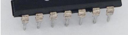
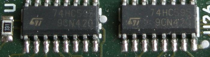
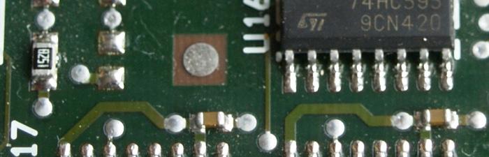
26 Using 74* 74 chips 51 Using 74* 74 chips Breadboard +74* chips 52
27 Using a PLA It s a programmable device You can implement your own (complex) combinational logic (=function) using a single PLA A PLA device is much more capable than individual 74* chips Much denser (that means you can implement many functions) Internally, PLA implements a function of the sum-ofproduct format AND plane for product terms OR plane for summing products 53 PLA design of ALU control logic products sums 54

28 FPGA FPGA is even more capable (millions of gates) Combinational logic Sequential logic Memory arrays Even some embedded d microprocessor cores I/O support such as Ethernet MAC (media access control) block Best of all, it s field programmable and affordable 55 To wrap up In digital logic, transistors are used as simple switches Logic gates are an abstraction of a transistor network A combinational i logic block has inputs and outputs whose values are immediately determined as inputs become known A sequential logic block is composed of a combinational logic block and memory elements 56
29 To wrap up Boolean algebra provides a theoretical foundation for digital logic Starting from two transistors (N-type and P-type), we ve built logic gates and more complex structures (bottom up) An ALU for the MIPS architecture has been built! 57 To wrap up Flip-flops p (FFs) were used as a memory element A finite state machine (FSM) can be implemented using FFs and some combinational logic 58
CS/COE0447: Computer Organization
 Logic design? CS/COE0447: Computer Organization and Assembly Language Logic Design Review Digital hardware is implemented by way of logic design Digital circuits process and produce two discrete values:
CS/COE1541: Introduction to Computer Architecture. Logic Design Review. Sangyeun Cho. Computer Science Department University of Pittsburgh
 CS/COE54: Introduction to Computer Architecture Logic Design Review Sangyeun Cho Computer Science Department Logic design? Digital hardware is implemented by way of logic design Digital circuits process
Logic design? Transistor as a switch. Layered design approach. CS/COE1541: Introduction to Computer Architecture. Logic Design Review.
 Logic design? CS/COE54: Introduction to Computer rchitecture Digital hardware is implemented by way of logic design Digital circuits process and produce two discrete values: and Example: -bit full adder
CS/COE0447: Computer Organization and Assembly Language
 CS/COE0447: Computer Organization and Assembly Language Logic Design Introduction (Brief?) Appendix B: The Basics of Logic Design Dept. of Computer Science Logic design? Digital hardware is implemented
Lecture 13: Sequential Circuits, FSM
 Lecture 13: Sequential Circuits, FSM Today s topics: Sequential circuits Finite state machines 1 Clocks A microprocessor is composed of many different circuits that are operating simultaneously if each
Digital Logic: Boolean Algebra and Gates. Textbook Chapter 3
 Digital Logic: Boolean Algebra and Gates Textbook Chapter 3 Basic Logic Gates XOR CMPE12 Summer 2009 02-2 Truth Table The most basic representation of a logic function Lists the output for all possible
Lecture 7: Logic design. Combinational logic circuits
 /24/28 Lecture 7: Logic design Binary digital circuits: Two voltage levels: and (ground and supply voltage) Built from transistors used as on/off switches Analog circuits not very suitable for generic
Boolean Algebra and Digital Logic 2009, University of Colombo School of Computing
 IT 204 Section 3.0 Boolean Algebra and Digital Logic Boolean Algebra 2 Logic Equations to Truth Tables X = A. B + A. B + AB A B X 0 0 0 0 3 Sum of Products The OR operation performed on the products of
Latches. October 13, 2003 Latches 1
 Latches The second part of CS231 focuses on sequential circuits, where we add memory to the hardware that we ve already seen. Our schedule will be very similar to before: We first show how primitive memory
Chapter 4. Sequential Logic Circuits
 Chapter 4 Sequential Logic Circuits 1 2 Chapter 4 4 1 The defining characteristic of a combinational circuit is that its output depends only on the current inputs applied to the circuit. The output of
Digital Logic Appendix A
 Digital Logic Appendix A Boolean Algebra Gates Combinatorial Circuits Sequential Circuits 1 Boolean Algebra George Boole ideas 1854 Claude Shannon, apply to circuit design, 1938 Describe digital circuitry
Sequential Logic Circuits
 Chapter 4 Sequential Logic Circuits 4 1 The defining characteristic of a combinational circuit is that its output depends only on the current inputs applied to the circuit. The output of a sequential circuit,
Lecture 13: Sequential Circuits, FSM
 Lecture 13: Sequential Circuits, FSM Today s topics: Sequential circuits Finite state machines Reminder: midterm on Tue 2/28 will cover Chapters 1-3, App A, B if you understand all slides, assignments,
Digital Logic. CS211 Computer Architecture. l Topics. l Transistors (Design & Types) l Logic Gates. l Combinational Circuits.
 l Logic Gates. l Combinational Circuits.") CS211 Computer Architecture Digital Logic l Topics l Transistors (Design & Types) l Logic Gates l Combinational Circuits l K-Maps Figures & Tables borrowed from:! http://www.allaboutcircuits.com/vol_4/index.html!
CS211 Computer Architecture Digital Logic l Topics l Transistors (Design & Types) l Logic Gates l Combinational Circuits l K-Maps Figures & Tables borrowed from:! http://www.allaboutcircuits.com/vol_4/index.html!
CSC9R6 Computer Design. Practical Digital Logic
 CSC9R6 Computer Design Practical Digital Logic 1 References (for this part of CSC9R6) Hamacher et al: Computer Organization App A. In library Floyd: Digital Fundamentals Ch 1, 3-6, 8-10 web page: www.prenhall.com/floyd/
CS470: Computer Architecture. AMD Quad Core
 CS470: Computer Architecture Yashwant K. Malaiya, Professor malaiya@cs.colostate.edu AMD Quad Core 1 Architecture Layers Building blocks Gates, flip-flops Functional bocks: Combinational, Sequential Instruction
Fundamentals of Digital Design
 Fundamentals of Digital Design Digital Radiation Measurement and Spectroscopy NE/RHP 537 1 Binary Number System The binary numeral system, or base-2 number system, is a numeral system that represents numeric
Sequential Logic. Rab Nawaz Khan Jadoon DCS. Lecturer COMSATS Lahore Pakistan. Department of Computer Science
 Sequential Logic Rab Nawaz Khan Jadoon DCS COMSATS Institute of Information Technology Lecturer COMSATS Lahore Pakistan Digital Logic and Computer Design Sequential Logic Combinational circuits with memory
Appendix B. Review of Digital Logic. Baback Izadi Division of Engineering Programs
 Appendix B Review of Digital Logic Baback Izadi Division of Engineering Programs bai@engr.newpaltz.edu Elect. & Comp. Eng. 2 DeMorgan Symbols NAND (A.B) = A +B NOR (A+B) = A.B AND A.B = A.B = (A +B ) OR
Philadelphia University Student Name: Student Number:
 Philadelphia University Student Name: Student Number: Faculty of Engineering Serial Number: Final Exam, First Semester: 2017/2018 Dept. of Computer Engineering Course Title: Logic Circuits Date: 29/01/2018
CS61C : Machine Structures
 inst.eecs.berkeley.edu/~cs61c/su05 CS61C : Machine Structures Lecture #15: Combinational Logic Blocks 2005-07-14 CS 61C L15 Blocks (1) Andy Carle Outline CL Blocks Latches & Flip Flops A Closer Look CS
ELCT201: DIGITAL LOGIC DESIGN
 ELCT201: DIGITAL LOGIC DESIGN Dr. Eng. Haitham Omran, haitham.omran@guc.edu.eg Dr. Eng. Wassim Alexan, wassim.joseph@guc.edu.eg Lecture 6 Following the slides of Dr. Ahmed H. Madian محرم 1439 ه Winter
ECE/CS 250 Computer Architecture
 ECE/CS 250 Computer Architecture Basics of Logic Design: Boolean Algebra, Logic Gates (Combinational Logic) Tyler Bletsch Duke University Slides are derived from work by Daniel J. Sorin (Duke), Alvy Lebeck
Boolean Algebra. Digital Logic Appendix A. Postulates, Identities in Boolean Algebra How can I manipulate expressions?
 Digital Logic Appendix A Gates Combinatorial Circuits Sequential Circuits Other operations NAND A NAND B = NOT ( A ANDB) = AB NOR A NOR B = NOT ( A ORB) = A + B Truth tables What is the result of the operation
EE40 Lec 15. Logic Synthesis and Sequential Logic Circuits
 EE40 Lec 15 Logic Synthesis and Sequential Logic Circuits Prof. Nathan Cheung 10/20/2009 Reading: Hambley Chapters 7.4-7.6 Karnaugh Maps: Read following before reading textbook http://www.facstaff.bucknell.edu/mastascu/elessonshtml/logic/logic3.html
ECE 250 / CPS 250 Computer Architecture. Basics of Logic Design Boolean Algebra, Logic Gates
 ECE 250 / CPS 250 Computer Architecture Basics of Logic Design Boolean Algebra, Logic Gates Benjamin Lee Slides based on those from Andrew Hilton (Duke), Alvy Lebeck (Duke) Benjamin Lee (Duke), and Amir
Vidyalankar S.E. Sem. III [CMPN] Digital Logic Design and Analysis Prelim Question Paper Solution
![Vidyalankar S.E. Sem. III [CMPN] Digital Logic Design and Analysis Prelim Question Paper Solution](/thumbs/90/103673562.jpg "Vidyalankar S.E. Sem. III [CMPN] Digital Logic Design and Analysis Prelim Question Paper Solution") . (a) (i) ( B C 5) H (A 2 B D) H S.E. Sem. III [CMPN] Digital Logic Design and Analysis Prelim Question Paper Solution ( B C 5) H (A 2 B D) H = (FFFF 698) H (ii) (2.3) 4 + (22.3) 4 2 2. 3 2. 3 2 3. 2 (2.3)
. (a) (i) ( B C 5) H (A 2 B D) H S.E. Sem. III [CMPN] Digital Logic Design and Analysis Prelim Question Paper Solution ( B C 5) H (A 2 B D) H = (FFFF 698) H (ii) (2.3) 4 + (22.3) 4 2 2. 3 2. 3 2 3. 2 (2.3)
ECEN 248: INTRODUCTION TO DIGITAL SYSTEMS DESIGN. Week 9 Dr. Srinivas Shakkottai Dept. of Electrical and Computer Engineering
 ECEN 248: INTRODUCTION TO DIGITAL SYSTEMS DESIGN Week 9 Dr. Srinivas Shakkottai Dept. of Electrical and Computer Engineering TIMING ANALYSIS Overview Circuits do not respond instantaneously to input changes
SAU1A FUNDAMENTALS OF DIGITAL COMPUTERS
 SAU1A FUNDAMENTALS OF DIGITAL COMPUTERS Unit : I - V Unit : I Overview Fundamentals of Computers Characteristics of Computers Computer Language Operating Systems Generation of Computers 2 Definition of
 vidyarthiplus.com vidyarthiplus.com vidyarthiplus.com ANNA UNIVERSITY- COMBATORE B.E./ B.TECH. DEGREE EXAMINATION - JUNE 2009. ELECTRICAL & ELECTONICS ENGG. - FOURTH SEMESTER DIGITAL LOGIC CIRCUITS PART-A
Review for B33DV2-Digital Design. Digital Design
 Review for B33DV2 The Elements of Modern Behaviours Design Representations Blocks Waveforms Gates Truth Tables Boolean Algebra Switches Rapid Prototyping Technologies Circuit Technologies TTL MOS Simulation
CS61C : Machine Structures
 CS 61C L15 Blocks (1) inst.eecs.berkeley.edu/~cs61c/su05 CS61C : Machine Structures Lecture #15: Combinational Logic Blocks Outline CL Blocks Latches & Flip Flops A Closer Look 2005-07-14 Andy Carle CS
( c) Give logic symbol, Truth table and circuit diagram for a clocked SR flip-flop. A combinational circuit is defined by the function
 Give logic symbol, Truth table and circuit diagram for a clocked SR flip-flop. A combinational circuit is defined by the function") Question Paper Digital Electronics (EE-204-F) MDU Examination May 2015 1. (a) represent (32)10 in (i) BCD 8421 code (ii) Excess-3 code (iii) ASCII code (b) Design half adder using only NAND gates. ( c)
Question Paper Digital Electronics (EE-204-F) MDU Examination May 2015 1. (a) represent (32)10 in (i) BCD 8421 code (ii) Excess-3 code (iii) ASCII code (b) Design half adder using only NAND gates. ( c)
Memory Elements I. CS31 Pascal Van Hentenryck. CS031 Lecture 6 Page 1
 Memory Elements I CS31 Pascal Van Hentenryck CS031 Lecture 6 Page 1 Memory Elements (I) Combinational devices are good for computing Boolean functions pocket calculator Computers also need to remember
Lecture 22 Chapters 3 Logic Circuits Part 1
 Lecture 22 Chapters 3 Logic Circuits Part 1 LC-3 Data Path Revisited How are the components Seen here implemented? 5-2 Computing Layers Problems Algorithms Language Instruction Set Architecture Microarchitecture
XI STANDARD [ COMPUTER SCIENCE ] 5 MARKS STUDY MATERIAL.
![XI STANDARD [ COMPUTER SCIENCE ] 5 MARKS STUDY MATERIAL.](/thumbs/81/84726747.jpg "XI STANDARD [ COMPUTER SCIENCE ] 5 MARKS STUDY MATERIAL.") 2017-18 XI STANDARD [ COMPUTER SCIENCE ] 5 MARKS STUDY MATERIAL HALF ADDER 1. The circuit that performs addition within the Arithmetic and Logic Unit of the CPU are called adders. 2. A unit that adds two
2017-18 XI STANDARD [ COMPUTER SCIENCE ] 5 MARKS STUDY MATERIAL HALF ADDER 1. The circuit that performs addition within the Arithmetic and Logic Unit of the CPU are called adders. 2. A unit that adds two
ECE/CS 250: Computer Architecture. Basics of Logic Design: Boolean Algebra, Logic Gates. Benjamin Lee
 ECE/CS 250: Computer Architecture Basics of Logic Design: Boolean Algebra, Logic Gates Benjamin Lee Slides based on those from Alvin Lebeck, Daniel Sorin, Andrew Hilton, Amir Roth, Gershon Kedem Admin
Unit II Chapter 4:- Digital Logic Contents 4.1 Introduction... 4
 Unit II Chapter 4:- Digital Logic Contents 4.1 Introduction... 4 4.1.1 Signal... 4 4.1.2 Comparison of Analog and Digital Signal... 7 4.2 Number Systems... 7 4.2.1 Decimal Number System... 7 4.2.2 Binary
CMPE12 - Notes chapter 1. Digital Logic. (Textbook Chapter 3)
") CMPE12 - Notes chapter 1 Digital Logic (Textbook Chapter 3) Transistor: Building Block of Computers Microprocessors contain TONS of transistors Intel Montecito (2005): 1.72 billion Intel Pentium 4 (2000):
CMPE12 - Notes chapter 1 Digital Logic (Textbook Chapter 3) Transistor: Building Block of Computers Microprocessors contain TONS of transistors Intel Montecito (2005): 1.72 billion Intel Pentium 4 (2000):
Reg. No. Question Paper Code : B.E./B.Tech. DEGREE EXAMINATION, NOVEMBER/DECEMBER Second Semester. Computer Science and Engineering
 Sp 6 Reg. No. Question Paper Code : 27156 B.E./B.Tech. DEGREE EXAMINATION, NOVEMBER/DECEMBER 2015. Second Semester Computer Science and Engineering CS 6201 DIGITAL PRINCIPLES AND SYSTEM DESIGN (Common
Review for Final Exam
 CSE140: Components and Design Techniques for Digital Systems Review for Final Exam Mohsen Imani CAPE Please submit your evaluations!!!! RTL design Use the RTL design process to design a system that has
CMPE12 - Notes chapter 2. Digital Logic. (Textbook Chapters and 2.1)"
") CMPE12 - Notes chapter 2 Digital Logic (Textbook Chapters 3.1-3.5 and 2.1)" Truth table" The most basic representation of a logic function." Brute force representation listing the output for all possible
CMPE12 - Notes chapter 2 Digital Logic (Textbook Chapters 3.1-3.5 and 2.1)" Truth table" The most basic representation of a logic function." Brute force representation listing the output for all possible
Chapter 3 Digital Logic Structures
 Chapter 3 Digital Logic Structures Original slides from Gregory Byrd, North Carolina State University Modified by C. Wilcox, M. Strout, Y. Malaiya Colorado State University Computing Layers Problems Algorithms
Lecture 3 Review on Digital Logic (Part 2)
") Lecture 3 Review on Digital Logic (Part 2) Xuan Silvia Zhang Washington University in St. Louis http://classes.engineering.wustl.edu/ese461/ ircuit Optimization Simplest implementation ost criterion literal
Lecture 3 Review on Digital Logic (Part 2) Xuan Silvia Zhang Washington University in St. Louis http://classes.engineering.wustl.edu/ese461/ ircuit Optimization Simplest implementation ost criterion literal
Boolean algebra. Examples of these individual laws of Boolean, rules and theorems for Boolean algebra are given in the following table.
 The Laws of Boolean Boolean algebra As well as the logic symbols 0 and 1 being used to represent a digital input or output, we can also use them as constants for a permanently Open or Closed circuit or
Number System. Decimal to binary Binary to Decimal Binary to octal Binary to hexadecimal Hexadecimal to binary Octal to binary
 Number System Decimal to binary Binary to Decimal Binary to octal Binary to hexadecimal Hexadecimal to binary Octal to binary BOOLEAN ALGEBRA BOOLEAN LOGIC OPERATIONS Logical AND Logical OR Logical COMPLEMENTATION
Chapter 7. Sequential Circuits Registers, Counters, RAM
 Chapter 7. Sequential Circuits Registers, Counters, RAM Register - a group of binary storage elements suitable for holding binary info A group of FFs constitutes a register Commonly used as temporary storage
LOGIC CIRCUITS. Basic Experiment and Design of Electronics
 Basic Experiment and Design of Electronics LOGIC CIRCUITS Ho Kyung Kim, Ph.D. hokyung@pusan.ac.kr School of Mechanical Engineering Pusan National University Outline Combinational logic circuits Output
Combinatorial Logic Design Multiplexers and ALUs CS 64: Computer Organization and Design Logic Lecture #13
 Combinatorial Logic Design Multiplexers and ALUs CS 64: Computer Organization and Design Logic Lecture #13 Ziad Matni Dept. of Computer Science, UCSB Administrative Re: Midterm Exam #2 Graded! 5/22/18
Boolean Algebra. Digital Logic Appendix A. Boolean Algebra Other operations. Boolean Algebra. Postulates, Identities in Boolean Algebra
 Digital Logic Appendix A Gates Combinatorial Circuits Sequential Circuits George Boole ideas 1854 Claude Shannon, apply to circuit design, 1938 (piirisuunnittelu) Describe digital circuitry function programming
Principles of Computer Architecture. Appendix B: Reduction of Digital Logic. Chapter Contents
 B-1 Principles of Computer Architecture Miles Murdocca and Vincent Heuring Appendix B: Reduction of Digital Logic B-2 Chapter Contents B.1 Reduction of Combinational Logic and Sequential Logic B.2 Reduction
WORKBOOK. Try Yourself Questions. Electrical Engineering Digital Electronics. Detailed Explanations of
 27 WORKBOOK Detailed Eplanations of Try Yourself Questions Electrical Engineering Digital Electronics Number Systems and Codes T : Solution Converting into decimal number system 2 + 3 + 5 + 8 2 + 4 8 +
DIGITAL LOGIC CIRCUITS
 DIGITAL LOGIC CIRCUITS Introduction Logic Gates Boolean Algebra Map Specification Combinational Circuits Flip-Flops Sequential Circuits Memory Components Integrated Circuits Digital Computers 2 LOGIC GATES
CSC 322: Computer Organization Lab
 CSC 322: Computer Organization Lab Lecture 3: Logic Design Dr. Haidar M. Harmanani CSC 322: Computer Organization Lab Part I: Combinational Logic Dr. Haidar M. Harmanani Logical Design of Digital Systems
UNIT 8A Computer Circuitry: Layers of Abstraction. Boolean Logic & Truth Tables
 UNIT 8 Computer Circuitry: Layers of bstraction 1 oolean Logic & Truth Tables Computer circuitry works based on oolean logic: operations on true (1) and false (0) values. ( ND ) (Ruby: && ) 0 0 0 0 0 1
Switches: basic element of physical implementations
 Combinational logic Switches Basic logic and truth tables Logic functions Boolean algebra Proofs by re-writing and by perfect induction Winter 200 CSE370 - II - Boolean Algebra Switches: basic element
DIGITAL LOGIC CIRCUITS
 DIGITAL LOGIC CIRCUITS Digital logic circuits BINARY NUMBER SYSTEM electronic circuits that handle information encoded in binary form (deal with signals that have only two values, and ) Digital. computers,
EEE130 Digital Electronics I Lecture #4
 EEE130 Digital Electronics I Lecture #4 - Boolean Algebra and Logic Simplification - By Dr. Shahrel A. Suandi Topics to be discussed 4-1 Boolean Operations and Expressions 4-2 Laws and Rules of Boolean
Hakim Weatherspoon CS 3410 Computer Science Cornell University
 Hakim Weatherspoon CS 3410 Computer Science Cornell University The slides are the product of many rounds of teaching CS 3410 by Professors Weatherspoon, Bala, Bracy, and Sirer. memory inst 32 register
Fundamentals of Computer Systems
 Fundamentals of Computer Systems Review for the Final Stephen A. Edwards Columbia University Summer 25 The Final 2 hours 8 problems Closed book Simple calculators are OK, but unnecessary One double-sided
Synchronous Sequential Logic
 1 IT 201 DIGITAL SYSTEMS DESIGN MODULE4 NOTES Synchronous Sequential Logic Sequential Circuits - A sequential circuit consists of a combinational circuit and a feedback through the storage elements in
Systems I: Computer Organization and Architecture
 Systems I: Computer Organization and Architecture Lecture 6 - Combinational Logic Introduction A combinational circuit consists of input variables, logic gates, and output variables. The logic gates accept
Combinational vs. Sequential. Summary of Combinational Logic. Combinational device/circuit: any circuit built using the basic gates Expressed as
 Summary of Combinational Logic : Computer Architecture I Instructor: Prof. Bhagi Narahari Dept. of Computer Science Course URL: www.seas.gwu.edu/~bhagiweb/cs3/ Combinational device/circuit: any circuit
MAHARASHTRA STATE BOARD OF TECHNICAL EDUCATION (Autonomous) (ISO/IEC Certified)
 (ISO/IEC Certified)") WINTER 17 EXAMINATION Subject Name: Digital Techniques Model Answer Subject Code: 17333 Important Instructions to examiners: 1) The answers should be examined by key words and not as word-to-word as given
WINTER 17 EXAMINATION Subject Name: Digital Techniques Model Answer Subject Code: 17333 Important Instructions to examiners: 1) The answers should be examined by key words and not as word-to-word as given
on candidate s understanding. 7) For programming language papers, credit may be given to any other program based on equivalent concept.
 For programming language papers, credit may be given to any other program based on equivalent concept.") WINTER 17 EXAMINATION Subject Name: Digital Techniques Model Answer Subject Code: 17333 Important Instructions to examiners: 1) The answers should be examined by key words and not as word-to-word as given
WINTER 17 EXAMINATION Subject Name: Digital Techniques Model Answer Subject Code: 17333 Important Instructions to examiners: 1) The answers should be examined by key words and not as word-to-word as given
S.Y. Diploma : Sem. III [DE/ED/EI/EJ/EN/ET/EV/EX/IC/IE/IS/IU/MU] Principles of Digital Techniques
![S.Y. Diploma : Sem. III [DE/ED/EI/EJ/EN/ET/EV/EX/IC/IE/IS/IU/MU] Principles of Digital Techniques](/thumbs/82/86792063.jpg "S.Y. Diploma : Sem. III [DE/ED/EI/EJ/EN/ET/EV/EX/IC/IE/IS/IU/MU] Principles of Digital Techniques") S.Y. Diploma : Sem. III [DE/ED/EI/EJ/EN/ET/EV/EX/IC/IE/IS/IU/MU] Principles of Digital Techniques Time: 3 Hrs.] Prelim Question Paper Solution [Marks : 100 Q.1(a) Attempt any SIX of the following : [12]
S.Y. Diploma : Sem. III [DE/ED/EI/EJ/EN/ET/EV/EX/IC/IE/IS/IU/MU] Principles of Digital Techniques Time: 3 Hrs.] Prelim Question Paper Solution [Marks : 100 Q.1(a) Attempt any SIX of the following : [12]
Sample Test Paper - I
 Scheme G Sample Test Paper - I Course Name : Computer Engineering Group Marks : 25 Hours: 1 Hrs. Q.1) Attempt any THREE: 09 Marks a) Define i) Propagation delay ii) Fan-in iii) Fan-out b) Convert the following:
Review for Test 1 : Ch1 5
 Review for Test 1 : Ch1 5 October 5, 2006 Typeset by FoilTEX Positional Numbers 527.46 10 = (5 10 2 )+(2 10 1 )+(7 10 0 )+(4 10 1 )+(6 10 2 ) 527.46 8 = (5 8 2 ) + (2 8 1 ) + (7 8 0 ) + (4 8 1 ) + (6 8
Chapter 7 Logic Circuits
 Chapter 7 Logic Circuits Goal. Advantages of digital technology compared to analog technology. 2. Terminology of Digital Circuits. 3. Convert Numbers between Decimal, Binary and Other forms. 5. Binary
CSE140: Components and Design Techniques for Digital Systems. Midterm Information. Instructor: Mohsen Imani. Sources: TSR, Katz, Boriello & Vahid
 CSE140: Components and Design Techniques for Digital Systems Midterm Information Instructor: Mohsen Imani Midterm Topics In general: everything that was covered in homework 1 and 2 and related lectures,
ECE 2300 Digital Logic & Computer Organization
 ECE 23 Digital Logic & Computer Organization Spring 28 Combinational Building Blocks Lecture 5: Announcements Lab 2 prelab due tomorrow HW due Friday HW 2 to be posted on Thursday Lecture 4 to be replayed
UNIVERSITY OF WISCONSIN MADISON
 CS/ECE 252: INTRODUCTION TO COMPUTER ENGINEERING UNIVERSITY OF WISCONSIN MADISON Prof. Gurindar Sohi TAs: Minsub Shin, Lisa Ossian, Sujith Surendran Midterm Examination 2 In Class (50 minutes) Friday,
Sequential Circuit Analysis
 Sequential Circuit Analysis Last time we started talking about latches and flip-flops, which are basic one-bit memory units. Today we ll talk about sequential circuit analysis and design. First, we ll
LOGIC CIRCUITS. Basic Experiment and Design of Electronics. Ho Kyung Kim, Ph.D.
 Basic Experiment and Design of Electronics LOGIC CIRCUITS Ho Kyung Kim, Ph.D. hokyung@pusan.ac.kr School of Mechanical Engineering Pusan National University Digital IC packages TTL (transistor-transistor
ECEN 248: INTRODUCTION TO DIGITAL SYSTEMS DESIGN. Week 7 Dr. Srinivas Shakkottai Dept. of Electrical and Computer Engineering
 ECEN 248: INTRODUCTION TO DIGITAL SYSTEMS DESIGN Week 7 Dr. Srinivas Shakkottai Dept. of Electrical and Computer Engineering SEQUENTIAL CIRCUITS: LATCHES Overview Circuits require memory to store intermediate
Menu. 7-Segment LED. Misc. 7-Segment LED MSI Components >MUX >Adders Memory Devices >D-FF, RAM, ROM Computer/Microprocessor >GCPU
 Menu 7-Segment LED MSI Components >MUX >Adders Memory Devices >D-FF, RAM, ROM Computer/Microprocessor >GCPU Look into my... 1 7-Segment LED a b c h GND c g b d f a e h Show 7-segment LED in LogicWorks,
University of Toronto Faculty of Applied Science and Engineering Edward S. Rogers Sr. Department of Electrical and Computer Engineering
 University of Toronto Faculty of Applied Science and Engineering Edward S. Rogers Sr. Department of Electrical and Computer Engineering Final Examination ECE 241F - Digital Systems Examiners: J. Rose and
Introduction to Computer Engineering. CS/ECE 252, Fall 2012 Prof. Guri Sohi Computer Sciences Department University of Wisconsin Madison
 Introduction to Computer Engineering CS/ECE 252, Fall 2012 Prof. Guri Sohi Computer Sciences Department University of Wisconsin Madison Chapter 3 Digital Logic Structures Slides based on set prepared by
Time Allowed 3:00 hrs. April, pages
 IGITAL ESIGN COEN 32 Prof. r. A. J. Al-Khalili Time Allowed 3: hrs. April, 998 2 pages Answer All uestions No materials are allowed uestion a) esign a half subtractor b) esign a full subtractor c) Using
Design of Sequential Circuits
 Design of Sequential Circuits Seven Steps: Construct a state diagram (showing contents of flip flop and inputs with next state) Assign letter variables to each flip flop and each input and output variable
4 Switching Algebra 4.1 Axioms; Signals and Switching Algebra
 4 Switching Algebra 4.1 Axioms; Signals and Switching Algebra To design a digital circuit that will perform a required function, it is necessary to manipulate and combine the various input signals in certain
DHANALAKSHMI COLLEGE OF ENGINEERING, CHENNAI DEPARTMENT OF COMPUTER SCIENCE AND ENGINEERING CS6201 DIGITAL PRINCIPLES AND SYSTEM DESIGN
 DHANALAKSHMI COLLEGE OF ENGINEERING, CHENNAI DEPARTMENT OF COMPUTER SCIENCE AND ENGINEERING CS6201 DIGITAL PRINCIPLES AND SYSTEM DESIGN UNIT I : BOOLEAN ALGEBRA AND LOGIC GATES PART - A (2 MARKS) Number
Computer organization
 Computer organization Levels of abstraction Assembler Simulator Applications C C++ Java High-level language SOFTWARE add lw ori Assembly language Goal 0000 0001 0000 1001 0101 Machine instructions/data
CHAPTER1: Digital Logic Circuits Combination Circuits
 CS224: Computer Organization S.KHABET CHAPTER1: Digital Logic Circuits Combination Circuits 1 PRIMITIVE LOGIC GATES Each of our basic operations can be implemented in hardware using a primitive logic gate.
INF2270 Spring Philipp Häfliger. Lecture 8: Superscalar CPUs, Course Summary/Repetition (1/2)
") INF2270 Spring 2010 Philipp Häfliger Summary/Repetition (1/2) content From Scalar to Superscalar Lecture Summary and Brief Repetition Binary numbers Boolean Algebra Combinational Logic Circuits Encoder/Decoder
INF2270 Spring 2010 Philipp Häfliger Summary/Repetition (1/2) content From Scalar to Superscalar Lecture Summary and Brief Repetition Binary numbers Boolean Algebra Combinational Logic Circuits Encoder/Decoder
ALU A functional unit
 ALU A functional unit that performs arithmetic operations such as ADD, SUB, MPY logical operations such as AND, OR, XOR, NOT on given data types: 8-,16-,32-, or 64-bit values A n-1 A n-2... A 1 A 0 B n-1
Lecture A: Logic Design and Gates
 Lecture A: Logic Design and Gates Syllabus My office hours 9.15-10.35am T,Th or gchoi@ece.tamu.edu 333G WERC Text: Brown and Vranesic Fundamentals of Digital Logic,» Buy it.. Or borrow it» Other book:
Department of Electrical & Electronics EE-333 DIGITAL SYSTEMS
 Department of Electrical & Electronics EE-333 DIGITAL SYSTEMS 1) Given the two binary numbers X = 1010100 and Y = 1000011, perform the subtraction (a) X -Y and (b) Y - X using 2's complements. a) X = 1010100
UNIVERSITY OF BOLTON SCHOOL OF ENGINEERING BENG (HONS) ELECTRICAL & ELECTRONICS ENGINEERING EXAMINATION SEMESTER /2017
 ELECTRICAL & ELECTRONICS ENGINEERING EXAMINATION SEMESTER /2017") UNIVERSITY OF BOLTON TW35 SCHOOL OF ENGINEERING BENG (HONS) ELECTRICAL & ELECTRONICS ENGINEERING EXAMINATION SEMESTER 2-2016/2017 INTERMEDIATE DIGITAL ELECTRONICS AND COMMUNICATIONS MODULE NO: EEE5002
UNIVERSITY OF BOLTON TW35 SCHOOL OF ENGINEERING BENG (HONS) ELECTRICAL & ELECTRONICS ENGINEERING EXAMINATION SEMESTER 2-2016/2017 INTERMEDIATE DIGITAL ELECTRONICS AND COMMUNICATIONS MODULE NO: EEE5002
Chapter 14 Sequential logic, Latches and Flip-Flops
 Chapter 14 Sequential logic, Latches and Flip-Flops Flops Lesson 4 JK Flip Flop Ch14L4-"Digital Principles and Design", Raj Kamal, Pearson Education, 2006 2 JK Flip-Flop ve edge triggered Output Q and
2. Associative Law: A binary operator * on a set S is said to be associated whenever (A*B)*C = A*(B*C) for all A,B,C S.
*C = A*(B*C) for all A,B,C S.") BOOLEAN ALGEBRA 2.1 Introduction Binary logic deals with variables that have two discrete values: 1 for TRUE and 0 for FALSE. A simple switching circuit containing active elements such as a diode and transistor
BOOLEAN ALGEBRA 2.1 Introduction Binary logic deals with variables that have two discrete values: 1 for TRUE and 0 for FALSE. A simple switching circuit containing active elements such as a diode and transistor
ELEC Digital Logic Circuits Fall 2014 Sequential Circuits (Chapter 6) Finite State Machines (Ch. 7-10)
 Finite State Machines (Ch. 7-10)") ELEC 2200-002 Digital Logic Circuits Fall 2014 Sequential Circuits (Chapter 6) Finite State Machines (Ch. 7-10) Vishwani D. Agrawal James J. Danaher Professor Department of Electrical and Computer Engineering
ELEC 2200-002 Digital Logic Circuits Fall 2014 Sequential Circuits (Chapter 6) Finite State Machines (Ch. 7-10) Vishwani D. Agrawal James J. Danaher Professor Department of Electrical and Computer Engineering
Digital Logic (2) Boolean Algebra
 Boolean Algebra") Digital Logic (2) Boolean Algebra Boolean algebra is the mathematics of digital systems. It was developed in 1850 s by George Boole. We will use Boolean algebra to minimize logic expressions. Karnaugh
Digital Logic (2) Boolean Algebra Boolean algebra is the mathematics of digital systems. It was developed in 1850 s by George Boole. We will use Boolean algebra to minimize logic expressions. Karnaugh
Floating Point Representation and Digital Logic. Lecture 11 CS301
 Floating Point Representation and Digital Logic Lecture 11 CS301 Administrative Daily Review of today s lecture w Due tomorrow (10/4) at 8am Lab #3 due Friday (9/7) 1:29pm HW #5 assigned w Due Monday 10/8
ENGG 1203 Tutorial_9 - Review. Boolean Algebra. Simplifying Logic Circuits. Combinational Logic. 1. Combinational & Sequential Logic
 ENGG 1203 Tutorial_9 - Review Boolean Algebra 1. Combinational & Sequential Logic 2. Computer Systems 3. Electronic Circuits 4. Signals, Systems, and Control Remark : Multiple Choice Questions : ** Check
CS 226: Digital Logic Design
 CS 226: Digital Logic Design 0 1 1 I S 0 1 0 S Department of Computer Science and Engineering, Indian Institute of Technology Bombay. 1 of 29 Objectives In this lecture we will introduce: 1. Logic functions
KUMARAGURU COLLEGE OF TECHNOLOGY COIMBATORE
 Estd-1984 KUMARAGURU COLLEGE OF TECHNOLOGY COIMBATORE 641 006 QUESTION BANK UNIT I PART A ISO 9001:2000 Certified 1. Convert (100001110.010) 2 to a decimal number. 2. Find the canonical SOP for the function
CS61c: Representations of Combinational Logic Circuits
 CS61c: Representations of Combinational Logic Circuits J. Wawrzynek March 5, 2003 1 Introduction Recall that synchronous systems are composed of two basic types of circuits, combination logic circuits,
ENGG 1203 Tutorial _03 Laboratory 3 Build a ball counter. Lab 3. Lab 3 Gate Timing. Lab 3 Steps in designing a State Machine. Timing diagram of a DFF
 ENGG 1203 Tutorial _03 Laboratory 3 Build a ball counter Timing diagram of a DFF Lab 3 Gate Timing difference timing for difference kind of gate, cost dependence (1) Setup Time = t2-t1 (2) Propagation
Logic. Basic Logic Functions. Switches in series (AND) Truth Tables. Switches in Parallel (OR) Alternative view for OR
 Truth Tables. Switches in Parallel (OR) Alternative view for OR") TOPIS: Logic Logic Expressions Logic Gates Simplifying Logic Expressions Sequential Logic (Logic with a Memory) George oole (85-864), English mathematician, oolean logic used in digital computers since
TOPIS: Logic Logic Expressions Logic Gates Simplifying Logic Expressions Sequential Logic (Logic with a Memory) George oole (85-864), English mathematician, oolean logic used in digital computers since