Outcome of this lecture
|
|
|
- Evangeline Walker
- 5 years ago
- Views:
Transcription
1 Outcome of this lecture At the en of this lecture you will be able to: List the ifferent parts of a synchronous machine Explain the operation principles of the machine Use the equivalent circuit moel of the machine Analyze the steay-state operation of the machine Calculate the power transfer of the machine (Torque, power, power factor, etc ) Your will unerstan the ifference between salient pole an non-salient pole machines
 Experimental etermination of reactances alient pole machine phasor iagrams an power")
2 Contents of this lecture tructure, construction an use of synchronous machines Infinite bus an synchronization Equivalent circuit of synchronous machine Performance characteristics (torque, power, power factor, etc ) Experimental etermination of reactances alient pole machine phasor iagrams an power transfer

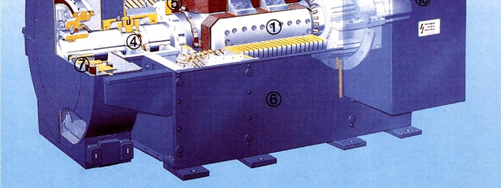
3 tructure of synchronous machines

4 tructure of synchronous machines


5 Main characteristics Rotates at constant spee. Primary energy conversion evices of the wor s electric power system. Both generator an motor operations Can raw either a lagging or a leaing reactive current from the supply.
6 Usage of ifferent types of synch. machines on-salient pole generator High spee (2-4 poles) Large power ( MVA) team power plants alient pole generator Low spee mall an mi-size power (0 800 MVA) Motors for electrical omestic evices Mi size generators for emergency power supply Motors for pumps an ship propulsion Large size generators in hyro-electric power plants
7 3-phase voltage generation imple generator e = F t 400 a 300 e a e b 200 e c inuce voltage (V) a Time (s)
8 Connecting the 3-phase voltages 3 single-phase circuits at ifferent phase angle! Z = ( ) Z = ( ) Z = ( ) = = (2 + )
9 Connecting the 3-phase voltages The potential ifference is known but not the potentials! = ( ) = ( ) = + + =3
10 ynchronous Generators o-loa Excitation voltages Frequency epens on the spee np 120 f f = n = 120 p 2p Ef = f F fkw Ef nf f 2 Open circuit characteristics Magnetization characteristics
11 ynchronous Generators - loae tator currents establish a rotating fiel in the air-gap Armature reaction flux a Resultant air-gap flux F = F + F r f a

12 The infinite bus The quasi totality of the electric power generate worlwie is three-phase. Power plants International links ubstations an Transformer Transmission lines Loa centers Inustrial an Resiential loas
13 Paralleling with the infinite bus ame Voltage Frequency Phase sequence Phase same f an phase sequence same V an phase sequence same V an f

14 tarting the synchronous motor High inertia of the rotor prohibits irect connection into supply net tart as an inuction motor Variable-frequency supply
15 Per phase equivalent circuit moel Armature flux, armature reaction flux, armature leakage flux Fa = Far + Fal F = F + F r Er = Ear + Ef - E = jx I E = I jx + E f ar f ( If ) ar ( Ia ) ar a a ar r Magnetizing reactance X ar, (reactance of armature) ynchronous reactance X s =X ar + X al ynchronous impeance Z s =R a + jx s
16 Equivalent circuit moel orton equivalent circuit I E f f ar = If Xs Xs X 2 = ni re f n = 3 se
17 Determination of synchronous reactance Open circuit test ynchronous spee tator open-circuite Measure V t (I f ) Open-circuit characteristic Air gap line
18 Determination of synchronous reactance hort circuit test ynchronous spee tator short-circuite Measure I a (I f ) hort-circuit characteristic traight line Flux remains at low level I a lags E f by almost 90 because
19 Unsaturate synchronous reactance Unsaturate value from the air-gap line Ea Zs(unsat) = = Ra + jx I ba s(unsat)
20 aturate synchronous reactance At infinite bus operation the saturation level is efine by terminal voltage operation point c If the fiel current is change the excitation voltage will change along moifie air-gap line OC E = V + I ( R + jx )» V r t a a al t Eca Zs(sat) = = Ra + jx I ba s(sat)
21 Phasor iagram Terminal voltage taken as the reference vector Generator loa angle positive Motor loa angle negative E = V + I R + I jx = E f t a a a s f V = E + I R + I jx t f a a a s E = V 0 -I R -I jx f t a a a s = E - f Convention: generating current flows out of the machine
22 Main operation quantities V t = Vt 0 E = E f f Zs = Ra + jxs = Zs qs * t a = VI I * - * * * Ef Vt Ef Vt a = = - * * Ł Zs ł Zs Zs Ef Vt = qs - - qs Z Z s s convention: lagging reactive power positive
23 Per phase power Complex power Real power P Vt Ef Vt = qs - - qs Z Z s s Vt Ef Vt = cos( qs -) - cosqs Z Z s 2 s 2 Reactive power Q Vt Ef Vt = sin( qs -) - sinqs Z Z s s 2
24 Power an torque R a neglecte Real power 3 V E P f sin t f 3 = sin = Pmax Xs Reactive power Q Torque T 3f 3Vt Ef 3V = cos - X X s P3f 3 Vt Ef = = sin = T w w X syn syn s t s 2 max sin
25 Complex power locus 3 V E P f sin t f 3 = sin = Pmax Xs Q 3f 3Vt Ef 3V = cos - X X s t s 2
26 Capability curves Armature heating, length of OM Fiel heating, length of YM teay-state stability
27 Power factor control Connecte to an infinite bus P= 3VI t acosf Constant power operation I a cos f = const. jx I = V -E s a t f Reactive current can be controlle by fiel current Also P = 3 VE t f X sin s E f sin = const
28 Inepenent generators Purely inuctive loa (I sc is short-circuit current) V= E-IX t f a s = X ( I -I ) s sc a Purely resistive loa XI V Ia = t = IR a L R s sc 2 2 L + Xs 2 Vt 2 Ia s sc 2 2 Isc ( X I ) + = 1 quarter ellipse


29 alient pole machines How reactance is relate to inuctance? What was the efinition of inuctance? Fiel mmf an flux along the -axis ame magnitue of armature mmf prouces more flux in - than in q-irectionłmagnetizing reactance not unique in salient pole machine I a in phase with voltage I a lagging voltage by 90
30 Two axis ecomposition Armature quantities can be resolve into two components (, I ) ( q, I q ) Components prouce fluxes along respective axes ( a, aq ) -axis armature reactance X q-axis armature reactance X q Leakage reactance X al ynchronous reactances X = Xa + Xal Xq = Xaq + Xal
31 Phasor Diagrams Component currents (I, I q ) prouce voltage rops (ji X, ji q X q ) E = V + I R + I jx + I jx Ia = I + Iq f t a a q q Generator phasor iagram (I a lagging) y internal power factor angle f terminal power factor angle loa angle R a neglecte
32 Currents from phasor Diagrams Motoring phasor iagram (I a lagging) y internal power factor angle f terminal power factor angle torque angle V = E + I jx + I jx t f q q y = f I I I = asiny = asin( f ) I = I cosy = I cos( f ) q a a tan = V IX a q IX t a q cosf sinf E = V cos I X f t
33 Power Transfer * t a = VI = V -( I - ji ) t q * I = E f - V X t cos = V - ( I + ji ) t q I q = V t sin X q 2 2 Vt Vt Ef Vt = sin cos 90 - X X X q
 sin2 2X X q 2 2 Vt Ef 2 sin cos Q= cos - Vt + X X X q if X = X q,")
34 Power transfer How o you increase the power of a generator? = P + jq Vt Ef P = sin + X 2 Vt ( X -Xq) sin2 2X X q 2 2 Vt Ef 2 sin cos Q= cos - Vt + X X X q if X = X q, then: P = V E t X f sin Vt Ef Q = cos - X V t X 2


35 Determination of X an X q lip test Rotor riven at small slip Fiel wining open-circuite tator connecte to balance three phase supply tator encounters varying reluctance path Amplitue of the stator current varies What if the rotor is at synch. spee X X q = = i i V t min 2 V t max 2

36 Permanent Magnet Machine o file control o Fiel current Cost of PM Power factor?
37 q q q q q q q a) b) c) ) e) f) g) a) surface mounte magnets b) inset rotor with surface magnets c) surface magnets with pole shoes ) embee circumferential magnets e) embee raial magnets f) embee V-magnets with shape air-gap g) permanent magnet assiste synchronous reluctance PM rotor configurations
Synchronous Machines - Structure
 Synchronou Machine - Structure Synchronou Machine - Structure rotate at contant peed. primary energy converion device of the word electric power ytem. both generator and motor operation can draw either
Dynamics of the synchronous machine
 ELEC0047 - Power system ynamics, control an stability Dynamics of the synchronous machine Thierry Van Cutsem t.vancutsem@ulg.ac.be www.montefiore.ulg.ac.be/~vct These slies follow those presente in course
Chapter 4. Synchronous Generators. Basic Topology
 Basic Topology Chapter 4 ynchronous Generators In stator, a three-phase winding similar to the one described in chapter 4. ince the main voltage is induced in this winding, it is also called armature winding.
Synchronous Machines
 Synchronous Machines Synchronous generators or alternators are used to convert mechanical power derived from steam, gas, or hydraulic-turbine to ac electric power Synchronous generators are the primary
Lesson 17: Synchronous Machines
 Lesson 17: Synchronous Machines ET 332b Ac Motors, Generators and Power Systems Lesson 17_et332b.pptx 1 Learning Objectives After this presentation you will be able to: Explain how synchronous machines
Introduction to Synchronous. Machines. Kevin Gaughan
 Introduction to Synchronous Machines Kevin Gaughan The Synchronous Machine An AC machine (generator or motor) with a stator winding (usually 3 phase) generating a rotating magnetic field and a rotor carrying
Equivalent Circuits with Multiple Damper Windings (e.g. Round rotor Machines)
") Equivalent Circuits with Multiple Damper Windings (e.g. Round rotor Machines) d axis: L fd L F - M R fd F L 1d L D - M R 1d D R fd R F e fd e F R 1d R D Subscript Notations: ( ) fd ~ field winding quantities
Equivalent Circuits with Multiple Damper Windings (e.g. Round rotor Machines) d axis: L fd L F - M R fd F L 1d L D - M R 1d D R fd R F e fd e F R 1d R D Subscript Notations: ( ) fd ~ field winding quantities
ECE 692 Advanced Topics on Power System Stability 2 Power System Modeling
 ECE 692 Avance Topics on Power System Stability 2 Power System Moeling Spring 2016 Instructor: Kai Sun 1 Outline Moeling of synchronous generators for Stability Stuies Moeling of loas Moeling of frequency
EE 742 Chapter 3: Power System in the Steady State. Y. Baghzouz
 EE 742 Chapter 3: Power System in the Steady State Y. Baghzouz Transmission Line Model Distributed Parameter Model: Terminal Voltage/Current Relations: Characteristic impedance: Propagation constant: π
LESSON 20 ALTERNATOR OPERATION OF SYNCHRONOUS MACHINES
 ET 332b Ac Motors, Generators and Power Systems LESSON 20 ALTERNATOR OPERATION OF SYNCHRONOUS MACHINES 1 LEARNING OBJECTIVES After this presentation you will be able to: Interpret alternator phasor diagrams
Lecture 6: Control of Three-Phase Inverters
 Yoash Levron The Anrew an Erna Viterbi Faculty of Electrical Engineering, Technion Israel Institute of Technology, Haifa 323, Israel yoashl@ee.technion.ac.il Juri Belikov Department of Computer Systems,
ECE 422 Power System Operations & Planning 7 Transient Stability
 ECE 4 Power System Operations & Planning 7 Transient Stability Spring 5 Instructor: Kai Sun References Saaat s Chapter.5 ~. EPRI Tutorial s Chapter 7 Kunur s Chapter 3 Transient Stability The ability of
Generators. What its all about
 Generators What its all about How do we make a generator? Synchronous Operation Rotor Magnetic Field Stator Magnetic Field Forces and Magnetic Fields Force Between Fields Motoring Generators & motors are
ECE 325 Electric Energy System Components 7- Synchronous Machines. Instructor: Kai Sun Fall 2015
 ECE 325 Electric Energy System Components 7- Synchronous Machines Instructor: Kai Sun Fall 2015 1 Content (Materials are from Chapters 16-17) Synchronous Generators Synchronous Motors 2 Synchronous Generators
IPMSM Inductances Calculation Using FEA
 X International Symposium on Inustrial Electronics INDEL 24, Banja Luka, November 68, 24 IPMSM Inuctances Calculation Using FEA Dejan G. Jerkan, Marko A. Gecić an Darko P. Marčetić Department for Power,
The synchronous machine (SM) in the power system (2) (Where does the electricity come from)?
 in the power system (2) (Where does the electricity come from)?") 1 The synchronous machine (SM) in the power system (2) (Where does the electricity come from)? 2 Lecture overview Synchronous machines with more than 2 magnetic poles The relation between the number of
1 The synchronous machine (SM) in the power system (2) (Where does the electricity come from)? 2 Lecture overview Synchronous machines with more than 2 magnetic poles The relation between the number of
Chapter 6. Induction Motors. Copyright The McGraw-Hill Companies, Inc. Permission required for reproduction or display.
 Chapter 6 Induction Motors 1 The Development of Induced Torque in an Induction Motor Figure 6-6 The development of induced torque in an induction motor. (a) The rotating stator field B S induces a voltage
An Introduction to Electrical Machines. P. Di Barba, University of Pavia, Italy
 An Introduction to Electrical Machines P. Di Barba, University of Pavia, Italy Academic year 0-0 Contents Transformer. An overview of the device. Principle of operation of a single-phase transformer 3.
An inductance lookup table application for analysis of reluctance stepper motor model
 ARCHIVES OF ELECTRICAL ENGINEERING VOL. 60(), pp. 5- (0) DOI 0.478/ v07-0-000-y An inuctance lookup table application for analysis of reluctance stepper motor moel JAKUB BERNAT, JAKUB KOŁOTA, SŁAWOMIR
DYNAMIC PERFORMANCE OF RELUCTANCE SYNCHRONOUS MACHINES
 Annals of the University of Craiova, Electrical Engineering series, No 33, 9; ISSN 184-485 7 TH INTERNATIONAL CONFERENCE ON ELECTROMECHANICAL AN POWER SYSTEMS October 8-9, 9 - Iaşi, Romania YNAMIC PERFORMANCE
Synchronous Machine Modeling
 ECE 53 Session ; Page / Fall 07 Synchronous Machine Moeling Reference θ Quarature Axis B C Direct Axis Q G F D A F G Q A D C B Transient Moel for a Synchronous Machine Generator Convention ECE 53 Session
State Space Analysis of Power System Stability Enhancement with Used the STATCOM
 tate pace Analysis of Power ystem tability Enhancement with Use the ACOM M. Mahavian () - G. hahgholian () () Department of Electrical Engineering, Islamic Aza University, Naein Branch, Esfahan, Iran ()
Chapter 6. Electromagnetic Oscillations and Alternating Current
 hapter 6 Electromagnetic Oscillations an Alternating urrent hapter 6: Electromagnetic Oscillations an Alternating urrent (hapter 31, 3 in textbook) 6.1. Oscillations 6.. The Electrical Mechanical Analogy
From now, we ignore the superbar - with variables in per unit. ψ ψ. l ad ad ad ψ. ψ ψ ψ
 From now, we ignore the superbar - with variables in per unit. ψ 0 L0 i0 ψ L + L L L i d l ad ad ad d ψ F Lad LF MR if = ψ D Lad MR LD id ψ q Ll + Laq L aq i q ψ Q Laq LQ iq 41 Equivalent Circuits for
Dynamic Modeling and Analysis of Large-scale Power Systems in the DQ0 Reference Frame
 Dynamic Moeling an Analysis of Large-scale Power Systems in the DQ0 Reference Frame Juri Belikov Tallinn University of Technology juri.belikov@ttu.ee December 12, 2017 Juri Belikov (TUT) Moeling an Ientification
Dynamics of the synchronous machine
 ELEC0047 - Power system dynamics, control and stability Dynamics of the synchronous machine Thierry Van Cutsem t.vancutsem@ulg.ac.be www.montefiore.ulg.ac.be/~vct October 2018 1 / 38 Time constants and
Synchronous Machines
 Synchronous machine 1. Construction Generator Exciter View of a twopole round rotor generator and exciter. A Stator with laminated iron core C Slots with phase winding B A B Rotor with dc winding B N S
3 d Calculate the product of the motor constant and the pole flux KΦ in this operating point. 2 e Calculate the torque.
 Exam Electrical Machines and Drives (ET4117) 11 November 011 from 14.00 to 17.00. This exam consists of 5 problems on 4 pages. Page 5 can be used to answer problem 4 question b. The number before a question
Homework 7 Due 18 November at 6:00 pm
 Homework 7 Due 18 November at 6:00 pm 1. Maxwell s Equations Quasi-statics o a An air core, N turn, cylinrical solenoi of length an raius a, carries a current I Io cos t. a. Using Ampere s Law, etermine
Massachusetts Institute of Technology Department of Electrical Engineering and Computer Science Electric Machines
 Massachusetts Institute of Technology Department of Electrical Engineering and Computer Science 6.685 Electric Machines Problem Set 10 Issued November 11, 2013 Due November 20, 2013 Problem 1: Permanent
ON THE PARAMETERS COMPUTATION OF A SINGLE SIDED TRANSVERSE FLUX MOTOR
 ON THE PARAMETERS COMPUTATION OF A SINGLE SIDED TRANSVERSE FLUX MOTOR Henneberger, G. 1 Viorel, I. A. Blissenbach, R. 1 Popan, A.D. 1 Department of Electrical Machines, RWTH Aachen, Schinkelstrasse 4,
ECE 421/521 Electric Energy Systems Power Systems Analysis I 3 Generators, Transformers and the Per-Unit System. Instructor: Kai Sun Fall 2013
 ECE 41/51 Electric Energy Systems Power Systems Analysis I 3 Generators, Transformers and the Per-Unit System Instructor: Kai Sun Fall 013 1 Outline Synchronous Generators Power Transformers The Per-Unit
Modelling of Three Phase Short Circuit and Measuring Parameters of a Turbo Generator for Improved Performance
 Moelling of Three Phase Short Circuit an Measuring Parameters of a Turbo Generator for Improve Performance M. Olubiwe, S. O. E. Ogbogu, D. O. Dike, L. Uzoechi Dept of Electrical an Electronic Engineering,
Control of Wind Turbine Generators. James Cale Guest Lecturer EE 566, Fall Semester 2014 Colorado State University
 Control of Wind Turbine Generators James Cale Guest Lecturer EE 566, Fall Semester 2014 Colorado State University Review from Day 1 Review Last time, we started with basic concepts from physics such as
ROEVER COLLEGE OF ENGINEERING & TECHNOLOGY ELAMBALUR, PERAMBALUR DEPARTMENT OF ELECTRICAL AND ELECTRONICS ENGINEERING ELECTRICAL MACHINES I
 ROEVER COLLEGE OF ENGINEERING & TECHNOLOGY ELAMBALUR, PERAMBALUR-621220 DEPARTMENT OF ELECTRICAL AND ELECTRONICS ENGINEERING ELECTRICAL MACHINES I Unit I Introduction 1. What are the three basic types
Analytical Model for Sizing the Magnets of Permanent Magnet Synchronous Machines
 Journal of Electrical Engineering 3 (2015) 134-141 doi: 10.17265/2328-2223/2015.03.004 D DAVID PUBLISHING Analytical Model for Sizing Magnets of Permanent Magnet Synchronous Machines George Todorov and
Introduction. Energy is needed in different forms: Light bulbs and heaters need electrical energy Fans and rolling miles need mechanical energy
 Introduction Energy is needed in different forms: Light bulbs and heaters need electrical energy Fans and rolling miles need mechanical energy What does AC and DC stand for? Electrical machines Motors
Module 3 : Sequence Components and Fault Analysis
 Module 3 : Sequence Components and Fault Analysis Lecture 12 : Sequence Modeling of Power Apparatus Objectives In this lecture we will discuss Per unit calculation and its advantages. Modeling aspects
Doubly salient reluctance machine or, as it is also called, switched reluctance machine. [Pyrhönen et al 2008]
![Doubly salient reluctance machine or, as it is also called, switched reluctance machine. [Pyrhönen et al 2008]](/thumbs/86/93665357.jpg "Doubly salient reluctance machine or, as it is also called, switched reluctance machine. [Pyrhönen et al 2008]") Doubly salient reluctance machine or, as it is also called, switched reluctance machine [Pyrhönen et al 2008] Pros and contras of a switched reluctance machine Advantages Simple robust rotor with a small
Doubly salient reluctance machine or, as it is also called, switched reluctance machine [Pyrhönen et al 2008] Pros and contras of a switched reluctance machine Advantages Simple robust rotor with a small
Simulink model for examining dynamic interactions involving electro-mechanical oscillations in distribution systems
 University of Wollongong Research Online Faculty of Engineering an Information Sciences - Papers: Part A Faculty of Engineering an Information Sciences 205 Simulink moel for examining ynamic interactions
Three Phase Circuits
 Amin Electronics and Electrical Communications Engineering Department (EECE) Cairo University elc.n102.eng@gmail.com http://scholar.cu.edu.eg/refky/ OUTLINE Previously on ELCN102 Three Phase Circuits Balanced
Unified Torque Expressions of AC Machines. Qian Wu
 Unified Torque Expressions of AC Machines Qian Wu Outline 1. Review of torque calculation methods. 2. Interaction between two magnetic fields. 3. Unified torque expression for AC machines. Permanent Magnet
Modeling and analysis of parallel connected permanent magnet synchronous generators in a small hydropower plant
 Proceeings of the 2006 IASME/WSEAS International Conference on Energy & Environmental Systems, Chalkia, Greece, May 8-10, 2006 (pp83-88) Moeling an analysis of parallel connecte permanent magnet synchronous
A Comparison between a Conventional Power System Stabilizer (PSS) and Novel PSS Based on Feedback Linearization Technique
 and Novel PSS Based on Feedback Linearization Technique") J. Basic. Appl. Sci. Res., ()9-99,, TextRoa Publication ISSN 9-434 Journal of Basic an Applie Scientific Research www.textroa.com A Comparison between a Conventional Power System Stabilizer (PSS) an Novel
J. Basic. Appl. Sci. Res., ()9-99,, TextRoa Publication ISSN 9-434 Journal of Basic an Applie Scientific Research www.textroa.com A Comparison between a Conventional Power System Stabilizer (PSS) an Novel
Modelling of Permanent Magnet Synchronous Motor Incorporating Core-loss
 Research Journal of Applie Sciences, Engineering an Technology 4(7): 846-85, ISSN: 4-7467 Maxwell Scientific Organization, Submitte: November, Accepte: December 9, Publishe: September, Moelling of Permanent
THE UNIVERSITY OF NEW SOUTH WALES. School of Electrical Engineering & Telecommunications FINALEXAMINATION. Session
 Name: Student ID: Signature: THE UNIVERSITY OF NEW SOUTH WALES School of Electrical Engineering & Telecommunications FINALEXAMINATION Session 00 ELEC46 Power System Analysis TIME ALLOWED: 3 hours TOTAL
Chapter 31: RLC Circuits. PHY2049: Chapter 31 1
 Chapter 31: RLC Circuits PHY049: Chapter 31 1 LC Oscillations Conservation of energy Topics Dampe oscillations in RLC circuits Energy loss AC current RMS quantities Force oscillations Resistance, reactance,
The synchronous machine (detailed model)
") ELEC0029 - Electric Power System Analysis The synchronous machine (detailed model) Thierry Van Cutsem t.vancutsem@ulg.ac.be www.montefiore.ulg.ac.be/~vct February 2018 1 / 6 Objectives The synchronous
ELEC0029 - Electric Power System Analysis The synchronous machine (detailed model) Thierry Van Cutsem t.vancutsem@ulg.ac.be www.montefiore.ulg.ac.be/~vct February 2018 1 / 6 Objectives The synchronous
MODELING AND HIGH-PERFORMANCE CONTROL OF ELECTRIC MACHINES
 MODELING AND HIGH-PERFORMANCE CONTROL OF ELECTRIC MACHINES JOHN CHIASSON IEEE PRESS ü t SERIES ON POWER ENGINEERING IEEE Press Series on Power Engineering Mohamed E. El-Hawary, Series Editor The Institute
Symmetrical Components Fall 2007
 0.1 Variables STEADYSTATE ANALYSIS OF SALIENT-POLESYNCHRONOUS GENERATORS This paper is intended to provide a procedure for calculating the internal voltage of a salientpole synchronous generator given
JRE SCHOOL OF Engineering
 JRE SCHOOL OF Engineering Class Test-1 Examinations September 2014 Subject Name Electromechanical Energy Conversion-II Subject Code EEE -501 Roll No. of Student Max Marks 30 Marks Max Duration 1 hour Date
Synchronous Machines
 Synchronous Machines Synchronous Machines n 1 Φ f n 1 Φ f I f I f I f damper (run-up) winding Stator: similar to induction (asynchronous) machine ( 3 phase windings that forms a rotational circular magnetic
CPPM Mahine: A Synchronous Permanent Magnet Machine with Field Weakening
 CPPM Mahine: A Synchronous Permanent Magnet Machine with Field Weakening Juan A. Tapia, Thomas A. Lipo, Fellow, IEEE Dept. of Electrical and Computer Engineering University of Wisconsin-Madison 45 Engineering
Chapter 14. Reluctance Drives: Stepper-Motor and Switched- Reluctance Drives
 Chapter 14 Reluctance Drives: tepper-motor and witched- Reluctance Drives Reluctance Drives 14-1 tepper Motor and witched Reluctance Drives q Reluctance Drives tepper Motor drives - ccurate position control
Q.1 A) Attempt any three of the following: 12 Marks i) State why three phase induction motor never run on synchronous speed? Ans:
 Attempt any three of the following: 12 Marks i) State why three phase induction motor never run on synchronous speed? Ans:") (IO/IEC-700-005 Certified) WINTER 04 Examinations ubject Code: 75 Model Answer Page of 33 Important suggestions to examiners: ) The answers should be examined by key words and not as word-to-word as given
(IO/IEC-700-005 Certified) WINTER 04 Examinations ubject Code: 75 Model Answer Page of 33 Important suggestions to examiners: ) The answers should be examined by key words and not as word-to-word as given
Understanding the Inductances
 Understanding the Inductances We have identified six different inductances (or reactances) for characterizing machine dynamics. These are: d, q (synchronous), ' d, ' q (transient), '' d,'' q (subtransient)
EEE3405 ELECTRICAL ENGINEERING PRINCIPLES 2 - TEST
 ATTEMPT ALL QUESTIONS (EACH QUESTION 20 Marks, FULL MAKS = 60) Given v 1 = 100 sin(100πt+π/6) (i) Find the MS, period and the frequency of v 1 (ii) If v 2 =75sin(100πt-π/10) find V 1, V 2, 2V 1 -V 2 (phasor)
Lecture 9: Space-Vector Models
 1 / 30 Lecture 9: Space-Vector Models ELEC-E8405 Electric Drives (5 ECTS) Marko Hinkkanen Autumn 2017 2 / 30 Learning Outcomes After this lecture and exercises you will be able to: Include the number of
ECE 585 Power System Stability
 Homework 1, Due on January 29 ECE 585 Power System Stability Consider the power system below. The network frequency is 60 Hz. At the pre-fault steady state (a) the power generated by the machine is 400
Transformer. Transformer comprises two or more windings coupled by a common magnetic circuit (M.C.).
.") . Transformers Transformer Transformer comprises two or more windings coupled by a common magnetic circuit (M.C.). f the primary side is connected to an AC voltage source v (t), an AC flux (t) will be
. Transformers Transformer Transformer comprises two or more windings coupled by a common magnetic circuit (M.C.). f the primary side is connected to an AC voltage source v (t), an AC flux (t) will be
60 p. 2. A 200hp 600V, 60 Hz 3-phase induction motor has start code F. What line current should be expected at starting? 4 marks.
 EE 004 Final Solution : Thi wa a hr exam. A 60 Hz 4 pole -phae induction motor rotate at 740rpm. a) What i the lip? mark b) What i the peed o rotation o the rotor magnetic ield (in rpm)? mark The motor
6.061 / Introduction to Electric Power Systems
 MIT OpenCourseWare http://ocw.mit.edu 6.061 / 6.690 Introduction to Electric Power Systems Spring 2007 For information about citing these materials or our Terms of Use, visit: http://ocw.mit.edu/terms.
Chapter 3 AUTOMATIC VOLTAGE CONTROL
 Chapter 3 AUTOMATIC VOLTAGE CONTROL . INTRODUCTION TO EXCITATION SYSTEM The basic function of an excitation system is to provide direct current to the field winding of the synchronous generator. The excitation
Saliency torque and V -curve of permanent-magnet-excited
 No. 6] Proc. Japan Acad., 76, Ser. B (2000) 77 Saliency torque and V -curve of permanent-magnet-excited synchronous motor (Contributed By Sakae YAMAMURA, M. J. A. by Sakae YAMAMURA, M.J.A., June 13, 2000)
Impact of DFIG based Wind Energy Conversion System on Fault Studies and Power Swings
 Impact of DFIG base Win Energy Conversion System on Fault Stuies an Power Swings Likin Simon Electrical Engineering Department Inian Institute of Technology, Maras Email: ee133@ee.iitm.ac.in K Shanti Swarup
Simple Electromagnetic Motor Model for Torsional Analysis of Variable Speed Drives with an Induction Motor
 DOI: 10.24352/UB.OVGU-2017-110 TECHNISCHE MECHANIK, 37, 2-5, (2017), 347-357 submitte: June 15, 2017 Simple Electromagnetic Motor Moel for Torsional Analysis of Variable Spee Drives with an Inuction Motor
Electrical Machines and Energy Systems: Operating Principles (Part 2) SYED A Rizvi
 SYED A Rizvi") Electrical Machines and Energy Systems: Operating Principles (Part 2) SYED A Rizvi AC Machines Operating Principles: Synchronous Motor In synchronous motors, the stator of the motor has a rotating magnetic
Electrical Machines and Energy Systems: Operating Principles (Part 2) SYED A Rizvi AC Machines Operating Principles: Synchronous Motor In synchronous motors, the stator of the motor has a rotating magnetic
INDUCTION MOTOR MODEL AND PARAMETERS
 APPENDIX C INDUCTION MOTOR MODEL AND PARAMETERS C.1 Dynamic Model of the Induction Motor in Stationary Reference Frame A three phase induction machine can be represented by an equivalent two phase machine
ECE 325 Electric Energy System Components 6- Three-Phase Induction Motors. Instructor: Kai Sun Fall 2015
 ECE 35 Electric Energy Sytem Component 6- Three-Phae Induction Motor Intructor: Kai Sun Fall 015 1 Content (Material are from Chapter 13-15) Component and baic principle Selection and application Equivalent
Vehicle Stability Improvement Based on Electronic Differential Using Sliding Mode Control
 7th WSEAS International Conference on Electric Power Systems, High Voltages, Electric Machines, Venice, Italy, November 1-3, 007 331 Vehicle Stability Improvement Base on Electronic Differential Using
Generators for wind power conversion
 Generators for wind power conversion B. G. Fernandes Department of Electrical Engineering Indian Institute of Technology, Bombay Email : bgf@ee.iitb.ac.in Outline of The Talk Introduction Constant speed
MODULE TITLE : ELECTRICAL SUPPLY AND DISTRIBUTION SYSTEMS
 MODULE TITLE : ELECTRICAL SUPPLY AND DISTRIBUTION SYSTEMS TOPIC TITLE : THE OPERATION OF THREE-PHASE TRANSFORMERS IN PARALLEL AND GENERATORS ON INFINITE BUSBARS LESSON 2 : OPERATING CHARACTERISTICS OF
Design A Robust Power System Stabilizer on SMIB Using Lyapunov Theory
 Design A Robust Power System Stabilizer on SMIB Using Lyapunov Theory Yin Li, Stuent Member, IEEE, Lingling Fan, Senior Member, IEEE Abstract This paper proposes a robust power system stabilizer (PSS)
ECEN 460 Exam 1 Fall 2018
 ECEN 460 Exam 1 Fall 2018 Name: KEY UIN: Section: Score: Part 1 / 40 Part 2 / 0 Part / 0 Total / 100 This exam is 75 minutes, closed-book, closed-notes. A standard calculator and one 8.5 x11 note sheet
Determine Power Transfer Limits of An SMIB System through Linear System Analysis with Nonlinear Simulation Validation
 Determine Power Transfer Limits of An SMIB System through Linear System Analysis with Nonlinear Simulation Valiation Yin Li, Stuent Member, IEEE, Lingling Fan, Senior Member, IEEE Abstract This paper extens
Tutorial Sheet Fig. Q1
 Tutorial Sheet - 04 1. The magnetic circuit shown in Fig. Q1 has dimensions A c = A g = 9 cm 2, g = 0.050 cm, l c = 30 cm, and N = 500 turns. Assume the value of the relative permeability,µ r = 70,000
Experimental Determination of Mechanical Parameters in Sensorless Vector-Controlled Induction Motor Drive
 Experimental Determination of Mechanical Parameters in Sensorless Vector-Controlle Inuction Motor Drive V. S. S. Pavan Kumar Hari, Avanish Tripathi 2 an G.Narayanan 3 Department of Electrical Engineering,
ECEN 667 Power System Stability Lecture 18: Voltage Stability, Load Models
 ECEN 667 Power System Stability Lecture 18: Voltage Stability, Load Models Prof. Tom Overbye Dept. of Electrical and Computer Engineering Texas A&M University, overbye@tamu.edu 1 Announcements Read Chapter
SECTION - I. PULL-IN-OPERATION Op SYNCHRONOUS MOTORS
 SECTION - I PULL-IN-OPERATION Op SYNCHRONOUS MOTORS 14 S 1.1 INTRODUCTION The starting of synchronous, reluctance and permanent magnet synchronous motors is normally carried out by damper winding. The
ELECTRICALMACHINES-I QUESTUION BANK
 ELECTRICALMACHINES-I QUESTUION BANK UNIT-I INTRODUCTION OF MAGNETIC MATERIAL PART A 1. What are the three basic rotating Electric machines? 2. Name the three materials used in machine manufacture. 3. What
Lecture Set 8 Induction Machines
 Lecture Set 8 Induction Machine S.D. Sudhoff Spring 2018 Reading Chapter 6, Electromechanical Motion Device, Section 6.1-6.9, 6.12 2 Sample Application Low Power: Shaded pole machine (mall fan) Permanent
ELECTRIC MACHINE TORQUE PRODUCTION 101
 ELECTRIC MACHINE TORQUE PRODUCTION 101 Best Electric Machine, 014 INTRODUCTION: The following discussion will show that the symmetrical (or true dual-ported) transformer electric machine as only provided
Tutorial 1 (EMD) Rotary field winding
 Rotary field winding") Tutorial 1 (EMD) Rotary field winding The unchorded two-layer three-phase winding of a small synchronous fan drive for a computer has the following parameters: number of slots per pole and phase q = 1,
Tutorial 1 (EMD) Rotary field winding The unchorded two-layer three-phase winding of a small synchronous fan drive for a computer has the following parameters: number of slots per pole and phase q = 1,
Mathematical Modelling of Permanent Magnet Synchronous Motor with Rotor Frame of Reference
 Mathematical Modelling of Permanent Magnet Synchronous Motor with Rotor Frame of Reference Mukesh C Chauhan 1, Hitesh R Khunt 2 1 P.G Student (Electrical),2 Electrical Department, AITS, rajkot 1 mcchauhan1@aits.edu.in
Prince Sattam bin Abdulaziz University College of Engineering. Electrical Engineering Department EE 3360 Electrical Machines (II)
") Chapter # 4 Three-Phase Induction Machines 1- Introduction (General Principles) Generally, conversion of electrical power into mechanical power takes place in the rotating part of an electric motor. In
Chapter # 4 Three-Phase Induction Machines 1- Introduction (General Principles) Generally, conversion of electrical power into mechanical power takes place in the rotating part of an electric motor. In
CHAPTER 3 SYSTEM MODELLING
 32 CHAPTER 3 SYSTEM MODELLING 3.1 INTRODUCTION Models for power system components have to be selected according to the purpose of the system study, and hence, one must be aware of what models in terms
ECE 422/522 Power System Operations & Planning/ Power Systems Analysis II 2 Synchronous Machine Modeling
 ECE 422/522 Power System Operations & Planning/ Power Systems Analysis II 2 Synchronous achine odeling Spring 214 Instructor: Kai Sun 1 Outline Synchronous achine odeling Per Unit Representation Simplified
Torque Ripple minimization techniques in direct torque control induction motor drive
 orque Ripple minimization technique in irect torque control inuction motor rive inoini Bhole At.Profeor, Electrical Department College of Engineering, Pune, INDIA vbb.elec@coep.ac.in B.N.Chauhari Profeor,Electrical
2016 Kappa Electronics Motor Control Training Series Kappa Electronics LLC. -V th. Dave Wilson Co-Owner Kappa Electronics.
 2016 Kappa Electronics Motor Control Training Series 2016 Kappa Electronics C V th CoOwner Kappa Electronics www.kappaiq.com Benefits of Field Oriented Control NewtonMeters Maximum Torque Per Amp (MTPA)
Electromagnetic Energy Conversion Exam 98-Elec-A6 Spring 2002
 Front Page Electromagnetic Energy Conversion Exam 98-Elec-A6 Spring 2002 Notes: Attempt question 1 and FOUR (4) other questions (FVE (5) questions in all). Unless you indicate otherwise, the first five
Lecture 1: Induction Motor
 1 / 22 Lecture 1: Induction Motor ELEC-E8402 Control of Electric Drives and Power Converters (5 ECTS) Marko Hinkkanen Aalto University School of Electrical Engineering Spring 2016 2 / 22 Learning Outcomes
AN EFFICIENT APPROACH FOR ANALYSIS OF ISOLATED SELF EXCITED INDUCTION GENERATOR
 AN EFFICIENT APPROACH FOR ANALYSIS OF ISOLATED SELF EXCITED INDUCTION GENERATOR Deepika 1, Pankaj Mehara Assistant Professor, Dept. of EE, DCRUST, Murthal, India 1 PG Student, Dept. of EE, DCRUST, Murthal,
(Refer Slide Time: 00:55) Friends, today we shall continue to study about the modelling of synchronous machine. (Refer Slide Time: 01:09)
 Friends, today we shall continue to study about the modelling of synchronous machine. (Refer Slide Time: 01:09)") (Refer Slide Time: 00:55) Power System Dynamics Prof. M. L. Kothari Department of Electrical Engineering Indian Institute of Technology, Delhi Lecture - 09 Modelling of Synchronous Machine (Contd ) Friends,
(Refer Slide Time: 00:55) Power System Dynamics Prof. M. L. Kothari Department of Electrical Engineering Indian Institute of Technology, Delhi Lecture - 09 Modelling of Synchronous Machine (Contd ) Friends,
You know for EE 303 that electrical speed for a generator equals the mechanical speed times the number of poles, per eq. (1).
.") Stability 1 1. Introduction We now begin Chapter 14.1 in your text. Our previous work in this course has focused on analysis of currents during faulted conditions in order to design protective systems
Stability 1 1. Introduction We now begin Chapter 14.1 in your text. Our previous work in this course has focused on analysis of currents during faulted conditions in order to design protective systems
IN most inverter fed electrical drives, asynchronous
 Comparison of Different Designs of ynchronous Reluctance Machines with High-Anisotropy Rotors Erich chmit, Member, IEEE Abstract In terms of torue capability, power factor an efficiency, synchronous reluctance
QUESTION BANK ENGINEERS ACADEMY. Power Systems Power System Stability 1
 ower ystems ower ystem tability QUETION BANK. A cylindrical rotor generator delivers 0.5 pu power in the steady-state to an infinite bus through a transmission line of reactance 0.5 pu. The generator no-load
Predictive control of synchronous generator: a multiciterial optimization approach
 Preictive control of synchronous generator: a multiciterial optimization approach Marián Mrosko, Eva Miklovičová, Ján Murgaš Abstract The paper eals with the preictive control esign for nonlinear systems.
7. Transient stability
 1 7. Transient stability In AC power system, each generator is to keep phase relationship according to the relevant power flow, i.e. for a certain reactance X, the both terminal voltages V1and V2, and
PHASOR DIAGRAM OF TRANSFORMER. Prepared By ELECTRICALBABA.COM
 PHASOR DIAGRAM OF TRANSFORMER Prepared By ELECTRICALBABA.COM IMPORTANT POINTS FOR PHASOR OF TRANSFORMER Transformer when excited at no load, only takes excitation current which leads the working Flux by
8. The Synchronous Machine
 8. The Synchronou Machine TECHNSCHE NVERSTÄT Pro. A. Biner : Electrical Machine an Drive 8/1 ntitut ür Elektriche Synchronou machine with roun rotor an alient ole rotor ROND ROTOR: Fiel wining itribute