Reference: Materials Testing for the Hilliard Road Bridge Condition Assessment / Lakewood and Rocky River, Cuyahoga County, Ohio
|
|
|
- Conrad Tucker
- 6 years ago
- Views:
Transcription
1 February 27, 2014 Mr. Nicholas Fisco, P.E. TranSystems 55 Public Square, Suite 1900 Cleveland, Ohio Reference: Materials Testing for the Hilliard Road Bridge Condition Assessment / Lakewood and Rocky River, Cuyahoga County, Ohio Pro Geotech Inc. Project No. G13019T Dear Mr. Fisco: Enclosed, please find our Materials Testing Draft Report for the above referenced project. Our services included concrete coring and laboratory testing. It is important that the items under "Limitations" be precisely followed and complied with. We appreciate the opportunity of working with you on this project and we invite you to contact us at (440) , when we can be of further assistance. Respectfully, PRO GEOTECH, INC. Frank Busher Project Manager Walid I. Najjar, P.E. Vice President Enclosure G13019trpt/SS
2 MATERIALS TESTING DRAFT REPORT FOR THE HILLIARD ROAD BRIDGE CONDITION ASSESSMENT /25837 CUYAHOGA COUNTY, OHIO PRO GEOTECH, INC. PROJECT NO. G13019T PREPARED FOR: TRANSYSTEMS PREPARED BY: PRO GEOTECH, INC. FEBRUARY 27, 2014
3 TABLE OF CONTENTS 1.0 INTRODUCTION Project Description Scope of Services CORING AND TESTING Coring Operations Laboratory Testing Program CORE INFORMATION SAMPLE ANALYSIS Chloride Ion Testing Compressive Strength Testing Petrographic Analysis Freeze-thaw Testing LIMITATIONS... 7 LIST OF TABLES Table 3.1 Core Sample Location Site Location Map Bridge Deck Core Location Plan Core Logs with Photographs Chloride Content Test Results Compressive Strength of Concrete Test Results ASTM C 39 Cylindrical Core Break Diagram Petrographic Analysis Results Freeze-thaw Test Results APPENDIX
4 Hilliard Road Bridge Condition Assessment / Lakewood & Rocky River, Cuyahoga County, Ohio Page INTRODUCTION This report has been prepared for the proposed rehabilitation or replacement of the Hilliard Road Bridge (SFN ) over Rocky River located in the cities of Lakewood and Rocky River in Cuyahoga County, Ohio. This report represents the intent of TranSystems the design engineer, and Cuyahoga County, the owner, to evaluate the condition of the existing concrete of the bridge deck and supporting structures through field and laboratory testing performed by Pro Geotech, Inc. (PGI) personnel. Compressive strength, chloride ion content, petrographic analysis, and freeze-thaw tests were performed on representative concrete samples obtained at locations selected by TranSystems personnel in order to determine the condition of the structure. This report was prepared using English units. 1.1 Project Description This project involves the evaluation of the Hilliard Road Bridge 08.57, which is located in the cities of Lakewood on the east side and Rocky River on the west side of the bridge. The bridge carries four lanes of Hilliard Road over the Rocky River. The existing, multiple span open-spandrel reinforced concrete arch structure is 860 feet long and was originally constructed in 1925 and rehabilitated in PGI performed a field exploration program and laboratory testing to assist TranSystems personnel in determining whether sub-structure units of the existing bridge can be salvaged or need to be replaced. Visual inspection and testing were performed on representative concrete core samples obtained from the bridge substructure units in order to derive quantitative data to aid TranSystems in evaluating the condition of the substructures. The Site Location Map is located in the Appendix. 1.2 Scope of Services The scope of services to be provided by PGI for bridge deck and abutment concrete coring services was limited to the following phases: Phase I - Reconnaissance and Planning will primarily consist of reviewing the existing site conditions especially traffic and safety. The concrete core locations will be selected in the field by TranSystems personnel. Lifts and snooper, traffic control, and necessary permits will be provided by others before commencing coring. A plan of the existing structure will be provided to PGI to show on it the core locations. Pro Geotech, Inc. G13019Trpt/SS
5 Hilliard Road Bridge Condition Assessment / Lakewood & Rocky River, Cuyahoga County, Ohio Page 2 Phase II Coring and Sampling Program consisted of field verification of the core locations and advancing the cores at the site and preparing field core logs. The coring was performed by PGI. A total of sixteen (16) concrete cores were to be obtained; fourteen (14) cores from the bridge structural members and two (2) cores from the bridge deck. These cores were to be advanced 16 to 18 inches or through the structural members, whichever is less. Phase III - Testing Program primarily consisted of performing engineering property tests on selected core samples. A total of twelve (12) compressive strength tests and twenty-four (24) chloride ion tests were performed on structure cores C-01 through C-08, C-13 and C-14 and on bridge deck cores C-15 and C-16. A total of two (2) petrographic analyses were performed on structure cores C-09 and C-11. A total of four (4) freeze-thaw tests were to be performed on bridge deck core C-15 and on structure cores C-01, C-10 and C-12, however only two freeze-thaw tests were performed. Phase IV - Technical Report: The technical report will be prepared in ENGLISH units and will include the following: Brief description of the project and our exploration methods Core logs with photographs Description of composition and condition of the cores Laboratory test results 2.0 CORING AND TESTING 2.1 Coring Operations In order to evaluate the concrete condition of the sub-structure units of the bridge, coring operations were performed in December A truck mounted snooper and self operated man lift were used to secure the core samples from the bridge. A total of sixteen (16) core samples were secured during the field operation for visual inspection and testing. Fourteen (14) core samples identified as C-01 through C-14 were secured from the bridge structure units and two (2) core samples identified as B-01/C-15 and C-16 were secured from the bridge deck. The core samples were secured from the bridge as follows: test core C-01 was secured from the south face of Pier No. 2, C-02 was secured from the north face of Arch Line A between Pier No. 2 and the west abutment, C-03 was secured from the north face of Arch Line C between Pier No. 2 and the west abutment, C-04 was secured from the south face of Arch Line D between Piers No. 1 and No. 2, C-05 was Pro Geotech, Inc. G13019Trpt/SS
6 Hilliard Road Bridge Condition Assessment / Lakewood & Rocky River, Cuyahoga County, Ohio Page 3 secured from the north face of Arch Line B between Piers No. 1 and No. 2, C-06 was secured from the east face of the Floor Beam between Arch Lines C and D, C-07 was secured from the west face of the Interior Jack Arch (Row 3), C-08 was secured from the north face of the North Jack Arch (Row 1), C-09 was secured from the north face of Arch Line A between Pier No. 1 and the east abutment, C-10 was secured from the south face of Arch Line C between Pier No. 1 and the east abutment, C-11 was secured from the north face of Arch Line B between Pier No. 1 and the east abutment, C-12 was secured from the west face of the Floor Beam between Arch Lines A and B, C-13 was secured from the north face of Arch Line A between Pier No. 2 the west abutment, C-14 was secured from the south face of Arch Line D between Pier No. 2 and the west abutment, test core C-15 was secured from the Bridge Deck Westbound Lane, and C-16 was secured from the Bridge Deck Eastbound Lane. These sub-structure test core locations were selected by TranSystems personnel. All coring operations were performed in accordance with ASTM procedures. The core samples were removed from the bridge abutments and piers using a 4.25-inch outside diameter core barrel. The bridge cores consisted entirely of concrete. All of the cores were terminated at depths ranging from approximately 12.5 to 19.5 inches from the surface of the concrete. All test core holes were backfilled immediately upon completion with Set 45 non-shrink grout. 2.2 Laboratory Testing Program All concrete core samples obtained during the field operations were returned to PGI s materials testing laboratory for examination and testing. Upon arrival, the samples were photographed, visually examined, and logged for matrix, aggregate types and sizes, voids, uniformity, cracks, delaminations, reinforcement, overall condition, and any other unusual features. The attached core logs containing detailed information and photographs of each core sample are included in the Appendix. Chloride Ion Content, Petrographic Analysis, Freeze/thaw Cycles test, and Compressive Strength testing was performed on core samples selected by TranSystems personnel. All laboratory tests were performed in accordance with the ASTM or other standards listed in "Laboratory Test Standards" located in the Appendix. The results of the laboratory tests are also included in the Appendix. Upon completion of the laboratory testing, all samples were placed in storage at PGI s Cleveland facility. Pro Geotech, Inc. G13019Trpt/SS
7 Hilliard Road Bridge Condition Assessment / Lakewood & Rocky River, Cuyahoga County, Ohio Page CORE INFORMATION The following information is based on the core samples obtained from the bridge during our field work and the physical measurements of the core samples during coring operations and in the laboratory. A total of sixteen (16) concrete core samples were secured during the field operation. The approximate thickness of the core samples ranged from 12.5 inches to 19.5 inches with an average thickness of 16.5 inches. All of the concrete core samples consisted of cement matrix with angular to round aggregate. The aggregate encountered in the bridge structure units consisted of limestone with washed sand and gravel. The largest aggregate size ranged from 1.5 to 2.0 inches in diameter. A concrete overlay was encountered in the bridge deck cores and measured 3.0 inches thick in C-15 and 3.5 inches thick in C-16. Aggregate encountered in the overlay consisted of angular to subround limestone with the largest size aggregate 0.5 inches in diameter. Bridge deck concrete below the overlay contained limestone with washed sand and gravel aggregate. Rebar (0.5 diameter) was encountered in three (3) of the structural concrete core samples. Rebar (0.75 diameter) was encountered in both of the bridge deck core samples. The rebar appeared to be in good condition with no rust. The core sample locations were selected by TranSystems personnel and are presented in Table 3.1. Complete core information, including core logs located in the Appendix. Table 3.1 Core Sample Locations Core No. Structure Unit Face Total Core Thickness C-01 Pier No. 2 South 16.0 C-02 Arch Line A between Pier No. 2 and West Abutment North C-03 Arch Line C between Pier No. 2 and West Abutment North C-04 Arch Line D between Piers No. 1 and No. 2 South C-05 Arch Line B between Piers No. 1 and No. 2 North 19.5 C-06 Floor Beam between Arch Lines C and D East 13.0 C-07 Interior Jack Arch (Row 3) West C-08 North Jack Arch (Row 1) North 18.0 C-09 Arch Line A between Pier No. 1 and East Abutment North 12.5 C-10 Arch Line C between Pier No. 1 and East Abutment South 18.0 C-11 Arch Line B between Pier No. 1 and East Abutment North 12.5 Pro Geotech, Inc. G13019Trpt/SS
8 Hilliard Road Bridge Condition Assessment / Lakewood & Rocky River, Cuyahoga County, Ohio Page 5 Core No. Structure Unit Face Total Core Thickness C-12 Floor Beam between Arch Lines A and B West 18.0 C-13 Arch Line A between Pier No. 2 and West Abutment North 18.0 C-14 Arch Line D between Pier No. 2 and West Abutment South C-15 Bridge Deck WB Lane C-16 Bridge Deck EB Lane All coring operations were performed in accordance with ASTM procedures. The core samples were removed from the bridge abutment using a 4.25-inch outside diameter core barrel. All test core holes were backfilled immediately upon completion with Set 45 non-shrink grout. All concrete core samples obtained during the field operations were returned to PGI s materials testing laboratory in Cleveland, Ohio for examination and testing. Upon arrival, the samples were photographed, visually examined, and logged for matrix, aggregate types and sizes, voids, uniformity, cracks, delaminations, reinforcement, overall condition, and any other unusual features. The attached core logs containing detailed information and photographs of each core sample are included in the Appendix. 4.0 SAMPLE ANALYSIS 4.1 Chloride Ion Testing It should be noted that the chloride contents at shallow depths (relative to the face of the core) within a core sample are generally indicative of chloride penetration from external sources such as road salt, airborne pollutants, or pollutants present in the soil. In comparison, the chloride contents at deeper locations in a core sample may be more indicative of the as-built chloride content of the concrete. Based on Section of the Ohio Bridge Design Manual dated January 2007, active corrosion is assumed to be taking place if a chloride ion content greater than 2.0 lb/yd 3 is present in the concrete. In general accordance with PGI s proposal, chloride content determination tests were performed on a total of twelve (12) core samples, nine (9) of the core samples identified as C-02 through C-08, C-13, and C-14 from substructure units and two (2) core samples identified as C-15 and C-16 from the bridge deck. The chloride content was determined at both a shallow depth (0.5 to 1.5 ) and at a deeper depth (12.5 to 18 ) from the face of the core samples. The chloride contents of the tested abutment core samples ranged from 0.42 lb/yd 3 to 5.91 lb/yd 3. Nine (9) of the twelve core samples tested, contained chloride contents at the shallow depth in excess of the ODOT maximum specification listed above. Core Pro Geotech, Inc. G13019Trpt/SS
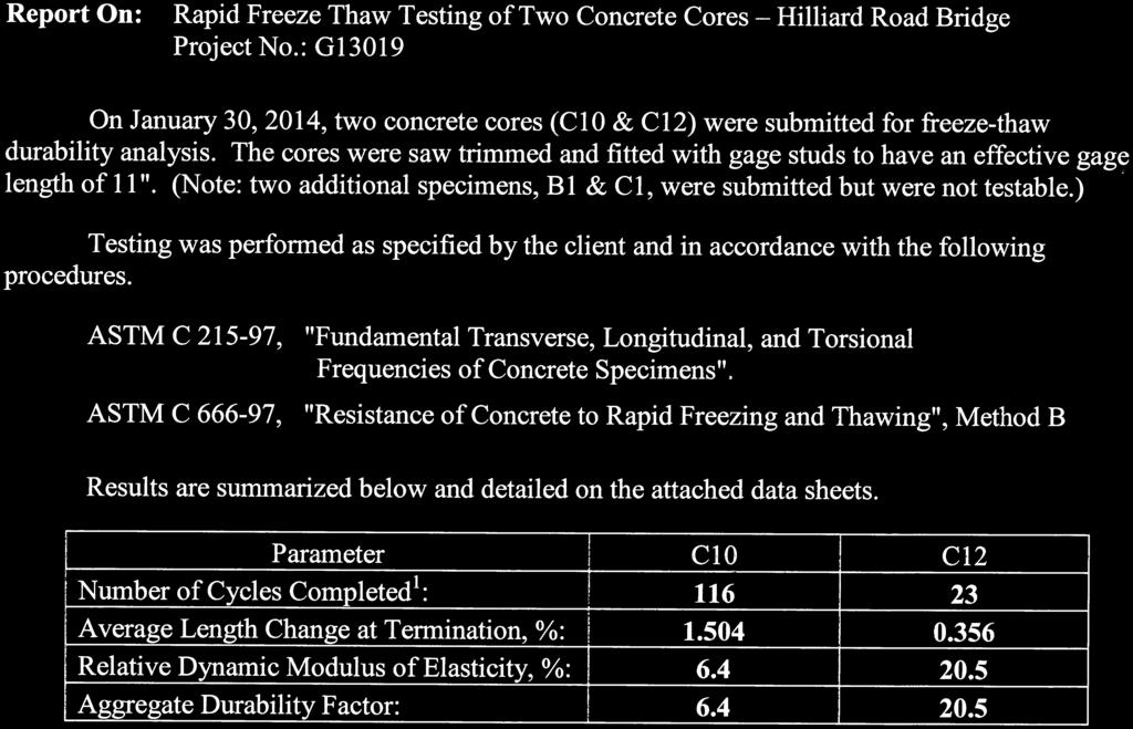
9 Hilliard Road Bridge Condition Assessment / Lakewood & Rocky River, Cuyahoga County, Ohio Page 6 sample C-03 contained a chloride content in excess of the ODOT maximum in both the shallow and deeper depths. Usually chloride contents of core samples are higher near the face of each core, as in the case of all of the cores tested. Refer to the attached Chloride Content Test Table for the chloride content test results found in the Appendix. 4.2 Compressive Strength Testing Compressive strength testing was performed on ten (10) of the structural core samples and two (2) of the bridge deck core samples obtained from this structure. Compressive strength testing was performed on the same core samples that Chloride Ion Content testing was performed. The compressive strength of the tested structural core samples ranged from 2,737 to 10,154 psi and the tested bridge deck core samples were 10,478 and 10,949 psi. Note that all of the core samples tested with the exception of C-01 exceeded 4,000 psi, which at present is generally considered the minimum strength standard for structural concrete. The compressive strength of the concrete core samples may or may not indicate potential strength problems at the tested locations. Refer to the Compressive Strength of Concrete Table found in the Appendix for the compressive strength test results. Upon completion of the laboratory testing, the remaining portions of the core samples will be discarded with the approval of TranSystems personnel. 4.3 Petrographic Analysis Petrographic Analysis was performed on two of the structural core samples (C-09 and C-11) by The Rock Doctor, Inc. Concrete Petrography. Based on The Rock Doctor report, core sample C-09 is deemed to be in fair general condition and core sample C-11 is deemed to be in poor-fair condition. The complete petrographic report prepared by The Rock Doctor, Inc. is included in the Appendix. 4.4 Freeze-thaw Freeze-thaw tests were performed on two (2) of the structural core samples; C-10 and C-12 by Bowser- Morner, Inc. Core samples C-01 and C-15 were also submitted for testing, however they were deemed nontestable. Core samples C-01 and C-15 were returned to PGI for compressive strength and chloride ion testing. The complete freeze-thaw report prepared by Bowser-Morner, Inc. is included in the appendix. Note that the testing was terminated early due to deterioration of the specimens. Pro Geotech, Inc. G13019Trpt/SS
10 Hilliard Road Bridge Condition Assessment / Lakewood & Rocky River, Cuyahoga County, Ohio Page LIMITATIONS This report is subject to the following conditions and limitations: 1. The results of the chloride ion, compressive strength, petrographic analysis, and freeze-thaw testing are indicative only of conditions at the tested locations of the core samples. Interpolation and correlation of these results to other locations within the structure should be performed by a qualified bridge engineer. Test results at specific locations may not be indicative of concrete conditions at similar locations throughout the structure. 2. It should be noted that the appearance and visual description of all concrete core samples in this report may vary from the actual condition of the cores. The actual condition of the concrete cores may be better determined by additional physical and/or chemical testing. 3. PGI personnel performed chloride ion content and compressive strength tests on twelve (12) core samples. Freeze-thaw testing on four (4) core samples, and petrographic analysis on two core samples was performed by others. These core samples may not be representative of the entire structure. It is possible that the actual condition of the structure may be better or worse than revealed by these core samples. The data contained in this report should be used in conjunction with a detailed visual inspection by a qualified bridge engineer. Design and rehabilitation recommendations should not be base solely on this report. Pro Geotech, Inc. G13019Trpt/SS
11 PROJECT No.: G13019T PROJECT: Hilliard Rd. Bridge Condition Assessment / COMPRESSIVE STRENGTH OF CONCRETE (ASTM C 39) CORE LENGTH DIAMETER DENSITY LOAD AT CORRECTION COMPRESSIVE TYPE OF NUMBER OF CORE OF CORE OF CORE FAILURE FACTOR STRENGTH FRACTURE* (in) (mm) (in) (mm) (pcf) (tons/cu.m) (lbs) (kg) (psi) (MPa) C C C C C C C C C C C C Pro Geotech, Inc E. Royalton Rd. Cleveland, OH Note: (1) Refer to locations in Appendix (2) 11 of 12 core tests pass the strength requirements as per ACI (3) * Refer to ASTM C-39.
12
13 PROJECT No.: G13019G PROJECT: Hilliard Rd. Bridge Condition Assessment / CHLORIDE CONTENT TEST (ASTM C-1152 / AASHTO T260) CORE DEPTH DENSITY CHLORIDE CHLORIDE NUMBER FROM FACE OF CORE CONTENT CONTENT (in) (mm) (lb/cu.ft) (tons/cu.m) (%) (lb/cu. yd) (kg/cu. m) C C C C C C C C C C C C C C C C C C C C C C C C Pro Geotech, Inc E. Royalton Rd. Cleveland, OH 44147
14
15 Core Location: C-01 CORE LOG Hilliard Road Bridge over Rocky River Core obtained from the south face of Pier No. 2 Project: Hilliard Rd. Bridge Condition Assessment / Date: Location: Lakewood & Rocky River, OH Core Type / Alignment: Client: TranSystems Coring Crew: Core Barrel Size (O.D.): 4.00" Hole Patched w/: 12/2/2013 Structure / Horizontal PGI - SP / DH Set 45 Non-shrink grout Photograph and Core Depth Description and Noted Features of Core Sample FACE OF THE CORE IS AT ZERO Cement matrix with subround to angular limestone aggregate with washed sand and gravel. The largest size aggregate is 1.5" in diameter. Few very small 0.5" Rebar and mechanical break during 9.0"; Mechanical break during removal. Total Core Recovery = 16.0" Abbreviations and Notes Note: Due to the angle at which the photographs were taken, the description to the right of the above core may appear to be slightly above or below the actual feature being described.
16 C-02 CORE LOG Core Location: Hilliard Road Bridge over Rocky River Core obtained from the north face of Arch Line A between Pier No. 2 and the west abutment. Project: Hilliard Rd. Bridge Condition Assessment / Date: 12/3/2013 Location: Lakewood & Rocky River, OH Core Type / Alignment: Structure / Horizontal Client: TranSystems Coring Crew: PGI - JR / MN Core Barrel Size (O.D.): 4.00" Hole Patched w/: Set 45 Non-shrink grout Photograph and Core Depth Description and Noted Features of Core Sample FACE OF THE CORE IS AT ZERO Cement matrix with subround to angular limestone aggregate with washed sand and gravel. The largest size aggregate is 1.25" in diameter. Few very small voids. Density of core = pcf Compressive strength = 5694 Mechanical break during removal. Total Core Recovery = 18.75" Abbreviations and Notes Note: Due to the angle at which the photographs were taken, the description to the right of the above core may appear to be slightly above or below the actual feature being described.

17 C-03 CORE LOG Core Location: Hilliard Road Bridge over Rocky River Core obtained from the north face of Arch Line C between Pier No. 2 and the west abutment. Project: Hilliard Rd. Bridge Condition Assessment / Date: 12/5/2013 Location: Lakewood & Rocky River, OH Core Type / Alignment: Structure / Horizontal Client: TranSystems Coring Crew: PGI - JR / MN Core Barrel Size (O.D.): 4.00" Hole Patched w/: Set 45 Non-shrink grout Photograph and Core Depth Description and Noted Features of Core Sample FACE OF THE CORE IS AT ZERO Cement matrix with subround to angular limestone aggregate with washed sand and gravel. The largest size aggregate is 2.0" in diameter. Few very small voids. Density of core = pcf Compressive strength = 7622 Mechanical break during removal. Total Core Recovery = 18.75" Abbreviations and Notes Note: Due to the angle at which the photographs were taken, the description to the right of the above core may appear to be slightly above or below the actual feature being described.
18 Core Location: C-04 CORE LOG Hilliard Road Bridge over Rocky River Core obtained from the south face of Arch Line D between Piers No. 1 and No. 2 Project: Hilliard Rd. Bridge Condition Assessment / Date: Location: Lakewood & Rocky River, OH Core Type / Alignment: Client: TranSystems Coring Crew: Core Barrel Size (O.D.): 4.00" Hole Patched w/: 12/4/2013 Structure / Horizontal PGI - JR / MN Set 45 Non-shrink grout Photograph and Core Depth Description and Noted Features of Core Sample FACE OF THE CORE IS AT ZERO Cement matrix with subround to angular limestone aggregate with washed sand and gravel. The largest size aggregate is 1.5" in diameter. Few very small voids. Minor surface fractures. Density of core = pcf Compressive strength = 5736 Mechanical break during removal. Total Core Recovery = 19.0" Abbreviations and Notes Note: Due to the angle at which the photographs were taken, the description to the right of the above core may appear to be slightly above or below the actual feature being described.
19 Core Location: C-05 CORE LOG Hilliard Road Bridge over Rocky River Core obtained from the north face of Arch Line B between Piers No. 1 and No. 2 Project: Hilliard Rd. Bridge Condition Assessment / Date: Location: Lakewood & Rocky River, OH Core Type / Alignment: Client: TranSystems Coring Crew: Core Barrel Size (O.D.): 4.00" Hole Patched w/: 12/4/2013 Structure / Horizontal PGI - JR / MN Set 45 Non-shrink grout Photograph and Core Depth Description and Noted Features of Core Sample FACE OF THE CORE IS AT ZERO Cement matrix with subround to angular limestone aggregate with washed sand and gravel. The largest size aggregate is 1.5" in diameter. Few very small voids. Density of core = pcf Compressive strength = 6232 Mechanical break during removal. Total Core Recovery = 20.0" Abbreviations and Notes Note: Due to the angle at which the photographs were taken, the description to the right of the above core may appear to be slightly above or below the actual feature being described.
20 Core Location: C-06 CORE LOG Hilliard Road Bridge over Rocky River Core obtained from the east face of the Floor Beam between Arch Lines C and D Project: Hilliard Rd. Bridge Condition Assessment / Date: Location: Lakewood & Rocky River, OH Core Type / Alignment: Client: TranSystems Coring Crew: Core Barrel Size (O.D.): 4.00" Hole Patched w/: 12/3/2013 Structure / Horizontal PGI - JR / MN Set 45 Non-shrink grout Photograph and Core Depth Description and Noted Features of Core Sample FACE OF THE CORE IS AT ZERO Cement matrix with subround to angular limestone aggregate with washed sand and gravel. The largest size aggregate is 1.5" in diameter. Few very small 0.5" Rebar Density of core = pcf Compressive strength = psi Total Core Recovery = 13.25" Abbreviations and Notes Note: Due to the angle at which the photographs were taken, the description to the right of the above core may appear to be slightly above or below the actual feature being described.
21 Core Location: C-07 CORE LOG Hilliard Road Bridge over Rocky River Core obtained from the west face of the Interior Jack Arch (Row 3) Project: Hilliard Rd. Bridge Condition Assessment / Date: Location: Lakewood & Rocky River, OH Core Type / Alignment: Client: TranSystems Coring Crew: Core Barrel Size (O.D.): 4.00" Hole Patched w/: 12/4/2013 Structure / Horizontal PGI - JR / MN Set 45 Non-shrink grout Photograph and Core Depth Description and Noted Features of Core Sample FACE OF THE CORE IS AT ZERO Cement matrix with subround to subangular limestone aggregate with washed sand and gravel. The largest size aggregate is 1.5" in diameter. Few very small voids. Density of core = pcf Compressive strength = 5068 Mechanical break during removal. Total Core Recovery = 19.25" Abbreviations and Notes Note: Due to the angle at which the photographs were taken, the description to the right of the above core may appear to be slightly above or below the actual feature being described.
22 C-08 CORE LOG Core Location: Hilliard Road Bridge over Rocky River Core obtained from the north face of the North Jack Arch (Row 1) north end and 8" from the top of the abutment. Project: Hilliard Rd. Bridge Condition Assessment / Date: 12/4/2013 Location: Lakewood & Rocky River, OH Core Type / Alignment: Structure / Horizontal Client: TranSystems Coring Crew: PGI - JR / MN Core Barrel Size (O.D.): 4.00" Hole Patched w/: Set 45 Non-shrink grout Photograph and Core Depth Description and Noted Features of Core Sample FACE OF THE CORE IS AT ZERO Cement matrix with round to angular limestone aggregate with washed sand and gravel. The largest size aggregate is 2.0" in diameter. Few very small voids. Density of core = pcf Compressive strength = 5836 Mechanical break during removal. Cored completely through the North Jack Arch Total Core Recovery = 18.0" Abbreviations and Notes Note: Due to the angle at which the photographs were taken, the description to the right of the above core may appear to be slightly above or below the actual feature being described.
23 C-09 CORE LOG Core Location: Hilliard Road Bridge over Rocky River Core obtained from the north face of Arch Line A between Pier No. 1 and the east abutment. Project: Hilliard Rd. Bridge Condition Assessment / Date: 12/3/2013 Location: Lakewood & Rocky River, OH Core Type / Alignment: Structure / Horizontal Client: TranSystems Coring Crew: PGI - JR / MN Core Barrel Size (O.D.): 4.00" Hole Patched w/: Set 45 Non-shrink grout Photograph and Core Depth Description and Noted Features of Core Sample FACE OF THE CORE IS AT ZERO Cement matrix with round to angular limestone aggregate with washed sand and gravel. The largest size aggregate is 1.25" in diameter. Few very small Mechanical break during removal. Total Core Recovery = 19.5" Abbreviations and Notes Note: Due to the angle at which the photographs were taken, the description to the right of the above core may appear to be slightly above or below the actual feature being described.

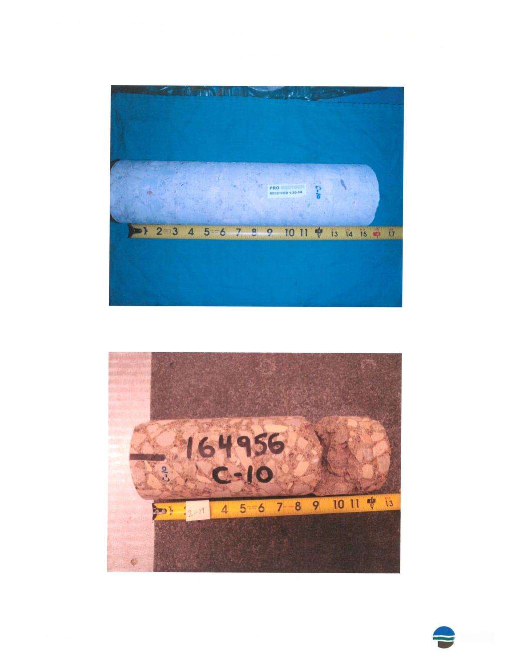
24 C-10 CORE LOG Core Location: Hilliard Road Bridge over Rocky River Core obtained from the south face of Arch Line C between Pier No. 1 and the east abutment. Project: Hilliard Rd. Bridge Condition Assessment / Date: 12/4/2013 Location: Lakewood & Rocky River, OH Core Type / Alignment: Structure / Horizontal Client: TranSystems Coring Crew: PGI - JR / MN Core Barrel Size (O.D.): 4.00" Hole Patched w/: Set 45 Non-shrink grout Photograph and Core Depth Description and Noted Features of Core Sample FACE OF THE CORE IS AT ZERO Cement matrix with subround to angular limestone aggregate with washed sand and gravel. The largest size aggregate is 1.25" in diameter. Few very small Mechanical break during removal. Total Core Recovery = 18.25" Abbreviations and Notes Note: Due to the angle at which the photographs were taken, the description to the right of the above core may appear to be slightly above or below the actual feature being described.
25 C-11 CORE LOG Core Location: Hilliard Road Bridge over Rocky River Core obtained from the north face of Arch Line B between Pier No. 1 and the east abutment. Project: Hilliard Rd. Bridge Condition Assessment / Date: 12/3/2013 Location: Lakewood & Rocky River, OH Core Type / Alignment: Structure / Horizontal Client: TranSystems Coring Crew: PGI - JR / MN Core Barrel Size (O.D.): 4.00" Hole Patched w/: Set 45 Non-shrink grout Photograph and Core Depth Description and Noted Features of Core Sample FACE OF THE CORE IS AT ZERO Cement matrix with subround to angular limestone aggregate with washed sand and gravel. The largest size aggregate is 1.75" in diameter. Few very small 0.5" Mechanical break during removal. Total Core Recovery = 20.5" Abbreviations and Notes Note: Due to the angle at which the photographs were taken, the description to the right of the above core may appear to be slightly above or below the actual feature being described.
: 4.")
26 Core Location: C-12 CORE LOG Hilliard Road Bridge over Rocky River Core obtained from the west face of the Floor Beam between Arch Lines A and B Project: Hilliard Rd. Bridge Condition Assessment / Date: Location: Lakewood & Rocky River, OH Core Type / Alignment: Client: TranSystems Coring Crew: Core Barrel Size (O.D.): 4.00" Hole Patched w/: 12/4/2013 Structure / Horizontal PGI - JR / MN Set 45 Non-shrink grout Photograph and Core Depth Description and Noted Features of Core Sample FACE OF THE CORE IS AT ZERO Cement matrix with round to angular limestone aggregate with washed sand and gravel. The largest size aggregate is 1.5" in diameter. Few very small Mechanical break during removal. Total Core Recovery = 18.5" Abbreviations and Notes Note: Due to the angle at which the photographs were taken, the description to the right of the above core may appear to be slightly above or below the actual feature being described.
27 Core Location: C-13 CORE LOG Hilliard Road Bridge over Rocky River Core obtained from the north face of Arch Line A between Pier No. 2 the west abutment Project: Hilliard Rd. Bridge Condition Assessment / Date: Location: Lakewood & Rocky River, OH Core Type / Alignment: Client: TranSystems Coring Crew: Core Barrel Size (O.D.): 4.00" Hole Patched w/: 12/4/2013 Structure / Horizontal PGI - JR / MN Set 45 Non-shrink grout Photograph and Core Depth Description and Noted Features of Core Sample FACE OF THE CORE IS AT ZERO Cement matrix with round to angular limestone aggregate with washed sand and gravel. The largest size aggregate is 1.5" in diameter. Few very small voids. Density of core = pcf Compressive strength = 5421 Mechanical break during removal. Total Core Recovery = 18.25" Abbreviations and Notes Note: Due to the angle at which the photographs were taken, the description to the right of the above core may appear to be slightly above or below the actual feature being described.

28 C-14 CORE LOG Core Location: Hilliard Road Bridge over Rocky River Core obtained from the south face of Arch Line D between Pier No. 2 and the west abutment. Project: Hilliard Rd. Bridge Condition Assessment / Date: 12/3/2013 Location: Lakewood & Rocky River, OH Core Type / Alignment: Structure / Horizontal Client: TranSystems Coring Crew: PGI - JR / MN Core Barrel Size (O.D.): 4.00" Hole Patched w/: Set 45 Non-shrink grout Photograph and Core Depth Description and Noted Features of Core Sample FACE OF THE CORE IS AT ZERO Cement matrix with round to angular limestone aggregate with washed sand and gravel. The largest size aggregate is 1.5" in diameter. Few very small 0.5" Rebar Density of core = pcf Compressive strength = 4150 Mechanical break during removal. Total Core Recovery = 16.75" Abbreviations and Notes Note: Due to the angle at which the photographs were taken, the description to the right of the above core may appear to be slightly above or below the actual feature being described.
29 Core Location: C-15 CORE LOG Hilliard Road Bridge over Rocky River Core obtained from the Bridge Deck Westbound Lane Project: Hilliard Rd. Bridge Condition Assessment / Date: Location: Lakewood & Rocky River, OH Core Type / Alignment: Client: TranSystems Coring Crew: Core Barrel Size (O.D.): 4.00" Hole Patched w/: 12/2/2013 Bridge Deck / Vertical PGI - SP / DH Set 45 Non-shrink grout Photograph and Core Depth Description and Noted Features of Core Sample FACE OF THE CORE IS AT ZERO 3.0" Overlay - Cement matrix with subround to angular limestone aggregate. The largest size aggregate is 0.5" in Mechanical break during removal. Cement matrix with subround to angular limestone aggregate with washed sand and gravel. The largest size aggregate is 1.5" in diameter. Few very small 6.0" and 10.0"; 0.75" Mechanical break during removal. Total Core Recovery = 12.75" Abbreviations and Notes Note: Due to the angle at which the photographs were taken, the description to the right of the above core may appear to be slightly above or below the actual feature being described.
30 Core Location: C-16 CORE LOG Hilliard Road Bridge over Rocky River Core obtained from the Bridge Deck Eastbound Lane Project: Hilliard Rd. Bridge Condition Assessment / Date: Location: Lakewood & Rocky River, OH Core Type / Alignment: Client: TranSystems Coring Crew: Core Barrel Size (O.D.): 4.00" Hole Patched w/: 12/2/2013 Bridge Deck / Vertical PGI - SP / DH Set 45 Non-shrink grout Photograph and Core Depth Description and Noted Features of Core Sample FACE OF THE CORE IS AT ZERO 3.5" Overlay - Cement matrix with subround to angular limestone aggregate. The largest size aggregate is 0.5" in Mechanical break during removal. Cement matrix with subround to angular limestone aggregate with washed sand and gravel. The largest size aggregate is 1.0" in 0.5" Rebar Few very small Mechanical break during removal. Density of core = pcf Compressive strength = " and 13.5"; 0.75" Rebar Total Core Recovery = 16.5" Abbreviations and Notes Note: Due to the angle at which the photographs were taken, the description to the right of the above core may appear to be slightly above or below the actual feature being described.
31 PETROGRAPHIC REPORT DATE: December 30, 2013 WORK ORDER: CLIENT: Pro Geotech, Inc. Project #: G13019G / Hillard Rd. Bridge PREPARED BY: Jeffrey R. Varga, Concrete Petrographer, The Rock Doctor, Inc. INTRODUCTION We received two, 4-inch diameter X 6 inch length, cores of hardened concrete to determine the general condition. The cores were marked C-9 and C-11 and exhibited saw-cut bottom surfaces. It was reported that the submitted core samples represent exterior concrete placed within bridge arch and pier portions. Deterioration of the bridge structure was reported. The age of the concrete(s) was reported to circa It was reported that core samples tested from similar structure units within the bridge averaged 4785 psi. SAMPLE PREPARATION AND METHODS The submitted core samples were cut approximately in half with cut surfaces oriented perpendicular to the end surfaces. One half of each core sample was prepared for examination. The respective cut surfaces were prepared by grinding and lapping using water and progressively finer abrasive materials following our standard procedure. The air-void system parameters were determined following the guidelines of ASTM C Standard Test Method for Microscopical Determination of Parameters of the Air-Void System in Hardened Concrete. The modified point count method was used at a magnification of 100 diameters. The prepared samples and sample trimmings were examined following the guidelines of ASTM C Standard Practice for Petrographic Examination of Hardened Concrete. RESULTS OF PETROGRAPHIC EXAMINATION CORE C-9 GENERAL CONDITION: (See PLATES 1-8) The exposed, top surface was generally flat and exhibited numerous, partially exposed fine aggregate particles and an almost continuous coating of light brown-dull white, semi-rigid material. This coating material exhibited numerous air-void septa and numerous fine cracks in thicker portions. The exposed surface was moderate-slowly water absorptive. A few coarser aggregate particles and small amounts of paste/mortar were observed where no coating material was present at the exposed surface. In section, the upper portion of the sample, approx. 3/8 of an inch up to approx. 1-1/4 inches, exhibited a markedly lighter colored (light brown) paste as compared to the bulk paste. After staining with Rainbow indicator (a blend of ph sensitive phenolphthaleins), these lighter colored portions exhibited redorange (ph of 5) to yellow (ph of 7) to green (ph of 9) colorations as compared to the purple (ph of 11+) CONFIDENTIAL PAGE 1 12/30/13
32 color of the bulk paste. The observed colorations of paste after staining indicate carbonation. These paste portions also effervesced more strongly as compared to the bulk paste when dilute hydrochloric acid was applied. However, the carbonated paste portions exhibited similar hardness as compared to the bulk paste. The observed surface coating material ranged in thickness form zero (non-existent) up to approx mm at thickest portions. One, vertically oriented, fine crack was observed perpendicular to the exposed surface up to an observed depth of 1/2 of an inch. This cracks transected paste only. Many, small to large, irregularly shaped voids were present throughout the sample especially adjacent to aggregate peripheries. Several of these voids appeared to be interconnected. The bottom surface was a saw-cut surface. The core edges exhibited several, large, irregularly shaped voids. CEMENTITIOUS MATRIX: The color of the cement paste matrix in the upper portion was previously described. The bulk paste exhibited mottled appearance with color ranging from light gray to dull white. Both upper and lower pastes exhibited a very small amount of unhydrated cement particles. Both pastes were highly water absorptive and moderately hard. No fly ash, ground granulated blast furnace slag or other pozzolanic materials were microscopically observed. AIR-VOID CONTENT: The air-void system parameters are listed below in TABLE 1: TABLE 1 AIR-VOID SYSTEM PARAMETERS TRAVERSE PARAMETERS OF THE AIR-VOID SYSTEM Paste % Length, Air, % l α L Sample by vol. Points in. by vol. P/A n in. in. -1 in. C , The observed voids were inhomogeneously distributed and were mostly irregularly shaped and ranged in size from small to large. Fewer, smaller spherically shaped were present. Several voids were interconnected. No secondary, internal deposits were observed. COARSE AGGREGATE: The homogeneously distributed coarse aggregate was angular to subangular in shape with an observed topsize of 1-1/8 of an inch. The observed aggregate was composed of dolomitic limestone particles. No marked evidence of a cement alkali:aggregate reaction was observed. FINE AGGREGATE: The homogeneously distributed fine aggregate was angular-rounded in shape and was composed of quartz, sandstones, siltstones, limestones, feldspars, granites, microcrystalline quartz cherts and mica flakes. Some of the observed siltstones were water absorptive. Although cherts are considered to be, at least, potentially reactive with cement alkalis, after three days of partial immersion of the sample trimming in water, no evidence of a cement alkali:aggregate reaction was observed. CORE C-11 GENERAL CONDITION: (See PLATES 1, 2, 9-15) The exposed, top surface was composed of an approx. half, rough, flat surface and approx. half of a worn surface exhibiting loss of surface up to approx. 1/8 of an inch. The generally flat, rough surface exhibited numerous, partially exposed fine aggregate particles in a soft, easily scratched, slightly recessed cement paste matrix. The worn surface exhibiting loss of surface CONFIDENTIAL PAGE 2 12/30/13
33 exhibited exhibited numerous, partially exposed fine aggregate particles and a few, fractured, water absorptive fine aggregate particles in a soft, easily scratched, recessed cement paste matrix. Very thin, small, remnant amounts of dull gray colored coating material were observed on both exposed surfaces especially on exposed fine aggregate particle peripheries and higher relief portions of the surfaces. This coating material exhibited a few air-void septa. The exposed surfaces were highly water absorptive. In section, a discontinuous zone of carbonated paste was observed from a veneer up to approx. 1-5/8 of an inch depth. After staining with Rainbow indicator (a blend of ph sensitive phenolphthaleins), these carbonated paste portions exhibited red-orange (ph of 5) to yellow (ph of 7) to green (ph of 9) colorations as compared to the purple (ph of 11+) color of the bulk paste. The observed colorations of paste after staining indicate carbonation. These paste portions also effervesced more strongly as compared to the bulk paste when dilute hydrochloric acid was applied. However, the carbonated paste portions exhibited similar hardness as compared to the bulk paste. Numerous, small to large, irregularly shaped voids were present throughout the sample especially adjacent to aggregate peripheries. Several of these voids appeared to be interconnected. The bottom surface was a saw-cut surface. The core edges exhibited many, large, irregularly shaped voids. CEMENTITIOUS MATRIX: The color of the cement paste matrix was variegated from light brown-dull white in color pale gray-gray. The paste exhibited a very small amount of unhydrated cement particles. The paste was highly water absorptive and moderately soft-moderately hard. No fly ash, ground granulated blast furnace slag or other pozzolanic materials were microscopically observed. AIR-VOID CONTENT: The air-void system parameters are listed below in TABLE 2: TABLE 2 AIR-VOID SYSTEM PARAMETERS TRAVERSE PARAMETERS OF THE AIR-VOID SYSTEM Paste % Length, Air, % l α L Sample by vol. Points in. by vol. P/A n in. in. -1 in. C , The observed voids were inhomogeneously distributed and were mostly irregularly shaped and ranged in size from small to large. Fewer, smaller spherically shaped were present. Several voids were interconnected. Many sinuously shaped voids were present as well. No secondary, internal deposits were observed. COARSE AGGREGATE: The homogeneously distributed coarse aggregate was angular to subangular in shape with an observed topsize of 1-3/4 of an inch. The observed aggregate was composed of dolomitic limestone particles. No marked evidence of a cement alkali:aggregate reaction was observed. FINE AGGREGATE: The homogeneously distributed fine aggregate was angular-rounded in shape and was composed of quartz, limestones, sandstones, siltstones, feldspars, microcrystalline quartz cherts and water absorptive iron claystone particles. Some of the observed siltstones were water absorptive. Although cherts are considered to be, at least, potentially reactive with cement alkalis, after three days of partial immersion of the sample trimming in water, no evidence of a cement alkali:aggregate reaction was observed. CONFIDENTIAL PAGE 3 12/30/13

, manufactured with durable aggregates,")
34 DISCUSSION We received two, 4-inch diameter X 6 inch length, cores of hardened concrete to determine the general condition. It was reported that the submitted core samples represent exterior concrete placed within bridge arch and pier portions. Deterioration of the bridge structure was reported. The age of the concrete(s) is unknown. No mix design, compressive strength testing results, placement details, etc. or other pertinent information was available as of this writing. According to ACI and PCA, durable concrete in a water saturated, cyclic freeze-thaw environment usually is air-entrained (air content of 3-7% by volume), manufactured with durable aggregates, exhibits a spacing factor, L, of inches or less, and attains an ultimate compressive strength of at least 4,000 psi. The examined samples were air-entrained however, the bulk of the voids were large and irregularly shaped. This strongly suggests that the samples were NOT intentionally air-entrained. The intended air content was unknown as of this writing. Overall, the aggregates appeared to be durable. The determined spacing factors ( and inches for Samples C-9 and C-11, respectively) was over the recommended industry standard limit of inches and are considered to be unacceptable for durability under water saturated, cyclic freeze-thaw conditions. Under similar exposure conditions, continued deterioration should be expected. It appears that Sample C-11 exhibited a higher degree of deterioration likely due to different exposure conditions. It should also be noted that Sample C-11 exhibited only remnants of coating material. The intended compressive strength of the concrete(s) represented by the samples and the actual compressive strengths of the in-place concrete(s) are unknown as of this writing. Carbonated paste portions were observed in both samples. However, the carbonated paste portions exhibited similar hardnesses as compared to the bulk pastes. All Portland cement based concretes will carbonate over time. The observed carbonation is likely a function of normal, expected carbonation over time. CONCLUSION Based on this examination, the general condition of Sample C-9 is deemed to be fair. The general condition of Sample C-11 is deemed to be poor-fair due to the greater degree of loss of surface and apparent higher degree of deterioration likely due to different exposure conditions. Both samples exhibited inadequate air-void systems that would predispose the concrete(s) to freeze-thaw distress in water-saturated, cyclic freezing environments. It must be noted that the intended compressive strength of the concrete(s) and the actual compressive strength of the in-place concrete are unknown as of this writing. J. R. Varga, Concrete Petrographer The Rock Doctor, Inc. CONFIDENTIAL PAGE 4 12/30/13
35 EXTERNAL RESOURCES American Concrete Institute ACI 201.2R-01 "Guide to Durable Concrete" CONFIDENTIAL PAGE 5 12/30/13
36

37
38 Summary of Results for the Freeze Thaw Tests Parameter C10 C12 Number of Cycles Completed 1: Average Length Change at Termination, %: Relative Dynamic Modulus of Elasticity, %: Aggregate Durability Factor: Average Length Change Many surrounding states have an expansion spec of 0.060% max. at 350 cycles. Both cores failed to pass the quality test for expansion 2. Relative Dynamic Modulus of Elasticity ODOT does not have a spec for Relative Dynamic Modulus nor for Durability Factor. Many USACE and FAA projects have a spec of at least >75% using C666 method A. The results of 6.4 and 20.5 scored way below the 75% target. Both cores fell apart during the test before reaching the 350 cycles intended. Based on information provided by the testing expert, the concrete core didn.t seem to be air entrained and the mortar base fell apart quickly

39


40


41
Geology 229 Engineering Geology. Lecture 7. Rocks and Concrete as Engineering Material (West, Ch. 6)
") Geology 229 Engineering Geology Lecture 7 Rocks and Concrete as Engineering Material (West, Ch. 6) Outline of this Lecture 1. Rock mass properties Weakness planes control rock mass strength; Rock textures;
Geology 229 Engineering Geology Lecture 7 Rocks and Concrete as Engineering Material (West, Ch. 6) Outline of this Lecture 1. Rock mass properties Weakness planes control rock mass strength; Rock textures;
CONCRETE IN THE MIDDLE EAST
 CONCRETE IN THE MIDDLE EAST ALKALI REACTIVITY IN CONCRETE STRUCTURES Presented by : Eng. ELIE J. SFEIR INTRODUCTION What is the Alkali-Reactivity? The alkali reaction is a chemical reaction between some
PERVIOUS CONCRETE EVALUATION MATERIALS INVESTIGATION DENVER, COLORADO
 PERVIOUS CONCRETE EVALUATION MATERIALS INVESTIGATION DENVER, COLORADO Prepared for: URBAN DRAINAGE AND FLOOD CONTROL DISTRICT 2480 West 26 th Avenue Suite #156-B Denver, Colorado Attention: Mr. Ken MacKenzie,
Engineer Research and Development Center. Petrographic Analysis of Portland Cement Concrete Cores from Pease Air National Guard Base, New Hampshire
 Petrographic Analysis of Portland Cement Concrete Cores from Pease Air National Guard Base, New Hampshire E. Rae Reed-Gore, Kyle L. Klaus, and Robert D. Moser November 2016 Engineer Research and Development
TESTING PROTOCAL. Via & US Mail. April 30, 2010
 Wiss, Janney, Elstner Associates, Inc. 330 Pfingsten Road Northbrook, Illinois 60062 847.272.7400 tel 847.291.5189 fax www.wje.com Via Email & US Mail General Manager 318 West Washington Street Valders
APPENDIX B DISTRESSES
 144 APPENDIX B DISTRESSES 145 INTRODUCTION The purpose of this appendix is not to provide a detailed discussion of the various descriptions and causes of distresses that may occur in any given pavement
Aggregates for Concrete
 Fine Aggregate Sand and/or crushed stone < 5 mm (0.2 in.) F.A. content usually 35% to 45% by mass or volume of total aggregate Coarse Aggregate Gravel and crushed stone 5 mm (0.2 in.) typically between
Louisiana Transportation Research Center
 Louisiana Transportation Research Center Technical Assistance Report 16-03TA-C Evaluation of Cores from Jefferson Highway Near Airline Highway by Tyson Rupnow, Ph.D., P.E. Amar Raghavendra, P.E. Zachary
Wikipedia.org BUILDING STONES. Chapter 4. Materials of Construction-Building Stones 1
 Wikipedia.org BUILDING STONES Chapter 4 Materials of Construction-Building Stones 1 What is Stone? Stone is a concretion of mineral matter. Used either as a; Construction material, Manufacture of other
EVALUATION OF GRAMPIAN SAND SANDSTONE
 14 September 2005 Sandstone Australia International 7 Disney Avenue KEILOR EAST VIC 3033 Attention: Mr. Harry Behncke EVALUATION OF GRAMPIAN SAND SANDSTONE CLIENT REFERENCE Request H. Behncke OUR REFERENCE
Sedimentary Rocks. Weathering. Mechanical & Chemical Weathering. Sediments. Lithification. Deposition. Transport. Erosion.
 Lithification Sedimentary Rocks Sediments Deposition Transport Erosion Weathering Weathering The sediments that make up sedimentary rocks are produced by: Mechanical & Chemical Weathering Mechanical Weathering
Civil Engineering, Surveying and Environmental Consulting WASP0059.ltr.JLS.Mich Ave Bridge Geotech.docx
 2365 Haggerty Road South * Canton, Michigan 48188 P: 734-397-3100 * F: 734-397-3131 * www.manniksmithgroup.com August 29, 2012 Mr. Richard Kent Washtenaw County Parks and Recreation Commission 2330 Platt
Geotechnical Engineering Report
 Geotechnical Engineering Report Turner Turnpike Widening Bridge D Bridge Crossing: South 209 th West Avenue Creek County, Oklahoma June 1, 2016 Terracon Project No. 04155197 Prepared for: Garver, LLC Tulsa,
Geotechnical Engineering Report
 Geotechnical Engineering Report Turner Turnpike Widening Bridge B Bridge Crossing: South 257 th West Avenue Creek County, Oklahoma June 1, 2016 Terracon Project No. 04155197 Prepared for: Garver, LLC Tulsa,
Coefficient of Thermal Expansion of Concrete Pavements
 Coefficient of Thermal Expansion of Concrete Pavements Erwin Kohler Ramon Alvarado David Jones University of California Pavement Research Center TRB Annual Meeting, Washington D.C. January 24 th, 2007
Geology 229 Engineering Geology. Lecture 6. Basic Rock Classification and Engineering Considerations (West, Chs. 2, 3, 4, 5)
") Geology 229 Engineering Geology Lecture 6 Basic Rock Classification and Engineering Considerations (West, Chs. 2, 3, 4, 5) Outline of this Lecture 1. Rock types and rock cycle 2. Geological and engineering
Geology 229 Engineering Geology Lecture 6 Basic Rock Classification and Engineering Considerations (West, Chs. 2, 3, 4, 5) Outline of this Lecture 1. Rock types and rock cycle 2. Geological and engineering
LEGEND ODOT CLASS. A-4b. A-6a. A-6b TOTAL VISUAL WEATHERED SANDSTONE VISUAL BORING LOCATION - PLAN VIEW
 PROJECT THE PROJECT CONSISTS IN PART OF ACING TWO STRUCTURES, EASTBOUND AND WESTBOUND STRUCTURES, RESPECTIVELY FOR THE PROPOSED SR OVER BLUE ROAD (CR 9). THE TWO STRUCTURES AS ANNED, ARE SINGLE-SPAN STRUCTURES
For Sale - 56 Acre Sandstone Quarry State Route 511, Oberlin/Kipton, OH 44075
 14647 State Route 511, Oberlin/Kipton, OH 44075 56 ACRES Vermilion Rd Gifford Rd Haigh Rd 44 Summary The Kipton sandstone quarry is included in 56 acre tract owned by Terry A. Johnson, of Huron, Ohio.
Ardaman & Associates, Inc. Geotechnical, Environmental and Materials Consultants
 SUBSURFACE SOIL EXPLORATION 42-INCH FORCE MAIN REPLACEMENT CHIQUITA BOULEVARD S AND SW 34 TH STREET CAPE CORAL, LEE COUNTY, FLORIDA Ardaman & Associates, Inc. Geotechnical, Environmental and Materials
New Developments in Correcting Rigid Pavement Pumping
 New Developments in Correcting Rigid Pavement Pumping F. H. G reen Research Engineer, Joint Highway Research Project Purdue University State and county highways have recently emerged from a five-year period
Basic Examination on Assessing Mechanical Properties of Concrete That Has Suffered Combined Deterioration from Fatigue and Frost Damage
 5th International Conference on Durability of Concrete Structures Jun 30 Jul 1, 2016 Shenzhen University, Shenzhen, Guangdong Province, P.R.China Basic Examination on Assessing Mechanical Properties of
2 Aggregates in Indiana
 2 Aggregates in Indiana Origin of Aggregates Gravel and Natural Sands Crushed Stone Slag Distribution of Aggregates Glacial Deposits Bedrock Deposits Aggregate Types Natural Aggregates Artificial Aggregates
B-1 BORE LOCATION PLAN. EXHIBIT Drawn By: 115G BROOKS VETERINARY CLINIC CITY BASE LANDING AND GOLIAD ROAD SAN ANTONIO, TEXAS.
 N B-1 SYMBOLS: Exploratory Boring Location Project Mngr: BORE LOCATION PLAN Project No. GK EXHIBIT Drawn By: 115G1063.02 GK Scale: Checked By: 1045 Central Parkway North, Suite 103 San Antonio, Texas 78232
Geotechnical Engineering Report
 Geotechnical Engineering Report Turner Turnpike Widening Polecat Creek Bridge (Bridge A) June 1, 2016 Terracon Project No. 04155197 Prepared for: Garver, LLC Prepared by: Terracon Consultants, Inc. TABLE
Outline. Introduction. Introduction Accident Damage. Introduction Act of God Damage NATIONAL HIGH PERFORMANCE CONCRETE FOLLOW UP SURVEY RESULTS BY:
 BY: NATIONAL FOLLOW UP SURVEY RESULTS Louis N. Triandafilou, P.E. FHWA Resource Center Baltimore Senior Structural Engineer CLAUDE S. NAPIER, Jr., P.E. FHWA Virginia Division Bridge Engineer Outline HPC
Engineering Geology. Igneous rocks. Hussien Al - deeky
 Igneous rocks Hussien Al - deeky 1 The Geology Definition of Rocks In Geology Rock is defined as the solid material forming the outer rocky shell or crust of the earth. There are three major groups of
Eight Years of Pulse Velocity Tests on Concrete Pavements in Kansas
 Eight Years of Pulse Velocity Tests on Concrete Pavements in Kansas RICHARD C. MEYER, Electronics Engineer, State Highway Commission of Xansas For the past eight years the Kansas Highway Commission has
Pavement Distress Categories
 Pavement Distress Identification Jointed Concrete Pavements Raymond Ong, Purdue University William Flora, INDOT Planning Joyce Stone, INDOT Pavement Engineering Samy Noureldin, INDOT Research Pavement
Effects of Basalt Fibres on Mechanical Properties of Concrete
 Effects of Basalt Fibres on Mechanical Properties of Concrete A. M. El-Gelani 1, C.M. High 2, S. H. Rizkalla 3 and E. A. Abdalla 4 1,4 University of Tripoli, Civil Engineering Department, Tripoli, Libya
METHOD OF TEST FOR RELATIVE DENSITY AND ABSORPTION OF FINE AGGREGATE
 Laboratory Testing Manual Date: 12 04 01 Page 1 of 10 METHOD OF TEST FOR RELATIVE DENSITY AND ABSORPTION OF FINE AGGREGATE 1. SCOPE 1.1 This method covers the determination of relative density (oven-dry
Unbound Pavement Applications of Excess Foundry System Sands: Subbase/Base Material
 Unbound Pavement Applications of Excess Foundry System Sands: Subbase/Base Material Tuncer B. Edil University of Wisconsin-Madison Recycled Materials Resource Center RMRC Participant Job Description Which
Geotechnical Data Report
 Geotechnical Data Report Downtown Greenville Future Conveyance Study December 1, 2015 Terracon Project No. 86155032 Prepared for: Prepared by: Terracon Consultants, Inc. December 1, 2015 561 Mauldin Road
Study of the performance of natural gravel of marginal soundness in concrete
 Concrete: Construction s Sustainable Option Cite this paper as follows: O Kelly B.C. 8. Study of the performance of natural gravel of marginal soundness in concrete. Proceedings of the Seventh International
Designation: NWI DIF Horizontal Hail impact Standard
 Designation: NWI DIF Horizontal Hail impact Standard 2.1.2015 Standard Test Method for Materials attached to Vertical or Near Vertical Surfaces and Their Resistance to Horizontally Propelled Freezer Ice
SEISMIC REFRACTION ANALYSIS OF EAST RIVER FLATS MINNEAPOLIS MINNESOTA A THESIS SUBMITTED TO THE FACULTY OF UNIVERSITY OF MINNESOTA AUTUMN HAAGSMA
 SEISMIC REFRACTION ANALYSIS OF EAST RIVER FLATS MINNEAPOLIS MINNESOTA A THESIS SUBMITTED TO THE FACULTY OF UNIVERSITY OF MINNESOTA BY AUTUMN HAAGSMA IN PARTIAL FULFILLMENT OF THE REQUIREMENTS FOR THE DEGREE
COMPOSITIONAL TERMS: FELSIC : light colored INTERMEDIATE : medium shades MAFIC : dark colored ULTRAMAFIC : rare (composition of the mantle)
") GEOLOGY 306 Laboratory NAME: Instructor: TERRY J. BOROUGHS SECTION: Common Rocks (Chapter 2) For this assignment, you will require: a streak plate, glass plate, magnet, dilute hydrochloric (HCl) acid,
GEOLOGY 306 Laboratory NAME: Instructor: TERRY J. BOROUGHS SECTION: Common Rocks (Chapter 2) For this assignment, you will require: a streak plate, glass plate, magnet, dilute hydrochloric (HCl) acid,
DATA REPORT GEOTECHNICAL INVESTIGATION GALVESTON CRUISE TERMINAL 2 GALVESTON, TEXAS
 DATA REPORT GEOTECHNICAL INVESTIGATION GALVESTON CRUISE TERMINAL 2 GALVESTON, TEXAS SUBMITTED TO PORT OF GALVESTON 123 ROSENBERG AVENUE, 8TH FLOOR GALVESTON, TEXAS 77553 BY HVJ ASSOCIATES, INC. HOUSTON,
CIVE 2700: Civil Engineering Materials Fall Lab 2: Concrete. Ayebabomo Dambo
 CIVE 2700: Civil Engineering Materials Fall 2017 Lab 2: Concrete Ayebabomo Dambo Lab Date: 7th November, 2017 CARLETON UNIVERSITY ABSTRACT Concrete is a versatile construction material used in bridges,
Geotechnical Engineering Study, Conifer Senior High School Football Field Improvements, Conifer, Colorado
 2390 South Lipan Street Denver, CO 80223 phone: (303) 742-9700 fax: (303) 742-9666 email: kadenver@kumarusa.com www.kumarusa.com Office Locations: Denver (HQ), Colorado Springs, Fort Collins, and Frisco,
CONCRETE TECHNOLOGY LABORATORY
 CONCRETE TECHNOLOGY LABORATORY DEPARTMENT OF CIVIL ENGINEERING CHULALONGKORN UNIVERSITY Tested by... ID No.... Date... Graded by... TEST No. C-7 NON-DESTRUCTIVE TEST OF HARDENED CONCRETE Part A Pulse Velocity
PROCIM. Developed by. Amirali Shojaeian Paolo Bocchini, Ph.D. Clay Naito, Ph.D., P.E. Liyang Ma Aman Karamlou John Fox, Ph.D.
 PENNDOT RESEARCH AGREEMENT E03134 TUTORIAL FOR PROBABILISTIC CHLORIDE INGRESS MODEL PROCIM FULL-PROBABILISTIC DESIGN TOOL Developed by Amirali Shojaeian Paolo Bocchini, Ph.D. Clay Naito, Ph.D., P.E. Liyang
NOA ASSESSMENT HARRIS QUARRY MENDOCINO COUNTY, CALIFORNIA TABLE OF CONTENTS
 NOA ASSESSMENT HARRIS QUARRY MENDOCINO COUNTY, CALIFORNIA TABLE OF CONTENTS Introduction... 1 Scope of Services... 1 Project Location and Description... 1 Geologic Setting... 1 Regional Geology... 1 Site
Aggregates. AAPA training
 Aggregates AAPA training Topics Aggregate sources and rock types Aggregate Production Aggregate Properties Coarse and fine aggregates in Asphalt Mixes Aggregates in Sprayed Seals Filler in asphalt mixes
TESTING of AGGREGATES for CONCRETE
 TESTING of AGGREGATES for CONCRETE The properties of the aggregates affect both the fresh and hardened properties of concrete. It is crucial to know the properties of the aggregates to be used in the making
Mechanistic Investigation of Granular Base and Subbase Materials A Saskatchewan Case Study
 Mechanistic Investigation of Granular Base and Subbase Materials A Saskatchewan Case Study Curtis Berthelot, P. Eng. Department of Civil and Geological Engineering University of Saskatchewan 57 Campus
2015 North Dakota Asphalt Conference
 2015 North Dakota Asphalt Conference NDDOT Implementation of AASHTO Flexible Pavement Design Part I ADT & ESALs Nickie Reis, P&AM Part II Structural Numbers Tom Bold, M&R March 31 - April 1, 2015 Part
SAND. By A S M Fahad Hossain Assistant Professor Department of Civil Engineering, AUST
 SAND By A S M Fahad Hossain Assistant Professor Department of Civil Engineering, AUST Definition Sand is a loose, fragmented, naturally-occurring material consisting of vary small particle (fine to medium
Lincoln County Board of Commissioner s Agenda Item Cover Sheet
 Lincoln County Board of Commissioner s Agenda Item Cover Sheet Board Meeting Date: Agenda Item Type: Consent Agenda: Public Hearing: Regular Agenda: Presentation Time (est): Submitting Person: Phone Number/Ext:
UNDP HARARE HOSPITAL PROPOSED NATPHARM WAREHOUSE
 UNDP HARARE HOSPITAL PROPOSED NATPHARM WAREHOUSE January 17 2016 TO CARRY OUT IN-SITU SOIL SURVEY, LABORATORY TESTS AND GEOTECHNICAL REPORTING. GEOTECHNICAL INVESTIGATIONS REPORT 1 2 Re: GEOTECHNICAL INVESTIGATIONS
Standard Test Method for Determination of the Point Load Strength Index of Rock 1
 Designation: D 5731 95 AMERICAN SOCIETY FOR TESTING AND MATERIALS 100 Barr Harbor Dr., West Conshohocken, PA 19428 Reprinted from the Annual Book of ASTM Standards. Copyright ASTM Standard Test Method
Classify Rock (rock1)
") Name: Date: 1. Cleavage of a mineral is related to a mineral's A. chemical composition. B. streak color. C. luster. D. crystalline structure. 2. Which is not part of the definition of a mineral? A. naturally
Name: Date: 1. Cleavage of a mineral is related to a mineral's A. chemical composition. B. streak color. C. luster. D. crystalline structure. 2. Which is not part of the definition of a mineral? A. naturally
Predicting Chloride Penetration Profile of Concrete Barrier in Low-Level Radwaste Disposal
 Predicting Chloride Penetration Profile of Concrete Barrier in Low-Level Radwaste Disposal Yu-Kuan Cheng*, I-Shuen Chiou, and Wei-Hsing Huang Department of Civil Engineering, National Central University
Chapter 2. The Ideal Aggregate. Aggregates
 Chapter 2 Aggregates The Ideal Aggregate Strong and resists loads applied Chemically inert so it is not broken down by reactions with substances it comes in contact with Has a stable volume so that it
Accelerated Loading Evaluation of Base & Sub-base Layers
 Accelerated Loading Evaluation of Base & Sub-base Layers Zhong Wu, Ph.D., P.E. Louisiana Transportation Research Center (LTRC) April 2006 What is Accelerated Loading? Accelerated loading refers to Accelerated
Modulus of Rubblized Concrete from Surface Wave Testing
 from Surface Wave Testing Nenad Gucunski Center for Advanced Infrastructure and Transportation (CAIT) Infrastructure Condition Monitoring Program (ICMP) 84 th Annual NESMEA Conference October 8, 2008 Route
APPENDIX B ABBREVIATIONS, SYMBOLS AND CONVERSION FACTORS Abbreviations
 APPENDIX B ABBREVIATIONS, SYMBOLS AND CONVERSION FACTORS Abbreviations A ampere AASHTO American Association of State Highway & Transportation Officials ABS (%) Percent of Absorbed Moisture Abs. Vol. Absolute
 UNIT DESCRIPTIONS: Artificial Fill, Undocumented (Afu): Locally derived sandy silt and silty sand, locally with clay and varying amounts of gravel and man-made debris. Abundant concrete rubble, in places
Mark B. Snyder, Ph.D., P.E., Engineering Consultant Bridgeville, Pennsylvania
 Mark B. Snyder, Ph.D., P.E., Engineering Consultant Bridgeville, Pennsylvania Prepared for presentation at the 2008 Minnesota Concrete Conference Continuing Education and Conference Center, St. Paul, MN
LEGEND ODOT CLASS A-3. A-3a. A-4a. A-6a. A-6b TOTAL VISUAL VISUAL VISUAL BORING LOCATION - PLAN VIEW
 PROJECT THE PROJECT CONSISTS IN PART OF CONSTRUCTING A SINGLE-SPAN BRIDGE ON RELOCATED SHUMWAY HOOW ROAD OVER THE CSXT RAILROAD. THE STRUCTURE AS ANNED, IS A SINGLE-SPAN STRUCTURE WITH MSE WAS AT THE ABUTMENTS.
Preferred practice on semi-integral abutment layout falls in the following order:
 GENERAL INFORMATION: This section of the chapter establishes the practices and requirements necessary for the design and detailing of semi-integral abutments. For general requirements and guidelines on
MICROSTRUCTURAL DEVELOPMENT IN FIRE DAMAGED CONCRETE - A CASE STUDY
 MICROSTRUCTURAL DEVELOPMENT IN FIRE DAMAGED CONCRETE - A CASE STUDY V P Chatterjee, S K Chaturvedi, S K Gupta, M Kumar and P S Sharma National Council for Cement and Building Materials, Ballabgarh, Haryana,
Semco Stone ASTM Stone Testing Results
 Semco Stone ASTM Stone Testing Results SEMCO HAS GONE SOCIAL! 1-800-814-1072 semcostone.com ASHRIDGE COLOR/CHARACTERISTICS: Ashridge Chopped is a Class III Quartzitic Sandstone that Is mostly blue/gray
APPENDIX H CONVERSION FACTORS
 APPENDIX H CONVERSION FACTORS A ampere American Association of State AASHTO Highway & Transportation Officials ABS (%) Percent of Absorbed Moisture Abs. Vol. Absolute Volume ACI American Concrete Institute
Evaluating Structural Performance of Base/Subbase Materials at the Louisiana Accelerated Pavement Research Facility
 Evaluating Structural Performance of Base/Subbase Materials at the Louisiana Accelerated Pavement Research Facility Zhong Wu, Ph.D., P.E. Zhongjie Zhang, Bill King Louay Mohammad Outline Background Objectives
Tension zone applications, i.e., cable trays and strut, pipe supports, fire sprinklers Seismic and wind loading
 General Information Mechanical Anchors General Information Power-Stud + SD1 Wedge Expansion Anchor Product Description The Power-Stud+ SD1 anchor is a fully threaded, torque-controlled, wedge expansion
CCR Rule Annual Inspection Report (cont.) 2
 2") The inspection findings consisted of maintenance items and items that were not observed to be signs or potential signs of significant structural weakness. No deficiencies or disrupting conditions that
The inspection findings consisted of maintenance items and items that were not observed to be signs or potential signs of significant structural weakness. No deficiencies or disrupting conditions that
Sedimentary Rocks. All sedimentary rocks begin to form when existing rocks are broken down into sediments Sediments are mainly weathered debris
 Rocks! Objectives Describe the major processes involved in the formation of sedimentary rock Distinguish between clastic sedimentary rocks and chemical sedimentary rocks Identify the features that are
Proposed Testing and Research Approach for Pyrrhotite-Induced Concrete Deterioration
 1 Proposed Testing and Research Approach for Pyrrhotite-Induced Concrete Deterioration Mr. Christopher M. Moore, Mr. Cody M. Strack, Dr. Robert D. Moser, Dr. Gordon W. McMahon, Engineer Research and Development
The Soniscope a Device for Field Testing of Concrete
 The Soniscope a Device for Field Testing of Concrete E. A. W hitehurst Research Engineer, Joint Highway Research Project Purdue University The determination of the quality of concrete in a structure or
R.M.HARW & ASSOCIATES LTD. GEOTECHNICAL INVESTIGATION PROPOSED BRIDGE SITE. HELAVA CREEKl MILE MACKENZIE HIGHWAY E-2510 OCTOBER 16, 1973
 El R.M.HARW & ASSOCIATES LTD. GEOTECHNICAL INVESTIGATION PROPOSED BRIDGE SITE HELAVA CREEKl MILE 616.4 MACKENZIE HIGHWAY E-2510 OCTOBER 16, 1973 R,M,HARDV & ASSOCIATES LTD. CONSULTING ENGINEERING & TESTING
FINAL REPORT GEOPHYSICAL INVESTIGATION WATER TOWER NO. 6 SITE PLANT CITY, FL
 APPENDIX B FINAL REPORT GEOPHYSICAL INVESTIGATION WATER TOWER NO. 6 SITE PLANT CITY, FL Prepared for Madrid Engineering Group, Inc. Bartow, FL Prepared by GeoView, Inc. St. Petersburg, FL February 28,
Construction aggregates : evaluation and specification Clive Mitchell Industrial Minerals Specialist
 Construction aggregates : evaluation and specification Clive Mitchell Industrial Minerals Specialist Outline of presentation Minerals at the British Geological Survey Particle size, shape & density Strength
GEOL Lab 9 (Carbonate Sedimentary Rocks in Hand Sample and Thin Section)
") GEOL 333 - Lab 9 (Carbonate Sedimentary Rocks in Hand Sample and Thin Section) Sedimentary Rock Classification - As we learned last week, sedimentary rock, which forms by accumulation and lithification
GEOL 333 - Lab 9 (Carbonate Sedimentary Rocks in Hand Sample and Thin Section) Sedimentary Rock Classification - As we learned last week, sedimentary rock, which forms by accumulation and lithification
APPENDIX F Development of Deicer-Modified Mortar Bar Test Method
 APPENDIX F Development of Deicer-Modified Mortar Bar Test Method Part I - Assessing Potential Reactivity of Aggregates in Presence of Potassium Acetate Deicer Revised EB-70 Test Method Part II Evaluation
STRUCTURAL STABILITY ASSESSMENT
 STRUCTURAL STABILITY ASSESSMENT CFR 257.73(d) Bottom Ash Pond Complex Cardinal Plant Brilliant, Ohio October, 2016 Prepared for: Cardinal Operating Company Cardinal Plant Brilliant, Ohio Prepared by: Geotechnical
Alkali-Silica Reaction In Concrete
 Alkali-Silica Reaction In Concrete By KAUSHAL KISHORE Materials Engineer, Roorkee The problem of Alkali-silica reaction was believed to be non-existent in India till 1983, when its occurrence was diagnosed
Geology 229 Engineering and Environmental Geology. Lecture 5. Engineering Properties of Rocks (West, Ch. 6)
") Geology 229 Engineering and Environmental Geology Lecture 5 Engineering Properties of Rocks (West, Ch. 6) Outline of this Lecture 1. Triaxial rock mechanics test Mohr circle Combination of Coulomb shear
Geology 229 Engineering and Environmental Geology Lecture 5 Engineering Properties of Rocks (West, Ch. 6) Outline of this Lecture 1. Triaxial rock mechanics test Mohr circle Combination of Coulomb shear
COMPARING LABORATORY AND FIELD DURABILITY TESTING OF STONE Accelerated Weathering Testing of Stone
 COMPARING LABORATORY AND FIELD DURABILITY TESTING OF STONE Accelerated Weathering Testing of Stone B. WONNEBERGER AND S. A. BORTZ Wiss, Janney, Elstner Associates, Inc., Northbrook, Illinois, USA 60062
Impact of Existing Pavement on Jointed Plain Concrete Overlay Design and Performance
 Impact of Existing Pavement on Jointed Plain Concrete Overlay Design and Performance Michael I. Darter, Jag Mallela, and Leslie Titus-Glover 1 ABSTRACT Concrete overlays are increasingly being constructed
Experimental Study on Durability and Mechanical Properties of Basalt Fiber Reinforced Concrete under Sodium Sulfate Erosion
 961 A publication of CHEMICAL ENGINEERING TRANSACTIONS VOL. 62, 2017 Guest Editors: Fei Song, Haibo Wang, Fang He Copyright 2017, AIDIC Servizi S.r.l. ISBN 978-88-95608-60-0; ISSN 2283-9216 The Italian
 SOIL CLASSIFICATION CHART COARSE-GRAINED SOILS MORE THAN 50% RETAINED ON NO.200 SIEVE FINE-GRAINED SOILS 50% OR MORE PASSES THE NO.200 SIEVE PRIMARY DIVISIONS GRAVELS MORE THAN 50% OF COARSE FRACTION RETAINED
Construction Exits Rock pads
 Construction Exits Rock pads SEDIMENT CONTROL TECHNIQUE Type 1 System Sheet Flow Sandy Soils Type 2 System Concentrated Flow [1] Clayey Soils Type 3 System Supplementary Trap Dispersive Soils [1] Minor
POLITECNICO DI TORINO
 Dipartimento di Ingegneria del Territorio, dell Ambiente e delle Geotecnologie April, 11 2007 The Scientific Coordinator: (Dott. Paola Marini) REPORT LM/KP_04/07in REPORT ON DETERMINATION OF PHYSICAL AND
ALUMINUM STRUCTURAL PLATE HEADWALLS AASHTO LRFD BASIS OF DESIGN
 ALUMINUM STRUCTURAL PLATE EADWALLS AASTO LRFD BASIS OF DESIGN LANE ENTERPRISES, INC. www.lane-enterprises.com Required Backfill and Load Cases: ALUMINUM STRUCTURAL PLATE EADWALLS BASIS OF DESIGN Backfill
LECTURE NO. 4-5 INTRODUCTION ULTRASONIC * PULSE VELOCITY METHODS
 LECTURE NO. 4-5 ULTRASONIC * PULSE VELOCITY METHODS Objectives: To introduce the UPV methods To briefly explain the theory of pulse propagation through concrete To explain equipments, procedures, calibrations,
Design of RC Retaining Walls
 Lecture - 09 Design of RC Retaining Walls By: Prof Dr. Qaisar Ali Civil Engineering Department UET Peshawar www.drqaisarali.com 1 Topics Retaining Walls Terms Related to Retaining Walls Types of Retaining
Standard Test Method for Flat Particles, Elongated Particles, or Flat and Elongated Particles in Coarse Aggregate 1
 Designation: D479 0 Standard Test Method for Flat Particles, Elongated Particles, or Flat and Elongated Particles in Coarse Aggregate This standard is issued under the fixed designation D479; the number
PERFORMANCE ANALYSIS OF WELCH PRODUCTS RECYCLED RUBBER SPACER BLOCK
 PERFORMANCE ANALYSIS OF WELCH PRODUCTS RECYCLED RUBBER SPACER BLOCK Submitted by Bob W. Bielenberg, M.S.M.E., E.I.T. Research Associate Engineer Ronald K. Faller, Ph.D., P.E. Research Assistant Professor
DIVISION: METALS SECTION: METAL FASTENINGS SECTION: STEEL DECKING REPORT HOLDER: PNEUTEK, INC.
 ICC ES Report ICC ES () 7 () www.icc es.org Most Widely Accepted and Trusted ESR 1 Reissued /1 This report is subject to renewal /. DIVISION: METALS SECTION: METAL FASTENINGS SECTION: 1 STEEL ING REPORT
REPORT ON THE ASSESSMENT OF TRENCHING INTHE ROAD RESERVE OF THE ROAD BETWEEN BEAUFORT WEST AND CARNAVON.
 Contract Report CSIR/BE/TIE/SKA/59E2214 August 2018 REPORT ON THE ASSESSMENT OF TRENCHING INTHE ROAD RESERVE OF THE ROAD BETWEEN BEAUFORT WEST AND CARNAVON. Authors: Dave Ventura Anele Sambo Michael Roux
Mar 1, 2018 LAB MANUAL INDEX 1. Table of Contents Laboratory Testing Methods Reducing Aggregate Field Samples to Testing Size (Ver.
 Mar 1, 2018 LAB MANUAL INDEX 1 Table of Contents Laboratory Testing Methods 1000 Standard Practices (Ver. Sep 23, 2014) 1001 Receiving and Identifying Samples (Ver. Mar 1, 2018) 1002 Reducing Aggregate
Coating Requirements for Pipelines Installed by Horizontal Directional Drilling John D. Hair, P.E.*
 Coating Requirements for Pipelines Installed by Horizontal Directional Drilling John D. Hair, P.E.* *President, J. D. Hair & Associates, Inc., 2121 South Columbia Avenue, Suite 101, Tulsa, OK 74114-3502;
RIPRAP ASSESSMENT VARIOUS SITES HWY 40 NEAR GRANDE CACHE, AB
 RIPRAP ASSESSMENT VARIOUS SITES HWY 40 NEAR GRANDE CACHE, AB Need for Riprap Increased traffic along Hwy 40 has generated a lot of construction projects to upgrade highway Lack of good quality heavy rock
CITY OF BEAVER DAM SNOW & ICE REMOVAL POLICY
 CITY OF BEAVER DAM SNOW & ICE REMOVAL POLICY Revised January, 2016 Approved by Operations Committee: February 1, 2016 This snow and ice removal policy guides Public Works personnel with deicing, plowing,
NHBRA SOIL LABORATORY SECTION INTERIM REVISED TEST RATES FOR THE MATERIALS LABORATORY
 NHBRA SOIL LABORATORY SECTION INTERIM REVISED TEST RATES FOR THE MATERIALS LABORATORY DATE OF REVISION: ) 10th October 2010 S/N TEST DESCRIPTION UNIT RATE REMARKS 1 Sieve Analysis (wet and dry methods
ENVIRONMENTAL EFFECTS OF EARLY AGE AND LONG TERM RESPONSE OF PCC PAVEMENT
 ENVIRONMENTAL EFFECTS OF EARLY AGE AND LONG TERM RESPONSE OF PCC PAVEMENT Luis Julian Bendana, Engineering Res Specialist I New York State DOT Jason Wise, Graduate Student Ohio University ABSTRACT Early
DIVISION OF MINERAL RESOURCES JAMES L. CALVER, COMMISSIONER WATER WELL COMPLETION REPORT
 MAILING ADDRESS, Bc 3667 C. Jiottesville, VA 22903 COMMONWEALTH OF VIRGI N IA DEPARTMENT OF CONSERVATION AND ECONOMIC DEVELOPMENT DIVISION OF MINERAL RESOURCES JAMES L. CALVER, COMMISSIONER WATER WELL
TABLE 3-7. RECOMMENDED EQUWALENCY FACTOR RANGES FOR STABILIZED SUBBASE. Eauivalencv Factor Range
 AC150/5320-6D 7l7l95 C. Stabilized Subbase. Stabilized subbases also offer considerably higher strength to the pavement than P4. Recommended equivalency factors associated with stabilized subbase are presented
Hydrogeological Assessment for Part of Lots 2 and 3, Concession 5, Township of Thurlow, County of Hastings 1.0 INTRODUCTION. 1.
 February 10,2017 25506400 Ontario Ltd. Foxboro, ON Attention: Brad Newbatt Re: Hydrogeological Assessment for Part of Lots 2 and 3, Concession 5, Township of Thurlow, County of Hastings 1.0 INTRODUCTION