Research Article Plasma-Based Surface Modification of Polydimethylsiloxane for PDMS-PDMS Molding
|
|
|
- Bruce McGee
- 6 years ago
- Views:
Transcription
1 International Scholarly Research Network ISRN Polymer Science Volume 212, Article ID , 5 pages doi:1.542/212/ Research Article Plasma-Based Surface Modification of Polydimethylsiloxane for PDMS-PDMS Molding S.LoperaandR.D.Mansano Laboratório de Sistemas Integráveis,Escola PolitécnicaUniversityda São Paulo, São Paulo 558-1, SP, Brazil Correspondence should be addressed to S. Lopera, slopera@lsi.usp.br Received 5 January 212; Accepted 6 February 212 Academic Editors: M. Patel and D. Pavel Copyright 212 S. Lopera and R. D. Mansano. This is an open access article distributed under the Creative Commons Attribution License, which permits unrestricted use, distribution, and reproduction in any medium, provided the original work is properly cited. We present and compare two processes for plasma-based surface modification of Polydimethylsiloxane (PDMS) to achieve the antisticking behavior needed for PDMS-PDMS molding. The studied processes were oxygen plasma activation for vapor phase silanization and plasma polymerization with tetrafluoromethane/hydrogen mixtures under different processing conditions. We analyzed topography changes of the treated surfaces by atomic force microscopy and contact angle measurements. Plasma treatment were conducted in a parallel plate reactive ion etching reactor at a pressure of 3 mtorr, 3 Watts of RF power and a total flow rate of 3 sccm of a gas mixture. We found for both processes that short, low power, treatments are better to create long-term modifications of the chemistry of the polymer surface while longer processes or thicker films tend to degrade faster with the use leaving rough surfaces with higher adherence to the molded material. 1. Introduction As reviewed by Macdonald and Whitesides [1], PDMS (polydimethylsiloxane) has proven to be a suitable material for microfluidic device fabrication. It is optically transparent and can be molded to reproduce structures down to nanoscale resolution [2, 3], usually by direct casting on photoresist features over silicon wafers. SU8 is the most commonly used photoresist for master fabrication; single- or multilevel SU8 lines and structures have been extendedly used for PDMS microchannel definition, however, reutilization of resist masters is limited due to degradation by thermal stress during the curing process and by demolding forces. Some strategies such as coatings with diamond-like carbon (DLC) and DLC-polymer hybrids can be applied to increase the durability of the molds [4]. In this paper we present an improved method to replace the use of conventional photoresist masters with more durable positive copies in PDMS. Due to its elasticity, flexible masters in PDMS are not affected by thermal stress during the heating-cooling cycles of the curing process and it is easier to achieve a conformal contact between mold and countermold in closed molding configurations for the production of parts with through holes. Similar methods have been presented to mold complex 3D structures with through holes: Lucas et al. in 28 [5] presented the use of flexible molds made with freestanding SU8 layers for double-side molding of PDMS, Jo et al. in 2 [6] used a plastic sheet as countermold for SU8 molds and Janelle et al. in 2 [7] presented the use of slabs of PDMS treated with threetridecafluorotetrahydrooctyl-trichlorosilane as countermolds. Here we explore two plasma processes for surface modification of PDMS to achieve the antisticking behavior needed for PDMS-PDMS molding. For this application, three main characteristics are needed from the plasma treatment: the peeling force required to demold the PDMS parts off the treated molds should be low, the surface roughness of the mold should not be considerably increased, and the antisticking effect should be permanent and stable over the time. 2. Materials and Methods 2.1. Sample Preparation. We prepared PDMS samples using Sylgard 184 from Dow Corning, mixed in 1 : 1 proportion of curing agent to base polymer, degassed in vacuum for
2 2 ISRN Polymer Science Table 1: Recipes for photolithography (SU8-25). Thickness Spinning Before bake Exp. dose After bake Developing 5 µm 3 RPM min 6 mj cm min 5min 3 µm 5 RPM 95 4 hours 36 mj cm min 3 min 3 min and oven baked at 1 C for 3 minutes after casting over silicon wafers. We prepared also PDMS samples with rough surfaces, by casting on the rear face of a silicon wafer to increase the contact area for adhesion tests. All PDMS pieces were cast with a thickness of approximately 2 mm, cut in 2 cm 2 cm squares and plasma bonded to 1 3 glass slides for easy handling. The samples were rinsed with distilled water, sonicated in isopropyl alcohol for 5 minutes, and rinsed again in distilled water to remove particles prior to the treatments. Contact angle ( ) Ref 5 min 1 min 15 min Process time 2.2. Fluorinated Plasma Treatments. This treatment consists in a plasma polymerization of fluorinate compounds over the PDMS surface using CF 4 /H 2 mixtures. Two different CF 4 /H 2 proportions were studied: 5% hydrogen and 2% hydrogen with process times of 1, 5, and 1 minutes. Fluorinated plasma treatments were conducted in a parallel plate RIE reactor at a pressure of 3 mtorr, 3 Watts of RF power (13.56 MHz), and a total flow rate of 3 sccm of the desired gas mixture Plasma-Activated Silanization. The second method consists in an oxygen plasma activation of the PDMS surface to promote de incorporation of Hexamethyldisiloxane molecules. PDMS samples were plasma oxidized in a remote plasma reactor to avoid direct bombardment of the surface. This reactor is composed by a 1 quartz tube, 2 cm long, with an oxygen inlet at one end connected to a vacuum chamber containing the samples at the other end. High DC voltage is applied between the ends to produce a glow discharge at 3 mtorr 18 W of DC power for 5 seconds and placed on a hotplate at 1 C with two drops of HMDS, covered with a 6 Petri dish immediately afterward Surface Topography and Adhesion to PDMS. The surface topography of the processed samples was analyzed by atomic force microscopy using a NanoSurf Nanite AFM. We did also contact angle measurements with a simple imaging setup and using the low-bond axisymmetric drop shape analysis (LB- ADSA) script for Image J developed by Stalder et al. [8]. The adhesive forces of the different treated surfaces to the PDMS were qualitatively compared by manual pealing straps of PDMS cured over each sample, ordering form low to high the force required to peal the PDMS apart. The surface interactions with PDMS were also studied by atomic force spectroscopy (AFS), with a contact-mode AFM tip (NanoWorld CNTR-1) coated with PDMS Flexible Molds Fabrication. To illustrate the application of the studied antisticking treatments for the fabrication of flexible PDMS copies of micromolds, we fabricated two level Contact angle ( ) % H 2 2% H 2 Ref As treated Rinsed Hydrogen (%) Figure 1: Contact angle of PDMS samples treated with CF 4 /H 2 under different conditions. SU8 masters onto 3 glass wafers by using high resolution photoplotted sheet as a mask. The first layerwas5µm thick, to define channels and the second layer 3 µm thick for interconnection posts. Table 1 summarizes the lithographic recipes for each layer. The flexible molds are obtained in a two steps process, first we use the SU8/silicon mold to cast a PDMS inverted copy that is then treated with the selected antisticking plasma process and used to cast the positive copy in PDMS that is also plasma treated for further use. 3. Results and Discussion 3.1. Contact Angle Measurements. In a preliminary study we had observed that the contact angle of the PDMS samples to water decreases with the plasma processing time and with the hydrogen percentage in the gas mixture, as shown in Figure 1, but the hydrophobicity of the samples is partially recovered after rinsing with water.


3 ISRN Polymer Science 3 Contact angle ( ) Ref 1 min 5 min 1 min Process time PDMS 2% H 2 PDMS 5% H 2 Glass 2% H 2 Glass 5% H 2 Figure 2: Contact angle of PDMS and glass samples processed with CF 4 /H 2 plasmas at 3 mtorr 3 W. The hydrophilic behaviour of the treated samples can be explained by three possible factors: an increment in the surface roughness, the polymerization of a less hydrophobic film on the surface, or the production of polar or charged terminations in the PDMS chains. As the surfaces became again hydrophobic after rinsing with water it is plausible that instable polar groups be primarily responsible for the measured low contact angles and this groups are removed by the dipole interactions with the water. The curves in Figure 2 correspond to the contact angles measured on PDMS and glass of the treated samples after rinsing for 1 minutes with IPA and water to remove nonbonded compounds. On glass, the fluorinated plasma treatment has the effect of increasing the contact angle while on PDMS the treatment decreases the contact angle what indicates that the deposited polymer has an intermediate contact angle around 9. The results of both treatment with 5% hydrogen and 2% hydrogen are similar on glass but very dissimilar on the PDMS, this occurs by the depletion of fluorine ions by the etching reactions with the glass that increase locally the relative proportion of hydrogen, getting close to the saturation of polymerization rate observed after 2% of hydrogen. Comparing the evolution of the contact angle of the as treated samples with the process time (Figure 1) and the same for samples after rinsing with IPA (Figure 2), it is evident that the rinsing process degrades somehow the polymerized film, recovering partially the original contact angle value of the original substrate. From Figure 2 it is also noted that thicker films, deposited with 2% hydrogen and longer times, are more affected by the rinsing process and that the adherence of the fluorinated polymer to the glass substrates seems to be stronger than the adherence to PDMS substrates Antisticking Behavior. All the studied treatments conferred to the PDMS in major or minor degree the desired antisticking effect and it was possible to classify from low to high the peeling force required to manually lift with tweezers a 2 µ L drop of PDMS cured on each treated surface. Seven Pull off Jump (nm) Deflection (nm) Z axis (µm) 5% 1 min 2% 1 min 5% 1 min HMDS 2% 1 min (a) 5%-1 min 5%-5 min 5%-1 min 2%-1 min 2%-5 min 2%-1 min HMDS Treatment (b) Figure 3: Atomic force spectroscopy curves (a) and AFS pull-off jump (b). samples corresponding to two CF 4 /H 2 proportions for three processing times plus the silanized PDMS sample were then indexed from 1 to 7 according to the qualitative comparison made by two experimenters in three independent repetitions. The atomic force spectrograms of the samples exhibited different pull-off jumps between treatments and also different point to point variability within each sample. In Figure 3 we plotted the different AFS spectrograms. It was expected that the pull-off jump, which is the maximum negative deflection of the AFM cantilever before it loses contact with the sample in the backward part of the AFS cycle, would be proportional to the adhesive force of the PDMS to the treated surface, however when we plotted together the 1 7 index of the peeling force and the AFS data of the seven samples the results were completely inverse; the graph in Figure 4 at the right shows this superimposed data plots where the lower pull off jump corresponded to the higher peeling force and vice versa. This apparent inconsistency could be related to the surface roughness that can affect the effective contact area between the coated tip and the sample; if the surface of a sample is so rough that only a few peaks of its topography Peeling force index
")


.")


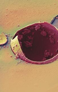
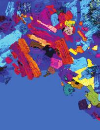
4 4 ISRN Polymer Science Ra: 31.4 nm Ra: 26.2 nm Line fit 575 nm Line fit 754 nm Silanized surface (HMDS) Un-treated PDMS reference Ra: 34.9 nm Line fit 565 nm Ra: 28.9 nm Line fit 754 nm 1 1 min of CF4 + 2% 1 min of CF4 + 2% Figure 4: AFM images of the PDMS samples: untreated PDMS reference, silanized surface, and CF4 + 2% H2 for 1 and 1 minutes. Figure 5: SU8 mold (left), negative copy in PDMS (center), and positive copy (right). touch the coated AFM tip then the measured pull of force will be low, but on the contrary the effective contact area with a PDMS drop cured on it will be higher requiring a bigger force to peel it off. The samples with higher variability that correspond to the lower pull off forces are also the samples with thicker polymerized films (2% hydrogen, 5 and 1 min) that appeared to be degraded during the rinsing, this reaffirms
5 ISRN Polymer Science 5 that in some places the film could be away giving different measurements from point to point. The AFM images of the surface topography can give more information on this topic Surface Topography. In Figure 4 we present the AFM images of some treated surfaces and the untreated PDMS reference. The three samples processed with 5% hydrogen and the sample for one minute process with 2% hydrogen showed a surface quality similar to the untreated reference, all of them remained optically clear with a slight increase in roughness; only the samples with longer treatments for higher hydrogen concentration produced thicker brown films that led to a rough texture after rinsing. These results are consistent with the previous observations of AFS and contact angle measurements, indicating that thinner films are more stable than thicker films. The HMDS silanization formed a cracked-like texture on the samples but with a low main roughness. Comparing all the studied treatments we found very similar results for 1 minute CF 4 + 2% hydrogen and 1 minutes CF 4 + 5% hydrogen what could be associated with a similar film thickness, both having low peeling forces, low roughness and the higher measured AFS pull-off jump. The silanization process showed also similar AFS values and a low peeling force, however, with a characteristic texture that could be problematic for some applications. proteins, Microelectronic Engineering, vol. 86, no. 4-6, pp , 29. [4] M. Okada, M. Iwasa, K. I. Nakamatsu et al., Evaluation of fluorinated diamond like carbon as antisticking layer by scanning probe microscopy, Photopolymer Science and Technology, vol. 21, no. 4, pp , 28. [5] N. Lucas, S. Demming, A. Jordan, P. Sichler, and S. Büttgenbach, An improved method for double-sided moulding of PDMS, Micromechanics and Microengineering, vol. 18, no. 7, Article ID 7537, 28. [6]B.H.Jo,L.M.VanLerberghe,K.M.Motsegood,andD.J. Beebe, Three-dimensional micro-channel fabrication in polydimethylsiloxane (PDMS) elastomer, Microelectromechanical Systems, vol. 9, no. 1, pp , 2. [7]R.A.Janelle,D.T.Chiu,R.J.Jackmanetal., Fabricationof topologically complex three-dimensional microfluidic systems in PDMS by rapid prototyping, Analytical Chemistry, vol. 72, no. 14, pp , 2. [8] A.F.Stalder,T.Melchior,M.Müller, D. Sage, T. Blu, and M. Unser, Low-bond axisymmetric drop shape analysis for surface tension and contact angle measurements of sessile drops, Colloids and Surfaces, A, vol. 364, no. 1 3, pp , PDMS-PMDS Molding. In Figure 5 we present optical and electronic micrographs of a micromold and its negative and positive copies obtained in PDMS with the proposed replication technique. Demolding PDMS parts from this flexible copies was found to be even easier that from the original SU8 Mold. 4. Conclusion All studied treatments achieved the desired antisticking effect on PDMS surfaces, however long plasma treatments increase the surface roughness and create thicker films that are delaminated by rinsing or demolding forces losing its effect. The best results were obtained with 1 min treatment CF 4 + 2% H 2, 1 min treatment CF 4 +5%H 2, and plasma-activated silanization, all of them requiring low peeling forces and having a good surface quality. We demonstrated the applicability of the developed method for the fabrication of flexible copies of SU8 masters for microfluidics. References [1] J. C. McDonald and G. M. Whitesides, Poly(dimethylsiloxane) as a material for fabricating microfluidic devices, Accounts of Chemical Research, vol. 35, no. 7, pp , 22. [2] J. Lee, S. Park, K. Choi, and G. Kim, Nano-scale patterning using the roll typed UV-nanoimprint lithography tool, Microelectronic Engineering, vol. 85, no. 5-6, pp , 28. [3] F. Hamouda, G. Barbillon, S. Held et al., Nanoholes by soft UV nanoimprint lithography applied to study of membrane


6 Nanotechnology International International Corrosion Polymer Science Smart Materials Research Composites Metallurgy BioMed Research International Nanomaterials Submit your manuscripts at Materials Nanoparticles Nanomaterials Advances in Materials Science and Engineering Nanoscience Scientifica Coatings Crystallography The Scientific World Journal Textiles Ceramics International Biomaterials
Diamond-like-carbon (DLC) master creation for use in soft lithography using the Atomic Force Microscope (AFM)
 master creation for use in soft lithography using the Atomic Force Microscope (AFM)") Diamond-like-carbon (DLC) master creation for use in soft lithography using the Atomic Force Microscope (AFM) Author Watson, Gregory, Myhra, S., Watson, Jolanta Published 2007 Journal Title Journal of
Diamond-like-carbon (DLC) master creation for use in soft lithography using the Atomic Force Microscope (AFM) Author Watson, Gregory, Myhra, S., Watson, Jolanta Published 2007 Journal Title Journal of
Supporting Information. for. Angew. Chem. Int. Ed. Z Wiley-VCH 2004
 Supporting Information for Angew. Chem. Int. Ed. Z53009 Wiley-VCH 2004 69451 Weinheim, Germany Shear Patterning of Microdominos: A New Class of Procedures for Making Micro- and Nanostructures ** Byron
Supplementary Figure 1 Detailed illustration on the fabrication process of templatestripped
 Supplementary Figure 1 Detailed illustration on the fabrication process of templatestripped gold substrate. (a) Spin coating of hydrogen silsesquioxane (HSQ) resist onto the silicon substrate with a thickness
Pattern Transfer- photolithography
 Pattern Transfer- photolithography DUV : EUV : 13 nm 248 (KrF), 193 (ArF), 157 (F 2 )nm H line: 400 nm I line: 365 nm G line: 436 nm Wavelength (nm) High pressure Hg arc lamp emission Ref: Campbell: 7
Methods. Casting Mold Fabrication. Channel Fabrication. Sample assembly
 Methods Casting Mold Fabrication We fabricated the ratchet devices using the polydimethylsiloxane (PDMS) rapid prototyping technique. Photolithography chrome masks (3" plates, Nanofilm) were patterned
Nanotechnology Fabrication Methods.
 Nanotechnology Fabrication Methods. 10 / 05 / 2016 1 Summary: 1.Introduction to Nanotechnology:...3 2.Nanotechnology Fabrication Methods:...5 2.1.Top-down Methods:...7 2.2.Bottom-up Methods:...16 3.Conclusions:...19
2 Assistant Professor, Department of Chemical and Materials Engineering, University of Kentucky, KY, USA
 Synthesis and Characterization of Hydrogels Grown on Surfaces by ATRP Hariharasudhan Chirra 1, James Z. Hilt 2 1 Department of Chemical and Materials Engineering, University of Kentucky, KY, USA 40508.
Supplementary Information
 ature anotechnology reference number: AO-06110617A Growth and alignment of polyaniline nanofibres with superhydrophobic, superhydrophilic and other properties an-rong Chiou 1,2,3, Chunmeng Lu 1, Jingjiao
percolating nanotube networks
 Supporting Information for: A highly elastic, capacitive strain gauge based on percolating nanotube networks 0.2 0.18 0.16 0.14 Force (kgf) 0.12 0.1 0.08 0.06 0.04 0.02 Raw Data Mooney-Rivlin (R 2 =0.996)
Figure 1: Graphene release, transfer and stacking processes. The graphene stacking began with CVD
 Supplementary figure 1 Graphene Growth and Transfer Graphene PMMA FeCl 3 DI water Copper foil CVD growth Back side etch PMMA coating Copper etch in 0.25M FeCl 3 DI water rinse 1 st transfer DI water 1:10
UNIT 3. By: Ajay Kumar Gautam Asst. Prof. Dev Bhoomi Institute of Technology & Engineering, Dehradun
 UNIT 3 By: Ajay Kumar Gautam Asst. Prof. Dev Bhoomi Institute of Technology & Engineering, Dehradun 1 Syllabus Lithography: photolithography and pattern transfer, Optical and non optical lithography, electron,
Case Study of Electronic Materials Packaging with Poor Metal Adhesion and the Process for Performing Root Cause Failure Analysis
 Case Study of Electronic Materials Packaging with Poor Metal Adhesion and the Process for Performing Root Cause Failure Analysis Dr. E. A. Leone BACKGRUND ne trend in the electronic packaging industry
Wafer Scale Homogeneous Bilayer Graphene Films by. Chemical Vapor Deposition
 Supporting Information for Wafer Scale Homogeneous Bilayer Graphene Films by Chemical Vapor Deposition Seunghyun Lee, Kyunghoon Lee, Zhaohui Zhong Department of Electrical Engineering and Computer Science,
Proceedings Novel Method for Adhesion between PI-PDMS Using Butyl Rubber for Large Area Flexible Body Patches
 Proceedings Novel Method for Adhesion between PI-PDMS Using Butyl Rubber for Large Area Flexible Body Patches Shivani Joshi 1,2, *, Rishab Bagani 1, Lucas Beckers 2 and Ronald Dekker 1,2 1 Department of
Supplementary Materials for
 advances.sciencemag.org/cgi/content/full/3/9/e1701222/dc1 Supplementary Materials for Moisture-triggered physically transient electronics Yang Gao, Ying Zhang, Xu Wang, Kyoseung Sim, Jingshen Liu, Ji Chen,
Selective Manipulation of Molecules by Electrostatic Force and Detection of Single Molecules in Aqueous Solution
 Supporting Information Selective Manipulation of Molecules by Electrostatic Force and Detection of Single Molecules in Aqueous Solution Zhongbo Yan, Ming Xia, Pei Zhang, and Ya-Hong Xie* Department of
Stretchable Graphene Transistors with Printed Dielectrics and Gate Electrodes
 Stretchable Graphene Transistors with Printed Dielectrics and Gate Electrodes Seoung-Ki Lee, Beom Joon Kim, Houk Jang, Sung Cheol Yoon, Changjin Lee, Byung Hee Hong, John A. Rogers, Jeong Ho Cho, Jong-Hyun
Polímeros: Ciência e Tecnologia ISSN: Associação Brasileira de Polímeros Brasil
 Polímeros: iência e Tecnologia SSN: 0104-1428 abpol@abpol.org.br Associação Brasileira de Polímeros Brasil Filho Nascimento, Antonio P.; Silva, Maria L. P.; Demarquette, Nicole R. Polymer production by
Supplementary Figure 1: Micromechanical cleavage of graphene on oxygen plasma treated Si/SiO2. Supplementary Figure 2: Comparison of hbn yield.
 1 2 3 4 Supplementary Figure 1: Micromechanical cleavage of graphene on oxygen plasma treated Si/SiO 2. Optical microscopy images of three examples of large single layer graphene flakes cleaved on a single
Supplementary Figure 1 a) Scheme of microfluidic device fabrication by photo and soft lithography,
 Scheme of microfluidic device fabrication by photo and soft lithography,") a b 1 mm Supplementary Figure 1 a) Scheme of microfluidic device fabrication by photo and soft lithography, (a1, a2) 50nm Pd evaporated on Si wafer with 100 nm Si 2 insulating layer and 5nm Cr as an adhesion
a b 1 mm Supplementary Figure 1 a) Scheme of microfluidic device fabrication by photo and soft lithography, (a1, a2) 50nm Pd evaporated on Si wafer with 100 nm Si 2 insulating layer and 5nm Cr as an adhesion
Supplementary Figure 1 shows overall fabrication process and detailed illustrations are given
 Supplementary Figure 1. Pressure sensor fabrication schematics. Supplementary Figure 1 shows overall fabrication process and detailed illustrations are given in Methods section. (a) Firstly, the sacrificial
Supplementary information for
 Supplementary information for Transverse electric field dragging of DNA in a nanochannel Makusu Tsutsui, Yuhui He, Masayuki Furuhashi, Rahong Sakon, Masateru Taniguchi & Tomoji Kawai The Supplementary
Multi-Layer Coating of Ultrathin Polymer Films on Nanoparticles of Alumina by a Plasma Treatment
 Mat. Res. Soc. Symp. Vol. 635 2001 Materials Research Society Multi-Layer Coating of Ultrathin Polymer Films on Nanoparticles of Alumina by a Plasma Treatment Donglu Shi, Zhou Yu, S. X. Wang 1, Wim J.
Carbon Nanotube Thin-Films & Nanoparticle Assembly
 Nanodevices using Nanomaterials : Carbon Nanotube Thin-Films & Nanoparticle Assembly Seung-Beck Lee Division of Electronics and Computer Engineering & Department of Nanotechnology, Hanyang University,
Positioning a single Metal Organic Framework particle using the magnetic field.
 Electronic Supplementary Information Positioning a single Metal Organic Framework particle using the magnetic field. Paolo Falcaro, Florance Lapierre, Benedetta Marmiroli, Mark J. Styles, Yonggang Zhu,
Techniken der Oberflächenphysik (Techniques of Surface Physics)
") Techniken der Oberflächenphysik (Techniques of Surface Physics) Prof. Yong Lei & Dr. Yang Xu (& Liying Liang) Fachgebiet 3D-Nanostrukturierung, Institut für Physik Contact: yong.lei@tu-ilmenau.de; yang.xu@tu-ilmenau.de;
Techniken der Oberflächenphysik (Techniques of Surface Physics) Prof. Yong Lei & Dr. Yang Xu (& Liying Liang) Fachgebiet 3D-Nanostrukturierung, Institut für Physik Contact: yong.lei@tu-ilmenau.de; yang.xu@tu-ilmenau.de;
56.2: Invited Paper: Pixel-Isolated Liquid Crystal Mode for Plastic Liquid Crystal Displays
 56.2: Invited Paper: Pixel-Isolated Liquid Crystal Mode for Plastic Liquid Crystal Displays Jong-Wook Jung, Se-Jin Jang, Min Young Jin, You-Jin Lee, Hak-Rin Kim, and Jae-Hoon Kim Department of Electronics
Fast Bonding of Substrates for the Formation of Microfluidic Channels at Room Temperature
 Supplementary Material (ESI) for Lab on a Chip This journal is The Royal Society of Chemistry 2005 Supporting Information Fast Bonding of Substrates for the Formation of Microfluidic Channels at Room Temperature
Research Article Effect of the on/off Cycling Modulation Time Ratio of C 2 H 2 /SF 6 Flows on the Formation of Geometrically Controlled Carbon Coils
 Nanomaterials Volume 2012, Article ID 908961, 6 pages doi:10.1155/2012/908961 Research Article Effect of the on/off Cycling Modulation Time Ratio of C 2 / Flows on the Formation of Geometrically Controlled
A. Optimizing the growth conditions of large-scale graphene films
 1 A. Optimizing the growth conditions of large-scale graphene films Figure S1. Optical microscope images of graphene films transferred on 300 nm SiO 2 /Si substrates. a, Images of the graphene films grown
Overview of the main nano-lithography techniques
 Overview of the main nano-lithography techniques Soraya Sangiao sangiao@unizar.es Outline Introduction: Nanotechnology. Nano-lithography techniques: Masked lithography techniques: Photolithography. X-ray
SUPPLEMENTARY FIGURES
 SUPPLEMENTARY FIGURES a b c Supplementary Figure 1 Fabrication of the near-field radiative heat transfer device. a, Main fabrication steps for the bottom Si substrate. b, Main fabrication steps for the
Kavli Workshop for Journalists. June 13th, CNF Cleanroom Activities
 Kavli Workshop for Journalists June 13th, 2007 CNF Cleanroom Activities Seeing nm-sized Objects with an SEM Lab experience: Scanning Electron Microscopy Equipment: Zeiss Supra 55VP Scanning electron microscopes
Supporting Information: PDMS Nanocomposites for Heat Transfer Enhancement in. Microfluidic Platforms
 Electronic Supplementary Material (ESI) for Lab on a Chip. This journal is The Royal Society of Chemistry 2014 Supporting Information: PDMS Nanocomposites for Heat Transfer Enhancement in Microfluidic
Introduction to Photolithography
 http://www.ichaus.de/news/72 Introduction to Photolithography Photolithography The following slides present an outline of the process by which integrated circuits are made, of which photolithography is
Soft Lithography and Materials Properties in MEMS
 CL: 6.777J/2.372J Spring 2007, Lecture 5-1 Soft Lithography and Materials Properties in MEMS Carol Livermore Massachusetts Institute of Technology * With thanks to Steve Senturia and Joel Voldman, from
Photolithography 光刻 Part II: Photoresists
 微纳光电子材料与器件工艺原理 Photolithography 光刻 Part II: Photoresists Xing Sheng 盛兴 Department of Electronic Engineering Tsinghua University xingsheng@tsinghua.edu.cn 1 Photolithography 光刻胶 负胶 正胶 4 Photolithography
Department of Chemistry, NanoCarbon Center, Houston, Texas 77005, United States, University of Central Florida, Research Parkway,
 Flexible Nanoporous WO3-x Nonvolatile Memory Device Supporting Information Yongsung Ji,, Yang Yang,,&, Seoung-Ki Lee, Gedeng Ruan, Tae-Wook Kim, # Huilong Fei, Seung-Hoon Lee, Dong-Yu Kim, Jongwon Yoon
Top down and bottom up fabrication
 Lecture 24 Top down and bottom up fabrication Lithography ( lithos stone / graphein to write) City of words lithograph h (Vito Acconci, 1999) 1930 s lithography press Photolithography d 2( NA) NA=numerical
CURRENT STATUS OF NANOIMPRINT LITHOGRAPHY DEVELOPMENT IN CNMM
 U.S. -KOREA Forums on Nanotechnology 1 CURRENT STATUS OF NANOIMPRINT LITHOGRAPHY DEVELOPMENT IN CNMM February 17 th 2005 Eung-Sug Lee,Jun-Ho Jeong Korea Institute of Machinery & Materials U.S. -KOREA Forums
Abstract. The principles and applicability of surface structure and hydrophobicity of polymers (PS, PDMS),
,") Contact Angle Goniometer: Hydrophobicity of Biomaterial Surfaces and Protein Coatings Eman Mousa Alhajji North Carolina State University Department of Materials Science and Engineering MSE 255 Lab Report
Contact Angle Goniometer: Hydrophobicity of Biomaterial Surfaces and Protein Coatings Eman Mousa Alhajji North Carolina State University Department of Materials Science and Engineering MSE 255 Lab Report
Temporary Wafer Bonding - Key Technology for 3D-MEMS Integration
 Temporary Wafer Bonding - Key Technology for 3D-MEMS Integration 2016-06-15, Chemnitz Chemnitz University of Technology Basic Research Fraunhofer ENAS System-Packaging (SP) Back-End of Line (BEOL) Applied
MSN551 LITHOGRAPHY II
 MSN551 Introduction to Micro and Nano Fabrication LITHOGRAPHY II E-Beam, Focused Ion Beam and Soft Lithography Why need electron beam lithography? Smaller features are required By electronics industry:
PLASMA-POLYMER MODIFICATION OF BASAL PLANE GRAPHITE SURFACES FOR IMPROVED BIOCOMPATIBILITY
 PLASMA-POLYMER MODIFICATION OF BASAL PLANE GRAPHITE SURFACES FOR IMPROVED BIOCOMPATIBILITY Anca Orăşanu, Marcus R. Davidson, Robert H. Bradley Advanced Materials & Biomaterials Research Centre, School
ETCHING Chapter 10. Mask. Photoresist
 ETCHING Chapter 10 Mask Light Deposited Substrate Photoresist Etch mask deposition Photoresist application Exposure Development Etching Resist removal Etching of thin films and sometimes the silicon substrate
Supporting Information. Direct Growth of Graphene Films on 3D Grating. Structural Quartz Substrates for High-performance. Pressure-Sensitive Sensor
 Supporting Information Direct Growth of Graphene Films on 3D Grating Structural Quartz Substrates for High-performance Pressure-Sensitive Sensor Xuefen Song, a,b Tai Sun b Jun Yang, b Leyong Yu, b Dacheng
Supplementary Information
 Supplementary Information Supplementary Figure 1 Raman spectroscopy of CVD graphene on SiO 2 /Si substrate. Integrated Raman intensity maps of D, G, 2D peaks, scanned across the same graphene area. Scale
ME381 Introduction to MEMS
 ME381 Introduction to MEMS Term Project Dynamic Wettability Switching by Surface Roughness Effect Bo He Hang Cheng Hongzhou Jiang December 6 th, 2002 1 TABLE OF CONTENTS Abstract........1 Introduction......1
Supplementary Information. Rapid Stencil Mask Fabrication Enabled One-Step. Polymer-Free Graphene Patterning and Direct
 Supplementary Information Rapid Stencil Mask Fabrication Enabled One-Step Polymer-Free Graphene Patterning and Direct Transfer for Flexible Graphene Devices Keong Yong 1,, Ali Ashraf 1,, Pilgyu Kang 1,
Supporting Information
 Electronic Supplementary Material (ESI) for Nanoscale. This journal is The Royal Society of Chemistry 2016 Supporting Information Graphene transfer method 1 : Monolayer graphene was pre-deposited on both
Three Approaches for Nanopatterning
 Three Approaches for Nanopatterning Lithography allows the design of arbitrary pattern geometry but maybe high cost and low throughput Self-Assembly offers high throughput and low cost but limited selections
Repeating monomer of SiO(CH 3 ) units. Polymerization causes cross linking. Visco elastic polymer (Based on n ). Intrinsically hydrophobic.
 units. Polymerization causes cross linking. Visco elastic polymer (Based on n ). Intrinsically hydrophobic.") Repeating monomer of SiO(CH 3 ) units. Polymerization causes cross linking. Visco elastic polymer (Based on n ). H 3 C[SiO(CH 3 ) 2 ] nsi(ch 3 ) 3 Intrinsically hydrophobic. Biocompatible and Oxygen permeable.
Repeating monomer of SiO(CH 3 ) units. Polymerization causes cross linking. Visco elastic polymer (Based on n ). H 3 C[SiO(CH 3 ) 2 ] nsi(ch 3 ) 3 Intrinsically hydrophobic. Biocompatible and Oxygen permeable.
Lecture 6 Plasmas. Chapters 10 &16 Wolf and Tauber. ECE611 / CHE611 Electronic Materials Processing Fall John Labram 1/68
 Lecture 6 Plasmas Chapters 10 &16 Wolf and Tauber 1/68 Announcements Homework: Homework will be returned to you on Thursday (12 th October). Solutions will be also posted online on Thursday (12 th October)
Supporting Information. Fast Synthesis of High-Performance Graphene by Rapid Thermal Chemical Vapor Deposition
 1 Supporting Information Fast Synthesis of High-Performance Graphene by Rapid Thermal Chemical Vapor Deposition Jaechul Ryu, 1,2, Youngsoo Kim, 4, Dongkwan Won, 1 Nayoung Kim, 1 Jin Sung Park, 1 Eun-Kyu
Fabrication of complex multilevel microchannels in PDMS by using threedimensional
 PAPER www.rsc.org/loc Lab on a Chip Fabrication of complex multilevel microchannels in PDMS by using threedimensional photoresist masters Kwang-Seok Yun* a and Euisik Yoon b Received 22nd August 2007,
Reactive Ion Etching (RIE)
") Reactive Ion Etching (RIE) RF 13.56 ~ MHz plasma Parallel-Plate Reactor wafers Sputtering Plasma generates (1) Ions (2) Activated neutrals Enhance chemical reaction 1 2 Remote Plasma Reactors Plasma Sources
Reactive Ion Etching (RIE) RF 13.56 ~ MHz plasma Parallel-Plate Reactor wafers Sputtering Plasma generates (1) Ions (2) Activated neutrals Enhance chemical reaction 1 2 Remote Plasma Reactors Plasma Sources
Emerging nanopatterning
 Nanotechnology for engineers Winter semester 2006-2007 Emerging nanopatterning Soft-lithography: Microcontact printing Nanoimprint Lithography Stencil lithography Dip-Pen lithography / Nanoscale dispensing
Dielectric Meta-Reflectarray for Broadband Linear Polarization Conversion and Optical Vortex Generation
 Supporting Information Dielectric Meta-Reflectarray for Broadband Linear Polarization Conversion and Optical Vortex Generation Yuanmu Yang, Wenyi Wang, Parikshit Moitra, Ivan I. Kravchenko, Dayrl P. Briggs,
A Novel Approach to the Layer Number-Controlled and Grain Size- Controlled Growth of High Quality Graphene for Nanoelectronics
 Supporting Information A Novel Approach to the Layer Number-Controlled and Grain Size- Controlled Growth of High Quality Graphene for Nanoelectronics Tej B. Limbu 1,2, Jean C. Hernández 3, Frank Mendoza
Authors: D.S.Roveri 1, H.H.Bertan 1, M.A.R.Alves 1, J.F.Mologni 2, E.S.Braga 1
 Use of Ansoft Maxwell software platform for investigation of electrostatic properties of a hemisphere on a post geometry aimed to model field emission devices Authors: D.S.Roveri 1, H.H.Bertan 1, M.A.R.Alves
Y. C. Lee. Micro-Scale Engineering I Microelectromechanical Systems (MEMS)
") Micro-Scale Engineering I Microelectromechanical Systems (MEMS) Y. C. Lee Department of Mechanical Engineering University of Colorado Boulder, CO 80309-0427 leeyc@colorado.edu January 15, 2014 1 Contents
Micro-Scale Engineering I Microelectromechanical Systems (MEMS) Y. C. Lee Department of Mechanical Engineering University of Colorado Boulder, CO 80309-0427 leeyc@colorado.edu January 15, 2014 1 Contents
Effects of plasma treatment on the precipitation of fluorine-doped silicon oxide
 ARTICLE IN PRESS Journal of Physics and Chemistry of Solids 69 (2008) 555 560 www.elsevier.com/locate/jpcs Effects of plasma treatment on the precipitation of fluorine-doped silicon oxide Jun Wu a,, Ying-Lang
SUPPORTING INFORMATION. Si wire growth. Si wires were grown from Si(111) substrate that had a low miscut angle
 substrate that had a low miscut angle") SUPPORTING INFORMATION The general fabrication process is illustrated in Figure 1. Si wire growth. Si wires were grown from Si(111) substrate that had a low miscut angle of 0.1. The Si was covered with
SUPPORTING INFORMATION The general fabrication process is illustrated in Figure 1. Si wire growth. Si wires were grown from Si(111) substrate that had a low miscut angle of 0.1. The Si was covered with
Nanostructures Fabrication Methods
 Nanostructures Fabrication Methods bottom-up methods ( atom by atom ) In the bottom-up approach, atoms, molecules and even nanoparticles themselves can be used as the building blocks for the creation of
E SC 412 Nanotechnology: Materials, Infrastructure, and Safety Wook Jun Nam
 E SC 412 Nanotechnology: Materials, Infrastructure, and Safety Wook Jun Nam Lecture 10 Outline 1. Wet Etching/Vapor Phase Etching 2. Dry Etching DC/RF Plasma Plasma Reactors Materials/Gases Etching Parameters
Ferroelectric Zinc Oxide Nanowire Embedded Flexible. Sensor for Motion and Temperature Sensing
 Supporting information for: Ferroelectric Zinc Oxide Nanowire Embedded Flexible Sensor for Motion and Temperature Sensing Sung-Ho Shin 1, Dae Hoon Park 1, Joo-Yun Jung 2, Min Hyung Lee 3, Junghyo Nah 1,*
DEPOSITION OF THIN TiO 2 FILMS BY DC MAGNETRON SPUTTERING METHOD
 Chapter 4 DEPOSITION OF THIN TiO 2 FILMS BY DC MAGNETRON SPUTTERING METHOD 4.1 INTRODUCTION Sputter deposition process is another old technique being used in modern semiconductor industries. Sputtering
A Multifunctional Pipette
 A Multifunctional Pipette Alar Ainla,* Gavin D. M. Jeffries, Ralf Brune, Owe Orwar and Aldo Jesorka Electronic Supplementary Information (ESI) Table of contents Table of contents... 1 Supplementary methods...
ARGON RF PLASMA TREATMENT OF PET FILMS FOR SILICON FILMS ADHESION IMPROVEMENT
 Journal of Optoelectronics and Advanced Materials Vol. 7, No. 5, October 2005, p. 2529-2534 ARGON RF PLASMA TREATMENT OF FILMS FOR SILICON FILMS ADHESION IMPROVEMENT I. A. Rusu *, G. Popa, S. O. Saied
1
 Process methodologies for temporary thin wafer handling solutions By Justin Furse, Technology Strategist, Brewer Science, Inc. Use of temporary bonding/debonding as part of thin wafer handling processes
Supplementary materials for: Large scale arrays of single layer graphene resonators
 Supplementary materials for: Large scale arrays of single layer graphene resonators Arend M. van der Zande* 1, Robert A. Barton 2, Jonathan S. Alden 2, Carlos S. Ruiz-Vargas 2, William S. Whitney 1, Phi
Tutorial on Plasma Polymerization Deposition of Functionalized Films
 Tutorial on Plasma Polymerization Deposition of Functionalized Films A. Michelmore, D.A. Steele, J.D. Whittle, J.W. Bradley, R.D. Short University of South Australia Based upon review article RSC Advances,
ALIGNMENT ACCURACY IN A MA/BA8 GEN3 USING SUBSTRATE CONFORMAL IMPRINT LITHOGRAPHY (SCIL)
") ALIGNMENT ACCURACY IN A MA/BA8 GEN3 USING SUBSTRATE CONFORMAL IMPRINT LITHOGRAPHY (SCIL) Robert Fader Fraunhofer Institute for Integrated Systems and Device Technology (IISB) Germany Ulrike Schömbs SUSS
ALIGNMENT ACCURACY IN A MA/BA8 GEN3 USING SUBSTRATE CONFORMAL IMPRINT LITHOGRAPHY (SCIL) Robert Fader Fraunhofer Institute for Integrated Systems and Device Technology (IISB) Germany Ulrike Schömbs SUSS
Electronic Supplementary Information. Continuous Flow Microfluidic-MS System for Efficient OBOC Screening
 Electronic Supplementary Material (ESI) for RSC Advances. This journal is The Royal Society of Chemistry 2014 Electronic Supplementary Information Continuous Flow Microfluidic-MS System for Efficient OBOC
Supporting Information: Poly(dimethylsiloxane) Stamp Coated with a. Low-Surface-Energy, Diffusion-Blocking,
 Stamp Coated with a. Low-Surface-Energy, Diffusion-Blocking,") Supporting Information: Poly(dimethylsiloxane) Stamp Coated with a Low-Surface-Energy, Diffusion-Blocking, Covalently Bonded Perfluoropolyether Layer and Its Application to the Fabrication of Organic Electronic
Supporting Information: Poly(dimethylsiloxane) Stamp Coated with a Low-Surface-Energy, Diffusion-Blocking, Covalently Bonded Perfluoropolyether Layer and Its Application to the Fabrication of Organic Electronic
CNPEM Laboratório de Ciência de Superfícies
 Investigating electrical charged samples by scanning probe microscopy: the influence to magnetic force microscopy and atomic force microscopy phase images. Carlos A. R. Costa, 1 Evandro M. Lanzoni, 1 Maria
FRAUNHOFER INSTITUTE FOR SURFACE ENGINEERING AND THIN FILMS IST ATMOSPHERIC PRESSURE PLASMA PROCESSES
 FRAUNHOFER INSTITUTE FOR SURFACE ENGINEERING AND THIN FILMS IST ATMOSPHERIC PRESSURE PLASMA PROCESSES 1 2 ATMOSPHERIC PRESSURE PLASMA PROCESSES AT THE FRAUNHOFER IST Today, atmospheric pressure plasma
Etching Issues - Anisotropy. Dry Etching. Dry Etching Overview. Etching Issues - Selectivity
 Etching Issues - Anisotropy Dry Etching Dr. Bruce K. Gale Fundamentals of Micromachining BIOEN 6421 EL EN 5221 and 6221 ME EN 5960 and 6960 Isotropic etchants etch at the same rate in every direction mask
DQN Positive Photoresist
 UNIVESITY OF CALIFONIA, BEKELEY BEKELEY DAVIS IVINE LOS ANGELES IVESIDE SAN DIEGO SAN FANCISCO SANTA BABAA SANTA CUZ DEPATMENT OF BIOENGINEEING 94720-1762 BioE 121 Midterm #1 Solutions BEKELEY, CALIFONIA
J. Photopolym. Sci. Technol., Vol. 22, No. 5, Fig. 1. Orthogonal solvents to conventional process media.
 originates from the limited number of options regarding orthogonal solvents, i.e. solvents that do not dissolve or adversely damage a pre-deposited organic materials layer. The simplest strategy to achieve
Formation and Surface Modification of Nanopatterned Thiol-ene Substrates using
 Supporting Information Formation and Surface Modification of Nanopatterned Thiol-ene Substrates using Step and Flash Imprint Lithography Vaibhav S. Khire, 1 Youngwoo Yi, 2 Noel A. Clark, 2 and Christopher
Lecture 18: Microfluidic MEMS, Applications
 MECH 466 Microelectromechanical Systems University of Victoria Dept. of Mechanical Engineering Lecture 18: Microfluidic MEMS, Applications 1 Overview Microfluidic Electrokinetic Flow Basic Microfluidic
Supplementary Information Our InGaN/GaN multiple quantum wells (MQWs) based one-dimensional (1D) grating structures
 based one-dimensional (1D) grating structures") Polarized white light from hybrid organic/iii-nitrides grating structures M. Athanasiou, R. M. Smith, S. Ghataora and T. Wang* Department of Electronic and Electrical Engineering, University of Sheffield,
Polarized white light from hybrid organic/iii-nitrides grating structures M. Athanasiou, R. M. Smith, S. Ghataora and T. Wang* Department of Electronic and Electrical Engineering, University of Sheffield,
Printing Silver Nanogrids on Glass: A Hands-on Investigation of Transparent Conductive Electrodes
 Printing Silver Nanogrids on Glass: A Hands-on Investigation of Transparent Conductive Electrodes Silver Nanogrid/Nanowire Importance The next generation of optoelectronic devices requires transparent
Solutions for Assignment-8
 Solutions for Assignment-8 Q1. The process of adding impurities to a pure semiconductor is called: [1] (a) Mixing (b) Doping (c) Diffusing (d) None of the above In semiconductor production, doping intentionally
Dry Etching Zheng Yang ERF 3017, MW 5:15-6:00 pm
 Dry Etching Zheng Yang ERF 3017, email: yangzhen@uic.edu, MW 5:15-6:00 pm Page 1 Page 2 Dry Etching Why dry etching? - WE is limited to pattern sizes above 3mm - WE is isotropic causing underetching -
Table of Content. Mechanical Removing Techniques. Ultrasonic Machining (USM) Sputtering and Focused Ion Beam Milling (FIB)
 Sputtering and Focused Ion Beam Milling (FIB)") Table of Content Mechanical Removing Techniques Ultrasonic Machining (USM) Sputtering and Focused Ion Beam Milling (FIB) Ultrasonic Machining In ultrasonic machining (USM), also called ultrasonic grinding,
Table of Content Mechanical Removing Techniques Ultrasonic Machining (USM) Sputtering and Focused Ion Beam Milling (FIB) Ultrasonic Machining In ultrasonic machining (USM), also called ultrasonic grinding,
Supplementary Information. High-Performance, Transparent and Stretchable Electrodes using. Graphene-Metal Nanowire Hybrid Structures
 Supplementary Information High-Performance, Transparent and Stretchable Electrodes using Graphene-Metal Nanowire Hybrid Structures Mi-Sun Lee, Kyongsoo Lee, So-Yun Kim, Heejoo Lee, Jihun Park, Kwang-Hyuk
Inorganic compounds that semiconduct tend to have an average of 4 valence electrons, and their conductivity may be increased by doping.
 Chapter 12 Modern Materials 12.1 Semiconductors Inorganic compounds that semiconduct tend to have an average of 4 valence electrons, and their conductivity may be increased by doping. Doping yields different
FLEXIBLE FILMS TREATMENT
 FLEXIBLE FILMS TREATMENT ROLL TO ROLL ATMOSPHERIC PRESSURE COLD PLASMA - SURFACE CHEMICAL ACTIVATION & FUNCTIONNALIZATION - DEPOSITION of NANO COATINGS At INDUSTRIALSCALE Eric GAT & TRAN Minh Duc PRODUCTS
Bioassay on a Robust and Stretchable Extreme Wetting. Substrate through Vacuum-Based Droplet Manipulation
 Supporting Information for A Single-Droplet Multiplex Bioassay on a Robust and Stretchable Extreme Wetting Substrate through Vacuum-Based Droplet Manipulation Heetak Han, Jung Seung Lee, Hyunchul Kim,
Particle concentration influences inertial focusing in Multiorifice Flow Fractionation microfluidic devices
 Correspondence xavier.casadevall@chem.ethz.ch Disciplines Microfluidics Keywords Multiorifice Flow Fractionation Inertial Microfluidics Type of Observation Standalone Type of Link Standard Data Submitted
Chapter 3 : ULSI Manufacturing Technology - (c) Photolithography
 Photolithography") Chapter 3 : ULSI Manufacturing Technology - (c) Photolithography 1 Reference 1. Semiconductor Manufacturing Technology : Michael Quirk and Julian Serda (2001) 2. - (2004) 3. Semiconductor Physics and Devices-
Chapter 3 : ULSI Manufacturing Technology - (c) Photolithography 1 Reference 1. Semiconductor Manufacturing Technology : Michael Quirk and Julian Serda (2001) 2. - (2004) 3. Semiconductor Physics and Devices-
Supplementary Information
 Supplementary Information Gated Proton Transport in Aligned Mesoporous Silica Films RONG FAN 1, SEONG HUH 1, RUOXUE YAN 1, JOHN ARNOLD 1 & PEIDONG YANG 1,2,3* 1 Department of Chemistry, University of California,
Geometry Induced Microparticle Separation in Passive Contraction Expansion Straight Channels
 Geometry Induced Microparticle Separation in Passive Contraction Expansion Straight Channels Mustafa Yilmaz, Meral Cengiz, Huseyin Kizil Dept. of Metallurgical and Materials Eng. Istanbul Technical University
Gold Nanoparticles Floating Gate MISFET for Non-Volatile Memory Applications
 Gold Nanoparticles Floating Gate MISFET for Non-Volatile Memory Applications D. Tsoukalas, S. Kolliopoulou, P. Dimitrakis, P. Normand Institute of Microelectronics, NCSR Demokritos, Athens, Greece S. Paul,
Research Article StudyofPbTiO 3 -Based Glass Ceramics Containing SiO 2
 International Scholarly Research Network ISRN Ceramics Volume 212, Article ID 82393, 5 pages doi:1.542/212/82393 Research Article StudyofPbTiO 3 -Based Glass Ceramics Containing SiO 2 V. K. Deshpande and
Surface Free Energy Effects in Sputter-Deposited WN x Films
 Materials Transactions, Vol. 48, No. 9 (2007) pp. 2449 to 2453 #2007 The Japan Institute of Metals Surface Free Energy Effects in Sputter-Deposited WN x Films Chun-Wei Fan* and Shih-Chin Lee Department
Electrochemically Exfoliated Graphene as Solution-Processable, Highly-Conductive Electrodes for Organic Electronics
 Supporting Information Electrochemically Exfoliated Graphene as Solution-Processable, Highly-Conductive Electrodes for Organic Electronics Khaled Parvez, Rongjin Li, Sreenivasa Reddy Puniredd, Yenny Hernandez,
OPTIMIZATION OF DIELECTRICS SURFACE PREPARATION FOR VACUUM COATING
 OPTIMIZATION OF DIELECTRICS SURFACE PREPARATION FOR VACUUM COATING Dr. Boris Statnikov Introduction Modern MICRO and NANO technologies in ultra- and high-frequency electronics are widely focused on application