2D Heat and Mass Transfer Modeling of Methane Steam Reforming for Hydrogen Production in a Compact Reformer
|
|
|
- Magdalen Copeland
- 6 years ago
- Views:
Transcription
1 This is the Pre-Published Version. 2D Heat and Mass Transfer Modeling of Methane Steam Reforming for Hydrogen Production in a Compact Reformer Meng Ni Building Energy Research Group, Department of Building and Real Estate, The Hong Kong Polytechnic University, Hung Hom, Kowloon, Hong Kong, P.R. China Abstract: Compact reformers (CRs) are promising devices for efficient fuel processing. In CRs, a thin solid plate is sandwiched between two catalyst layers to enable efficient heat transfer from combustion duct to the reforming duct for fuel processing. In this study, a 2D heat and mass transfer model is developed to investigate the fundamental transport phenomenon and chemical reaction kinetics in a CR for hydrogen production by methane steam reforming (MSR). Both MSR reaction and water gas shift reaction (WGSR) are considered in the numerical model. Parametric simulations are performed to examine the effects of various structural/operating parameters, such as porosity, permeability, gas velocity, temperature, and rate of heat supply on the reformer performance. It is found that the reaction rates of MSR and WGSR are the highest at the inlet but decrease significantly along the reformer. Increasing the operating temperature raises the reaction rates at the inlet but shows very small influence in the downstream. For comparison, increasing the rate of heat supply raises the reaction rates in the downstream due to increased temperature. A high gas velocity and permeability facilitates gas transport in the porous structure thus enhances reaction rates in the downstream of the reformer. Keywords: Compact reformer; Fuel processing; Porous media; Heat and mass transfer; Hydrogen production * Corresponding author. Tel: (852) ; Fax: (852) ; meng.ni@polyu.edu.hk (Meng Ni) 1
2 1. Introduction Hydrogen is an ideal energy carrier to support sustainable energy development [1]. Using a fuel cell, hydrogen can be efficiently converted into electricity with water as the by-product. To make the hydrogen energy and fuel cell commercially feasible, it is critical to produce hydrogen efficiently and economically at a large scale. In the long term, hydrogen can be produced in a clean way by solar thermochemical water splitting, photocatalytic water splitting or water electrolysis driven by solar cells/wind turbines [2,3]. However, the present energy efficiencies of both thermochemical and photocatalytic hydrogen production methods are too low to be economically viable (i.e. efficiency for photocatalytic hydrogen production is usually less than 1% [2]). Water electrolytic hydrogen production can be a promising technology for large scale hydrogen production but the cost is still high, due to the use of expensive catalyst, i.e. Pt. For comparison, steam reforming of hydrocarbon fuels (i.e. methane) is efficient and can be a feasible way for hydrogen production for the near term [4]. In general, hydrogen production from methane is based on one of the following processes: methane steam reforming (MSR), partial oxidation (POX), and autothermal reforming (ATR) [5]. MSR is the most common method for hydrogen production from methane at a large scale. In MSR reaction (Eq.1), methane molecules react with steam molecules to produce hydrogen and carbon monoxide in the catalyst layer of reformers. Meanwhile, steam can react with carbon monoxide to produce additional hydrogen and carbon dioxide (Eq. 2), which is called water gas shift reaction (WGSR). CH H O CO 3H (1) CO H2O CO2 H2 (2) WGSR is exothermic while MSR is highly endothermic. As the MSR reaction rate is usually higher than WGSR, heat is required for hydrogen production by MSR and WGSR. The heat supply can be achieved by using a compact reformer (CR). A typical CR consists of a solid thin 2
3 plate sandwiched between two catalyst layers, as can be seen from Figure 1 (adapted from [6]). The small thickness of the thin plate allows efficient heat transfer from the combustion duct to the fuel reforming duct to facilitate chemical reactions in the catalyst layer. High power density resulted from the compactness nature of the CRs makes them suitable for stationary and transportation applications [7,8]. Although some preliminary studies have been performed for CRs, there is insufficient numerical modeling on CRs for hydrogen production by methane steam reforming, especially on how the various parameters affect the reformer performance. It s still not very clear how the change in inlet temperature and rate of heat supply can influence the coupled transport and reaction kinetics in the reformer, which are important for optimization of the reformer operation conditions. In addition, the study in the literature considers pre-reformed methane gas consisting of CH 4, H 2 O, CO, CO 2, and H 2 gas mixture at the inlet [6]. While it may be more appropriate to use CH 4 /H 2 O mixture as the feeding gas to the reformer. In this paper, 2D numerical model is developed to simulate the performance of a CR for methane reforming. Different from the previous studies using pre-reformed gas mixtures at the inlet, the present study uses a CH 4 /H 2 O mixture at the reformer inlet. In real application, the steam to carbon ratio (SCR) is an important parameter as carbon deposition can occur at a low (i.e. less than 1) SCR [9]. As the present study do not consider the carbon deposition behavior in the reformer, a constant SCR of 2.0 is adopted. The effects of the reformer structural/operating parameters on the coupled transport and reaction phenomena are investigated and discussed in detail. 2. Model development A 2D model is developed for hydrogen production from methane reforming in a CR. Heat from the combustion duct is supplied to the Ni-based (i.e. [10]) catalyst layer via the solid thin film 3
4 layer and it is specified as a boundary condition [6]. Without considering the 3D effect, the coupled transport and chemical reaction phenomena in the computational domain can be shown in Figure 2, including the solid plate, the reforming duct, and the porous catalyst layer. The 2D model consists of a chemical model and a CFD model. The chemical model is developed to calculate the rates of chemical reactions and corresponding reaction heats. The CFD model is used to simulate the heat and mass transfer phenomena in the CR. 2.1 Chemical model In operation, methane-containing gas mixture (CH 4 : 33%; H 2 O: 67%) is supplied to the reforming duct. The gas species are then transported from the gas duct into the porous catalyst layer, where MSR reaction (Eq. 1) and WGSR (Eq. 2) take place. The formulas proposed by Haberman and Young [11] have been widely used for simulating the rates (mol.m -3.s -1 ) of MSR ( R MSR ) and WGSR ( R WGSR ), thus is adopted in the present study. R k P P MSR rf CH4 H2O P CO K P H2 ps 3 (3) k rf exp (4) RT K Z Z Z Z pr exp (5) R k P P WGSR sf CO H2O P P K CO2 H2 ps (6) k sf exp (7) RT K Z Z Z 3 2 ps exp (8) 4
5 1000 Z 1 T( K) (9) where T is the temperature (K), R is the universal gas constant ( J.mol -1 K -1 ). P is partial pressures of gas species (Pa). The amount of heat generation from WGSR and heat consumption by MSR reaction can be calculated using corresponding enthalpy changes [12]. Assuming linear dependence on operating temperature between 600K and 1200K, the reaction heats (J.mol -1 ) for MSR reaction and WGSR can be calculated as [13]. H MSR T (10) HWGSR T (11) 2.2. Computational Fluid Dynamics (CFD) model Assuming local thermal equilibrium in the porous catalyst layer, the governing equations for mass conservation, momentum conservation, and energy conservation for the whole computational domain are summarized below [14]. U V x y 0 UU VU P U U S x y x x x y y UV VV P V V S x y y x x y y cut P cvt P T T k k S x y x x y y UY i VYi eff Yi eff Yi D D S im, im, x y x x y y T y x sp (12) (13) (14) (15) (16) 5
6 where U and V are the velocity components in x and y directions respectively; ρ and μ are the density and viscosity of the gas mixture; k is the thermal conductivity; c p is the heat capacity; D eff im, is the effective diffusion coefficient of species i in gas mixture. Both ρ and μ depend on the local composition and temperature of the gas mixture, which is treated as an ideal gas. In the porous catalyst layer, effective heat conductivity and heat capacity are used and can be calculated as [15], k k 1 k (17) f p p, f p, s s c c 1 c (18) where ε is the porosity of the porous catalyst layer; k f and k s are the heat conductivity (W.m -1.K -1 ) of the fluid and solid, respectively; c p,f and c p,s are the heat capacity (J.kg -1.K -1 ) of the fluid and solid, respectively. The mass fraction of species i (Y i ) can be related to the molar fraction (X i ) and molecular weight (M i ) of species i, Y X i i N i1 M i X M i i (19) The density of the gas mixture can be calculated as, 1 N Y / i 1 i i (20) where i is the density of gas species i. The viscosity of the gas mixture ( ) can be obtained by Wilke s method [16] y n i i n i1 y jij j1 (21) The value of ij can be determined by Herning and Zipperer approximation as [16] 6
7 M j 1 ij ji (22) M i eff The effective diffusion coefficient of species i ( D ) can be determined as [17]: im, X j 1 D 3 M D X r RT ji ij i eff im, 1 i 2 p 8 (23) D ij T 1.5 2MM i j i j p M j M i 2 2 D (24) D kt kt b b kt kt b b exp exp i, j i, j i, j i, j (25) where / is the ratio of tortuosity to porosity of porous catalyst layer; and r p is the radius of pores. D ij is the binary diffusion coefficient of species i and j. σ is the mean characteristic length of species and Ω D is a dimensionless diffusion collision. k b is the Boltzmann s constant ). The values of i and i, j used in the present study are summarized in 23 1 ( J.K Table 1 [16]. The Darcy s law (Eq.26 and 27) is used as source terms in momentum equations (Eqs. (13) and (14)), so that the momentum equations are applicable for both the gas channels and the porous catalyst layers. A suitable permeability (B g ) is assigned to the porous catalyst layer and an infinitely large permeability is used for the reforming duct. The source term in energy equation (Eq. (15)) represents reaction heat from the chemical reactions can be calculated by Eq. (28). The source term in species equation (Eq. 16) represents the mass consumption/generation by MSR and WGSR reactions. Detailed descriptions of the source terms can be found in the previous publications [17]. 7
8 S x U (26) B g S y V (27) B g ST RMSR HMSR RWGSRHWGSR (28) 2.3 Numerical scheme The governing equations in the CFD model are solved with the finite volume method (FVM) [14]. As a real reformer stack consists of many identical single compact reformers, it is assumed that heat is supplied from the combustion channel (Fig. 1) and there is no heat transfer between compact reformers through the upper boundary (y=y M ). Therefore, adiabatic condition is applied to the upper boundary (y = y M ) while a constant heat flux is specified at the lower boundary (y = 0). The convection terms and diffusion terms are treated with the upwind difference scheme and central difference scheme, respectively. The velocity and pressure are linked with the SIMPLEC algorithm. The TDMA based alternative iteration scheme is employed to solve the discretized equations. The rates of chemical reactions and corresponding reaction heats obtained from the chemical model are used as source terms in the CFD model. Computation is repeated until convergence is achieved. The in-house code is written in FORTRAN. 3. Results and discussions The chemical model and CFD model have been validated in the previous publications by comparing the modeling results with data from the literature [17]. The dimensions and typical simulation parameters are summarized in Table 2. The following sections focus on parametric simulations to analyze the effects of operating and structural parameters on the coupled transport 8
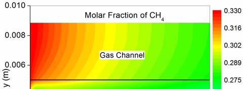
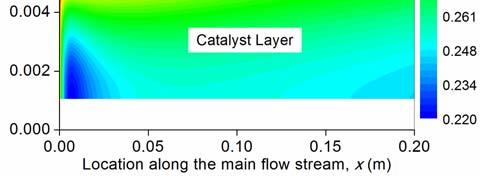
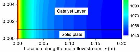
9 and reaction kinetics in CR. The effects of SCR and the catalyst nature on CR performance are not included but will be considered in future works. 3.1 Coupled transport and reaction in a compact reformer for hydrogen production Figure 3 shows the distributions of MSR reaction rates, WGSR rates, temperature, velocity, gas composition (CH 4 and H 2 as examples) in the compact reformer at an inlet temperature of 1073K, inlet gas velocity of 3m.s -1, and heat supply rate (from the solid plate) of 1kW.m -2. The reaction rates for MSR and WGSR are the highest (25.4 and 14 mol.m -3.s -1 respectively) at the inlet and decrease considerably in the downstream of the reformer (Fig. 3a and 3b). The calculated reaction rates are well consistent with the experimental data from refs [18,19]. The high reaction rates near the inlet are mainly caused by high concentration of the reactants, especially the concentration of CH 4 (for MSR) and H 2 O (for WGSR). In addition, the temperature is the highest at the inlet (Fig. 3c). The calculated reaction rates for MSR are in general higher than those for WGSR (Fig. 3a and 3b). As MSR reaction is endothermic while WGSR is exothermic, the temperature decreases from 1073K at the inlet to about 1007K at the outlet (Fig. 3c). Figure 3d shows the velocity contours profile (U/U 0 ) along the main flow stream. Similar to forced duct flow, velocity ratio (U/U 0 ) increases from zero near the wall to the highest in the core zone (Fig. 3d). The velocity in the catalyst layer is negligible due to small permeation (10-10 m 2 ) used in the simulation. The molar fraction of CH 4 is found to decrease along the CR flow channel (Fig. 3e), due to MSR reaction. A locally low molar fraction of CH 4 is also observed near the inlet in the catalyst layer (Fig. 3e). This is caused by high reaction rates of MSR and slow transport of CH 4 from the gas channel into the catalyst layer. For comparison, the molar fraction of H 2 increases along the CR gas flow stream (Fig. 3f). High molar fraction of H 2 is observed in the zones near the inlet and the outlet. The high molar fraction of H 2 near the inlet (in the catalyst layer) is mainly 9
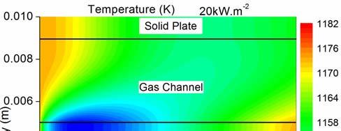
10 caused by the locally high reaction rates of MSR and WGSR. The high molar fraction of H 2 near the outlet is caused by slow diffusion and thus accumulation of H 2 in the catalyst layer Effect of inlet temperature To examine the effect of inlet temperature on CR performance, the distributions of reaction rates, temperature and gas composition at an inlet temperature of 1173K are shown in Figure 4. The reaction rates of MSR and WGSR are found to decrease along the main flow stream (Fig. 4a and 4b), but their values are significantly higher than those at 1073K (Fig. 3a and 3b). In addition, the reaction rates decrease more rapidly in the reformer than at 1073K. The high reaction rate of MSR causes the temperature to decrease rapidly along the main flow stream from 1173K at the inlet to about 1040K at the outlet (Fig. 4c). This temperature decrease is most pronounced near the inlet decrease by about 100K within 3mm downstream from the inlet due to locally high rate of MSR reaction. As the reaction rates of MSR and WGSR are higher at 1173K than at 1073K, more CH 4 is consumed and more H 2 is produced, leading to larger gas composition variation in the reformer (Fig. 4d and 4e). For example, the molar fraction of CH 4 is decreased by about 13% from the inlet to the outlet while the molar fraction of H 2 is increased by about 20% at an inlet temperature of 1173K (Fig. 4d and 4e). In a word, increasing the inlet temperature increases the reaction rates, temperature gradient, and gas composition variation Effect of heat supply rate The rate of heat supply is changed from 1kW.m -2 to 10kW.m -2 and 20kW.m -2 to investigate its effect on CR performance. As can be seen from Fig. 5, as the rate of heat supply is increased from 10kW.m -2 to 20kW.m -2, the reaction rates of both MSR and WGSR in the downstream are increased (Fig. 5a 5d). For example, the reaction rate of MSR near the surface of the catalyst 10
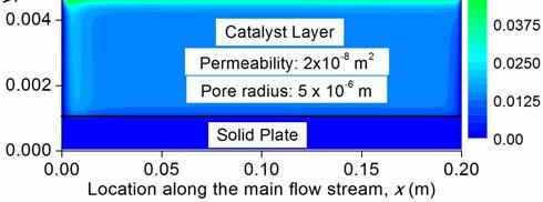
11 layer at the outlet is about 40 mol.m -3.s -1 at a heat supply rate of 20kW.m -2 (Fig. 5b), while it s only about 20 mol.m -3.s -1 when the heat supply rate is 10kW.m -2 (Fig. 5a). In addition, the reaction rates near the catalyst surface is obviously higher than inside the catalyst layer, indicating the slow transport of gas species from the gas channel into the porous catalyst layer. The higher reaction rate in the downstream is due to higher temperature at a higher rate of heat supply (Fig. 5e and 5f). As can be seen from Fig. 5e, the temperature in CR decreases rapidly along the main flow stream due to high rate of MSR, followed by slight increase in the downstream at a heat supply rate of 10kW.m -2. At a higher heat supply rate (20kW.m -2 ), the cold spot area is significantly reduced and the temperature in the downstream is even slightly higher than the inlet temperature (Fig. 5f). In addition, the lowest temperature in the reformer is increased to 1133K at a high heat supply rate (Fig. 5f) Effect of inlet gas velocity and microstructure of the catalyst layer In this section, the inlet gas velocity is increased from 3m.s -1 to 5m.s -1. The permeability and pore radius of the porous catalyst layer are increased from 2x10⁻¹⁰ m 2 to 2x10⁻⁸ m 2 and from 1μm to 5μm, respectively. The heat supply rate and inlet temperature are 10kW.m -2 and 1173K, respectively. As larger permeability and larger pore size facilitate gas permeation and diffusion into the porous catalyst layer, the reaction rates for MSR and WGSR in the downstream are propagated into the deeper catalyst layer (Fig. 6a and 6b), in comparison with Fig. 5a and 5c. Due to the slightly enhanced reaction rate in the downstream, the temperature in the reformer is slightly lower than at an inlet velocity of 3m.s -1 (Fig. 6c and 5e). The velocity contours profiles in the reformer again show similar pattern with forced duct flow (Fig. 6d). However, the core gas velocity is increased along the main flow stream to be about 1.55m.s -1. This velocity increase along the gas channel is mainly due to the fact that the total molar number of gas species increases 11
12 along the channel due to the MSR reaction (Eq. 1), which accelerates the gas flow. To examine the gas transport in the catalyst layer, the velocity contours are rescaled (Fig. 6e) and compared with the re-scaled velocity contours at an inlet velocity of 3m.s -1 (Fig. 6f). As can be seen from Fig. 6e, large permeability enhances gas transport in the porous layer and the velocity in the whole catalyst layer is non-negligible. For comparison, at a smaller permeability, the gas velocity is nonnegligible only in a very thin layer near the surface of the catalyst layer (Fig. 6f). 4. Conclusions A two-dimensional heat and mass transfer model is developed to characterize the coupled transport and reaction phenomena in a compact reformer used for hydrogen production by methane steam reforming. Different from the previous studies using re-reformed gas mixtures, the CH 4 /H 2 O mixture is directly used at the inlet of CR in the present study. It s found that the reaction rates of MSR and WGSR are the highest at the inlet but decrease considerably along the reformer, due to large temperature drop along the main flow stream. Accordingly, locally low molar fraction of CH 4 and high molar fraction of H 2 are observed near the inlet. Increasing the inlet temperature from 1073K to 1173K increases the maximum reaction rates of MSR and WGSR but shows little effect on the reaction rates in the downstream. Moreover, raising the inlet temperature to 1173K enlarges the temperature drop to about 130K. For comparison, when the rate of heat supply is increased, the temperature in the downstream of the reformer is raised, leading to enhanced reaction rates of MSR and WGSR. It s also found that increasing the gas velocity and permeability facilitates the gas transport in the porous catalyst layer, which in turn enhances the reaction rates of MSR and WGSR in the downstream. The results of the present study provide good information on how the operating and structural parameters affect the coupled transport and reaction kinetics in CR, which are important for CR stack optimization. 12
13 Acknowledgements: This research was supported by a grant (Project Number: PolyU 5238/11E) from Research Grant Council (RGC) of Hong Kong. 13
14 Symbols Used B g [m 2 ] Permeability of electrode c p [kj kg -1 K -1 ] Heat capactity D [m 2 s -1 ] Effective diffusion coefficient of species i eff i D [m 2 s -1 ] Knudsen diffusion coefficient of i ik, D i, j [m 2 s -1 ] Binary diffusion coefficient of i and j F [C mol -1 ] Faraday constant k [W m -1 K -1 ] Thermal conductivity L [m] Thickness of electrolyte M i [kg mol -1 ] Molecular weight of species i P [atm] Operating pressure R [kj mol -1 K -1 ] Universal gas constant R [mol m -3 s -1 ] Rate of methane steam reforming reaction MSR R [mol m -3 s -1 ] Rate of water gas shift reaction p WGSR r [m] Mean pore radius of electrode S m [kg m -3 s -1 ] Source term in continuity equation S x, S y [kg m -2 s -2 ] Source terms in momentum equations S T [W m -3 ] Source term in energy equation S sp [kg m -3 s -1 ] Source term in species equations S [kj mol -1 K -1 ] Entropy change T [K] Operating temperature U [m s -1 ] Velocity in x direction U 0 [m s -1 ] Gas velocity at the inlet V [m s -1 ] Velocity in y direction X i [-] Molar fraction of species i Y i [-] Mass fraction of species i [kg m -1 s -1 ] Viscosity [-] Electrode porosity [-] Electrode tortuosity D [-] Dimensionless diffusion collision integral [kg m -3 ] Density of the gas mixture 14
15 References: [1] M. Granovskii, I. Dincer, M.A. Rosen, I. Pioro, Performance assessment of a combined system to link a supercritical water-cooled nuclear reactor and a thermaochemical water splitting cycle for hydrogen production, Energy Conversion and Management 49(2008) [2] M. Ni, M.K.H. Leung, D.Y.C. Leung, K. Sumathy, A review and recent developments in photocatalytic water-splitting using TiO2 for hydrogen production, Renewable and Sustainable Energy Reviews 11(2007) [3] R. Rivera-Tinoco, C. Mansilla, C. Bouallou, Competitiveness of hydrogen production by high temperature electrolysis: impact of the heat source and identification of key parameters to achieve low production cost, Energy Conversion and Management 51(2010) [4] S.J. Yoon, Y. Choi, J. Lee, Hydrogen production from biomass tar by catalytic steam reforming, Energy Conversion and Management 51(2010) [5] J. Xuan, M.K.H. Leung, D.Y.C. Leung, M. Ni, Integrating chemical kinetics with CFD modelling for autothermal reforming of biogas, Int. J. Hydrogen Energy 34(2009) [6] J.L. Yuan, X.R. Lv, B. Sunden, D.T. Yue, Analysis of parameter effects on transport phenomena in conjunction with chemical reactions in ducts relevant for methane reformers, Int. J. Hydrogen Energy 32(2007) [7] M. Zanfir, A. Gavriilidis, Catalytic combustion assisted methane steam reforming in a catalytic plate reactor, Chem. Eng. Sci. 58(2003) [8] J.L. Yuan, F. Ren, B. Sunden, Analysis of chemical-reaction-coupled mass and heat transport phenomena in a methane reformer duct for PEMFCs, Int. J. Heat Mass Transfer 50(2007), [9] T.S. Lee, J.N. Chung, Y.C. Chen, Design and optimization of a combined fuel reforming and solid oxide fuel cell system with anode off-gas recycling, Energy Conversion and Management 52(2011) [10] T. Jiang, Q. Zhang, T.J. Wang, Q. Zhang, L.L. Ma, High yield of pentane production by aqueous-phase reforming of xylitol over Ni/HZSM-5 and Ni/MCM22 catalysts, Energy Conversion and Management 59(2012) [11] B.A. Haberman, J.B. Young, Three-dimensional simulation of chemically reacting gas flows in the porous support structure of an integrated-planar solid oxide fuel cell, Int. J. Heat Mass Transfer 47(2004) [12] M.W. Chase, NIST-JANAF thermochemical tables. (4 th edition) American Chemical Society, American Institute of Physics for the National Institute of Standards and technology (1998). [13] M. Ni, 2D thermal modeling of a solid oxide electrolyzer cell (SOEC) for syngas production by H 2 O/CO 2 co-electrolysis, Int. J. Hydrogen Energy 37(2012) [14] C.Y. Wang, Fundamental models for fuel cell engineering, Chem. Rev. 104(2004) [15] M. Ni, Thermo-electrochemical modelling of ammonia-fueled solid oxide fuel cells considering ammonia thermal decomposition in the anode, Int. J. Hydrogen Energy 36(2011) [16] R.C. Reid, J.M. Prausnitz, B.E. Poling, The properties of gases & liquids (4th edition). McGraw-Hill Book Company, New York (1987). [17] M. Ni, Modeling of SOFC running on partially pre-reformed gas mixture, Int. J. Hydrogen Energy 37(2012) [18] W. Lehnert, J. Meusinger, F. Thom, Modeling of gas transport phenomena in SOFC anodes, Journal of Power Sources 87(2000) [19] I. Drescher, W. Lehnert, J. Meusinger, Structural properties of SOFC anodes and reactivity, Electrochimica Acta 43 (1998)
16 List of Tables Table 1. Parameters used in calculating the effective diffusion coefficients [16] Table 2 Parameters used in simulation. List of Figures* Figure 1. Schematic of a compact reformer (CR) (adapted from [6]) Figure 2. Computational domain Figure 3. Coupled transport and reaction in the CR at an inlet temperature of 1073K, inlet gas velocity of 3m.s -1 ; and heat supply rate of 1kW.m -2 (a) reaction rate of MSR; (b) reaction rate of WGSR, (c) temperature; (d) velocity ratio U/U 0 ; (e) molar fraction of CH 4 ; and (f) molar fraction of H 2 Figure 4. Coupled transport and reaction in the CR at an inlet temperature of 1173K, inlet gas velocity of 3m.s -1 ; and heat supply rate of 1kW.m -2 (a) reaction rate of MSR; (b) reaction rate of WGSR, (c) temperature; (d) molar fraction of CH 4 ; and (e) molar fraction of H 2 Figure 5. Effect of heat supply rate on CR performance at an inlet temperature of 1173K and inlet gas velocity of 3m.s -1 (a) reaction rate of MSR at 10kW.m -2 ; (b) reaction rate of MSR at 20kW.m -2, (c) reaction rate of WGSR at 10kW.m -2 ; (d) reaction rate of WGSR at 20kW.m -2 ; (e) temperature at 10kW.m -2 ; and (f) temperature at 20kW.m -2 Figure 6. Coupled transport and reaction phenomena in CR at an inlet temperature of 1173K and rate of heat supply of 10kW.m -2, the permeability of the catalyst layer: 2x10⁻⁸ m 2, pore radius: 5μm (a) reaction rate of MSR; (b) reaction rate of WGSR; (c) temperature; (d) velocity; (e) velocity rescaled; (f) velocity rescaled for CR at inlet velocity of 3m.s -1, pore radius of 1 μm, permeability of 2x10⁻¹⁰ m 2. * Note: All figures are to be reproduced in color on the Web (free of charge) and in black-and-white in print 16
17 Table 1. Parameters used in calculating the effective diffusion coefficients [16] CO CO 2 H 2 O 2 CH 4 N 2 H 2 O i / k i Table 2 Parameters used in simulation. Parameter Value Operating temperature, T (K) 1173 Operating pressure, P (bar) 1.0 Porosity of the porous catalyst layer, ε 0.4 Tortuosity of the porous catalyst layer, 3.0 Permeability of the porous catalyst layer, B, (m 2 10 ) 2 10 g Average pore radius, r p (μm) 1.0 Thickness of the porous catalyst layer (cm) 0.4 Length of the Compact Reformer (cm) 20 Thickness of solid plate (cm) 0.1 Inlet velocity at the reforming duct: U 0 (m.s -1 ) 3.0 Height of the reforming duct (cm)

18 Figure 1. Figure 2 18
 (d)")


19 (a) (b) (c) (d) (e) Figure 3. (f) 19
 (d)")
 20")


20 (a) (b) (c) (d) Figure 4. (e) 20
 (d)")


21 (a) (b) (c) (d) (e) Figure 5. (f) 21
 (d)")


22 (a) (b) (c) (d) (e) Figure 6. (f) 22
Modeling and Parametric Simulations of Solid Oxide Fuel Cells with Methane Carbon Dioxide Reforming
 This is the Pre-Published Version. Modeling and Parametric Simulations of Solid Oxide Fuel Cells with Methane Carbon Dioxide Reforming Meng Ni* Building Energy Research Group, Department of Building and
Parameter Effects on Transport Phenomena in Conjunction with Internal Reforming Reactions in Intermediate Temperature SOFCs
 1909 10.1149/1.2729303, The Electrochemical Society Parameter Effects on Transport Phenomena in Conjunction with Internal Reforming Reactions in Intermediate Temperature SOFCs Jinliang Yuan a,*, Wei Guo
SOFC modeling considering hydrogen and carbon monoxide as electrochemical reactants
 SOFC modeling considering hydrogen and carbon monoxide as electrochemical reactants Andersson, Martin; Yuan, Jinliang; Sundén, Bengt Published in: Journal of Power Sources DOI: 10.1016/j.jpowsour.01.1.1
Grading the amount of electrochemcial active sites along the main flow direction of an SOFC Andersson, Martin; Yuan, Jinliang; Sundén, Bengt
 Grading the amount of electrochemcial active sites along the main flow direction of an SOFC Andersson, Martin; Yuan, Jinliang; Sundén, Bengt Published in: Journal of the Electrochemical Society DOI: 10.1149/2.026301jes
SCIENCES & TECHNOLOGY
 Pertanika J. Sci. & Technol. 22 (2): 645-655 (2014) SCIENCES & TECHNOLOGY Journal homepage: http://www.pertanika.upm.edu.my/ Numerical Modelling of Molten Carbonate Fuel Cell: Effects of Gas Flow Direction
CFD study of gas mixing efficiency and comparisons with experimental data
 17 th European Symposium on Computer Aided Process Engineering ESCAPE17 V. Plesu and P.S. Agachi (Editors) 2007 Elsevier B.V. All rights reserved. 1 CFD study of gas mixing efficiency and comparisons with
Interactions between oxygen permeation and homogeneous-phase fuel conversion on the sweep side of an ion transport membrane
 Interactions between oxygen permeation and homogeneous-phase fuel conversion on the sweep side of an ion transport membrane The MIT Faculty has made this article openly available. Please share how this
Solid Oxide Fuel Cell Material Structure Grading in the Direction Normal to the Electrode/Electrolyte Interface using COMSOL Multiphysics
 Solid Oxide Fuel Cell Material Structure Grading in the Direction Normal to the Electrode/Electrolyte Interface using COMSOL Multiphysics M. Andersson*, B. Sundén, Department of Energy Sciences, Lund University,
The effect of electrolyte type on performance of solid oxide fuel cells running on hydrocarbon fuels
 international journal of hydrogen energy 38 (2013) 2846e2858 Available online at www.sciencedirect.com journal homepage: www.elsevier.com/locate/he The effect of electrolyte type on performance of solid
The effect of heat transfer on the polarizations within an intermediate temperature solid oxide fuel cell
 Advanced Computational Methods and Experiments in Heat Transfer XII 3 The effect of heat transfer on the polarizations within an intermediate temperature solid oxide fuel cell M. Navasa, M. Andersson,
CFD Modeling: Different Kinetic Approaches for Internal Reforming Reactions in an Anode-Supported SOFC
 Hedvig Paradis 1 e-mail: hedvig.paradis@energy.lth.se Martin Andersson Jinliang Yuan Bengt Sundén Department of Energy Sciences, Faculty of Engineering, Lund University, P.O. Box 118, 221 00 Lund, Sweden
Ceramic Processing Research
 Journal of Ceramic Processing Research. Vol. 8, No. 3, pp. 224-228 (2007) J O U R N A L O F Ceramic Processing Research Computer modeling of single-chamber SOFCs with hydrocarbon fuel Jeong-Hwa Cha 1,2,
Multi-physics Simulation of a Circular-Planar Anode-Supported Solid Oxide Fuel Cell
 Multi-physics Simulation of a Circular-Planar Anode-Supported Solid Oxide Fuel Cell Keyvan Daneshvar *1, Alessandro Fantino 1, Cinzia Cristiani 1, Giovanni Dotelli 1, Renato Pelosato 1, Massimo Santarelli
Ugur Pasaogullari, Chao-Yang Wang Electrochemical Engine Center The Pennsylvania State University University Park, PA, 16802
 Computational Fluid Dynamics Modeling of Proton Exchange Membrane Fuel Cells using Fluent Ugur Pasaogullari, Chao-Yang Wang Electrochemical Engine Center The Pennsylvania State University University Park,
Analysis of parameter effects on chemical reaction coupled transport phenomena in SOFC anodes
 Heat Mass Transfer (2009) 45:471 484 DOI 10.1007/s00231-008-0449-6 ORIGINAL Analysis of parameter effects on chemical reaction coupled transport phenomena in SOFC anodes Jinliang Yuan Æ Yuan Huang Æ Bengt
On Analysis of Chemical Reactions Coupled Gas Flows in SOFCs
 On Analysis of Chemical Reactions Coupled Gas Flows in SOFCs Jinliang YUAN 1,*, Guogang YANG 2, Bengt SUNDÉN 1 * Corresponding author: Tel.: ++46 (0)46 222 4813; Fax: ++46 (0) 46 222 4717; Email: jinliang.yuan@energy.lth.se
Multidimensional, Non-Isothermal, Dynamic Modelling Of Planar Solid Oxide Fuel Cells
 Multidimensional, Non-Isothermal, Dynamic Modelling Of Planar Solid Oxide Fuel Cells K. Tseronis a, I. Kookos b, C. Theodoropoulos a* a School of Chemical Engineering and Analytical Science, University
Three-Dimensional Simulation of Mixing Flow in a Porous Medium with Heat and Mass Transfer in a Moisture Recovery System
 12 th Fluid Dynamics Conference, Babol Noshirvani University of Technology, 28-30 April 2009 Three-Dimensional Simulation of Mixing Flow in a Porous Medium with Heat and Mass Transfer in a Moisture Recovery
Prof. Mario L. Ferrari
 Sustainable Energy Mod.1: Fuel Cells & Distributed Generation Systems Dr. Ing. Mario L. Ferrari Thermochemical Power Group (TPG) - DiMSET University of Genoa, Italy Lesson II Lesson II: fuel cells (electrochemistry)
SOFC Modeling Considering Electrochemical Reactions at the Active Three Phase Boundaries
 SOFC Modeling Considering Electrochemical Reactions at the Active Three Phase Boundaries Andersson, Martin; Yuan, Jinliang; Sundén, Bengt Published in: International Journal of Heat and Mass Transfer DOI:
Modeling as a tool for understanding the MEA. Henrik Ekström Utö Summer School, June 22 nd 2010
 Modeling as a tool for understanding the MEA Henrik Ekström Utö Summer School, June 22 nd 2010 COMSOL Multiphysics and Electrochemistry Modeling The software is based on the finite element method A number
CATALYTIC STEAM REFORMING OF TOLUENE POST- GASIFICATION USING AS MODEL COMPOUND OF TAR PRODUCED BY BIOMASS GASIFICATION
 CATALYTIC STEAM REFORMING OF TOLUENE POST- GASIFICATION USING AS MODEL COMPOUND OF TAR PRODUCED BY BIOMASS GASIFICATION J. D. SILVA, C.C.B. OLIVEIRA AND C. A. M. ABREU 1 Polytechnic School UPE, Laboratory
Three-Dimensional Computational Fluid Dynamics Modeling of Solid Oxide Electrolysis Cells and Stacks
 INL/CON-08-14297 PREPRINT Three-Dimensional Computational Fluid Dynamics Modeling of Solid Oxide Electrolysis Cells and Stacks 8 th European SOFC Forum Grant Hawkes James O Brien Carl Stoots Stephen Herring
Modeling of a one dimensional Anode supported high temperature tubular SOFC
 International Journal of ChemTech Research CODEN (USA): IJCRGG, ISSN: 0974-4290, ISSN(Online):2455-9555 Vol.10 No.6, pp 784-792, 2017 Modeling of a one dimensional Anode supported high temperature tubular
Review of temperature distribution in cathode of PEMFC
 Project Report 2008 MVK 160 Heat and Mass Transport May 08, 2008, Lund, Sweden Review of temperature distribution in cathode of PEMFC Munir Ahmed Khan Department of Energy Sciences, Lund Institute of Technology,
FINITE ELEMENT METHOD MODELLING OF A HIGH TEMPERATURE PEM FUEL CELL
 CONDENSED MATTER FINITE ELEMENT METHOD MODELLING OF A HIGH TEMPERATURE PEM FUEL CELL V. IONESCU 1 1 Department of Physics and Electronics, Ovidius University, Constanta, 900527, Romania, E-mail: ionescu.vio@gmail.com
Applied Energy 87 (2010) Contents lists available at ScienceDirect. Applied Energy. journal homepage:
 Contents lists available at ScienceDirect. Applied Energy. journal homepage:") Applied Energy 87 (2010) 1461 1476 Contents lists available at ScienceDirect Applied Energy journal homepage: www.elsevier.com/locate/apenergy Review on modeling development for multiscale chemical reactions
Applied Energy 87 (2010) 1461 1476 Contents lists available at ScienceDirect Applied Energy journal homepage: www.elsevier.com/locate/apenergy Review on modeling development for multiscale chemical reactions
Performance Analysis of a Two phase Non-isothermal PEM Fuel Cell
 Performance Analysis of a Two phase Non-isothermal PEM Fuel Cell A. H. Sadoughi 1 and A. Asnaghi 2 and M. J. Kermani 3 1, 2 Ms Student of Mechanical Engineering, Sharif University of Technology Tehran,
On Continuum Models for Heat Transfer in Small Scale Porous Materials Professor Jinliang Yuan
 On Continuum Models for Heat Transfer in Small Scale Porous Materials Professor Jinliang Yuan August 30, 2013 Department of Energy Sciences Lund University, Sweden Jinliang.yuan@energy.lth.se Why porous
Computational Analysis of Heat Transfer in Air-cooled Fuel Cells
 Proceedings of ASME 2011, 5th International Conference on Energy Sustainability & 9th Fuel Cell Science, Engineering and Technology Conference, ESFuelCell2011 August 7-10, 2011, Washington, DC, USA ESFuelCell2011-54794
R11.3. Diffusion and Reaction Facilitated Heat Transfer
 Chapter 11 Professional Reference Shelf R11.3. Diffusion and Reaction Facilitated Heat Transfer When diffusion is coupled with a reversible reaction contained between two surfaces, there is an increase
Three-Dimensional CFD Modeling of Transport Phenomena in a Cross-Flow Anode-Supported Planar SOFC
 Energies 2014, 7, 80-98; doi:10.3390/en7010080 Article OPEN ACCESS energies ISSN 1996-1073 www.mdpi.com/journal/energies Three-Dimensional CFD Modeling of Transport Phenomena in a Cross-Flow Anode-Supported
Electrochemical and thermo-fluid modeling of a tubular solid oxide fuel cell with accompanying indirect internal fuel reforming
 CHAPTER 3 Electrochemical and thermo-fluid modeling of a tubular solid oxide fuel cell with accompanying indirect internal fuel reforming K. Suzuki 1, H. Iwai 2 & T. Nishino 2 1 Department of Machinery
Basic overall reaction for hydrogen powering
 Fuel Cell Basics Basic overall reaction for hydrogen powering 2H 2 + O 2 2H 2 O Hydrogen produces electrons, protons, heat and water PEMFC Anode reaction: H 2 2H + + 2e Cathode reaction: (½)O 2 + 2H +
A Current-Voltage Model for Hydrogen Production by Electrolysis of Steam Using Solid Oxide Electrolysis Cell (SOEC)
") 15 th International Conference on Environmental Science and Technology Rhodes, Greece, 31 August to 2 September 2017 A Current-Voltage Model for Hydrogen Production by Electrolysis of Steam Using Solid
15 th International Conference on Environmental Science and Technology Rhodes, Greece, 31 August to 2 September 2017 A Current-Voltage Model for Hydrogen Production by Electrolysis of Steam Using Solid
Study Of Molar Flow, Mole Fraction, Partial Pressure Variation In Process Of Pure Hydrogen Production In Multichannel Membrane Reactor
 Study Of Molar Flow, Mole Fraction, Partial Pressure Variation In Process Of Pure Hydrogen Production In Multichannel Membrane Reactor Narges Rahimi Department: Chemical Engineering South Tehran Branch,
Mathematical Investigation and CFD Simulation of Monolith Reactors: Catalytic Combustion of Methane
 Excerpt from the Proceedings of the COMSOL Conference 8 Hannover Mathematical Investigation and CFD Simulation of Monolith Reactors: Catalytic Combustion of Methane Maryam Ghadrdan *,, Hamid Mehdizadeh
Model for Steam Reforming of Ethanol Using a Catalytic Wall Reactor
 Excerpt from the Proceedings of the COMSOL Conference 28 Hannover Model for Steam Reforming of Ethanol Using a Catalytic Wall Reactor J.A. Torres *1 and D. Montané 2 1 Centre Huile Lourde Ouvert et Expérimental
Air Flow Modeling and Performance Prediction of the. Integrated-Planar Solid Oxide Fuel Cell IP-SOFC
 Applied Mathematical Sciences, Vol. 7, 2013, no. 96, 4775-4788 HIKARI Ltd, www.m-hikari.com http://dx.doi.org/10.12988/ams.2013.36296 Air Flow Modeling and Performance Prediction of the Integrated-Planar
Steady-State Molecular Diffusion
 Steady-State Molecular Diffusion This part is an application to the general differential equation of mass transfer. The objective is to solve the differential equation of mass transfer under steady state
Introduction to Solid Oxide Fuel Cells. Solid Oxide Fuel Cell (SOFC)
") Introduction to Solid Oxide Fuel Cells Basics Electrochemistry Microstructure Effects Stacks Solid Oxide Fuel Cell (SOFC) CATHODE: (La,Sr)(Mn)O 3 (LSM) LSM-YSZ ELECTROLYTE: ANODE: Y-doped ZrO 2 (YSZ) Ni-YSZ
Introduction to Solid Oxide Fuel Cells Basics Electrochemistry Microstructure Effects Stacks Solid Oxide Fuel Cell (SOFC) CATHODE: (La,Sr)(Mn)O 3 (LSM) LSM-YSZ ELECTROLYTE: ANODE: Y-doped ZrO 2 (YSZ) Ni-YSZ
AAE COMBUSTION AND THERMOCHEMISTRY
 5. COMBUSTIO AD THERMOCHEMISTRY Ch5 1 Overview Definition & mathematical determination of chemical equilibrium, Definition/determination of adiabatic flame temperature, Prediction of composition and temperature
sensors ISSN by MDPI
 Sensors 008, 8, 1475-1487 Full Research Paper sensors ISSN 144-80 008 by MDPI www.mdpi.org/sensors Three-Dimensional Transport Modeling for Proton Exchange Membrane(PEM) Fuel Cell with Micro Parallel Flow
5. Diffusion/Reaction Application
 5. Diffusion/Reaction Application Diffusion of the reactants from the surface of the catalyst to the interior of its pores constitutes one of the resistances in a reaction system catalyzed by the solid
2018 GPSC VCE Chemistry Unit 3 Outline Efficient Production and Use of Energy and Materials
 2018 GPSC VCE Chemistry Unit 3 Outline Efficient Production and Use of Energy and Materials The theme of Unit 3 is the efficient production and use of energy and materials. This booklet provides an outline
INTRODUCTION TO CATALYTIC COMBUSTION
 INTRODUCTION TO CATALYTIC COMBUSTION R.E. Hayes Professor of Chemical Engineering Department of Chemical and Materials Engineering University of Alberta, Canada and S.T. Kolaczkowski Professor of Chemical
CHE 611 Advanced Chemical Reaction Engineering
 CHE 611 Advanced Chemical Reaction Engineering Dr. Muhammad Rashid Usman Institute of Chemical Engineering and Technology University of the Punjab, Lahore 54590 mrusman.icet@pu.edu.pk 1 Diffusion and reaction
Diffusion and Adsorption in porous media. Ali Ahmadpour Chemical Eng. Dept. Ferdowsi University of Mashhad
 Diffusion and Adsorption in porous media Ali Ahmadpour Chemical Eng. Dept. Ferdowsi University of Mashhad Contents Introduction Devices used to Measure Diffusion in Porous Solids Modes of transport in
CFD-DEM SIMULATION OF SYNGAS-TO-METHANE PROCESS IN A FLUIDIZED-BED REACTOR
 Refereed Proceedings The 13th International Conference on Fluidization - New Paradigm in Fluidization Engineering Engineering Conferences International Year 010 CFD-DEM SIMULATION OF SYNGAS-TO-METHANE
Phone: , For Educational Use. SOFTbank E-Book Center, Tehran. Fundamentals of Heat Transfer. René Reyes Mazzoco
 8 Fundamentals of Heat Transfer René Reyes Mazzoco Universidad de las Américas Puebla, Cholula, Mexico 1 HEAT TRANSFER MECHANISMS 1.1 Conduction Conduction heat transfer is explained through the molecular
Computational model of a PEM fuel cell with serpentine gas flow channels
 Journal of Power Sources 130 (2004) 149 157 Computational model of a PEM fuel cell with serpentine gas flow channels Phong Thanh Nguyen, Torsten Berning 1, Ned Djilali Institute for Integrated Energy Systems,
ENGINEERING OF NUCLEAR REACTORS
 22.312 ENGINEERING OF NUCLEAR REACTORS Monday, December 17 th, 2007, 9:00am-12:00 pm FINAL EXAM SOLUTIONS Problem 1 (45%) Analysis of Decay Heat Removal during a Severe Accident i) The energy balance for
This section develops numerically and analytically the geometric optimisation of
 7 CHAPTER 7: MATHEMATICAL OPTIMISATION OF LAMINAR-FORCED CONVECTION HEAT TRANSFER THROUGH A VASCULARISED SOLID WITH COOLING CHANNELS 5 7.1. INTRODUCTION This section develops numerically and analytically
Theoretical and Experimental Studies on Transient Heat Transfer for Forced Convection Flow of Helium Gas over a Horizontal Cylinder
 326 Theoretical and Experimental Studies on Transient Heat Transfer for Forced Convection Flow of Helium Gas over a Horizontal Cylinder Qiusheng LIU, Katsuya FUKUDA and Zheng ZHANG Forced convection transient
Flame / wall interaction and maximum wall heat fluxes in diffusion burners
 Flame / wall interaction and maximum wall heat fluxes in diffusion burners de Lataillade A. 1, Dabireau F. 1, Cuenot B. 1 and Poinsot T. 1 2 June 5, 2002 1 CERFACS 42 Avenue Coriolis 31057 TOULOUSE CEDEX
A Shrinking Core Model for Steam Hydration of CaO-Based Sorbents Cycled for CO2 Capture: Supplementary Information
 A Shrinking Core Model for Steam Hydration of CaO-Based Sorbents Cycled for CO2 Capture: Supplementary Information John Blamey 1, Ming Zhao 2, Vasilije Manovic 3, Edward J. Anthony 3, Denis R. Dugwell
Using LBM to Investigate the Effects of Solid-Porous Block in Channel
 International Journal of Modern Physics and Applications Vol. 1, No. 3, 015, pp. 45-51 http://www.aiscience.org/journal/ijmpa Using LBM to Investigate the Effects of Solid-Porous Bloc in Channel Neda Janzadeh,
Computational Fluid Dynamics Analysis on Transport Phenomena in Solid Oxide Electrochemical Cells
 Computational Fluid Dynamics Analysis on Transport Phenomena in Solid Oxide Electrochemical Cells Maria Navasa Thesis for the degree of Licentiate of Engineering, 2013 Division of Heat Transfer Department
Modeling of the Unsteady State Methanol Synthesis at the Level of Catalyst Pellet
 Modeling of the Unsteady State Methanol Synthesis at the Level of Catalyst Pellet IONUT BANU, IOANA STOICA, GHEORGHE BUMBAC, GRIGORE BOZGA* University Politehnica of Bucharest, Department of Chemical and
DARS Digital Analysis of Reactive Systems
 DARS Digital Analysis of Reactive Systems Introduction DARS is a complex chemical reaction analysis system, developed by DigAnaRS. Our latest version, DARS V2.0, was released in September 2008 and new
Co-Generation of C2 Hydrocarbons and Synthesis Gases from Methane and Carbon Dioxide: a Thermodynamic Analysis
 Diponegoro University From the SelectedWorks of Istadi August, 2005 Co-Generation of C2 Hydrocarbons and Synthesis Gases from Methane and Carbon Dioxide: a Thermodynamic Analysis Istadi Istadi, Diponegoro
e - Galvanic Cell 1. Voltage Sources 1.1 Polymer Electrolyte Membrane (PEM) Fuel Cell
 Fuel Cell") Galvanic cells convert different forms of energy (chemical fuel, sunlight, mechanical pressure, etc.) into electrical energy and heat. In this lecture, we are interested in some examples of galvanic cells.
Galvanic cells convert different forms of energy (chemical fuel, sunlight, mechanical pressure, etc.) into electrical energy and heat. In this lecture, we are interested in some examples of galvanic cells.
LECTURE 4 Variation of enthalpy with temperature
 LECTURE 4 Variation of enthalpy with temperature So far, we can only work at 25 C. Like c v we define a constant pressure heat capacity, c p, as the amount of heat energy needed to raise the temperature
Studies on flow through and around a porous permeable sphere: II. Heat Transfer
 Studies on flow through and around a porous permeable sphere: II. Heat Transfer A. K. Jain and S. Basu 1 Department of Chemical Engineering Indian Institute of Technology Delhi New Delhi 110016, India
A 3-dimensional planar SOFC stack model
 A 3-dimensional planar SOFC stack model Michel Bernier, James Ferguson and Raphaèle Herbin 1 Introduction A fuel cell converts chemical energy to electrical energy through electro-chemical reactions at
Hydrogen production by electrolysis. Ann Cornell, Department of Chemical Engineering, KTH
 Hydrogen production by electrolysis Ann Cornell, Department of Chemical Engineering, KTH amco@kth.se Sources for hydrogen International Energy Agency. Technology Roadmap Hydrogen and Fuel Cells, 2015
Modeling of Packed Bed Reactors: Hydrogen Production by the Steam Reforming of Methane and Glycerol
 Modeling of Packed Bed Reactors: Hydrogen Production by the Steam Reforming of Methane and Glycerol A. G. Dixon *,1, B. MacDonald 1, A. Olm 1 1 Department of Chemical Engineering, Worcester Polytechnic
Gestão de Sistemas Energéticos 2017/2018
 Gestão de Sistemas Energéticos 2017/2018 Exergy Analysis Prof. Tânia Sousa taniasousa@tecnico.ulisboa.pt Conceptualizing Chemical Exergy C a H b O c enters the control volume at T 0, p 0. O 2 and CO 2,
FEDSM-ICNMM
 Proceedings of the ASME 2010 Fluids Engineering Summer Meeting FEDSM2010 August 1-5, 2010, Montreal, Quebec, Canada FEDSM-ICNMM2010-31192 NUMERICAL MODELING OF MINI/MICROCHANNEL REACTOR FOR METHANE-STEAM
Combustion Theory and Applications in CFD
 Combustion Theory and Applications in CFD Princeton Combustion Summer School 2018 Prof. Dr.-Ing. Heinz Pitsch Copyright 201 8 by Heinz Pitsch. This material is not to be sold, reproduced or distributed
Chemical Reactions and Kinetics of the Carbon Monoxide Coupling in the Presence of Hydrogen
 Journal of Natural Gas Chemistry 11(2002)145 150 Chemical Reactions and Kinetics of the Carbon Monoxide Coupling in the Presence of Hydrogen Fandong Meng 1,2, Genhui Xu 1, Zhenhua Li 1, Pa Du 1 1. State
Investigation of CNT Growth Regimes in a Tubular CVD Reactor Considering Growth Temperature
 ICHMT2014-XXXX Investigation of CNT Growth Regimes in a Tubular CVD Reactor Considering Growth Temperature B. Zahed 1, T. Fanaei Sheikholeslami 2,*, A. Behzadmehr 3, H. Atashi 4 1 PhD Student, Mechanical
Chemical changes. All exothermic reactions release heat energy to the surroundings. Heat given out. Products. Progress of reaction
 Chemical changes 6.1 Energetics of a reaction All chemical reactions involve an energy change. Energy is taken in or given out in the form of heat. So the reactions are divided into 2 groups Exothermic
Advanced Analytical Chemistry Lecture 12. Chem 4631
 Advanced Analytical Chemistry Lecture 12 Chem 4631 What is a fuel cell? An electro-chemical energy conversion device A factory that takes fuel as input and produces electricity as output. O 2 (g) H 2 (g)
Kc is calculated for homogeneous reactions using the concentrations of the reactants and products at equilibrium:
 Chemical Equilibrium Dynamic Equilibrium A dynamic equilibrium exists in a closed system when the rate of the forward reaction is equal to the rate of the reverse reaction. When a dynamic equilibrium is
ANALYTICAL INVESTIGATION AND IMPROVEMENT OF PERFORMANCE OF A PROTON EXCHANGE MEMBRANE (PEM) FUEL CELL IN MOBILE APPLICATIONS
 FUEL CELL IN MOBILE APPLICATIONS") Int. J. of Applied Mechanics and Engineering, 015, vol.0, No., pp.319-38 DOI: 10.1515/ijame-015-001 ANALYTICAL INVESTIGATION AND IMPROVEMENT OF PERFORMANCE OF A PROTON EXCHANGE MEMBRANE (PEM) FUEL CELL
Int. J. of Applied Mechanics and Engineering, 015, vol.0, No., pp.319-38 DOI: 10.1515/ijame-015-001 ANALYTICAL INVESTIGATION AND IMPROVEMENT OF PERFORMANCE OF A PROTON EXCHANGE MEMBRANE (PEM) FUEL CELL
D DAVID PUBLISHING. 1. Introduction. Akira Nishimura 1, Masashi Baba 1, Kotaro Osada 1, Takenori Fukuoka 1, Masafumi Hirota 1 and Eric Hu 2
 Journal of Energy and Power Engineering () - doi:./-/.. D DAVID PUBLISHING Temperature Distributions in Single Cell of Polymer Electrolyte Fuel Cell Simulated by an D Multi-plate Heat-Transfer Model and
Mathematical Investigation and CFD Simulation of Monolith Reactors: Catalytic Combustion of Methane
 Presented at the COMSOL Conference 2008 Hannover Mathematical Investigation and CFD Simulation of Monolith Reactors: Catalytic Combustion of Methane Maryam Ghadrdan Norwegian University of Science and
MODELING AND SIMULATION OF AN AUTOTHERMAL REFORMER
 Latin American Applied Research 36:89-9 (6) MODELING AND SIMULATION OF AN AUTOTHERMAL REFORMER J. PIÑA and D. O. BORIO PLAPIQUI (UNS-CONICET), Camino La Carrindanga Km 7. (8) Bahía Blanca, Argentina. julianap@plapiqui.edu.ar
Minimization of Exergy Destruction Costs for the Production of Hydrogen from Methane Cracking
 Minimization of Exergy Destruction Costs for the Production of Hydrogen from Methane Cracking Federico Gutiérrez, Federico Méndez. Abstract In the present work, the conservation principles (energy and
Methane Oxidation Reactions
 Methane Oxidation Reactions CH 4 + 2 O -> CO 2 2 + 2 H 2 O Total Oxidation (Combustion) CH 4 + 0.5 O -> CO 2 + 2 H 2 CO + 0.5 O -> CO 2 2 H 2 + 0.5 O -> H 2 2 O CH 4 + H 2 O->CO + 3 H 2 Partial Oxidation
MIXED CONVECTION HEAT TRANSFER FROM A PARTICLE IN SUPERCRITICAL WATER
 THERMAL SCIENCE, Year 2016, Vol. 20, No. 2, pp. 483-492 483 MIXED CONVECTION HEAT TRANSFER FROM A PARTICLE IN SUPERCRITICAL WATER by Liping WEI, Youjun LU*, and Jinjia WEI State Key Laboratory of Multiphase
Introduction to Mass Transfer
 Introduction to Mass Transfer Introduction Three fundamental transfer processes: i) Momentum transfer ii) iii) Heat transfer Mass transfer Mass transfer may occur in a gas mixture, a liquid solution or
Q1. (a) State what is meant by the term activation energy of a reaction. (1)
 State what is meant by the term activation energy of a reaction. (1)") Q1. (a) State what is meant by the term activation energy of a reaction. (c) State in general terms how a catalyst increases the rate of a chemical reaction. The curve below shows the Maxwell Boltzmann
Q1. (a) State what is meant by the term activation energy of a reaction. (c) State in general terms how a catalyst increases the rate of a chemical reaction. The curve below shows the Maxwell Boltzmann
NUMERICAL ANALYSIS ON 36cm 2 PEM FUEL CELL FOR PERFORMANCE ENHANCEMENT
 NUMERICAL ANALYSIS ON 36cm 2 PEM FUEL CELL FOR PERFORMANCE ENHANCEMENT Lakshminarayanan V 1, Karthikeyan P 2, D. S. Kiran Kumar 1 and SMK Dhilip Kumar 1 1 Department of Mechanical Engineering, KGiSL Institute
On heat and mass transfer phenomena in PEMFC and SOFC and modeling approaches
 On heat and mass transfer phenomena in PEMFC and SOFC and modeling approaches J. Yuan 1, M. Faghri 2 & B. Sundén 1 1 Division of Heat Transfer, Lund Institute of Technology, Sweden. 2 Department of Mechanical
Chemical reactions. C2- Topic 5
 Chemical reactions C2- Topic 5 What is a chemical reaction? A chemical reaction is a change that takes place when one or more substances (called reactants) form one or more new substances (called products)
5 Energy from chemicals
 5 Energy from chemicals Content 5.1 Enthalpy 5.2 Hydrogen fuel cell Learning Outcomes Candidates should be able to: (a) (b) (c) (d) (e) describe the meaning of enthalpy change in terms of exothermic (H
Thermodynamic and Stochiometric Principles in Materials Balance
 Thermodynamic and Stochiometric Principles in Materials Balance Typical metallurgical engineering problems based on materials and energy balance NiO is reduced in an open atmosphere furnace by excess carbon
Quantitative Relationships in Chemical Reactions Chapter 7
 Quantitative Relationships in Chemical Reactions Chapter 7 The burning of charcoal releases heat (thermal energy) that grills our food. But the combustion of charcoal and fossil fuels also releases CO
Fundamentals of Combustion
 Fundamentals of Combustion Lec 3: Chemical Thermodynamics Dr. Zayed Al-Hamamre Content Process Heat Transfer 1-3 Process Heat Transfer 1-4 Process Heat Transfer 1-5 Theoretical and Excess Air Combustion
Lifetime and Performance Prediction of SOFC Anodes Operated with Trace Amounts of Hydrogen Sulfide
 www.dlr.de Chart 1 > SOFC Forum > W. G. Bessler Presentation > 28.06.2012 Lifetime and Performance Prediction of SOFC Anodes Operated with Trace Amounts of Hydrogen Sulfide Matthias Riegraf, Günter Schiller,
PREDICTION OF PHYSICAL PROPERTIES OF FOODS FOR UNIT OPERATIONS
 PERIODICA POLYTECHNICA SER. CHEM. ENG. VOL. 45, NO. 1, PP. 35 40 (2001) PREDICTION OF PHYSICAL PROPERTIES OF FOODS FOR UNIT OPERATIONS Ágnes BÁLINT Department of Chemical Technology Budapest University
Modeling the next battery generation: Lithium-sulfur and lithium-air cells
 Modeling the next battery generation: Lithium-sulfur and lithium-air cells D. N. Fronczek, T. Danner, B. Horstmann, Wolfgang G. Bessler German Aerospace Center (DLR) University Stuttgart (ITW) Helmholtz
Optimizing the Performance of a Single PEM Fuel Cell
 Zhuqian Zhang School of Mechanical Electronic and Control Engineering, Beijing Jiaotong University, Beijing, P.R.C. Xia Wang 1 Department of Mechanical Engineering, Oakland University, Rochester, MI e-mail:
Modeling of a Coal Syngas Based SOFC
 Status, Needs and Future Applications. Morgantown WV, October 11-1, 007 Modeling of a Coal Syngas Based SOFC S. R. Pakalapati, F. Elizalde-Blancas, I. B. Celik Mechanical and Aerospace Engineering Department,
A Planar Anode - Supported Solid Oxide Fuel Cell Model with Internal Reforming of Natural Gas
 A Planar Anode - Supported Solid Oxide Fuel Cell Model with Internal Reforming of Natural Gas Penyarat Chinda, Somchai Chanchaona, Pascal Brault, Wishsanuruk Wechsatol To cite this version: Penyarat Chinda,
Modeling of Liquid Water Distribution at Cathode Gas Flow Channels in Proton Exchange Membrane Fuel Cell - PEMFC
 Modeling of Liquid Water Distribution at Cathode Gas Flow Channels in Proton Exchange Membrane Fuel Cell - PEMFC Sandro Skoda 1*, Eric Robalinho 2, André L. R. Paulino 1, Edgar F. Cunha 1, Marcelo Linardi
AQA Chemistry Checklist
 Topic 1. Atomic structure Video: Atoms, elements, compounds, mixtures Use the names and symbols of the first 20 elements in the periodic table, the elements in Groups 1 and 7, and other elements in this
Edexcel Chemistry Checklist
 Topic 1. Key concepts in chemistry Video: Developing the atomic model Describe how and why the atomic model has changed over time. Describe the difference between the plum-pudding model of the atom and