Compendium Screw Jacks
|
|
|
- Marilynn Malone
- 5 years ago
- Views:
Transcription


1 Compendium Screw Jacks
2 Screw Jack Technology Overview of chapters Useful information Project planning Screw jacks Bevel gear boxes Lifting screw protective covers Couplings and connecting shafts Accessories Overview further linear motion products General informations
3 Contents Screw jacks Construction support Specifications/Solution system Construction Configuration type 1 - Configuration type 2 1. Structural configurations SHE range type MERKUR range type SHE range type MERKUR range type HSE range type HSE range type SHG range type SHG range type
4 .1 Construction support to your specifications. Just contact your technical specialist and draw up a draft solution for your particular task at hand..1.1 Specifications/Solution system In order to help you finding the correct specification we are indicating below both the task specification and the corresponding solution. Your task specification Our solution.1.2 Construction Your task specification Symbol Our solution 2 nd guide ring Articulated head Movable travelling nut mounting Use trunnion or spherical nut support Note: Lateral forces should be avoided, as they drastically reduce the service life of the supporting nut without on site guidance Anti-turn device configuration with feather key (for low lifting forces) Mechanical lift limitation, configuration type 1 Swivel-lug configuration head IV on both screw ends or articulated joints. 28
5 Your task specification Symbol Our solution safety nut breaking accident prevention standards (persons BGV C1 (VBG 70) standards for stages and broadcasting studios installation space unit is shutdown Configuration with adjustable play housing cover. Note: Only applies to load reversal (ten sile and compression load). No readjustment is required if ball screws are used. Short safety nut Note: Monitoring is only possible in one load direction. Long safety nut Telescopic configuration Reinforced screw Single-start trapezoidal screw Tr Buttress-thread screw S [ [ P=? Multi-start trapezoidal screw Tr No self-locking system > motor brake always required Single-start trapezoidal screw with special lead Ball screw Ku or Pl planetary roller screw Efficiency rating h Ku ' h Pl ' No self-locking system > motor brake always required 29
6 .1 Construction support Your task specification Symbol Our solution Shaft encoder installation Hollow shaft flange screw jack Motor mounting flanges Swivel mounting bases Swivel plates Screw protection Spiral spring cover desired I II III IV GK Option Spindle heads Hand wheel 0
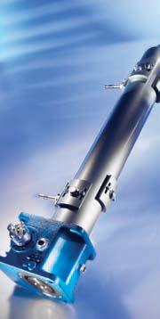
7 .2 Configuration type 1 - Configuration type 2 Type 1: Type 1: bevel gear te). Type 2: side the housing Type 2: out side the housing device fitted on site. = wheel of rotation (see type 1). Note: 1
.")

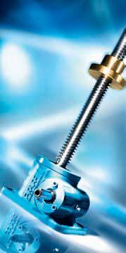
8 . Structural configurations..1 SHE range type 1 Type 1 (lifting screw)..2 MERKUR range type 1 Type 1 (lifting screw) Modular design: Modular design: for screw jacks in cubical design 2
9 . Structural configurations No. Symbol SHE range MERKUR range type 1 type 1 No. Symbol SHE range MERKUR range type 1 type P=? of standard configuration
.")

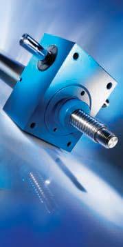
10 . Structural configurations.. SHE range type 2 Type 2 (rotating screw)..4 MERKUR range type 2 Type 2 (rotating screw) Modular design: Modular design: for screw jacks in cubical design 4
11 . Structural configurations No. Symbol SHE range MERKUR range type 2 type 2 No. Symbol SHE range MERKUR range type 2 type P=? of standard configuration 5
 and type 2 (rotating")

12 . Structural configurations..5 HSE range type 1..6 HSE range type 2 Type 1 (lifting screw) and type 2 (rotating screw) high lifting speeds Modular design for configuration type 1 and type 2: 6
13 No. Symbol HSE range HSE range type 1 type 2 No. Symbol HSE range HSE range type 1 type P=?
 and type 2")

14 . Structural configurations..7 SHG range type 1..8 SHG range type 2 Type 1 (lifting screw) and type 2 (rotating screw) long service life Modular design for configuration type 1 and type 2: 8
15 . Structural configurations No. Symbol SHG range SHG range type 1 type 2 No. Symbol SHG range SHG range type 1 type
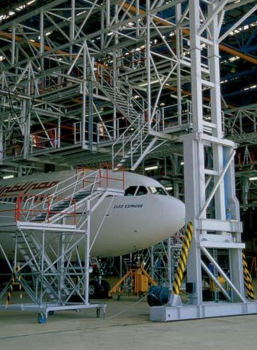
16 Application example 40
17 Contents.4 Technical information Table of settings SHE Worm gear screw jacks MERKUR Worm gear screw jacks HSE High performance worm gear screw jacks SHG Quick-lifting screw jacks Permitted buckling force Performance tables (screw jacks with Tr screw) SHE range MERKUR range HSE range SHG range Performance tables (screw jacks with Ku ball screw) HSE Ku range SHG Ku range Screw jack efficiency ratings h SHE range MERKUR range HSE range Screw efficiency ratings h Sp Critical screw turning speed Ball screw (Ku) Permitted lateral force on screw Permitted radial force on drive system 66 41
18 .4 Technical information.4.1 Table of settings Worm gear screw jacks SHE Size 0, (10) 15.1 Max. lifting capacity dyn/stat [kn] 5/5 15/15 20/20 0/45 50/75 100/150 Max. tensile load dyn/stat [kn] 5/5 10/10 19/19 0/45 50/75 99/99 Screw Tr 1) 18x6 24x5 26x6,28 0x6 40x7 60x12 Ratio N 10:1 5:1 6:1 6:1 6:1 7 2/:1 Lift per revolution for ratio N [mm/per rev.] 0,60 1,0 1,047 1,0 1,167 1,565 Ratio L 20:1 20:1 24:1 24:1 24:1 24:1 Lift per revolution for ratio L [mm/per rev.] 0,0 0,25 0,262 0,25 0,292 on request 0,50 Max. drive capacity 2) at T = 20 C Duty type S 20% - 60 min Max. drive capacity 2) at T = 20 C Duty type S 10% - 60 min [kw] 0,17 0,4 0,5 0,65 1,15 2,7 [kw] 0,25 0,6 0,75 1,25 1,9,85 Overall efficiency for ratio N [%] Overall efficiency for ratio L [%] Screw efficiency rating [%] ,5 9,5 Torque, capacity, turning-speed at 20 % ED/h and 20 C see performance tables.4..1 Screw torque at max. lifting power [Nm] 8,8 29, Max. permitted drive-shaft torque [Nm] 12 29,4 6 46,5 92 on request 195 Max. permitted screw length for compression load [mm] see buckling diagrams.4.2 Housing material G-AlSiCu4 GGG Weight without stroke length and protection tube [kg] 1,2,0 7, 7, 16,2 26,5 Screw weight per 100 mm stroke [kg] 0,14 0,26 0,2 0,45 0,82 1,79 Amount of lubricant in worm gear [kg] 0,05 0,1 0,15 0,2 0,5 0,9 Mass moment of inertia J ) Ratio N type 1 Mass moment of inertia J ) Ratio N type 2 Mass moment of inertia J ) Ratio L type 1 Mass moment of inertia J ) Ratio L type 2 [kg cm 2 ] 0,095 0,8 0,651 0,780 2,24 on request 5,256 [kg cm 2 ] 0,100 0,90 0,657 0,792 2,27 5,56 [kg cm 2 ] 0,089 0,269 0,459 0,558 1,696 4,081 [kg cm 2 ] 0,089 0,275 0,460 0,558 1,699 4,091 Dimension plans type 1 - chapter.5.1/type 2 - chapter.5.2 1) Also applies to Ku screw, see chapter.4.7 2) Max. permitted values for type 1 and Tr screw. Higher values are possible when using type 2 or Ku screw. ) Referring to 100 mm screw length 42
19 .4 Technical information Size 200/ /250 50/50 500/ / / / /2000 Max. lifting capacity dyn/stat 178/ /250 50/50 500/ / / / Max. tensile load dyn/stat 70x12 90x16 100x16 120x16 140x20 160x20 190x24 220x28 Screw Tr 1) 8:1 10 2/:1 10 2/:1 10 2/:1 12:1 12:1 19:1 17,5:1 Ratio N 1,50 1,50 1,50 1,50 1,667 1,667 1,26 1,60 Lift per revolution for ratio N 24:1 2:1 2:1 2:1 6:1 6:1 - - Ratio L 0,50 0,50 0,50 0,50 0,556 0, Lift per revolution for ratio L,8 5,0 6,0 7,4 9,0 12,5 18,5 on request Max. drive capacity 2) at T = 20 C Duty type S 20% - 60 min 5,4 7,2 8,6 10,4 12,6 17,5 26 on request Max. drive capacity 2) at T = 20 C Duty type S 10% - 60 min ,5 Overall efficiency of ratio N Overall efficiency of ratio L 7,5 6, ,6 28,5 28,8 29 Screw efficiency rating see performance tables.4..1 Torque, capacity, turning-speed at 20 % ED/h and 20 C Screw torque at max. lifting power on request Max. permitted drive-shaft torque see buckling diagrams.4.2 Max. permitted screw length for compression load GGG GS Housing material 6 70, ca ca Weight without stroke length and protection tube 2,52 4,15 5,2 7,7 10,0 1,82 19,6 26,2 Screw weight per 100 mm stroke 2,0 1, 2,5 4,0 5,0 10,0 10,0 on request Amount of lubricant in worm gear 11,9 2,42 55,80 108,8 18,0 428,5 on request on request Mass moment of inertia J ) Ratio N type 1 Mass moment of inertia J ) 12,14 2,74 56,0 109,9 25,2 41, on request on request Ratio N type 2 Mass moment of inertia J ) 9,427 19,59 44,08 88,7 275,6 46,0 on request on request Ratio L type 1 Mass moment of inertia J ) 9,451 19,62 44,1 88,49 279,4 46, on request on request Ratio L type 2 4
20 .4 Technical information Worm gear screw jacks MERKUR Size M0 M1 M2 M M4 M5 M6 M7 M8 Max. lifting capacity [kn] 2, Max. tensile load [kn] 2, Screw Tr 1) 14x4 18x4 20x4 0x6 40x7 60x9 80x10 100x10 120x14 Ratio N 4:1 4:1 4:1 6:1 7:1 9:1 10:1 10:1 14:1 Lift per revolution for ratio N [mm/per rev.] 1,0 1,0 1,0 1,0 1,0 1,0 1,0 1,0 1,0 Ratio L 16:1 16:1 16:1 24:1 28:1 6:1 40:1 40:1 56:1 Lift per revolution for ratio L [mm/per rev.] 0,25 0,25 0,25 0,25 0,25 0,25 0,25 0,25 0,25 Max. drive capacity 2) at T = 20 C Duty type S 20% - 60 min [kw] 0,12 0,2 0, 0,5 0,9 2,6,7 on request on request Max. drive capacity 2) at T = 20 Duty type S 10% - 60 min [kw] 0,25 0,42 0,6 1,1 1,9,7 4,4 on request on request Overall efficiency of ratio N [%] Overall efficiency of ratio L [%] Screw efficiency rating [%] 49 42, ,5 2, Torque, capacity, turning-speed at 20 % ED/h and 20 C see performance tables.4..2 Screw torque at max. lifting power [Nm],2 7, Max. permitted drive-shaft torque [Nm] 1,5,4 7, Max. permitted screw length for compression load [mm] see buckling diagrams.4.2 Housing material Al-Leg GG GGG Weight without stroke length and protection tube [kg] 0,6 1,2 2, Screw weight per 100 mm stroke [kg] 0,1 0,5 0,45 0,7 1,2 2 4,2 6,6 10, Amount of lubricant in worm gear [kg] 0,0 0,08 0,14 0,24 0,8 1,1 2,0 2,7,2 Mass moment of inertia J ) Ratio N type 1 Mass moment of inertia J ) Ratio N type 2 Mass moment of inertia J ) Ratio L type 1 Mass moment of inertia J ) Ratio L type 2 [kg cm 2 ] 0,070 0,122 0,160 0,780 1,917,412 16,04 49,12 96,27 [kg cm 2 ] 0,069 0,126 0,165 0,794 1,952,741 17,58 52,45 10,9 [kg cm 2 ] 0,045 0,088 0,115 0,558 1,71 2,628 12,5 7,05 72,62 [kg cm 2 ] 0,050 0,091 0,119 0,552 1,81 2,647 12,44 7,7 7,15 Dimension plans type 1 - chapter.6.1/type 2 - chapter.6.2 1) 2) ) Also applies to Ku screw, see chapter.4.7 Max. permitted values for type 1 and Tr screw. Higher values are possible when using type 2 or Ku screw. Referring to 100 mm screw length 44
21 .4 Technical information.4.1. High performance worm gear screw jacks HSE Size 2 4) Max. lifting capacity [kn] Max. tensile load [kn] Screw Tr 1) 18x6 24x5 40x8 50x9 60x12 70x12 100x16 160x20 Ratio N 4:1 5:1 6:1 7:1 8:1 8:1 10 2/:1 1 1/:1 Lift per revolution for ratio N [mm/per rev.] 1,5 1,0 1, 1,28 1,5 1,5 1,5 1,5 Ratio L 16:1 20:1 24:1 28:1 2:1 2:1 2:1 on request 40:1 Lift per revolution for ratio L [mm/per rev.] 0,75 0,25 0, 0,2 0,75 0,75 0,5 0,5 Max. drive capacity 2) at T = 20 C Duty type S 20% - 60 min [kw] 0,60 0,90 1,5 2,,6 4,8 7,7 17,9 Max. drive capacity 2 ) at T = 20 C Duty type S 10% - 60 min [kw] 1,0 1,5 2,6 4,0 6, 8,4 1,5 1 Overall efficiency of ratio N [%] Overall efficiency of ratio L [%] see efficiency ratings tables.4.5. Screw efficiency rating [%] ,5 9,5 5,5 4 on request 28,5 Torque, capacity, turning-speed at 20 % ED/h and 20 C see performance tables.4.. Screw torque at max. lifting power [Nm] 7,4 18, Max. permitted drive-shaft torque [Nm] 12,6 29,4 48, on request 4260 Max. permitted screw length for compression load [mm] see buckling diagrams.4.2 Housing material AlSi 12 GGG 50 Weight without stroke length and protection tube [kg] 2,0 4, Screw weight per 100 mm stroke [kg] 0,16 0,2 0,82 1, 1,79 2,52 5,2 1,82 Amount of lubricant in worm gear [kg] 0,07 0,15 0,4 0,9 1,5 2,1 5,0 15,5 Mass moment of inertia J ) Ratio N type 1 Mass moment of inertia J ) Ratio N type 2 Mass moment of inertia J ) Ratio L type 1 Mass moment of inertia J ) Ratio L type 2 [kg cm 2 ] 0,27 0,466 1,247,100 11,97 0,11 60,76 on request - [kg cm 2 ] 0,270 0,51 1,64,78 1,05 2,21 65,76 - [kg cm 2 ] 0,150 0,204 0,68 1,804 8,1 20,91 44,88 - [kg cm 2 ] 0,15 0,207 0,645 1,822 8,20 21,04 45,4 - Dimension plans type 1 - chapter.7.1/type 2 - chapter.7.2 1) 2) ) 4) Also applies to Ku screw, see chapter.4.7 Max. permitted values for type 1 and Tr screw. Higher values are possible when using type 2 or Ku screws. Referring to 100 mm screw length Size 2 replaces previous size 1. 45
22 .4 Technical information Quick-lifting screw jacks SHG Size G 15 G 25 G 50 G 90 Max. lifting capacity [kn] Max. tensile load [kn] Screw Tr 1) 24x5 5x8 40x7 60x9 Ratio N 2:1 Lift per revolution for ratio N [mm/per rev.] 2,5 4,5 4,5 Ratio L :1 Lift per revolution for ratio L [mm/per rev.] 1,66 2,67 2, Max. drive capacity 2) at T = 20 C Duty type S 20% - 60 min [kw] 1,0 1,5 2,4 8,9 Max. drive capacity 2) at T = 20 C Duty type S 10% - 60 min [kw] 1, 2,6,8 1 Screw efficiency rating [%] Torque, capacity, turning-speed at 20 % ED/h and 20 C see performance tables.4..4 Screw torque at max. lifting power [Nm] 29,4 7,2 12,4 98,5 Max. permitted drive-shaft torque [Nm] Max. permitted screw length for compression load [mm] see buckling diagrams.4.2 Housing material GG AlSi10Mg GG Weight without stroke length and protection tube [kg] 9 1, Screw weight per 100 mm stroke [kg] 0,8 0,59 1,5 2,5 Amount of lubricant in worm gear [kg] 0,15 0,9 0,6,5 Mass moment of inertia J ) Ratio N type 1 [kg cm 2 ] 1,058 6,6 22,44 181,28 Mass moment of inertia J ) Ratio N type 2 [kg cm 2 ] 1,079 6,79 22,89 184,92 Mass moment of inertia J ) Ratio L type 1 [kg cm 2 ] 0,677,60 7,248 12,79 Mass moment of inertia J ) Ratio L type 2 [kg cm 2 ] 0,691,67 7,9 126,28 Dimension plans type 1 - chapter.8.1/type 2 - chapter.8.2 1) 2) ) Also applies to Ku screw, see chapter.4.7 Max. permitted values for type 1 and Tr screw. Higher values are possible when using type 2 or Ku screw. Referring to 100 mm screw length 46
23 .4 Technical information.4.2 Permitted buckling force Screw dimensioning of the screw jacks for compression force The permitted buckling force for trapezoidal and ball screws can be verified using the follow ing buckling diagrams. Euler s case I Euler s case II Euler s case III The various installation factors are ordered by Euler value SHE 0,5 M0 M1 M2 HSE 2 SHE 1.1 SHE 2 SHE.1 SHE 5.1 M M4 HSE 6.1 HSE 50.1 G15 G25 G50 SHE 15.1 SHE 20.1 M5 HSE 6.1 HSE 80.1 HSE G90 permitted buckling force [kn] permitted buckling force [kn] permitted buckling force [kn] Euler s case I Euler s case I Euler s case I Euler s case II Euler s case II Euler s case II Euler s case III Euler s caser III Euler s case III Length of screw [mm] Length of screw [mm] Length of screw [mm] Buckling diagrams: Tr14x4 Tr18x6 Tr18x4 Tr20x4 Tr22x5 Security for: Compression range S = 4 Tetmajer S = increasing Buckling diagrams: Tr24x5 Tr26x6,28 Tr0x6 Tr5x8 Tr40x7 Tr40x8 Tr45x8 Security for: Compression range S = 4 Tetmajer S = increasing Euler s range S = 5 Buckling diagrams: Tr50x9 Tr60x12 Tr60x9 Tr70x12 Tr65x12 Security for: Compression range S = 4 Tetmajer S = increasing Euler s range S = 5 47
24 .4 Technical information SHE 25 / SHE 5 / SHE 50.1/ M 6 /M 7 / M 8 / HSE SHE 75 / SHE / SHE 150 / SHE / HSE permitted buckling force [kn] Buckling diagrams: Tr80x10 Tr90x16 Tr100x10 Tr100x16 Tr120x14 Tr120x16 Security for: Compression range S = 4 Tetmajer S = increasing Euler s range S = 5 permitted buckling force [kn] Buckling diagrams: Tr160x20 Tr190x24 Tr220x28 Tr140x20 Security for: Compression range S = 4 Tetmajer S = 4 Euler s range S = 4 Euler s case I Euler s case I Euler s case II Euler s case II Euler s caser III Length of screw [m] Euler s case III Length of screw [m] Ball screw Ball screw Buckling diagrams: Ku 20 Ku 25 Ku 2 Ku 40 Ku 50 Buckling diagrams: Ku 6 Ku 80 Ku 100 Ku 160 Ku 125 Security for: Compression range S = 4 Tetmajer S = increasing Euler s range S = 5 Security for: Compression range S = 4 Tetmajer S = increasing Euler s range S = 6 permitted buckling force [kn] permitted buckling force [kn] Euler s case I Euler s case I Euler s case II Euler s case II Euler s case III Euler s case III Length of screw [mm] Length of screw [m] 48
25 .4 Technical information.4. Performance tables (screw jacks with Tr screw).4..1 SHE range (Standard worm gear screw jack) Rotary speed, power requirement and permitted lifting speed for ratio N and L with single-start, lifting (type 1) trapezoidal screw. All performance data is expressed in terms of dynamic lifting capacity. With duty ratio of < 10 %/h or configuration with rotating screw (type 2), the maximum permitted drive capacities can be increased. In this case, please consult our screw jack specialists. SHE 0,5 screw Tr 18x6 n Lifting speed F=5 [kn] F=4 [kn] F= [kn] F=2,5 [kn] F=2 [kn] F=1,5 [kn] F=1 [kn] [1/min] [m/min.] N L N L N L N L N L N L N L N L Nm kw Nm kw Nm kw Nm kw Nm kw Nm kw Nm kw Nm kw Nm kw Nm kw Nm kw Nm kw Nm kw Nm kw ,90 0,450 1,54 0,24 0,99 0,16 1,2 0,19 0,80 0,1 0,92 0,15 0,60 0,10 0,77 0,12 0,50 0,1 0,62 0,1 0,40 0,1 0,46 0,1 0,0 0,1 0,1 0,1 0,20 0, ,60 0,00 1,54 0,16 0,99 0,1 1,2 0,1 0,80 0,1 0,92 0,1 0,60 0,1 0,77 0,1 0,50 0,1 0,62 0,1 0,40 0,1 0,46 0,1 0,0 0,1 0,1 0,1 0,20 0, ,45 0,225 1,54 0,12 0,99 0,1 1,2 0,1 0,80 0,1 0,92 0,1 0,60 0,1 0,77 0,1 0,50 0,1 0,62 0,1 0,40 0,1 0,46 0,1 0,0 0,1 0,1 0,1 0,20 0, ,6 0,180 1,54 0,1 0,99 0,1 1,2 0,1 0,80 0,1 0,92 0,1 0,60 0,1 0,77 0,1 0,50 0,1 0,62 0,1 0,40 0,1 0,46 0,1 0,0 0,1 0,1 0,1 0,20 0, ,0 0,150 1,54 0,1 0,99 0,1 1,2 0,1 0,80 0,1 0,92 0,1 0,60 0,1 0,77 0,1 0,50 0,1 0,62 0,1 0,40 0,1 0,46 0,1 0,0 0,1 0,1 0,1 0,20 0,1 00 0,18 0,090 1,54 0,1 0,99 0,1 1,2 0,1 0,80 0,1 0,92 0,1 0,60 0,1 0,77 0,1 0,50 0,1 0,62 0,1 0,40 0,1 0,46 0,1 0,0 0,1 0,1 0,1 0,20 0, ,06 0,00 1,54 0,1 0,99 0,1 1,2 0,1 0,80 0,1 0,92 0,1 0,60 0,1 0,77 0,1 0,50 0,1 0,62 0,1 0,40 0,1 0,46 0,1 0,0 0,1 0,1 0,1 0,20 0,1 50 0,0 0,015 1,54 0,1 0,99 0,1 1,2 0,1 0,80 0,1 0,92 0,1 0,60 0,1 0,77 0,1 0,50 0,1 0,62 0,1 0,40 0,1 0,46 0,1 0,0 0,1 0,1 0,1 0,20 0,1 SHE 1.1 screw Tr 24x5 n Lifting speed F=15 [kn] F=12 [kn] F=10 [kn] F=8 [kn] F=6 [kn] F=4 [kn] F=2 [kn] [1/min] [m/min.] N L N L N L N L N L N L N L N L Nm kw Nm kw Nm kw Nm kw Nm kw Nm kw Nm kw Nm kw Nm kw Nm kw Nm kw Nm kw Nm kw Nm kw ,500 0,75 8,1 1,27 2,6 0,42 6,5 1,02 2,1 0, 5,4 0,85 1,8 0,28 4, 0,68 1,4 0,22,2 0,51 1,1 0,20 2,2 0,4 0,7 0,1 1,1 0,20 0,4 0, ,000 0,250 8,1 0,85 2,6 0,28 6,5 0,68 2,1 0,22 5,4 0,56 1,8 0,20 4, 0,45 1,4 0,20,2 0,4 1,1 0,1 2,2 0,2 0,7 0,1 1,1 0,1 0,4 0, ,750 0,188 8,1 0,64 2,6 0,21 6,5 0,51 2,1 0,20 5,4 0,42 1,8 0,20 4, 0,4 1,4 0,1,2 0,25 1,1 0,1 2,2 0,20 0,7 0,1 1,1 0,1 0,4 0, ,600 0,150 8,1 0,51 2,6 0,20 6,5 0,41 2,1 0,20 5,4 0,4 1,8 0,1 4, 0,27 1,4 0,1,2 0,20 1,1 0,1 2,2 0,20 0,7 0,1 1,1 0,1 0,4 0, ,500 0,125 8,1 0,42 2,6 0,20 6,5 0,4 2,1 0,1 5,4 0,28 1,8 0,1 4, 0,2 1,4 0,1,2 0,20 1,1 0,1 2,2 0,1 0,7 0,1 1,1 0,1 0,4 0,1 00 0,00 0,075 8,1 0,25 2,6 0,1 6,5 0,20 2,1 0,1 5,4 0,20 1,8 0,1 4, 0,20 1,4 0,1,2 0,1 1,1 0,1 2,2 0,1 0,7 0,1 1,1 0,1 0,4 0, ,100 0,025 8,1 0,1 2,6 0,1 6,5 0,1 2,1 0,1 5,4 0,1 1,8 0,1 4, 0,1 1,4 0,1,2 0,1 1,1 0,1 2,2 0,1 0,7 0,1 1,1 0,1 0,4 0,1 50 0,050 0,01 8,1 0,1 2,6 0,1 6,5 0,1 2,1 0,1 5,4 0,1 1,8 0,1 4, 0,1 1,4 0,1,2 0,1 1,1 0,1 2,2 0,1 0,7 0,1 1,1 0,1 0,4 0,1 SHE 2 screw Tr 26x6.28 n Lifting speed F=20 [kn] F=15 [kn] F=10 [kn] F=8 [kn] F=6 [kn] F=4 [kn] F=2 [kn] [1/min] [m/min.] N L N L N L N L N L N L N L N L Nm kw Nm kw Nm kw Nm kw Nm kw Nm kw Nm kw Nm kw Nm kw Nm kw Nm kw Nm kw Nm kw Nm kw ,57 0,9 10,75 1,7 4,6 0,7 8,06 1,,47 0,5 5,7 0,8 2,1 0,4 4,0 0,7 1,85 0,,22 0,5 1,9 0,2 2,15 0, 0,9 0,1 1,07 0,2 0,46 0, ,05 0,262 10,75 1,1 4,6 0,5 8,06 0,8,47 0,4 5,7 0,6 2,1 0,2 4,0 0,5 1,85 0,2,22 0, 1,9 0,1 2,15 0,2 0,9 0,1 1,07 0,1 0,46 0, ,79 0,196 10,75 0,8 4,6 0,4 8,06 0,6,47 0, 5,7 0,4 2,1 0,2 4,0 0, 1,85 0,1,22 0, 1,9 0,1 2,15 0,2 0,9 0,1 1,07 0,1 0,46 0, ,6 0,157 10,75 0,7 4,6 0, 8,06 0,5,47 0,2 5,7 0, 2,1 0,1 4,0 0, 1,85 0,1,22 0,2 1,9 0,1 2,15 0,1 0,9 0,1 1,07 0,1 0,46 0, ,52 0,11 10,75 0,6 4,6 0,2 8,06 0,4,47 0,2 5,7 0, 2,1 0,1 4,0 0,2 1,85 0,1,22 0,2 1,9 0,1 2,15 0,1 0,9 0,1 1,07 0,1 0,46 0,1 00 0,1 0,079 10,75 0, 4,6 0,1 8,06 0,,47 0,1 5,7 0,2 2,1 0,1 4,0 0,1 1,85 0,1,22 0,1 1,9 0,1 2,15 0,1 0,9 0,1 1,07 0,1 0,46 0, ,10 0,026 10,75 0,1 4,6 0,1 8,06 0,1,47 0,1 5,7 0,1 2,1 0,1 4,0 0,1 1,85 0,1,22 0,1 1,9 0,1 2,15 0,1 0,9 0,1 1,07 0,1 0,46 0,1 50 0,05 0,01 10,75 0,1 4,6 0,1 8,06 0,1,47 0,1 5,7 0,1 2,1 0,1 4,0 0,1 1,85 0,1,22 0,1 1,9 0,1 2,15 0,1 0,9 0,1 1,07 0,1 0,46 0,1 SHE.1 screw Tr 0x6 n Lifting speed F=0 [kn] F=25 [kn] F=20 [kn] F=15 [kn] F=10 [kn] F=5 [kn] F=2,5 [kn] [1/min] [m/min.] N L N L N L N L N L N L N L N L Nm kw Nm kw Nm kw Nm kw Nm kw Nm kw Nm kw Nm kw Nm kw Nm kw Nm kw Nm kw Nm kw Nm kw ,50 0,75 17,6 2,76 6, 1,00 14,7 2,1 5,2 0,82 11,8 1,85 4,2 0,66 8,8 1,9,1 0,49 5,9 0,9 2,1 0, 2,9 0,46 1,0 0,2 1,5 0,2 0,5 0, ,00 0,250 17,6 1,84 6, 0,66 14,7 1,54 5,2 0,55 11,8 1,2 4,2 0,44 8,8 0,9,1 0, 5,9 0,62 2,1 0,22 2,9 0,1 1,0 0,1 1,5 0,2 0,5 0, ,75 0,188 17,6 1,8 6, 0,50 14,7 1,16 5,2 0,41 11,8 0,9 4,2 0, 8,8 0,69,1 0,25 5,9 0,46 2,1 0,16 2,9 0,2 1,0 0,1 1,5 0,1 0,5 0, ,60 0,150 17,6 1,10 6, 0,40 14,7 0,9 5,2 0, 11,8 0,74 4,2 0,26 8,8 0,56,1 0,20 5,9 0,7 2,1 0,1 2,9 0,19 1,0 0,1 1,5 0,1 0,5 0, ,50 0,125 17, , 0, 14,7 0,77 5,2 0,27 11,8 0,62 4,2 0,22 8,8 0,46,1 0,16 5,9 0,1 2,1 0,1 2,9 0,15 1,0 0,1 1,5 0,1 0,5 0,1 00 0,0 0,075 17,6 0,55 6, 0,20 14,7 0,46 5,2 0,16 11,8 0,7 4,2 0,1 8,8 0,28,1 0,10 5,9 0,19 2,1 0,1 2,9 0,10 1,0 0,1 1,5 0,1 0,5 0, ,10 0,025 17,6 0,20 6, 0,10 14,7 0,15 5,2 0,10 11,8 0,12 4,2 0,1 8,8 0,10,1 0,1 5,9 0,10 2,1 0,1 2,9 0,1 1,0 0,1 1,5 0,1 0,5 0,1 50 0,05 0,01 17,6 0,10 6, 0,10 14,7 0,10 5,2 0,1 11,8 0,1 4,2 0,1 8,8 0,1,1 0,1 5,9 0,1 2,1 0,1 2,9 0,1 1,0 0,1 1,5 0,1 0,5 0,1 Duty type S 20% - 60 min static only (dynamic not permitted) Duty type S 10% - 60 min 49
26 .4 Technical information SHE 5.1 screw Tr 40x7 n Lifting speed F=50 [kn] F=40 [kn] F=0 [kn] F=20 [kn] F=10 [kn] F=5 [kn] F= [kn] [1/min] [m/min.] N L N L N L N L N L N L N L N L Nm kw Nm kw Nm kw Nm kw Nm kw Nm kw Nm kw Nm kw Nm kw Nm kw Nm kw Nm kw Nm kw Nm kw ,75 0,48 8,7 6,08 14,5 2,28 0,9 4,86 11,6 1,82 2,2,65 8,7 1,7 15,5 2,4 5,8 0,91 7,7 1,22 2,9 0,5,9 0,6 1,5 0,2 1,9 0, 0,7 0, ,17 0,292 8,7 4,05 14,5 1,52 0,9,24 11,6 1,22 2,2 2,4 8,7 0,91 15,5 1,62 5,8 0,61 7,7 0,81 2,9 0,,9 0,4 1,5 0,2 1,9 0,2 0,7 0, ,88 0,219 8,7,04 14,5 1,14 0,9 2,4 11,6 0,91 2,2 1,82 8,7 0,68 15,5 1,22 5,8 0,46 7,7 0,61 2,9 0,2,9 0, 1,5 0,1 1,9 0,2 0,7 0, ,70 0,175 8,7 2,4 14,5 0,91 0,9 1,94 11,6 0,7 2,2 1,46 8,7 0,55 15,5 0,97 5,8 0,6 7,7 0,49 2,9 0,2,9 0,2 1,5 0,1 1,9 0,1 0,7 0, ,58 0,146 8,7 2,0 14,5 0,76 0,9 1,62 11,6 0,61 2,2 1,22 8,7 0,46 15,5 0,81 5,8 0,0 7,7 0,41 2,9 0,2,9 0,2 1,5 0,1 1,9 0,1 0,7 0,1 00 0,5 0,088 8,7 1,22 14,5 0,46 0,9 0,97 11,6 0,6 2,2 0,7 8,7 0,27 15,5 0,49 5,8 0,18 7,7 0,24 2,9 0,1,9 0,1 1,5 0,1 1,9 0,1 0,7 0, ,12 0,029 8,7 0,41 14,5 0,15 0,9 0,2 11,6 0,12 2,2 0,24 8,7 0,10 15,5 0,16 5,8 0,10 7,7 0,10 2,9 0,1,9 0,1 1,5 0,1 1,9 0,1 0,7 0,1 50 0,06 0,015 8,7 0,20 14,5 0,10 0,9 0,16 11,6 0,1 2,2 0,1 8,7 0,1 15,5 0,1 5,8 0,1 7,7 0,1 2,9 0,1,9 0,1 1,5 0,1 1,9 0,1 0,7 0,1 SHE 15.1 screw Tr 60x12 n Lifting speed F=150 [kn] F=100 [kn] F=80 [kn] F=60 [kn] F=40 [kn] F=20 [kn] F=10 [kn] [1/min] [m/min.] N L N L N L N L N L N L N L N L Nm kw Nm kw Nm kw Nm kw Nm kw Nm kw Nm kw Nm kw Nm kw Nm kw Nm kw Nm kw Nm kw Nm kw ,5 0,750 18,4 21,7 70,2 11,0 92, 14,5 46,8 7,4 7,8 11,6 7,5 5,9 55,4 8,7 28,1 4,4 6,9 5,8 18,7 2,9 18,5 2,9 9,4 1,5 9,2 1,4 4,7 0, ,57 0,500 18,4 14,5 70,2 7,4 92, 9,7 46,8 4,9 7,8 7,7 7,5,9 55,4 5,8 28,1 2,9 6,9,9 18,7 2,0 18,5 1,9 9,4 1,0 9,2 1,0 4,7 0, ,17 0,75 18,4 10,9 70,2 5,5 92, 7,2 46,8,7 7,8 5,8 7,5 2,9 55,4 4, 28,1 2,2 6,9 2,9 18,7 1,5 18,5 1,4 9,4 0,7 9,2 0,7 4,7 0, ,94 0,00 18,4 8,7 70,2 4,4 92, 5,8 46,8 2,9 7,8 4,6 7,5 2,4 55,4,5 28,1 1,8 6,9 2, 18,7 1,2 18,5 1,2 9,4 0,6 9,2 0,6 4,7 0, ,78 0,250 18,4 7,2 70,2,7 92, 4,8 46,8 2,5 7,8,9 7,5 2,0 55,4 2,9 28,1 1,5 6,9 1,9 18,7 1,0 18,5 1,0 9,4 0,5 9,2 0,5 4,7 0,1 00 0,47 0,150 18,4 4, 70,2 2,2 92, 2,9 46,8 1,5 7,8 2, 7,5 1,2 55,4 1,7 28,1 0,9 6,9 1,2 18,7 0,6 18,5 0,6 9,4 0, 9,2 0, 4,7 0, ,16 0,050 18,4 1,4 70,2 0,7 92, 1,0 46,8 0,5 7,8 0,8 7,5 0,4 55,4 0,6 28,1 0, 6,9 0,4 18,7 0,2 18,5 0,2 9,4 0,1 9,2 0,1 4,7 0,1 50 0,08 0,025 18,4 0,7 70,2 0,4 92, 0,5 46,8 0,2 7,8 0,4 7,5 0,2 55,4 0, 28,1 0,1 6,9 0,2 18,7 0,1 18,5 0,1 9,4 0,1 9,2 0,1 4,7 0,1 SHE 20.1 screw Tr 70x12 n Lifting speed F=200 [kn] F=160 [kn] F=120 [kn] F=100 [kn] F=75 [kn] F=50 [kn] F=25 [kn] [1/min] [m/min.] N L N L N L N L N L N L N L N L Nm kw Nm kw Nm kw Nm kw Nm kw Nm kw Nm kw Nm kw Nm kw Nm kw Nm kw Nm kw Nm kw Nm kw ,25 0, ,0 1, 9,6 14,7 159,2 25,0 74,9 11,8 119,4 18,8 56,2 8,8 99,5 15,6 46,8 7,4 74,6 11,7 5,1 5,5 49,7 7,8 2,4,7 24,9,9 11,7 1, ,50 0, ,0 20,8 9,6 9,8 159,2 16,7 74,9 7,8 119,4 12,5 56,2 5,9 99,5 10,4 46,8 4,9 74,6 7,8 5,1,7 49,7 5,2 2,4 2,5 24,9 2,6 11,7 1, ,1 0,75 199,0 15,6 9,6 7,4 159,2 12,5 74,9 5,9 119,4 9,4 56,2 4,4 99,5 7,8 46,8,7 74,6 5,9 5,1 2,8 49,7,9 2,4 1,8 24,9 2,0 11,7 0, ,90 0,00 199,0 12,5 9,6 5,9 159,2 10,0 74,9 4,7 119,4 7,5 56,2,5 99,5 6, 46,8 2,9 74,6 4,7 5,1 2,2 49,7,1 2,4 1,5 24,9 1,6 11,7 0, ,75 0, ,0 10,4 9,6 4,9 159,2 8, 74,9,9 119,4 6, 56,2 2,9 99,5 5,2 46,8 2,5 74,6,9 5,1 1,8 49,7 2,6 2,4 1,2 24,9 1, 11,7 0,6 00 0,45 0, ,0 6, 9,6 2,9 159,2 5,0 74,9 2,4 119,4,8 56,2 1,8 99,5,1 46,8 1,5 74,6 2, 5,1 1,1 49,7 1,6 2,4 0,7 24,9 0,8 11,7 0, ,15 0, ,0 2,1 9,6 1,0 159,2 1,7 74,9 0,8 119,4 1, 56,2 0,6 99,5 1,0 46,8 0,5 74,6 0,8 5,1 0,4 49,7 0,5 2,4 0,2 24,9 0, 11,7 0,1 50 0,08 0, ,0 1,0 9,6 0,5 159,2 0,8 74,9 0,4 119,4 0,6 56,2 0, 99,5 0,5 46,8 0,2 74,6 0,4 5,1 0,2 49,7 0, 2,4 0,1 24,9 0,1 11,7 0,1 SHE 25 screw Tr 90x16 n Lifting speed F=250 [kn] F=200 [kn] F=160 [kn] F=120 [kn] F=100 [kn] F=75 [kn] F=50 [kn] [1/min] [m/min.] N L N L N L N L N L N L N L N L Nm kw Nm kw Nm kw Nm kw Nm kw Nm kw Nm kw Nm kw Nm kw Nm kw Nm kw Nm kw Nm kw Nm kw ,50 0, , 28,4 12,6 1,9 217,0 22,7 106,1 11,1 17,6 18,2 84,9 8,9 10,2 1,6 6,7 6,7 108,5 11,4 5,1 5,6 81,4 8,5 9,8 4,2 54, 5,7 26,5 2, ,1 0,75 271, 21, 12,6 10,4 217,0 17,0 106,1 8, 17,6 1,6 84,9 6,7 10,2 10,2 6,7 5,0 108,5 8,5 5,1 4,2 81,4 6,4 9,8,1 54, 4, 26,5 2, ,90 0,00 271, 17,0 12,6 8, 217,0 1,6 106,1 6,7 17,6 10,9 84,9 5, 10,2 8,2 6,7 4,0 108,5 6,8 5,1, 81,4 5,1 9,8 2,5 54,,4 26,5 1, ,75 0, , 14,2 12,6 6,9 217,0 11,4 106,1 5,6 17,6 9,1 84,9 4,4 10,2 6,8 6,7, 108,5 5,7 5,1 2,8 81,4 4, 9,8 2,1 54, 2,8 26,5 1,4 00 0,45 0, , 8,5 12,6 4,2 217,0 6,8 106,1, 17,6 5,5 84,9 2,7 10,2 4,1 6,7 2,0 108,5,4 5,1 1,7 81,4 2,6 9,8 1, 54, 1,7 26,5 0, ,15 0, , 2,8 12,6 1,4 217,0 2, 106,1 1,1 17,6 1,8 84,9 0,9 10,2 1,4 6,7 0,7 108,5 1,1 5,1 0,6 81,4 0,9 9,8 0,4 54, 0,6 26,5 0, 50 0,08 0, , 1,4 12,6 0,7 217,0 1,1 106,1 0,6 17,6 0,9 84,9 0,4 10,2 0,7 6,7 0, 108,5 0,6 5,1 0, 81,4 0,4 9,8 0,2 54, 0, 26,5 0,1 SHE 5 screw Tr 100x16 n Lifting speed F=50 [kn]* F=00 [kn] F=250 [kn] F=200 [kn] F=150 [kn] F=100 [kn] F=50 [kn] [1/min] [m/min.] N L N L N L N L N L N L N L N L Nm kw Nm kw Nm kw Nm kw Nm kw Nm kw Nm kw Nm kw Nm kw Nm kw Nm kw Nm kw Nm kw Nm kw ,50 0,500 97,9 41,7 199,0 20,8 41,1 5,7 170,5 17,9 284,2 29,8 142,1 14,9 227,4 2,8 11,7 11,9 170,5 17,9 85, 8,9 11,7 11,9 56,8 6,0 56,8 6,0 28,4, ,1 0,75 97,9 1, 199,0 15,6 41,1 26,8 170,5 1,4 284,2 22, 142,1 11,2 227,4 17,9 11,7 8,9 170,5 1,4 85, 6,7 11,7 8,9 56,8 4,5 56,8 4,5 28,4 2, ,90 0,00 97,9 25,0 199,0 12,5 41,1 21,4 170,5 10,7 284,2 17,9 142,1 8,9 227,4 14, 11,7 7,1 170,5 10,7 85, 5,4 11,7 7,1 56,8,6 56,8,6 28,4 1, ,75 0,250 97,9 20,8 199,0 10,4 41,1 17,9 170,5 8,9 284,2 14,9 142,1 7,4 227,4 11,9 11,7 6,0 170,5 8,9 85, 4,5 11,7 6,0 56,8,0 56,8,0 28,4 1,5 00 0,45 0,150 97,9 12,5 199,0 6, 41,1 10,7 170,5 5,4 284,2 8,9 142,1 4,5 227,4 7,1 11,7,6 170,5 5,4 85, 2,7 11,7,6 56,8 1,8 56,8 1,8 28,4 0, ,15 0,050 97,9 4,2 199,0 2,1 41,1,6 170,5 1,8 284,2,0 142,1 1,5 227,4 2,4 11,7 1,2 170,5 1,8 85, 0,9 11,7 1,2 56,8 0,6 56,8 0,6 28,4 0, 50 0,08 0,025 97,9 2,1 199,0 1,0 41,1 1,8 170,5 0,9 284,2 1,5 142,1 0,7 227,4 1,2 11,7 0,6 170,5 0,9 85, 0,4 11,7 0,6 56,8 0, 56,8 0, 28,4 0,1 * Values for type 2, tensile load on request! Duty type S 20% - 60 min static only (dynamic not permitted) Duty type S 10% - 60 min 50
27 .4 Technical information SHE 50.1 screw Tr 120x16 n Lifting speed F=500 [kn] F=400 [kn] F=00 [kn] F=200 [kn] F=150 [kn] F=100 [kn] F=50 [kn] [1/min] [m/min.] N L N L N L N L N L N L N L N L Nm kw Nm kw Nm kw Nm kw Nm kw Nm kw Nm kw Nm kw Nm kw Nm kw Nm kw Nm kw Nm kw Nm kw ,500 0, ,4 80 8,4 40 4, ,125 0, , , 80 6, 40, ,750 0, , , 159 8,4 80 4,2 80 4,2 40 2, ,600 0, , ,7 80,4 80,4 40 1,7 00 0,450 0, , ,5 119, ,5 80 2,5 40 1, 200 0,00 0, , , ,7 159, ,5 159,4 80 1,7 80 1,7 40 0, ,150 0, ,4 98 4,2 67 6,7 18, ,5 18, ,7 29 2, , 159 1,7 80 0,9 80 0,9 40 0,5 50 0,075 0, ,2 98 2,1 67,4 18 1, ,5 29 1, 18 1, ,9 29 1, 119 0, ,9 80 0,5 80 0,5 40 0,5 SHE 75 screw Tr 140x20 n Lifting speed F=750 [kn] F=500 [kn] F=400 [kn] F=00 [kn] F=200 [kn] F=100 [kn] F=50 [kn] [1/min] [m/min.] N L N L N L N L N L N L N L N L Nm kw Nm kw Nm kw Nm kw Nm kw Nm kw Nm kw Nm kw Nm kw Nm kw Nm kw Nm kw Nm kw Nm kw ,667 0, ,7 74 7,7 7, ,250 0, ,8 74 5,8 7 2, ,8 0, , ,7 74,9 74,9 7 1, ,667 0, , , ,2 74,1 74,1 7 1,5 00 0,500 0, , , , 147 4, ,6 74 2, 74 2, 7 1, , 0, , , , 221 4, ,2 147,1 147,1 74 1,5 74 1,5 7 0, ,167 0, ,8 77 7,7 68, ,2 295, , , 295, , ,5 74 0,8 74 0,8 7 0,4 50 0,08 0, ,8 55 2,9 77,9 68 1,9 590, , , 221 1, , , ,8 74 0,4 74 0,4 7 0,2 SHE screw Tr 160x20 n Lifting speed F=1000 [kn] F=800 [kn] F=600 [kn] F=400 [kn] F=200 [kn] F=100 [kn] F=50 [kn] [1/min] [m/min.] N L N L N L N L N L N L N L N L Nm kw Nm kw Nm kw Nm kw Nm kw Nm kw Nm kw Nm kw Nm kw Nm kw Nm kw Nm kw Nm kw Nm kw ,667 0, , 49 5, ,250 0, , , ,8 0, , 99 5,2 88 4,6 49 2, ,667 0, , 177 7,5 99 4,2 88,7 49 2,1 00 0,500 0, , ,6 99,1 88 2,8 49 1, , 0, , 54 7, ,2 177,7 99 2,1 88 1,9 49 1, ,167 0, , , ,4 9 4,2 54, , ,9 99 1, ,5 50 0,08 0, , 98 5, , , ,6 590,1 707,7 9 2,1 54 1, , ,6 88 0,5 49 0,5 SHE 150 screw Tr 190x24 n Lifting speed F=1500 [kn] F=1250 [kn] F=1000 [kn] F=750 [kn] F=500 [kn] F=250 [kn] F=100 [kn] [1/min] [m/min.] N L N L N L N L N L N L N L N L Nm kw Nm kw Nm kw Nm kw Nm kw Nm kw Nm kw Nm kw Nm kw Nm kw Nm kw Nm kw Nm kw Nm kw , , , , ,6 00 0, , , , , ,5 14 1,4 50 0, , , 670,5 5 1,8 14 0,7 SHE screw Tr 220x28 n Lifting speed F=2000 [kn] F=1500 [kn] F=1000 [kn] F=750 [kn] F=500 [kn] F=250 [kn] F=100 [kn] [1/min] [m/min.] N L N L N L N L N L N L N L N L Nm kw Nm kw Nm kw Nm kw Nm kw Nm kw Nm kw Nm kw Nm kw Nm kw Nm kw Nm kw Nm kw Nm kw on request Duty type S 20% - 60 min static only (dynamic not permitted) Duty type S 10% - 60 min 51
28 .4 Technical information.4..2 MERKUR range (Standard worm gear screw jack) Rotary speed, power requirement and permitted lifting speed for ratio N and L with single-start, lifting (type 1) trapezoidal screw. All performance data is expressed in terms of dynamic lifting capacity. With duty ration of < 10 %/h or configuration with rotating screw (type 2), the maximum permitted drive capacities can be increased. In this case, please consult our screw jack specialists. M 0 screw Tr 14x4 n Lifting speed F=2,5 [kn] F=2 [kn] F=1,5 [kn] F=1 [kn] F=0,75 [kn] F=0,5 [kn] F=0,25 [kn] [1/min] [m/min.] N L N L N L N L N L N L N L N L Nm kw Nm kw Nm kw Nm kw Nm kw Nm kw Nm kw Nm kw Nm kw Nm kw Nm kw Nm kw Nm kw Nm kw ,50 0,75 1,2 0,18 0,4 0,1 0,9 0,15 0, 0,1 0,7 0,1 0,2 0,1 0,5 0,1 0,2 0,1 0,4 0,1 0,1 0,1 0,2 0,1 0,1 0,1 0,1 0,1 0,0 0, ,00 0,250 1,2 0,12 0,4 0,1 0,9 0,10 0, 0,1 0,7 0,1 0,2 0,1 0,5 0,1 0,2 0,1 0,4 0,1 0,1 0,1 0,2 0,1 0,1 0,1 0,1 0,1 0,0 0, ,75 0,188 1,2 0,10 0,4 0,1 0,9 0,1 0, 0,1 0,7 0,1 0,2 0,1 0,5 0,1 0,2 0,1 0,4 0,1 0,1 0,1 0,2 0,1 0,1 0,1 0,1 0,1 0,0 0, ,60 0,150 1,2 0,1 0,4 0,1 0,9 0,1 0, 0,1 0,7 0,1 0,2 0,1 0,5 0,1 0,2 0,1 0,4 0,1 0,1 0,1 0,2 0,1 0,1 0,1 0,1 0,1 0,0 0, ,50 0,125 1,2 0,1 0,4 0,1 0,9 0,1 0, 0,1 0,7 0,1 0,2 0,1 0,5 0,1 0,2 0,1 0,4 0,1 0,1 0,1 0,2 0,1 0,1 0,1 0,1 0,1 0,0 0,1 00 0,0 0,075 1,2 0,1 0,4 0,1 0,9 0,1 0, 0,1 0,7 0,1 0,2 0,1 0,5 0,1 0,2 0,1 0,4 0,1 0,1 0,1 0,2 0,1 0,1 0,1 0,1 0,1 0,0 0, ,10 0,025 1,2 0,1 0,4 0,1 0,9 0,1 0, 0,1 0,7 0,1 0,2 0,1 0,5 0,1 0,2 0,1 0,4 0,1 0,1 0,1 0,2 0,1 0,1 0,1 0,1 0,1 0,0 0,1 50 0,05 0,01 1,2 0,1 0,4 0,1 0,9 0,1 0, 0,1 0,7 0,1 0,2 0,1 0,5 0,1 0,2 0,1 0,4 0,1 0,1 0,1 0,2 0,1 0,1 0,1 0,1 0,1 0,0 0,1 M 1 screw Tr 18x4 n Lifting speed F=5 [kn] F=4 [kn] F= [kn] F=2,5 [kn] F=2 [kn] F=1,5 [kn] F=1 [kn] [1/min] [m/min.] N L N L N L N L N L N L N L N L Nm kw Nm kw Nm kw Nm kw Nm kw Nm kw Nm kw Nm kw Nm kw Nm kw Nm kw Nm kw Nm kw Nm kw ,50 0,75 2,7 0,42 0,9 0,1 2,1 0, 0,7 0,1 1,6 0,25 0,5 0,1 1, 0,21 0,4 0,1 1,1 0,20 0, 0,1 0,8 0,1 0, 0,1 0,5 0,1 0,2 0, ,00 0,250 2,7 0,28 0,9 0,1 2,1 0,22 0,7 0,1 1,6 0,17 0,5 0,1 1, 0,14 0,4 0,1 1,1 0,10 0, 0,1 0,8 0,1 0, 0,1 0,5 0,1 0,2 0, ,75 0,188 2,7 0,21 0,9 0,1 2,1 0,17 0,7 0,1 1,6 0,1 0,5 0,1 1, 0,10 0,4 0,1 1,1 0,1 0, 0,1 0,8 0,1 0, 0,1 0,5 0,1 0,2 0, ,60 0,150 2,7 0,17 0,9 0,1 2,1 0,1 0,7 0,1 1,6 0,10 0,5 0,1 1, 0,1 0,4 0,1 1,1 0,1 0, 0,1 0,8 0,1 0, 0,1 0,5 0,1 0,2 0, ,50 0,125 2,7 0,14 0,9 0,1 2,1 0,1 0,7 0,1 1,6 0,1 0,5 0,1 1, 0,1 0,4 0,1 1,1 0,1 0, 0,1 0,8 0,1 0, 0,1 0,5 0,1 0,2 0,1 00 0,0 0,075 2,7 0,1 0,9 0,1 2,1 0,1 0,7 0,1 1,6 0,1 0,5 0,1 1, 0,1 0,4 0,1 1,1 0,1 0, 0,1 0,8 0,1 0, 0,1 0,5 0,1 0,2 0, ,10 0,025 2,7 0,1 0,9 0,1 2,1 0,1 0,7 0,1 1,6 0,1 0,5 0,1 1, 0,1 0,4 0,1 1,1 0,1 0, 0,1 0,8 0,1 0, 0,1 0,5 0,1 0,2 0,1 50 0,05 0,01 2,7 0,1 0,9 0,1 2,1 0,1 0,7 0,1 1,6 0,1 0,5 0,1 1, 0,1 0,4 0,1 1,1 0,1 0, 0,1 0,8 0,1 0, 0,1 0,5 0,1 0,2 0,1 M 2 screw Tr 20x4 n Lifting speed F=10 [kn] F=8 [kn] F=6 [kn] F=4 [kn] F= [kn] F=2 [kn] F=1 [kn] [1/min] [m/min.] N L N L N L N L N L N L N L N L Nm kw Nm kw Nm kw Nm kw Nm kw Nm kw Nm kw Nm kw Nm kw Nm kw Nm kw Nm kw Nm kw Nm kw ,50 0,75 5,7 0,89 1,9 0,0 4,5 0,71 1,5 0,24,4 0,54 1,1 0,18 2, 0,6 0,8 0,1 1,7 0,27 0,6 0,1 1,1 0,20 0,4 0,1 0,6 0,1 0,2 0, ,00 0,250 5,7 0,60 1,9 0,20 4,5 0,48 1,5 0,16,4 0,6 1,1 0,12 2, 0,24 0,8 0,1 1,7 0,18 0,6 0,1 1,1 0,10 0,4 0,1 0,6 0,1 0,2 0, ,75 0,188 5,7 0,45 1,9 0,15 4,5 0,6 1,5 0,12,4 0,27 1,1 0,1 2, 0,18 0,8 0,1 1,7 0,1 0,6 0,1 1,1 0,1 0,4 0,1 0,6 0,1 0,2 0, ,60 0,150 5,7 0,6 1,9 0,12 4,5 0,29 1,5 0,10,4 0,21 1,1 0,1 2, 0,14 0,8 0,1 1,7 0,1 0,6 0,1 1,1 0,1 0,4 0,1 0,6 0,1 0,2 0, ,50 0,125 5,7 0,0 1,9 0,1 4,5 0,24 1,5 0,1,4 0,18 1,1 0,1 2, 0,12 0,8 0,1 1,7 0,1 0,6 0,1 1,1 0,1 0,4 0,1 0,6 0,1 0,2 0,1 00 0,0 0,075 5,7 0,18 1,9 0,1 4,5 0,14 1,5 0,1,4 0,11 1,1 0,1 2, 0,10 0,8 0,1 1,7 0,1 0,6 0,1 1,1 0,1 0,4 0,1 0,6 0,1 0,2 0, ,10 0,025 5,7 0,10 1,9 0,1 4,5 0,1 1,5 0,1,4 0,1 1,1 0,1 2, 0,1 0,8 0,1 1,7 0,1 0,6 0,1 1,1 0,1 0,4 0,1 0,6 0,1 0,2 0,1 50 0,05 0,01 5,7 0,1 1,9 0,1 4,5 0,1 1,5 0,1,4 0,1 1,1 0,1 2, 0,1 0,8 0,1 1,7 0,1 0,6 0,1 1,1 0,1 0,4 0,1 0,6 0,1 0,2 0,1 M screw Tr 0x6 n Lifting speed F=25 [kn] F=20 [kn] F=15 [kn] F=10 [kn] F=5 [kn] F=2,5 [kn] F=1 [kn] [1/min] [m/min.] N L N L N L N L N L N L N L N L Nm kw Nm kw Nm kw Nm kw Nm kw Nm kw Nm kw Nm kw Nm kw Nm kw Nm kw Nm kw Nm kw Nm kw ,50 0,75 14,7 2,1 5,2 0,82 11,8 1,85 4,2 0,66 8,8 1,9,1 0,49 5,9 0,9 2,1 0, 2,9 0,46 1,0 0,2 1,5 0,2 0,5 0,1 0,6 0,1 0,2 0, ,00 0,250 14,7 1,54 5,2 0,55 11,8 1,2 4,2 0,44 8,8 0,9,1 0, 5,9 0,62 2,1 0,22 2,9 0,1 1,0 0,1 1,5 0,2 0,5 0,1 0,6 0,1 0,2 0, ,75 0,188 14,7 1,16 5,2 0,41 11,8 0,9 4,2 0, 8,8 0,69,1 0,25 5,9 0,46 2,1 0,16 2,9 0,2 1,0 0,1 1,5 0,1 0,5 0,1 0,6 0,1 0,2 0, ,60 0,150 14,7 0,9 5,2 0, 11,8 0,74 4,2 0,26 8,8 0,56,1 0,20 5,9 0,7 2,1 0,1 2,9 0,19 1,0 0,1 1,5 0,1 0,5 0,1 0,6 0,1 0,2 0, ,50 0,125 14,7 0,77 5,2 0,27 11,8 0,62 4,2 0,22 8,8 0,46,1 0,16 5,9 0,1 2,1 0,11 2,9 0,15 1,0 0,1 1,5 0,1 0,5 0,1 0,6 0,1 0,2 0,1 00 0,0 0,075 14,7 0,46 5,2 0,16 11,8 0,7 4,2 0,1 8,8 0,28,1 0,10 5,9 0,19 2,1 0,1 2,9 0,10 1,0 0,1 1,5 0,1 0,5 0,1 0,6 0,1 0,2 0, ,10 0,025 14,7 0,15 5,2 0,10 11,8 0,12 4,2 0,1 8,8 0,10,1 0,1 5,9 0,10 2,1 0,1 2,9 0,1 1,0 0,1 1,5 0,1 0,5 0,1 0,6 0,1 0,2 0,1 50 0,05 0,01 14,7 0,10 5,2 0,1 11,8 0,1 4,2 0,1 8,8 0,1,1 0,1 5,9 0,1 2,1 0,1 2,9 0,1 1,0 0,1 1,5 0,1 0,5 0,1 0,6 0,1 0,2 0,1 Duty type S 20% - 60 min static only (dynamic not permitted) Duty type S 10% - 60 min 52
29 .4 Technical information M 4 screw 40x7 n Lifting speed F=50 [kn] F=40 [kn] F=0 [kn] F=20 [kn] F=10 [kn] F=5 [kn] F=2,5 [kn] [1/min] [m/min.] N L N L N L N L N L N L N L N L Nm kw Nm kw Nm kw Nm kw Nm kw Nm kw Nm kw Nm kw Nm kw Nm kw Nm kw Nm kw Nm kw Nm kw ,50 0,75 1,8 5,0 11,1 1,7 25,5 4,0 8,8 1,4 19,1,0 6,6 1,0 12,7 2,0 4,4 0,7 6,4 1,0 2,2 0,,2 0,5 1,1 0,2 1,6 0, 0,6 0, ,00 0,250 1,8, 11,1 1,2 25,5 2,7 8,8 0,9 19,1 2,0 6,6 0,7 12,7 1, 4,4 0,5 6,4 0,7 2,2 0,2,2 0, 1,1 0,1 1,6 0,2 0,6 0, ,75 0,188 1,8 2,5 11,1 0,9 25,5 2,0 8,8 0,7 19,1 1,5 6,6 0,5 12,7 1,0 4,4 0,5 6,4 0,5 2,2 0,2,2 0, 1,1 0,1 1,6 0,1 0,6 0, ,60 0,150 1,8 2,0 11,1 0,7 25,5 1,6 8,8 0,6 19,1 1,2 6,6 0,4 12,7 0,8 4,4 0, 6,4 0,4 2,2 0,1,2 0,2 1,1 0,1 1,6 0,1 0,6 0, ,50 0,125 1,8 1,7 11,1 0,6 25,5 1, 8,8 0,5 19,1 1,0 6,6 0, 12,7 0,7 4,4 0,2 6,4 0, 2,2 0,1,2 0,2 1,1 0,1 1,6 0,1 0,6 0,1 00 0,0 0,075 1,8 1,0 11,1 0, 25,5 0,8 8,8 0, 19,1 0,6 6,6 0,2 12,7 0,4 4,4 0,1 6,4 0,2 2,2 0,1,2 0,1 1,1 0,1 1,6 0,1 0,6 0, ,10 0,025 1,8 0, 11,1 0,1 25,5 0, 8,8 0,1 19,1 0,2 6,6 0,1 12,7 0,1 4,4 0,1 6,4 0,1 2,2 0,1,2 0,1 1,1 0,1 1,6 0,1 0,6 0,1 50 0,05 0,01 1,8 0,2 11,1 0,1 25,5 0,1 8,8 0,1 19,1 0,1 6,6 0,1 12,7 0,1 4,4 0,1 6,4 0,1 2,2 0,1,2 0,1 1,1 0,1 1,6 0,1 0,6 0,1 M 5 screw Tr 60x9 n Lifting speed F=150 [kn] F=100 [kn] F=80 [kn] F=60 [kn] F=40 [kn] F=20 [kn] F=10 [kn] [1/min] [m/min.] N L N L N L N L N L N L N L N L Nm kw Nm kw Nm kw Nm kw Nm kw Nm kw Nm kw Nm kw Nm kw Nm kw Nm kw Nm kw Nm kw Nm kw ,50 0,75 125,7 19,7 42,6 6,7 8,8 1,2 28,4 4,5 67,0 10,5 22,7,6 50, 7,9 17,1 2,7,5 5, 11,4 1,8 16,8 2,6 5,7 0,9 8,4 1, 2,8 0, ,00 0, ,7 1,2 42,6 4,5 8,8 8,8 28,4,0 67,0 7,0 22,7 2,4 50, 5, 17,1 1,8,5,5 11,4 1,2 16,8 1,8 5,7 0,6 8,4 0,9 2,8 0, 750 0,75 0, ,7 9,9 42,6, 8,8 6,6 28,4 2,2 67,0 5, 22,7 1,8 50,,9 17,1 1,,5 2,6 11,4 0,9 16,8 1, 5,7 0,4 8,4 0,7 2,8 0, ,60 0, ,7 7,9 42,6 2,7 8,8 5, 28,4 1,8 67,0 4,2 22,7 1,4 50,,2 17,1 1,1,5 2,1 11,4 0,7 16,8 1,1 5,7 0,4 8,4 0,5 2,8 0, ,50 0, ,7 6,6 42,6 2,2 8,8 4,4 28,4 1,5 67,0,5 22,7 1,2 50, 2,6 17,1 0,9,5 1,8 11,4 0,6 16,8 0,9 5,7 0, 8,4 0,4 2,8 0,1 00 0,0 0, ,7,9 42,6 1, 8,8 2,6 28,4 0,9 67,0 2,1 22,7 0,7 50, 1,6 17,1 0,5,5 1,1 11,4 0,4 16,8 0,5 5,7 0,2 8,4 0, 2,8 0, ,10 0, ,7 1, 42,6 0,4 8,8 0,9 28,4 0, 67,0 0,7 22,7 0,2 50, 0,5 17,1 0,2,5 0,4 11,4 0,1 16,8 0,2 5,7 0,1 8,4 0,1 2,8 0,1 50 0,05 0,01 125,7 0,7 42,6 0,2 8,8 0,4 28,4 0,1 67,0 0,4 22,7 0,1 50, 0, 17,1 0,1,5 0,2 11,4 0,1 16,8 0,1 5,7 0,1 8,4 0,1 2,8 0,1 M 6 screw Tr 80x10 n Lifting speed F=250 [kn] F=200 [kn] F=150 [kn] F=100 [kn] F=80 [kn] F=60 [kn] F=40 [kn] [1/min] [m/min.] N L N L N L N L N L N L N L N L Nm kw Nm kw Nm kw Nm kw Nm kw Nm kw Nm kw Nm kw Nm kw Nm kw Nm kw Nm kw Nm kw Nm kw ,50 0,75 209,4 2,9 71,1 11,2 167,5 26, 56,8 8,9 125,7 19,7 42,6 6,7 8,8 1,2 28,4 4,5 67,0 10,5 22,7,6 50, 7,9 17,1 2,7,5 5, 11,4 1, ,00 0, ,4 21,9 71,1 7,4 167,5 17,5 56,8 6,0 125,7 1,2 42,6 4,5 8,8 8,8 28,4,0 67,0 7,0 22,7 2,4 50, 5, 17,1 1,8,5,5 11,4 1, ,75 0, ,4 16,4 71,1 5,6 167,5 1,2 56,8 4,5 125,7 9,9 42,6, 8,8 6,6 28,4 2,2 67,0 5, 22,7 1,8 50,,9 17,1 1,,5 2,6 11,4 0, ,60 0, ,4 1,2 71,1 4,5 167,5 10,5 56,8,6 125,7 7,9 42,6 2,7 8,8 5, 28,4 1,8 67,0 4,2 22,7 1,4 50,,2 17,1 1,1,5 2,1 11,4 0, ,50 0, ,4 11,0 71,1,7 167,5 8,8 56,8,0 125,7 6,6 42,6 2,2 8,8 4,4 28,4 1,5 67,0,5 22,7 1,2 50, 2,6 17,1 0,9,5 1,8 11,4 0,6 00 0,0 0, ,4 6,6 71,1 2,2 167,5 5, 56,8 1,8 125,7,9 42,6 1, 8,8 2,6 28,4 0,9 67,0 2,1 22,7 0,7 50, 1,6 17,1 0,5,5 1,1 11,4 0, ,10 0, ,4 2,2 71,1 0,7 167,5 1,8 56,8 0,6 125,7 1, 42,6 0,4 8,8 0,9 28,4 0, 67,0 0,7 22,7 0,2 50, 0,5 17,1 0,2,5 0,4 11,4 0,1 50 0,05 0,01 209,4 1,1 71,1 0,4 167,5 0,9 56,8 0, 125,7 0,7 42,6 0,2 8,8 0,4 28,4 0,1 67,0 0,4 22,7 0,1 50, 0, 17,1 0,1,5 0,2 11,4 0,1 M 7 screw Tr 100x10 n Lifting speed F=50 [kn] F=00 [kn] F=250 [kn] F=200 [kn] F=150 [kn] F=100 [kn] F=50 [kn] [1/min] [m/min.] N L N L N L N L N L N L N L N L Nm kw Nm kw Nm kw Nm kw Nm kw Nm kw Nm kw Nm kw Nm kw Nm kw Nm kw Nm kw Nm kw Nm kw on request M 8 screw Tr 120x14 n Lifting speed F=500 [kn] F=400 [kn] F=00 [kn] F=200 [kn] F=150 [kn] F=100 [kn] F=50 [kn] [1/min] [m/min.] N L N L N L N L N L N L N L N L Nm kw Nm kw Nm kw Nm kw Nm kw Nm kw Nm kw Nm kw Nm kw Nm kw Nm kw Nm kw Nm kw Nm kw on request Duty type S 20% - 60 min static only (dynamic not permitted) Duty type S 10% - 60 min 5
30 .4 Technical information.4.. HSE range (High performance worm gear screw jack) Rotary speed, power requirement and permitted lifting speed for ratio N and L with single-start, lifting (type 1) trapezoidal screw. All performance data is expressed in terms of dynamic lifting capacity. With duty ratio of < 10 %/h or configuration with rotating screw (type 2), the maximum permitted drive capacities can be increased. In this case, please consult our screw jack specialists. HSE 2 screw 18x6 n Lifting speed F=5 [kn] F=4,5 [kn] F=4 [kn] F=,5 [kn] F= [kn] F=2 [kn] F=1 [kn] [1/min] (m/min) N L N L N L N L N L N L N L N L Nm KW Nm KW Nm KW Nm KW Nm KW Nm KW Nm KW Nm KW Nm KW Nm KW Nm KW Nm KW Nm KW Nm KW 000 4,50 1,125 2,7 0,84 0,9 0,27 2,4 0,75 0,8 0,25 2,1 0,67 0,7 0,22 1,9 0,58 0,6 0,19 1,6 0,50 0,5 0,16 1,1 0, 0, 0,10 0,6 0,20 0, 0, ,75 0,98 2,7 0,70 0,9 0,2 2,4 0,6 0,8 0,21 2,1 0,56 0,7 0,19 1,9 0,49 0,6 0,16 1,6 0,42 0,5 0,14 1,1 0, 0, 0,10 0,6 0,20 0, 0, ,00 0,750 2,7 0,56 0,9 0,19 2,4 0,51 0,8 0,17 2,2 0,45 0,7 0,15 1,9 0,40 0,6 0,1 1,6 0,4 0,5 0,11 1,1 0,2 0, 0,10 0,6 0,20 0, 0, ,25 0,56 2,7 0,4 0,9 0,15 2,5 0,9 0,8 0,1 2,2 0,4 0,8 0,12 1,9 0,0 0,7 0,10 1,6 0,26 0,6 0,10 1,1 0,2 0, 0,10 0,6 0,20 0, 0, ,50 0,75 2,8 0,29 1,0 0,10 2,5 0,26 1,0 0,10 2,2 0,2 0,8 0,10 2,0 0,20 0,7 0,10 1,7 0,18 0,6 0,10 1,1 0,1 0,4 0,10 0,6 0,20 0, 0, ,1 0,281 2,8 0,22 1,0 0,10 2,5 0,20 1, 0,10 2, 0,18 0,8 0,10 2,0 0,16 0,7 0,10 1,7 0,1 0,6 0,10 1,1 0,1 0,4 0,10 0,6 0,20 0, 0, ,90 0,225 2,9 0,18 1,0 0,10 2,6 0,16 1, 0,10 2, 0,14 0,8 0,10 2,0 0,1 0,7 0,10 1,7 0,11 0,6 0,10 1,1 0,1 0,4 0,10 0,6 0,20 0, 0, ,75 0,188 2,9 0,15 1,0 0,10 2,6 0,14 1,5 0,10 2, 0,12 0,9 0,10 2,0 0,11 0,8 0,10 1,7 0,10 0,7 0,10 1,1 0,1 0,4 0,10 0,6 0,20 0, 0, ,45 0,11 2,5 0,10 1, 0,10 2,8 0,10 1,5 0,10 2,4 0,10 0,9 0,10 2,1 0,10 0,8 0,10 1,8 0,10 0,7 0,10 1,1 0,1 0,4 0,10 0,6 0,20 0, 0, ,15 0,08 2,5 0,10 1, 0,10 2,8 0,10 1,5 0,10 2,5 0,10 1,0 0,10 2,1 0,10 0,9 0,10 1,8 0,10 0,7 0,10 1,1 0,1 0,5 0,10 0,6 0,20 0, 0, ,08 0,019 2,5 0,10 1, 0,10 2,8 0,10 1,5 0,10 2,5 0,10 1,0 0,10 2,2 0,10 0,9 0,10 1,9 0,10 0,8 0,10 1,1 0,1 0,5 0,10 0,6 0,20 0, 0,10 HSE 6.1 screw Tr 24x5 n Lifting speed F=10 [kn] F=9 [kn] F=8 [kn] F=7 [kn] F=6 [kn] F=4 [kn] F=2 [kn] [1/min] [m/min.] N L N L N L N L N L N L N L N L Nm kw Nm kw Nm kw Nm kw Nm kw Nm kw Nm kw Nm kw Nm kw Nm kw Nm kw Nm kw Nm kw Nm kw 000,0 0,750 4,4 1,4 1,5 0,5 4,0 1, 1, 0,4,5 1,1 1,2 0,4,1 1,0 1,0 0,4 2,7 0,9 0,9 0, 1,8 0,6 0,6 0,2 0,9 0, 0, 0, ,5 0,625 4,4 1,2 1,5 0,4 4,0 1,1 1, 0,4,5 1,0 1,2 0,,1 0,8 1,0 0, 2,7 0,7 0,9 0, 1,8 0,5 0,6 0,2 0,9 0, 0, 0, ,0 0,500 4,5 1,0 1,5 0, 4,0 0,9 1,4 0,,6 0,8 1,2 0,,1 0,7 1,1 0, 2,7 0,6 0,9 0,2 1,8 0,4 0,6 0,2 0,9 0,2 0, 0, ,5 0,75 4,5 0,7 1,6 0, 4,1 0,7 1,4 0,,6 0,6 1, 0,2,2 0,5 1,1 0,2 2,7 0,5 1,0 0,2 1,8 0, 0,6 0,1 0,9 0,2 0, 0, ,0 0,250 4,6 0,5 1,7 0,2 4,2 0,5 1,5 0,2,7 0,4 1, 0,2, 0,4 1,2 0,2 2,8 0, 1,0 0,1 1,9 0,2 0,7 0,1 0,9 0,1 0, 0, ,75 0,188 4,7 0,4 1,7 0,2 4, 0,4 1,6 0,2,8 0, 1,4 0,1, 0, 1,2 0,1 2,8 0,2 1,0 0,1 1,9 0,2 0,7 0,1 1,0 0,1 0,4 0, ,50 0,125 4,9 0, 1,8 0,1 4,4 0, 1,7 0,1,9 0,2 1,5 0,1,4 0,2 1, 0,1 2,9 0,2 1,1 0,1 2,0 0,1 0,7 0,1 1,0 0,1 0,4 0,1 00 0,0 0,075 5,0 0,2 2,0 0,1 4,5 0,2 1,8 0,1 4,0 0,2 1,6 0,1,5 0,1 1,4 0,1,0 0,1 1,2 0,1 2,0 0,1 0,8 0,1 1,0 0,1 0,4 0, ,10 0,025 5,2 0,1 2,1 0,1 4,7 0,1 1,9 0,1 4,2 0,1 1,7 0,1,7 0,1 1,5 0,1,1 0,1 1, 0,1 2,1 0,1 0,9 0,1 1,1 0,1 0,4 0,1 50 0,05 0,01 5, 0,1 2,2 0,1 4,8 0,1 2,0 0,1 4, 0,1 1,8 0,1,7 0,1 1,6 0,1,2 0,1 1, 0,1 2,1 0,1 0,9 0,1 1,1 0,1 0,4 0,1 HSE 50.1 screw Tr 40x8 n Lifting speed F=25 [kn] F=22,5 [kn] F=20,00 [kn] F=17,5 [kn] F=15 [kn] F=10 [kn] F=5 [kn] [1/min] [m/min.] N L N L N L N L N L N L N L N L Nm kw Nm kw Nm kw Nm kw Nm kw Nm kw Nm kw Nm kw Nm kw Nm kw Nm kw Nm kw Nm kw Nm kw 000 4,00 1,000 15,4 4,8 4,9 1,5 1,8 4, 4,4 1,4 12,,9,9 1,2 10,8,4,4 1,1 9,2 2,9 2,9 0,9 6,2 1,9 2,0 0,6,1 1,0 1,0 0, 2500, 0,8 15,5 4,1 5,0 1, 1,9,6 4,5 1,2 12,4,2 4,0 1,0 10,8 2,8,5 0,9 9, 2,4,0 0,8 6,2 1,6 2,0 0,5,1 0,8 1,0 0, ,67 0,667 15,6, 5,1 1,1 14,0 2,9 4,6 1,0 12,5 2,6 4,1 0,8 10,9 2,,5 0,7 9,4 2,0,0 0,6 6,2 1, 2,0 0,4,1 0,7 1,0 0, ,00 0,500 15,8 2,5 5,2 0,8 14,2 2,2 4,7 0,7 12,6 2,0 4,2 0,7 11,1 1,7,7 0,6 9,5 1,5,1 0,5 6, 1,0 2,1 0,,2 0,5 1,0 0, , 0, 16,1 1,7 5,5 0,6 14,5 1,5 5,0 0,5 12,9 1,4 4,4 0,5 11, 1,2,9 0,4 9,7 1,0, 0, 6,5 0,7 2,2 0,2,2 0, 1,1 0, ,00 0,250 16,4 1, 5,8 0,5 14,8 1,2 5,2 0,4 1,1 1,0 4,6 0,4 11,5 0,9 4,1 0, 9,9 0,8,5 0, 6,6 0,5 2, 0,2, 0, 1,2 0, ,67 0,167 16,8 0,9 6,2 0, 15,2 0,8 5,6 0, 1,5 0,7 4,9 0, 11,8 0,6 4, 0,2 10,1 0,5,7 0,2 6,7 0, 2,5 0,1,4 0,2 1,2 0,1 00 0,40 0,100 17,4 0,5 6,6 0,2 15,7 0,5 6,0 0,2 1,9 0,4 5, 0,2 12,2 0,4 4,6 0,1 10,4 0, 4,0 0,1 7,0 0,2 2,7 0,1,5 0,1 1, 0, ,1 0,0 18,4 0,2 7,5 0,1 16,5 0,2 6,7 0,1 14,7 0,1 6,0 0,1 12,9 0,1 5,2 0,1 11,0 0,1 4,5 0,1 7, 0,1,0 0,1,7 0,1 1,5 0,1 50 0,07 0,017 18,7 0,1 7,7 0,1 16,9 0,1 6,9 0,1 15,0 0,1 6,2 0,1 1,1 0,1 5,4 0,1 11,2 0,1 4,6 0,1 7,5 0,1,1 0,1,7 0,1 1,5 0,1 HSE 6.1 screw Tr 50x9 n Lifting speed F=50 [kn] F=40 [kn] F=0 [kn] F=20 [kn] F=10 [kn] F=5 [kn] F=2,5 [kn] [1/min] [m/min.] N L N L N L N L N L N L N L N L Nm kw Nm kw Nm kw Nm kw Nm kw Nm kw Nm kw Nm kw Nm kw Nm kw Nm kw Nm kw Nm kw Nm kw 000,86 0,964 1,5 9,9 10,2,2 25,2 7,9 8,1 2,6 18,9 5,9 6,1 1,9 12,6 4,0 4,1 1, 6, 2,0 2,0 0,6,1 1,0 1,0 0, 1,6 0,5 0,5 0,2 2500,21 0,804 1,7 8, 10, 2,7 25, 6,6 8, 2,2 19,0 5,0 6,2 1,6 12,7, 4,1 1,1 6, 1,7 2,1 0,5,2 0,8 1,0 0, 1,6 0,4 0,5 0, ,57 0,64 1,9 6,7 10,5 2,2 25,5 5, 8,4 1,8 19,1 4,0 6, 1, 12,7 2,7 4,2 0,9 6,4 1, 2,1 0,4,2 0,7 1,0 0,2 1,6 0, 0,5 0, ,9 0,482 2, 5,1 10,8 1,7 25,8 4,1 8,7 1,4 19,4,0 6,5 1,0 12,9 2,0 4, 0,7 6,5 1,0 2,2 0,,2 0,5 1,1 0,2 1,6 0, 0,5 0, ,29 0,21,0,5 11,5 1,2 26,4 2,8 9,2 1,0 19,8 2,1 6,9 0,7 1,2 1,4 4,6 0,5 6,6 0,7 2, 0,2, 0, 1,1 0,1 1,7 0,2 0,6 0, ,96 0,241,6 2,6 12,1 0,9 26,9 2,1 9,7 0,8 20,1 1,6 7,2 0,6 1,4 1,1 4,8 0,4 6,7 0,5 2,4 0,2,4 0, 1,2 0,1 1,7 0,1 0,6 0, ,64 0,161 4,6 1,8 1,0 0,7 27,7 1,4 10,4 0,5 20,8 1,1 7,8 0,4 1,8 0,7 5,2 0, 6,9 0,4 2,6 0,1,5 0,2 1, 0,1 1,7 0,1 0,7 0,1 00 0,9 0,096 6,1 1,1 14, 0,4 28,9 0,9 11,4 0, 21,7 0,7 8,6 0,2 14,4 0,4 5,7 0,2 7,2 0,2 2,9 0,1,6 0,1 1,4 0,1 1,8 0,1 0,7 0, ,1 0,02 8,9 0,4 16,6 0,1 1,1 0, 1, 0,1 2, 0,2 10,0 0,1 15,6 0,2 6,6 0,1 7,8 0,1, 0,1,9 0,1 1,7 0,1 1,9 0,1 0,8 0,1 50 0,06 0,016 40,0 0,2 17,5 0,1 2,0 0,2 14,0 0,1 24,0 0,1 10,5 0,1 16,0 0,1 7,0 0,1 8,0 0,1,5 0,1 4,0 0,1 1,8 0,1 2,0 0,1 0,9 0,1 Duty type S 20% - 60 min static only (dynamic not permitted) Duty type S 10% - 60 min 54
31 .4 Technical information HSE 80.1 screw Tr 60x12 n Lifting speed F=100 [kn] F=80 [kn] F=60 [kn] F=40 [kn] F=20 [kn] F=10 [kn] F=5 [kn] [1/min] [m/min.] N L N L N L N L N L N L N L N L Nm kw Nm kw Nm kw Nm kw Nm kw Nm kw Nm kw Nm kw Nm kw Nm kw Nm kw Nm kw Nm kw Nm kw 000 4,500 1,125 67,7 21, 21,7 6,8 54,2 17,0 17, 5,5 40,6 12,8 1,0 4,1 27,1 8,5 8,7 2,7 1,6 4, 4, 1,4 6,8 2,2 2,2 0,7,4 1,1 1,1 0,4 2500,750 0,98 68,0 17,8 21,9 5,8 54,4 14, 17,5 4,6 40,8 10,7 1,2,5 27,2 7,1 8,8 2, 1,6,6 4,4 1,2 6,8 1,8 2,2 0,6,4 0,9 1,1 0, 2000,000 0,750 68,4 14,4 22, 4,7 54,8 11,5 17,9,8 41,1 8,6 1,4 2,8 27,4 5,8 9,0 1,9 1,7 2,9 4,5 1,0 6,9 1,5 2, 0,5,4 0,8 1,1 0, ,250 0,56 69,2 10,9 2,0,6 55,4 8,7 18,4 2,9 41,6 6,5 1,8 2,2 27,7 4,4 9,2 1,5 1,9 2,2 4,6 0,8 6,9 1,1 2, 0,4,5 0,6 1,2 0, ,500 0,75 70,7 7,4 24,4 2,6 56,6 5,9 19,5 2,1 42,5 4,5 14,6 1,6 28,,0 9,8 1,1 14,2 1,5 4,9 0,6 7,1 0,8 2,5 0,,6 0,4 1,2 0, ,125 0,281 72,1 5,7 25,7 2,0 57,7 4,6 20,5 1,6 4,,4 15,4 1,2 28,9 2, 10, 0,8 14,4 1,2 5,1 0,4 7,2 0,6 2,6 0,2,6 0, 1, 0, ,750 0,188 74,6,9 27,9 1,5 59,7,1 22, 1,2 44,8 2,4 16,7 0,9 29,9 1,6 11,2 0,6 14,9 0,8 5,6 0, 7,5 0,4 2,8 0,2,7 0,2 1,4 0,1 00 0,450 0,11 78, 2,5 1, 1,0 62,7 2,0 25,0 0,8 47,0 1,5 18,8 0,6 1,4 1,0 12,5 0,4 15,7 0,5 6, 0,2 7,9 0,,2 0,1,9 0,1 1,6 0, ,150 0,08 86,2 0,9 8, 0,4 69,0 0,7 0,6 0, 51,8 0,6 2,0 0, 4,5 0,4 15, 0,2 17, 0,2 7,7 0,1 8,6 0,1,8 0,1 4, 0,1 1,9 0,1 50 0,075 0,019 89,7 0,5 41, 0,2 71,8 0,4,0 0,2 5,8 0, 24,8 0,2 5,9 0,2 16,5 0,1 18,0 0,1 8, 0,1 9,0 0,1 4,2 0,1 4,5 0,1 2,1 0,1 HSE screw Tr 70x12 n Lifting speed F=200 [kn] F=160 [kn] F=120 [kn] F=100 [kn] F=75 [kn] F=50 [kn] F=25 [kn] [1/min] [m/min.] N L N L N L N L N L N L N L N L Nm kw Nm kw Nm kw Nm kw Nm kw Nm kw Nm kw Nm kw Nm kw Nm kw Nm kw Nm kw Nm kw Nm kw 000 4,500 1, ,4 45,9 14, ,1 6,7 11,6 88,6 27,9 27,6 8,7 7,9 2,2 2,0 7,2 55,4 17,4 17,2 5,4 7,0 11,6 11,5,6 18,5 5,8 5,8 1,8 2500,750 0, ,8 46, 12, ,1 7,0 9,7 88,9 2, 27,8 7, 74,1 19,4 2,2 6,1 55,6 14,6 17,4 4,6 7,1 9,7 11,6,0 18,6 4,9 5,8 1,6 2000,000 0, ,2 46,9 9, ,0 7,5 7,9 89, 18,7 28,1 5,9 74,4 15,6 2,5 4,9 55,8 11,7 17,6,7 7,2 7,8 11,7 2,5 18,6,9 5,9 1, ,250 0, ,6 48,0 7, ,9 8,4 6,0 90,0 14,2 28,8 4,6 75,1 11,8 24,0,8 56, 8,9 18,0 2,9 7,5 5,9 12,0 1,9 18,8,0 6,0 1, ,500 0, ,0 50, 5, ,8 40,2 4,2 91,6 9,6 0,2,2 76, 8,0 25,2 2,7 57, 6,0 18,9 2,0 8,2 4,0 12,6 1, 19,1 2,0 6, 0, ,125 0, ,2 52,6 4, ,8 42,1, 9,1 7, 1,6 2,5 77,6 6,1 26, 2,1 58,2 4,6 19,7 1,6 8,8,1 1,2 1,0 19,4 1,6 6,6 0, ,750 0, ,4 56,9, ,7 45,5 2,4 96,0 5,1 4,2 1,8 80,0 4,2 28,5 1,5 60,0,2 21,4 1,1 40,0 2,1 14,2 0,8 20,0 1,1 7,1 0,4 00 0,450 0, , 6,9 2,0 14 4,2 51,2 1,6 101,2 8,4 1,2 8,9 2,7 2,0 1,0 62,9 2,0 24,0 0,8 42,0 1,4 16,0 0,5 21,0 0,7 8,0 0, 100 0,150 0, ,0 80,8 0, ,6 64,6 0, ,2 48,5 0,6 9, 1,0 40,4 0,5 70,0 0,8 0, 0,4 46,7 0,5 20,2 0,2 2,4 0, 10,1 0,2 50 0,075 0, ,1 88,9 0, ,8 71,1 0, ,6 5,4 0, 98,0 0,6 44,5 0, 7,5 0,4,4 0,2 49,0 0, 22,2 0,2 24,5 0,2 11,1 0,2 HSE screw Tr 100x16 n Lifting speed F=50 [kn] F=00 [kn] F=250 [kn] F=200 [kn] F=150 [kn] F=100 [kn] F=50 [kn] [1/min] [m/min.] N L N L N L N L N L N L N L N L Nm kw Nm kw Nm kw Nm kw Nm kw Nm kw Nm kw Nm kw Nm kw Nm kw Nm kw Nm kw Nm kw Nm kw 000 4,50 1, , ,8 2500,75 1, , ,0 2000,00 1, , ,4 9 8,2 15, ,25 0, , , ,9 9 6,2 16 2, ,50 0, , , ,1 80 8,4 2,4 40 4,2 16 1, ,1 0, , , , , 122 9,6 50 4,0 81 6,4 4 2,7 41,2 17 1, ,75 0, , , , ,8 72, ,6 54 2,8 84 4,4 6 1,9 42 2,2 18 1,0 00 0,45 0, , , 120, ,9 100, ,6 80 2,6 12 4,2 60 1,9 88 2,8 40 1, 44 1,4 20 0, ,15 0,05 49, ,9 299,2 15 1, , , , , ,6 77 0, ,1 51 0,6 50 0,6 26 0, 50 0,08 0,0 72 2, ,1 18 1, , , , , , ,9 85 0, ,6 57 0, 5 0, 29 0,2 HSE 140 screw Tr 120x16 n Lifting speed F=500 [kn] F=400 [kn] F=00 [kn] F=250 [kn] F=200 [kn] F=150 [kn] F=100 [kn] [1/min] (m/min) N L N L N L N L N L N L N L N L Nm kw Nm kw Nm kw Nm kw Nm kw Nm kw Nm kw Nm kw Nm kw Nm kw Nm kw Nm kw Nm kw Nm kw on request HSE screw Tr 160x20 n Lifting speed F=1000 [kn] F=800 [kn] F=600 [kn] F=400 [kn] F=200 [kn] F=100 [kn] F=50 [kn] [1/min] [m/min.] N L N L N L N L N L N L N L N L Nm kw Nm kw Nm kw Nm kw Nm kw Nm kw Nm kw Nm kw Nm kw Nm kw Nm kw Nm kw Nm kw Nm kw 000 4,50 1, ,4 2500,75 1, , ,5 2000,00 1, , , ,25 0, ,5 46 7,2 18 2, ,50 0, , ,8 46 4,8 18 1, ,1 0, ,7 9 7, 7 2,9 47,7 18 1, ,75 0, , ,0 95 5,0 8 2,0 48 2,5 19 1,0 00 0,45 0, , , 198 6, 84 2,7 99,1 42 1,4 50 1,6 21 0, ,15 0, ,8 90 9, , ,1 0, , , 226 2, ,2 11 1,2 55 0,6 57 0,6 28 0, 50 0,08 0, ,4 67, , ,7 74,9 82 2, , , , 128 0,7 12 0,7 64 0,4 61 0, 2 0,2 Duty type S 20% - 60 min static only (dynamic not permitted) Duty type S 10% - 60 min 55


32 Application Examples Scissors elevating platform in swivelling configuration. HSE high performance worm gear screw jack, configuration type 1, synchronized as tandem via connecting shaft. 56
33 .4 Technical information.4..4 SHG range (Quick lifting screw jack) Rotary speed, power requirement and permitted lifting speed for ratio 2:1 and :1 with single-start, lifting (type 1) trapezoidal screw. All performance data is expressed in terms of dynamic lifting capacity. With duty ratio of < 10 %/h or configuration with rotating screw (type 2), the maximum permitted drive capacities can be increased. In this case, please consult our screw jack specialists. G 15 screw Tr 24x5 n Lifting speed F=15 [kn] F=12,5 [kn] F=10 [kn] F=7,5 [kn] F=5 [kn] F=2,5 [kn] F=1 [kn] [1/min] [m/min.] 2:1 :1 2:1 :1 2:1 :1 2:1 :1 2:1 :1 2:1 :1 2:1 :1 2:1 :1 Nm kw Nm kw Nm kw Nm kw Nm kw Nm kw Nm kw Nm kw Nm kw Nm kw Nm kw Nm kw Nm kw Nm kw 000 7, ,6 12,2 14,9 10 2,8 11,2 8 2, 8,9 2,6 6,4 1,9 6,5 1,9 5 1,4 4,1 1,2,2 1 2,7 0,8 2, 0, ,6,75 16,5 12 2, ,1 11 2,4 8 1,8 8,9 1,9 6,4 1,4 6,5 1,4 5 1,1 4,1 0,9,2 0,7 2,7 0,6 2, 0,5 1500,75 2,5 16 2, 12 1, ,4 11 1,6 8 1,2 8,9 1, 6,4 1 6, ,7 4,1 0,6,2 0,5 2,7 0,4 2, 0, ,5 1, ,6 12 1,1 14 1, ,1 8 0,8 8,9 0,9 6,4 0,7 6,5 0,7 5 0,5 4,1 0,4,2 0,4 2,7 0, 2, 0, 750 1,88 1, ,2 12 0, ,7 11 0,8 8 0,6 8,9 0,7 6,4 0,5 6,5 0,5 5 0,4 4,1 0,,2 0, 2,7 0,2 2, 0, ,25 0,8 16 0,8 12 0,6 14 0,7 10 0,5 11 0,6 8 0,4 8,9 0,5 6,4 0, 6,5 0,4 5 0, 4,1 0,2,2 0,2 2,7 0,2 2, 0, ,6 0, ,4 12 0, 14 0,4 10 0, 11 0, 8 0,2 8,9 0, 6,4 0,2 6,5 0,2 5 0,2 4,1 0,1,2 0,1 2,7 0,1 2, 0,1 G 25 screw Tr 5x8 n Lifting speed F=25 [kn] F=20 [kn] F=15 [kn] F=10 [kn] F=5 [kn] F=2,5 [kn] F=1 [kn] [1/min] [m/min.] 2:1 :1 2:1 :1 2:1 :1 2:1 :1 2:1 :1 2:1 :1 2:1 :1 2:1 :1 Nm kw Nm kw Nm kw Nm kw Nm kw Nm kw Nm kw Nm kw Nm kw Nm kw Nm kw Nm kw Nm kw Nm kw , ,8 18 5,6 18 5,5 1,9 10,2 8 2, ,6 5 1, 4 1, ,4 28 6,5 7,7 2 5,4 25 5,9 18 4,2 18 4, ,4 8 1,9 7 1,6 6 1, , , 28 4,4 5,2 2, ,8 18 2,8 1 2,1 10 1,7 8 1, 7 1,1 6 0,9 5 0,7 4 0, ,6 40 4,2 28 2,9,5 2 2,4 25 2,7 18 1,9 18 1,9 1 1,4 10 1,1 8 0,9 7 0,7 6 0,6 5 0,5 4 0, ,1 2,5 2 1,7 25 1,9 18 1, 18 1, 1 0,9 10 0,7 8 0,5 7 0,4 6 0, 5 0, 4 0, , ,4 1,6 2 1,1 25 1, 18 0,9 18 0,9 1 0,6 10 0,5 8 0,4 7 0, 6 0,2 5 0,2 4 0, ,6 40 1,1 28 0,7 0,9 2 0,6 25 0,7 18 0,5 18 0,5 1 0,4 10 0, 8 0,2 7 0,2 6 0,2 5 0,1 4 0,1 G 50 screw Tr 40x7 n Lifting speed F=50 [kn] F=0 [kn] F=20 [kn] F=15 [kn] F=10 [kn] F=5 [kn] F=2,5 [kn] [1/min] [m/min.] 2:1 :1 2:1 :1 2:1 :1 2:1 :1 2:1 :1 2:1 :1 2:1 :1 2:1 :1 Nm kw Nm kw Nm kw Nm kw Nm kw Nm kw Nm kw Nm kw Nm kw Nm kw Nm kw Nm kw Nm kw Nm kw , , 9, 2 6,4 26 7, ,5 11 2,8 8 2,1 7 1,8 5,2 1, ,9 5, ,8 26 5,4 18,7 18,7 1 2,7 11 2,1 8 1,6 7 1, 5,2 1, ,2, ,5 48 6,8 4,7 4,7 2,2 26,6 18 2,5 18 2,5 1 1,8 11 1,4 8 1,1 7 0,9 5,2 0,7 1000,5 2, 80 7, ,6,1,1 2 2,2 26 2,4 18 1,7 18 1,7 1 1, ,7 7 0,6 5,2 0, ,6 1, ,8 48,4 2, 2,4 2 1,6 26 1,8 18 1, 18 1, 1 0,9 11 0,7 8 0,6 7 0,5 5,2 0, ,75 1,17 80,8 54 2,5 48 2, 1,6 1,6 2 1,1 26 1,2 18 0,9 18 0,9 1 0,6 11 0,5 8 0,4 7 0, 5,2 0, 250 0,87 0, ,9 54 1,4 48 1,2 0,8 0,8 2 0,6 26 0,6 18 0,5 18 0,5 1 0, 11 0, 8 0,2 7 0,2 5,2 0,2 G 90 screw Tr 60x9 n Lifting speed F=90 [kn] F=75 [kn] F=50 [kn] F=25 [kn] F=10 [kn] F=5 [kn] F=2,5 [kn] [1/min] [m/min.] 2:1 :1 2:1 :1 2:1 :1 2:1 :1 2:1 :1 2:1 :1 2:1 :1 2:1 :1 Nm kw Nm kw Nm kw Nm kw Nm kw Nm kw Nm kw Nm kw Nm kw Nm kw Nm kw Nm kw Nm kw Nm kw 000 1, ,6 22 5,5 19 4,5 14,4 14 2,9 10 2, ,1 6, ,9 0 5,7 22 4,1 19,4 14 2,6 14 2,2 10 1, ,75 4, ,5 44 5,9 0,8 22 2,8 19 2, 14 1,7 14 1,5 10 1, , ,5 6 5, ,6 22 1,9 19 1,5 14 1, ,8 750,7 2, , ,2 81 5,6 6 4, ,9 22 1,4 19 1,1 14 0,9 14 0,8 10 0, ,25 1, , , , , ,5 81,8 6 2, , ,8 14 0,6 14 0,5 10 0, ,12 0, ,9 140, 174 4, , ,8 81 1,9 6 1, ,7 22 0,5 19 0,4 14 0, 14 0, 10 0,2 Duty type S 20% - 60 min static only (dynamic not permitted) Duty type S 10% - 60 min 57
34 .4 Technical information.4.4 Performance tables (screw jacks with Ku ball screw) HSE Ku range (High performance worm gear screw jack) Rotary speed, power requirement and permitted lift ing speed for ratio N with lifting (type 1) ball screw. All performance data is expressed in terms of dynamic lifting force with 20 % ED/h. Ball screws (Ku) with higher load capacity are possible with configuration type-2. HSE 6.1 screw Ku 20x10; 20x5 n Lifting speed F=10 [kn] F=9 [kn] F=8 [kn] F=7 [kn] F=6 [kn] F=4 [kn] F=2 [kn] [1/min] [m/min.] 20x10 20x5 20x10 20x5 20x10 20x5 20x10 20x5 20x10 20x5 20x10 20x5 20x10 20x5 Ku 20x 10 5 Nm kw Nm kw Nm kw Nm kw Nm kw Nm kw Nm kw Nm kw Nm kw Nm kw Nm kw Nm kw Nm kw Nm kw 000 6,0,0 4,2 1, 2,1 0,7,8 1,2 1,9 0,6,4 1,1 1,7 0,5 2,9 0,9 1,5 0,5 2,5 0,8 1, 0,4 1,7 0,5 0,8 0, 0,8 0, 0,1 0, ,5 4,2 1,1 2,1 0,6,8 1 1,9 0,5,4 0,9 1,7 0,4 0,8 1,5 0,4 2,5 0,7 1, 0, 1,7 0,4 0,8 0,2 0,8 0,2 0,1 0, ,0 4, 0,9 2,1 0,4,8 0,8 1,9 0,4,4 0,7 1,7 0,4 0,6 1,5 0, 2,6 0,5 1, 0, 1,7 0,4 0,9 0,2 0,9 0,2 0,1 0, ,5 4, 0,7 2,2 0,,9 0,6 1,9 0,,5 0,5 1,7 0, 0,5 1,5 0,2 2,6 0,4 1, 0,2 1,7 0, 0,9 0,1 0,9 0,1 0,1 0, ,0 4,4 0,5 2,2 0,2 4 0,4 2 0,2,5 0,4 1,8 0,2,1 0, 1,5 0,2 2,7 0, 1, 0,1 1,8 0,2 0,9 0,1 0,9 0,1 0,2 0, ,5 0,75 4,5 0,4 2,2 0,2 4 0, 2 0,2,6 0, 1,8 0,1,1 0,2 1,6 0,1 2,7 0,2 1, 0,1 1,8 0,1 0,9 0,1 0,9 0,1 0,2 0,1 HSE 50.1 screw Ku 2x10; 2x5 n Lifting speed F=25 [kn] F=22,5 [kn] F=20,0 [kn] F=17,5 [kn] F=15 [kn] F=10 [kn] F=5 [kn] [1/min] [m/min.] 2x10 2x5 2x10 2x5 2x10 2x5 2x10 2x5 2x10 2x5 2x10 2x5 2x10 2x5 Ku 2x 10 5 Nm kw Nm kw Nm kw Nm kw Nm kw Nm kw Nm kw Nm kw Nm kw Nm kw Nm kw Nm kw Nm kw Nm kw 000 5,0 2,5 8,5 2,7 4, 1,4 7,7 2,4,8 1,2 6,8 2,1,4 1,1 6 1,9 1 5,1 1,6 2,6 0,8,4 1,1 1,7 0,6 1,7 0,5 0,9 0, ,2 2,1 8,6 2,2 4, 1,1 7,7 2,9 1 6,9 1,8,4 0,9 6 1,6 0,8 5,2 1, 2,6 0,7,4 0,9 1,7 0,5 1,7 0,4 0,9 0,2 2000,4 1,7 8,7 1,8 4, 0,9 7,8 1,6,9 0,8 6,9 1,4,5 0,7 6,1 1, 0,7 5,2 1,1 2,6 0,6,5 0,7 1,7 0,4 1,7 0,4 0,9 0, ,4 1,2 8,8 1,4 4,4 0,7 7,9 1,2,9 0,6 7 1,1,5 0,6 6,1 1,1 0,5 5, 0,8 2,6 0,4,5 0,6 1,8 0, 1,8 0, 0,9 0, ,6 0,8 8,9 0,9 4,5 0,5 8 0,8 4 0,4 7,2 0,7,6 0,4 6, 0,7,1 0,4 5,4 0,6 2,7 0,,6 0,4 1,8 0,2 1,8 0,2 0,9 0, ,2 0,6 9,1 0,7 4,6 0,4 8,2 0,6 4,1 0, 7, 0,6,6 0, 6,4 0,5,2 0, 5,5 0,4 2,7 0,2,6 0, 1,8 0,2 1,8 0,1 0,9 0,1 HSE 6.1 screw Ku 40x24; 40x10 n Lifting speed F=50 [kn] F=40 [kn] F=0 [kn] F=20 [kn] F=10 [kn] F=5 [kn] F=2,5 [kn] [1/min] [m/min.] 40x24 40x10 40x24 40x10 40x24 40x10 40x24 40x10 40x24 40x10 40x24 40x10 40x24 40x10 Ku 40x Nm kw Nm kw Nm kw Nm kw Nm kw Nm kw Nm kw Nm kw Nm kw Nm kw Nm kw Nm kw Nm kw Nm kw , 4, ,6 28 8,7 12,7 21 6,5 8,7 2,7 14 4,4 5,8 1,8 6,9 2,2 2,9 0,9,5 1,1 1,4 0,5 1,7 0,5 0,7 0, ,57,55 5 9,1 15,8 28 7, 12,1 21 5,5 8,7 2, 14,7 5,8 1,5 7 1,8 2,9 0,8,5 0,9 1,5 0,4 1,7 0,5 0,7 0, ,86 2,85 5 7,4 15,1 28 5,9 12 2,5 21 4,4 8,8 1,9 14 2,9 5,9 1, 7 1,5 2,9 0,6,5 0,7 1,5 0, 1,8 0,4 0,7 0, ,14 2,15 6 5,6 15 2,4 28 4,5 12 1,9 21,4 8,9 1,4 14 2,2 5,9 1 7,1 1,1 0,5,6 0,6 1,5 0, 1,8 0, 0,7 0,1 1000,4 1,45 6,8 15 1, , 22 2, 9, ,5 6,1 0,7 7, 0,8 0,,6 0,4 1,5 0,2 1,8 0,2 0,8 0, ,57 1,05 7 2,9 15 1,2 0 2, ,7 9, 0,8 15 1,2 6,2 0,5 7,4 0,6,1 0,,7 0, 1,5 0,1 1,9 0,1 0,8 0,1 HSE 80.1 screw Ku 50x24; 6x10 n Lifting speed. 100 [kn] 80 [kn] 60 [kn] 40 [kn] 20 [kn] 10 [kn] 5 [kn] [1/min] [m/min.] 50x24 6x10 50x24 6x10 50x24 6x10 50x24 6x10 50x24 6x10 50x24 6x10 50x24 6x10 Ku 50/ Nm kw Nm kw Nm kw Nm kw Nm kw Nm kw Nm kw Nm kw Nm kw Nm kw Nm kw Nm kw Nm kw Nm kw 000 9,0, , , ,7 24 7,5 10,1 12,8 5 1,6 6 1,9 2,5 0,8 0,9 1, 0, ,4, , , 6 9, , 10 2,6 12,2 5 1, 6 1,6 2,5 0,7 0,8 1, 0, ,0 2, , ,2 6 7,6 15,2 24 5,1 10 2,1 12 2, ,1 1, 2,5 0,5 0,6 1, 0, ,4 1, , ,7 20,2 7 5,8 15 2,4 24,8 10 1,6 12 1,9 5,1 0,8 6,1 1 2,6 0,4,1 0,5 1, 0,2 1000,0 1, ,5 26 2,7 50 5,2 21 2,2 7,9 16 1,6 25 2,6 10 1,1 12 1, 5,2 0,5 6,2 0,7 2,6 0,,1 0, 1, 0, , 0, , , , , , 0,4 6,4 0,5 2,7 0,2,2 0,2 1, 0,1 HSE screw Ku 6x20; 80x10 n Lifting speed F=200 [kn] F=160 [kn] F=120 [kn] F=100 [kn] F=75 [kn] F=50 [kn] F=25 [kn] [1/min] [m/min.] 6x20 80x10 6x20 80x10 6x20 80x10 6x20 80x10 6x20 80x10 6x20 80x10 6x20 80x10 Ku 6/ Nm kw Nm kw Nm kw Nm kw Nm kw Nm kw Nm kw Nm kw Nm kw Nm kw Nm kw Nm kw Nm kw Nm kw 000 7,5, , , ,8 25 7,7 12,9 12,9 6, ,2, , ,5 7 9,7 19 4,9 25 6,5 12, 12,2 6,2 1, ,0 2, , , ,2 7 7,8 19,9 25 5,2 12 2,6 12 2,6 6,2 1, 1500,7 1, , , 60 9,4 0 4,7 50 7,8 25,9 7 5, , , ,5 1, , 81 8,5 41 4, 61 6,4 0,2 51 5, 25 2, ,7 1 1,4 1 1, 6, 0, ,9 0, ,1 51 4,1 82 6,5 41, 62 4,9 1 2, , ,4 0,5 Service life > 500 hours static only (dynamic not permitted) Service life 100 to 500 hours 58
35 .4 Technical information SHG Ku range (Quick-lifting screw jack) Rotary speed, power requirement and permitted lifting speed for ratio N with lifting (type 1) ball screw. All performance data is expressed in terms of dynamic lifting force with 20 % ED/h. Ball screws (Ku) with higher load capacity are possible with configuration type 2. G 15 screw Ku 25x5 n Lifting speed F=15 [kn] F=9,5 [kn] F=7 [kn] F=5 [kn] F= [kn] F=2 [kn] F=1 [kn] [1/min] [m/min.] 25x5 25x5 25x5 25x5 25x5 25x5 25x5 Ku 25x 5 Nm kw Nm kw Nm kw Nm kw Nm kw Nm kw Nm kw 000 7,5 11,1 8 2,2 6,2 1,8 5 1,5 4 1,2, 1 2,7 0, , ,6 8 1,9 6,2 1,5 5 1,2 4 1, 0,8 2,7 0, ,1 8 1,5 6,2 1, ,8, 0,7 2, , ,6 8 1,1 6,2 0,9 5 0,8 4 0,6, 0,5 2,7 0, ,5 11 1,1 8 0,8 6,2 0,6 5 0,5 4 0,4, 0,4 2,7 0, 750 1, ,8 8 0,6 6,2 0,5 5 0,4 4 0,, 0, 2,7 0,2 G 25 screw Ku 25x10; 25x5 n Lifting speed F=25 [kn] F=20 [kn] F=15 [kn] F=10 [kn] F=5 [kn] F=2,5 [kn] F=1 [kn] [1/min] [m/min.] 25x10 25x5 25x10 25x5 25x10 25x5 25x10 25x5 25x10 25x5 25x10 25x5 25x10 25x5 Ku 25x 10 5 Nm kw Nm kw Nm kw Nm kw Nm kw Nm kw Nm kw Nm kw Nm kw Nm kw Nm kw Nm kw Nm kw Nm kw ,0 7,5 25 7,8 14 4, 21 6,4 12, ,5 2,9 12,6 7 2,2 7 2,2 5 1,5 5 1,5,8 1,2,5 1,1, ,5 6, ,5 14,6 21 5,4 12,1 16 4,2 9,5 2,5 12,1 7 1,9 7 1,9 5 1, 5 1,,8 1,5 1,1 0, , ,4 12 2,5 16,4 9, ,5 7 1,6 7 1,6 5 1,1 5 1,1,8 0,9,5 0,8,1 0, ,5, ,2 21, 12 1,9 16 2,6 9,5 1,5 12 1,9 7 1,2 7 1,2 5 0,8 5 0,8,8 0,7,5 0,6, ,5 25 2,7 14 1,5 21 2,2 12 1, 16 1,7 9, , 7 0,8 7 0,8 5 0,6 5 0,6,8 0,5,5 0,4,1 0,4 750,8 1, , ,5 12 0,8 16 1,2 9,5 0,6 12 0,8 7 0,5 7 0,5 5 0, 5 0,,8 0,2,5 0,2,1 0,2 G 50 screw Ku 2x10; 40x5 n Lifting speed F=40 [kn] F=25 [kn] F=20 [kn] F=15 [kn] F=10 [kn] F=5 [kn] F=2,5 [kn] [1/min] [m/min.] 2x10 40x5 2x10 40x5 2x10 40x5 2x10 40x5 2x10 40x5 2x10 40x5 2x10 40x5 Ku2/40x 10 5 Nm kw Nm kw Nm kw Nm kw Nm kw Nm kw Nm kw Nm kw Nm kw Nm kw Nm kw Nm kw Nm kw Nm kw ,0 7, ,2 1 8,9 17 4,8 25 7,2 14,9 20 5,6 14,1 14,9 9 2, 8 2, 5,6 1,5 5 1,5 4,1 1, ,5 6, , , 20 4,7 14 2,6 14, 9 1,9 8 1,9 5,6 1,2 5 1,2 4,1 0, ,2 26 4,8 1 5,8 17,2 25 4,8 14 2,6 20,7 14 2,1 14 2,6 9 1,5 8 1,6 5, ,1 0, ,5, ,9 26,6 1 4,4 17 2,4 25, ,8 14 1, ,2 8 1,2 5,6 0,8 5 0,8 4,1 0, ,5 48 4,6 26 2, ,6 25 2,4 14 1, 20 1,9 14 1,1 14 1, 9 0,8 8 0,8 5,6 0,5 5 0,5 4,1 0,4 750,8 1,87 48,5 26 1,8 1 2, 17 1,2 25 1, ,4 14 0, ,6 8 0,6 5,6 0,4 5 0,4 4,1 0, G 90 screw Ku 6x10 n Lifting speed F=90 [kn] F=60 [kn] F=40 [kn] F=20 [kn] F=15 [kn] F=10 [kn] F=5-[kN] [1/min] [m/min.] 6x10 6x10 6x10 6x10 6x10 6x10 6x10 Ku 6x 10 Nm kw Nm kw Nm kw Nm kw Nm kw Nm kw Nm kw , 25 6,7 19 4,8 1, , , , ,6 25 4,4 19, , ,2 25, 19 2,4 1 1, ,5 55 5,1 0 2,8 25 2,2 19 1, , ,4 80 5, ,1 25 1,7 19 1,2 1 0,8 Service life > 500 hours static only (dynamic not permitted) Service life 100 to 500 hours 59
36 .4 Technical information.4.5 Screw jack efficiency ratings h SHE range Formula: h HE = h G * h Sp Overall efficiency ratings h HE of SHE gears and trapezoidal screws with grease-lubrication Size 0, h HE 0,1 0,0 0,1 0,27 0,24 0,27 0,24 0,22 0,21 0,15 0,18 0,15 0,16 0,175 Size 0,5 L 1.1 L 2 L.1 L 5.1 L 15.1 L 20.1 L 25 L 5 L 50.1 L 75 L L 150 L L h HE 0,24 0,2 0,18 0,19 0,16 0,17 0,17 0,15 0,14 0,10 0,12 0, Gear efficiency ratings h G of SHE gears with grease-lubrication (without screws) Size 0, h G 0,58 0,72 0,68 0,68 0,66 0,66 0,67 0,61 0,62 0,5 0,55 0,5 0,56 0,60 Size 0,5 L 1.1 L 2 L.1 L 5.1 L 15.1 L 20.1 L 25 L 5 L 50.1 L 75 L L 150 L L h G 0,45 0,55 0,41 0,47 0,4 0,42 0,47 0,41 0,42 0,4 0,5 0, MERKUR range Overall efficiency ratings h HE of MERKUR gears and trapezoidal screws with grease-lubrication Size M0 M1 M2 M M4 M5 M6 M7 M8 h HE 0,4 0,0 0,28 0,27 0,25 0,19 0,19 0,15 0,15 Size M0 L M1 L M2 L M L M4 L M5 L M6 L M7 L M8 L h HE 0,24 0,2 0,21 0,19 0,18 0,14 0,14 0,11 0,11 Gear efficiency ratings h G of MERKUR gears with grease-lubrication (without screws) Size M0 M1 M2 M M4 M5 M6 M7 M8 h G 0,68 0,71 0,70 0,69 0,69 0,57 0,64 0,61 0,57 Size M0 L M1 L M2 L M L M4 L M5 L M6 L M7 L M8 L h G 0,47 0,54 0,51 0,48 0,49 0,42 0,47 0,45 0,42 60
37 .4 Technical information.4.5. HSE range Overall efficiency ratings h HE of HSE gears and trapezoidal screws HSE n 1 [min -1 ] ,449 0,65 0,45 0,19 0,5 0,24 0,09 0, ,446 0,62 0,4 0,17 0,52 0,2 0,08 0, ,44 0,59 0,40 0,15 0,50 0,21 0,07 0, ,47 0,55 0,6 0,11 0,46 0,19 0,05 0, ,428 0,47 0,29 0,04 0,9 0,14 0,01 on 0, ,422 0,42 0,2 0,299 0, 0,09 0,296 request 0, ,417 0,7 0,19 0,294 0,28 0,05 0,292 0, ,41 0,4 0,15 0,290 0,2 0,01 0,288 0, ,40 0,25 0,05 0,278 0,09 0,288 0,275 0, ,89 0,1 0,289 0,258 0,282 0,261 0,244 0, ,8 0,09 0,28 0,251 0,272 0,249 0,20 0,199 HSE n 1 [min -1 ] 2 L 6.1 L 50.1 L 6.1 L 80.1 L L L 140 L L 000 0,41 0,280 0,272 0,247 0,277 0,261 0,265 0, ,4 0,275 0,267 0,24 0,274 0,259 0,26 0, ,27 0,269 0,262 0,29 0,270 0,256 0,261 0, ,17 0,260 0,254 0,22 0,262 0,250 0,257 0, ,02 0,246 0,240 0,219 0,248 0,240 0,249 on 0, ,290 0,27 0,229 0,208 0,27 0,20 0,240 request 0, ,282 0,20 0,221 0,200 0,227 0,221 0,2 0, ,275 0,224 0,215 0,19 0,219 0,214 0,225 0, ,261 0,212 0,200 0,176 0,197 0,191 0,204 0, ,241 0,195 0,178 0,151 0,162 0,15 0,162 0, ,26 0,190 0,172 0,14 0,151 0,140 0,146 0,10 Gear efficiency ratings h G of HSE gears (without screws) HSE n 1 [min -1 ] ,8 0,842 0,864 0,874 0,884 0,900 0,901 0, ,827 0,85 0,858 0,868 0,880 0,896 0,898 0, ,821 0,828 0,852 0,86 0,877 0,892 0,895 0, ,810 0,819 0,842 0,852 0,867 0,886 0,889 0, ,79 0,801 0,824 0,8 0,849 0,872 0,878 on 0, ,782 0,789 0,809 0,819 0,84 0,859 0,86 request 0, ,772 0,778 0,799 0,805 0,821 0,847 0,851 0, ,765 0,771 0,789 0,794 0,809 0,86 0,840 0, ,747 0,750 0,764 0,762 0,774 0,800 0,802 0, ,721 0,722 0,724 0,707 0,706 0,725 0,711 0, ,711 0,71 0,709 0,688 0,681 0,692 0,671 0,695 HSE n 1 [min -1 ] 2 L 6.1 L 50.1 L 6.1 L 80.1 L L L 140 L L 000 0,62 0,646 0,681 0,677 0,694 0,725 0,77 0, ,619 0,6 0,669 0,666 0,686 0,718 0,767 0, ,606 0,621 0,656 0,655 0,676 0,711 0,761 0, ,587 0,600 0,66 0,66 0,656 0,695 0,749 0, ,559 0,568 0,601 0,600 0,621 0,667 0,726 on 0, ,58 0,547 0,574 0,570 0,594 0,69 0,700 request 0, ,522 0,51 0,55 0,548 0,569 0,614 0,679 0, ,510 0,517 0,58 0,529 0,548 0,595 0,656 0, ,484 0,489 0,501 0,482 0,49 0,51 0,595 0, ,447 0,450 0,446 0,414 0,406 0,425 0,472 0, ,48 0,48 0,41 0,92 0,78 0,89 0,426 0,454 61
38 .4 Technical information Screw efficiency ratings h Sp (steel/bronze; lubricated) Tr screw 14x4 18x6 18x4 20x4 22x5 24x5 26x6,28 0x6 5x8 40x7 Screw efficiency rating [%] , ,5 Tr screw 40x8 50x9 58x12 60x9 60x12 65x12 70x10 70x12 80x10 90x16 Screw efficiency rating [%] ,5 2,5 9,5 7,5 1,6 5,5 29 6,5 Tr screw 100x10 100x16 120x14 120x16 140x20 160x20 190x24 220x28 Screw efficiency rating [%] ,6 28,5 28, Critical screw turning speed The critical speed (only configuration type 2) is dependent on the screw diameter, the screw length and the screw bearing arrangement (see case 1-4). Critical Speed n k [min -1 ] Length of screw L [m] Length of screw L [m] n kzul = n k. 0,8 Case 4 Case Case 2 Case 1 Lifting screw bearing arrangement 62
39 .4 Technical information.4.7 Ball screw (Ku) Standard dimensions and load ratings for configuration type 1. Other leads and load ratings on request. Reinforced screws with other leads and higher load ratings can be used with configuration type 2. SHE range Size Ku screw C dyn [kn] C stat [kn].1 25 x 05 24,1 49,9 25 x 10 14,8 27, x 05 27,0 75,1 2 x 10 16,6 42, x ,5 26,8 50 x 24 44,2 72, x ,5 26,8 50 x 24 44,2 72, x 10 14,6 575,4 6 x 20 92,1 288, x ,9 75,5 80 x ,9 75, x ,6 91,5 100 x 20 on request on request 75 on request on request on request MERKUR range Size Ku screw C dyn [kn] C stat [kn] M x 05 9, 12,7 M1 16 x 10 10,9 8, 16 x 20 10,2 14,2 M2 20 x 05 10,5 17,0 25 x 05 12,1 22,4 M 25 x 10 17,4 42,9 25 x 25 16,7 2,6 40 x 05 2,8 6,5 M4 40 x 10 5,9 70,0 40 x 20 9,6 87,5 M5 50 x 10 65,1 15,0 M6 on request M7 on request M8 on request x , x 24 28, h Sp ' 0,9 HSE range SHG range Size Ku screw C dyn [kn] C stat [kn] x 05 19, 2,1 20 x 10 11,19 14, x 05 27,0 75,1 2 x 10 27,0 75, x 10 78,7 170,5 40 x 24 48,4 85, x x , x 10 14,6 575,4 6 x 20 92,1 288, x 20 04, x ,5 798, Size Ku screw C dyn [kn] C stat [kn] G15 20 x 20 1,2 19,1 25 x 05 12,1 19,0 G25 25 x 05 9,5 19,0 25 x 10 16,5 42,9 2 x 10 0,6 56,0 G50 2 x 20 27,1 65,0 2 x 40 15,2,5 40 x 05 2,8 6,5 G90 6 x 10 7,8 200,0 140 on request on request on request x , x 24 28, You will find further Ku ball screws in our catalogue Linear Motion Precision Screws. Please ask for a copy! 6
40 .4 Technical information Type 1 Type 2 Fa = Compression force 2 nd Guide ring Fa = Compression force.4.8 Permitted lateral force on screw The permitted lateral force (Fs) on the screw depends on the axial force (Fa), the diameter of the screw (d) and the length of the screw (L). As compression and buck ling force exercise negative influence, these factors were taken into account when determining this permitted lateral force (Fs). The max imum length of the screw (L) is limited by the value gen erally used in mechanical engineering applications: "unguided screw length = 4x clamping length. Lateral force on the screw is only permitted on screw jacks fitted with two guide rings. Lateral forces on screws or travelling nuts exercise a rein forced edge compression on the movement thread, leading to increased wear and a shortened service life. Type 2: Fs permitted in static configuration only Lateral force Fs [kn] Lateral force Fs [kn] Lateral force Fs [N] Lift = 50 mm Force Lateral latérale force Fs [kn] [N] Lift = 50 mm Lateral force Fs [kn] Lift = 50 mm Axial force Fa [kn] M 2 (Tr20x4 u. Tr22x5) Axial force Fa [kn] SHE 1.1, G 15 and HSE 6.1 (Tr24x5) Axial force Fa [kn] G 25 (Tr5x8) Lift = 50 mm Lift = 50 mm Lift = 50 mm Lateral force Fs [kn] Axial force Fa [kn] SHE.1 and M (Tr0x6) Axial force Fa [kn] SHE 5.1, M 4, HSE 50.1 and G50 (Tr40x7 u. Tr40x8) Axial force Fa [kn] HSE 6.1 (Tr50x9) 64
41 .4 Technical information Lateral force Fs [kn] Lateral force Fs [kn] Lateral Force latérale force Fs Fs [kn] Axial force Fa [kn] M 6 (Tr80x10) Lift = 50 mm Axial force Fa [kn] SHE 15.1 and HSE 80.1 (Tr60x12) Lift = 200 mm Lift = 200 mm Lateral force Fs [kn] Lateral force Fs [kn] Lateral force Fs [kn] Axial force Fa [kn] Axial force Fa [kn] SHE 25 (Tr90x16) Lift = 200 mm M 5 and G 90 (Tr65x12 and Tr60x9) Lift = 200 mm Lift = 200 mm Lateral force Fs [kn] Lateral force Fs [kn] Lateral force Fs [kn] Axial force Fa [kn] SHE 50.1 and M 8 (Tr120x16 and Tr120x14) Lateral force Fs [kn] Axial force Fa [kn] Axial force Fa [kn] Lift = 200 mm SHE 20.1 and HSE (Tr70x12) Lift = 200 mm SHE 5, M 7 and HSE (Tr100x16 and Tr100x10) Lift = 200 mm Axial force Fa [kn] SHE 75 (Tr140x20) Axial force Fa [kn] SHE and HSE (Tr160x20) Lift = 200 mm Axial force Fa [kn] SHE 150 (Tr190x24) 65
42 Screw jacks.4 Technical information.4.9 Permitted radial force on drive system Toothed and/or chain wheels along with pulley wheels take effect on radial forces on the drive shaft of the worm gear screw jacks. The maximum permitted value depends on the lifting force and size of the screw jack. The table is calculated for w ~ 0 or 0. This is the least-favorable bearing with respect to application of the lifting force and turning direction. Permitted radial force (Fr) on application of force in l/2 Minimum diameter (D) for toothed wheel or pulleys: Dmin = P Fr max x n = 2 T A Fr max (m) P (kw) = power rating Fr max (N) = max. radial force (according to table) n (min -1 ) = turning speed of drive-shaft T A (Nm) = driving torque Fr max at T A max (N) (Nm) SHE range 0,5 / 0,5 L 250 1,9 1.1 / 1.1 L 50 5,7 2 / 2 L /.1 L / 5.1 L , / 15.1 L / 20.1 L / 25 L / 5 L / 50.1 L / L HSE range 2 / 2 L 200 2,7 6.1 / 6.1 L 50 5, 50.1 / 50.1 L ,5 6.1 / 6.1 L 900 2, / 80.1 L , / L / L / 140 L on request on request / L MERKUR range M ,5 M 1 100,4 M ,1 M M M M M M SHG range G G G G
 74.5.1.8 Telescopic configuration 74.5.1.9 Swivelling configuration 75.5.1.10 Swivelling configuration with added-on limit switches 75.")
43 Contents.5 SHE range dimension plans Type Standard nd Guide ring Sf With added-on limit switches Sm/Si Anti-turn device V Anti-turn device Vm/Vi with added-on limit switches With short safety nut SFM-O With long safety nut SFM-E / SFM-D (BGV C1 or VBG 14) Telescopic configuration Swivelling configuration Swivelling configuration with added-on limit switches Type Standard With short safety nut LFM-K With long safety nut LFM-E (BGV C1 or VBG 14) 80 67
44 .5 SHE range dimension plans.5.1 Configuration type Standard Head type I Head type II Head type III Head type IV Kopf I Kopf II Kopf III Kopf IV Design "A" Design "B" Lift F Lift + A S Lift + A S Lift F Size 1.1 and.1-size 5 Size 2 Size 0,5 F = Guide ring, S = protection tube 68
45 Size 0, Screw Tr 18x6 Tr 24x5 Tr 26x6,28 Tr 0x6 Tr 40x7 Tr 60x12 Tr 70x12 Tr 90x16 Tr 100x16 A B 105, ,5 150, B1 5, ,5 5, C , D 81, E F G Ø H Ø J k K ,2 45,2 56,2 66,8 72, K , , L 2, , L M , , N Ø O P 75, ,5 105, Q xx20 5x5x16 5x5x25 5x5x2 6x6x2 8x7x40 8x7x45 10x8x50 10x8x70 Ø R S , T 5,5 9 8,5 8,5 12 6, V Ø W ) Ø U Y ) Head type I Ø a k6 18h b c Head type II Ø d Ø e Ø f 4xø7 4xø9 4xø11 4xø14 4xø17 4xø21 4xø26 4xø27 4xø r s Ø x g Head type III h i M 18x1,5 M 16x1,5 M 18x1,5 M 22x1,5 M 0x2 M 40x M 56x M 70x M 80x k Head type IV l - 0, m n Ø o H p ø u v , v , only design B 69
46 .5 SHE range dimension plans Head type I Head type II Head type III Head type IV Size Design "A" Size 75 Design "B" Lift + A Lift F Sf Lift + A Lift Sf F Design "A" Size Size Design "B" Lift + A Lift F Sf Lift + A Sf F Lift F = Guide ring, S = protection tube 70
47 Size 50.1 Size 75 Size Size 150 and Size Screw Tr 120x16 Tr140x20 Tr 160x20 Tr 190x24 Tr220x28 A B B C D E E E F G Ø H 4xØ48 6xØ45 6xØ52 8xØ52 Ø J 40k6 60 m6 60 m6 70 m6 K K , L L M N Ø O P Q 12x8x80 18x11x100 18x11x90 20x12x90 S T T V Ø W on request Ø W Ø U Y Head type I Ø a k b c Head type II Ø d Ø e Ø f 4xØ5 6xØ45 6xØ52 8xØ52 r s Ø x g Head type III h i M 100x5 M 120x6 M 140x6 M 160x6 k Head type IV l 120-0, , , 180-0, m n Ø o H p Ø u v v
48 Screw jacks.5 SHE range dimension plans nd Guide ring Sf If no guides can be fitted on site and restoring forces produced by swivelling motion or lateral forces cannot be ruled out the SHE unit should be fitted with a 2nd guide ring. Sf.5.1. With added-on limit switches Sm/Si Lift+A2 All sizes can be supplied with mechanical or inductive limit switches. Lift+A2 Size A2 T2 ØW2 ØU 0,5 2 11, ) Standard design with nd guide ring ) only design A Size A4 B B1 C D T M ØU ØW2 X 1.1 on request x ,5 ± x , ± x ,1 ± x ,9 ± x , ±10 Si Sm Lift+D Lift+A x ± on request x ,1 ± ; 150; 200.1; on request Anti-turn device V The screw must be prevented from twisting in order to ensure correct lin ear movement. This measure can be provided on site or by means of an anti-turn device fitted to the SHE unit using a square tube. Lift+A Lift+A1 V Size A T ØW A1 T1 ØW1 U1 0, x x x x x x x x x x x x x on request 72
49 .5 SHE range dimension plans Anti-turn device Vm/Vi with added-on limit switches Size A4 B B1 C D T M U1 X 0,5 1.1 on request x1 40x40x2 ± x1 50x50x2 ± x1 80x80x ± x1 90x90x6 ± x1 110x110x5 ± x1 140x140x6 ± 10 5 on request x1 220x220x10 ± ; 150 ; on request Vi Lift+D Vm Lift+A4 Ind. proximity switch Vi Mechanical limit switch Vm See chapter on accessories for technical data and dimension plans All sizes can be supplied with mechanical or inductive limit switches With short safety nut SFM-O The short safety nut takes up the axial strain if the main nut breaks. This considerably increases the operating safety of the drive elements. The safety nut can also be used to precisely check for wear on the main nut, as the clearance between the two nuts changes according to the amount of wear. In the case of worm gear screw jacks with short safety nut, the direction of main stress (tensile or compression force) and the mounting position should be taken into account, as only a correctly fitted safety nut is capable of taking up the load. SHE type 1, compression force Size B C T 1) ØW 1.1 on request 2 147,5 162, ,5 165, , , ; 75; 100.1; 150 and on request Design "A" Design "B" SHE type 1, tensile force Size A T 1) ØU 1.1 on request 2 lift lift lift lift lift lift + 20, lift ; 75; 100.1; 150 and on request 1) As new. If "T = 0", supporting and safety nut must be repaired. Design "A" Design "B" 7
50 .5 SHE range dimension plans With long safety nut SFM-E / SFM-D (BGV C1 or VBG 14) Worm gear screw jacks used on theatre stages (BGV C1, former VBG 70), lifting platforms (VBG 14) or lifting systems that might affect personal safety are designed according to current regulations, and include such items as anti-drop systems (self-locking screws and/or mechanical safety brakes as part of the drive system). The function of the synchronizing device is guaranteed, if required, by additional components. SHE type 1, compression force Design "A" Design "B" Size A B C D ØU on request 80 Lift , Lift ,5 171,5 87,5 Lift Lift Lift ; 50.1; 75; 100.1; 150 and on request SHE type 1, tensile force Design "A" Design "B" Size A B C D ØU Dimension plans available on request Ind. proximity switch Mechanical limit switch See chapter on accessories for technical data and dimension plans Telescopic configuration Worm gear screw jacks in telescopic configuration permit long lifting distances in reduced spaces. Design "A" 0,5xLift+A 0,5xLift+A Design "B" Size Screw A B C ØW T ØW2 T1.1/0,5 5.1/ /2 15.1/.1 20/5.1 25/ /10 on request Tr20x5LH Tr40x5RH Tr26x6LH Tr60x6RH ,5 Tr0x6LH Tr60x6RH ,5 Tr40x7LH Tr72x7RH , Tr55x8LH Tr90x8RH Tr60x12LH Tr110x12RH
51 .5 SHE range dimension plans Swivelling configuration In order to allow worm gear screw jacks to carry out swiv el ling and tipping movements, the drive elements must be secured at two points and permitted to move. This can be done using head IV on both screw ends or an articulated head. The bending moment resulting from the swivelling motion should be minimized as much as possible by means of low-friction articulations. With end-limit stop Pe/Qe Without end-limit stop P/Q Size D F D F 1.1 on request 2 lift + 90 lift + 252,5 lift + 70 lift + 22,5.1 lift lift + 275,5 lift + 90 lift + 255,5 5.1 lift lift + 49 lift lift lift lift lift lift lift lift lift + 15 lift lift lift lift lift ; 50.1; 75; on request Swivelling configuration with added-on limit switches Lift+D1 All sizes can be supplied with mechanical or inductive limit switches Lift+D1 Size B B1 C D D1 F M T X ,5 12x1 58 ± ,5 12x1 58 ± x1 58 ± 10 0,5; 1.1; 2; 20.1; 25; 5 ; 50.1; 75 and on request 75
52 .5 SHE range dimension plans.5.2 Configuration type Standard Screw ends Cross section A-A Head type III Head type I Design "A" Travelling nut LFM Design "B" Lift Lift Size 1.1 and.1 - Size 5 Size 2 Size 0,5 76
53 .5 SHE range dimension plans Size 0, Screw Tr 18x6 Tr 24x5 Tr 26x6,28 Tr 0x6 Tr 40x7 Tr 60x12 Tr 70x12 Tr 90x16 Tr 100x16 C , D 81, E F G ø H ø J k K ,2 45,2 56,2 66,8 72, K , , L 2, , L M , , N NL lift + 72 lift + 80 lift + 80 lift + 85 lift lift lift lift lift ø O Q xx20 5x5x16 5x5x25 5x5x2 6x6x2 8x7x40 8x7x45 10x8x50 10x8x70 ø R S , T 1 18, , T V ø W ø W Safety X Y Y Traveling nut LFM a b ø c h ø d Head I ø a k b Head III h i M 10 M 16x1,5 M 18x1,5 M 22x1,5 M 0x2 M 40x M 56x M 70x M 80x 77
54 .5 SHE range dimension plans Head type I Head type III Travelling nut LFM Design "A" Size Size 75 Design "B" Design "A" Size Size Design "B" Lift Lift Lift Lift 78
55 .5 SHE range dimension plans Size 50.1 Size 75 Size Size 150 and Size Screw Tr 120x16 Tr 140x20 Tr 160x20 Tr 190x24 Tr 220x28 C D E E E F G ø H ø J 40k6 60m6 60m6 70m6 K K , L L M N NL lift lift + 00 lift + 00 lift + 40 ØO Q 12x8x80 18x11x100 18x11x90 20x12x90 on request S T T V Ø W Ø W Safety X Y Y Travelling nut LFM a b ø c h ø d Head I ø a k b Head III h i M 100x5 M 120x6 M 140x6 M 160x6 79
56 .5 SHE range dimension plans With short safety nut LFM-K The short safety nut takes up the axial strain if the main nut breaks. This consid erably increases the operating safety of the drive elements. The safety nut can also be used to precisely check for wear on the main nut, as the clear ance between the two nuts changes according to the amount of wear. In the case of worm gear screw jacks with short safety nut, the direction of main stress (tensile or compression force) and the mounting position should be tak en into account, as only a correctly fitted safety nut is capable of taking up the load. SHE type 2, compression and tensile force Compression Tension Size a 1) b Øc NL lift lift lift lift lift lift lift lift lift on request 200 lift lift on request.5.2. With long safety nut LFM-E (BGV C1 or VBG 14) Worm gear screw jacks used on theatre stages (BGV C1, former VBG 70), lifting platforms (VBG 14) or lifting systems that might affect personal safety are designed according to current regulations, and include such items as anti-drop systems (self-locking screws and/or mechanical safety brakes as part of the drive system). The function of the synchronizing device is guaranteed, if required by, additional components. SHE type 2, compression and tensile force Fig. without limit switch Compression Tension See chapter.9 for details of further travelling nut configurations - Travelling nut with trunnion LWZ - Travelling nut with keyed surface LSF - Travelling nut with spherical support LSA - Ball screw (Ku) with single flange nut KGM Size a 1) b Øc NL lift lift lift lift lift lift lift lift lift on request lift lift on request 1) As new. If "T = 0", supporting and safety nut must be repaired. Mechanical limit switch See chapter on accessories for technical data and dimension plans 80
57 Contents.6 MERKUR range dimension plans Type Standard nd Guide ring 2FR With added-on limit switches Sm/Si Anti-turn device V Anti-turn device Vm/Vi with added-on limit switches Mounting brackets Type Standard With short safety nut LFM-K With long safety nut LFM-E (BGV C1 or VBG 14) 88 81
58 .6 MERKUR range dimension plans.6.1 Type Standard Head Kopf type II II Head Kopf III type III Head Kopf type IV IV Head Kopf type GK GK Lift Lift+A Standard without thread holes; option with 6x60 thread holes. Lubricaton connection M10x1 82
59 Size M 0 M 1 M 2 M M 4 M 5 M 6 M 7 M 8 Screw Tr 14x4 Tr 18x4 Tr 20x4 Tr 0x6 Tr 40x7 Tr60x9 Tr80x10 Tr100x10 Tr120x14 Ball screw** Ku 16x05 Ku 20x05 Ku 25x05 Ku 40x05 Ku 50x10 - Ku 16x10 Ku 25x10 Ku 40x Ku 16x20 Ku 25x25 Ku 40x20 A/A* 25/55 25/55 5/65 40/75 45/100 55/90 60/110 65/ /145 B C , , , D E F G H M6 M8 M8 M10 M12 M20 M0 M6 M42 ø J k K K L L ,5 25, ,5 L N P Q xx14 xx18 5x5x20 5x5x6 6x6x6 8x7x56 8x7x56 10x8x56 14x9x90 T ø U ø W , Y Head II ø d ø e ø f 4xØ7 4xØ9 4xØ11 4xØ11 4xØ1 4xØ17 4xØ25 4xØ2 4xØ8 g s r ø x Head III h i M8 M12 M14 M20 M0 M6 M64x M72x M100x k Head IV l h m n ø o H p ø u v v Head GK l H m n ø o H p u ø u v v A* = Screw with run-out prevention system or screw for KGT-Version ** Dimensions for ball screws on request. 8
60 .6 MERKUR range dimension plans nd Guide ring 2FR With all sizes of the MERKUR standard range.6.1. With added-on limit switches Sm/Si All sizes can be supplied with mechanical Sm or inductive Si limit switches. Size A4 B B1 C D T M Ø W2 X Lift+D Lift+A4 Sm/Si Sm/Si M /8 12/24 50 M12x1 28 ±10 M /8 12/24 50 M12x1 2 ±10 M /8 16/28 50 M12x1 40 ±10 M /4 16/28 50 M12x1 50 ±10 M /52 20/2 50 M12x1 65 ±10 M /60 20/2 50 M12x1 90 ±10 M /60 25/7 50 M12x1 125 ±10 M on request 76/70 0/42 50 M12x1 150 ±10 M /80 0/42 50 M12x1 180 ± Anti-turn device V The screw must be prevented from twisting in order to ensure correct linear movement. This measure can be provided on site or by means of an anti-turn device fitted to the MERKUR unit using a square tube. Lift+A Size A W4 M x5 M x40 M 80 50x50 M x70 M x90 M x125 M x150 M x Anti-turn device Vm/Vi with added-on stroke limit switches All sizes can be supplied with mechanical Vm or inductive Vi limit switches. Lift+D Lift+A4 Size A4 B B1 C D T M W4 X Vm/Vi Vm/Vi M /8 12/24 50 M12x1 5x5 ±10 M /8 16/28 50 M12x1 40x40 ±10 M /4 16/28 50 M12x1 50x50 ±10 M /52 20/2 50 M12x1 70x70 ±10 M /60 20/2 50 M12x1 90x90 ±10 M /60 25/7 50 M12x1 125x125 ±10 M on request 76/70 0/42 50 M12x1 150x150 ±10 M /80 0/42 50 M12x1 180x180 ±10 84
61 .6 MERKUR range dimension plans Mounting brackets Size L1 L2 L B1 B2 H1 H2 ØD1 ØD2 M ,6 11 M ,0 15 M ,0 15 M ,0 18 M ,5 20 M ,0 M 6 M 7 on request M 8 85
62 .6 MERKUR range dimension plans.6.2 Type Standard Head type I Travelling nut LFM* Lift Standard without thread holes; option with 6x60 thread holes. Lubrication connection M10x1 * Further designs available - see chapter.9 86
63 .6 MERKUR range dimension plans Size M 0 M 1 M 2 M M 4 M 5 M 6 M 7 M 8 Screw Tr 14x4 Tr 18x4 Tr 20x4 Tr 0x6 Tr 40x7 Tr60x9 Tr80x10 Tr100x10 Tr120x14 C , , , D E F G H M 6 M 8 M 8 M 10 M 12 M 20 M 0 M 6 M 42 ø J k K K L L ,5 25, ,5 L N NL lift + 52 lift + 56 lift + 70 lift + 85 lift lift lift lift lift P Q xx14 xx18 5x5x20 5x5x6 6x6x6 8x7x56 8x7x56 10x8x56 14x9x90 T T1 1) ø W , ø W1 1) , Safety X Y Travelling nut LFM a b ø c h ø d Head I ø i j h ) For size M0 up to size M5 can the bearing neck be omitted. 87
64 .6 MERKUR range dimension plans With short safety nut LFM-K The short safety nut takes up the axial strain if the main nut breaks. This considerably increases the operating safety of the drive elements. The safety nut can also be used to precisely check for wear on the main nut, as the clearance between the two nuts changes according to the amount of wear. In the case of worm gear screw jacks with short safety nut, the direction of main stress (tensile and compression force) and the mounting position should be tak en into account, as only a correctly fitted safety nut is capable of taking up the load. MERKUR type 2, compression and tensile force Compression Size NL a 1) b Øc* M 0 M 1 on request M 2 lift M lift Tension M 4 lift M 5 lift M 6 lift M 7 lift M 8 on request * Diameter Øc for standard supplied travelling nut FMR With long safety nut LFM-E (BGV C1 or VBG 14) Worm gear screw jacks used on theatre stages (BGV C1, former VBG 70), lifting platforms (VBG 14) or lifting systems that might affect personal safety are de signed according to current regulations, and include such items as anti-drop systems (self-locking screws and/or mechanical safety brakes as part of the drive system). The function of the synchro nizing device is guaranteed, if re quired, by additional components. MERKUR type 2, compression and tensile force Compression Tension Size NL a 1) b Øc* M 0 M 1 on request M 2 lift M lift M 4 lift M 5 lift M 6 lift M 7 lift M 8 on request 1) As new. * Diameter Øc for standard supplied travelling nut FMR. Fig. without limit switch See chapter.9 for details of further travelling nut configurations - Travelling nut with trunnion LWZ - Travelling nut EFM - Travelling nut with keyed surface LSF - Travelling nut with spherical support LSA - Ball screw (Ku) with single flange nut KGM 88
65 Contents.7 HSE range dimension plans Type Standard With added-on limit switches Sm/Si Anti-turn device Vm/Vi with added-on limit switches With short safety nut SFM-O With long safety nut SFM-E / SFM-D (BGV C1 or VBG 14) Swivelling configuration Swivelling configuration with added-on limit switches Type Standard With short safety nut LFM-K With long safety nut LFM-E (BGV C1 or VBG 14) In HLA configuration 98 89
66 .7 HSE range dimension plans.7.1 Type Standard Head type I Head type II Head type III Head type IV Lift Lift Lift+A1 Lift+A Lift Lift+A2 Lift Possible configurations: K Short cover H High cover F Guide ring S Protection tube Sf Protection tube with guide ring V Anti-turn device * Oil gauge dimension plan see chapter.7.2 (HSE type 2) 90
67 Size 2 1) Screw Tr 18x6 Tr 24x5 Tr 40x8 Tr 50x9 Tr 60x12 Tr 70x12 Tr100x16 Tr 120x16 Tr 160x20 A A A B C 40 52, D E F G Ø H Ø J k K K , L ,5 92,5 102,5 117, L 1 25, M N O P Q 5x5x20 5x5x16 5x5x25 8x7x2 10x8x50 10x8x50 12x8x70 14x9x70 20x12x100 R S S S Ø T f Ø T Ø U , Ø V ØW Z Z Z Z Z ) Head I Ø a k6 18h b c Head II Ø d Ø e Ø f 4xø 7 4xø 9 4xø 14 4xø 17 4xø 22 6xø 26 8xø 0 8xø 8xø 45 g r s Ø x Head III h i M 18x1,5 M 16x1,5 M 20x1,5 M 0x2 M 42x M 56x M 80x M 100x4 M 140x4 k Head IV l - 0, m n Ø o H p Ø u v v Size 2 will replace the existing size 1. 91
68 .7 HSE range dimension plans With added-on limit switches Sm/Si Size A4 B B1 C D T M ØU Ø W2 X 2 *on request * * 12x ± x ± x ± x ± Si Sm Lift+D Lift+A *on request.7.1. Anti-turn device Vm/Vi with added-on limit switches Size A4 B B1 C D T M W4 X on request Vi Vm x1 70x70 ± x1 80x80 ± x1 90x90 ± Lift+D Lift+A on request With short safety nut SFM-O The short safety nut takes up the axial strain if the main nut breaks. This considerably increases the operating safety of the drive elements. The safety nut can also be used to precisely check for wear on the main nut, as the clearance between the two nuts changes according to the amount of wear. In the case of worm gear screw jacks with short safety nut, the direction of main stress (tensile and compression force) and the mounting position should be taken into account, as only a correctly fitted safety nut is capable of taking up the load. 92
69 .7 HSE range dimension plans HSE type 1, compression force Size A B C T 1) ØY ØW ,5 1, ,5 1, on request HSE type 1, tensile force Size A B T 1) ØU 2 lift lift lift , lift , lift lift lift lift on request lift ) As new. If "T = 0", supporting and safety nut must be repaired With long safety nut SFM-E / SFM-D (BGV C1 or VBG 14) Worm gear screw jacks used on theatre stages (BGV-C1, former VBG 70), lifting platforms (VBG 14) or lifting systems that might affect personal safety are designed according to cur rent regulations, and include such items as anti-drop systems (self-locking screws and/or mechanical safety brakes as part of the drive system). The function of the synchronizing device is guaranteed, if required, by additional components. HSE type 1, compression and tensile force Size A B C on request on request Ind. proximity switch Mechanical limit switch See chapter on accessories for technical data and dimension plans 9
70 .7 HSE range dimension plans Swivelling configuration In order to allow worm gear screw jacks to carry out swivelling and tipping movements, the drive elements must be secured at two points and permitted to move. This can be done using head IV on both screw ends or an articulated head. Size D F 2 on request 6.1 lift +114 lift lift +140 lift lift +180 lift lift +195 lift on request Swivelling configuration with added-on limit switches Lift+D1 Lift+D1 Size B B1 C D D1 F M T X on request x1 58 ± x1 58 ± x1 58 ± x1 58 ± on request 94


71 Application example HSE high performance worm gear screw jack, type 1, special con figu ration for an elevation movement from 0 C to 90 C of an 11,1 m antenna. 95
72 .7 HSE range dimension plans.7.2 Type Standard Head type I Head type III Travelling nut LFM Lift Lift Missing dimensions - see type 1 Possible configurations: K Short cover H High cover 96
73 .7 HSE range dimension plans Size Screw Tr 18x6 Tr 24x5 Tr 40x8 Tr 50x9 Tr 60x12 Tr 70x12 Tr100x16 Tr 160x20 B C 40 52, F ØJ k L ,5 92,5 102,5 117, L M NL config. K lift + 85 lift + 95 lift lift lift lift lift lift NL config. H lift lift lift + 18 lift lift lift lift + 25 lift + 10 O Q 5x5x20 5x5x16 5x5x25 8x7x2 10x8x50 10x8x50 12x8x70 20x12x100 ØT Safety X Y NL + 97 NL NL NL NL NL NL + 79 on request NL Z Z Travelling nut LFM l l Øy Øz h Head I Ø a k b c Head III h i M 10 M 16x1,5 M 0x2 M 42x M 42x M 56x M 80x M 140x4 k With short safety nut LFM-K The short safety nut takes up the axial strain if the main nut breaks. This consid erably increases the operating safety of the drive elements. The safety nut can also be used to precisely check for wear on the main nut, as the clear ance between the two nuts changes according to the amount of wear. In the case of worm gear screw jacks with short safety nut, the direction of main stress (tensile and compression force) and the mounting position should be tak en into account, as only a correctly fitted safety nut is capable of taking up the load. HSE type 2, compression and tensile force Size a 1) b Øc NL config. K config. H lift+110 lift lift+10 lift lift+170 lift lift+200 lift lift+240 lift lift+240 lift lift+295 lift on request lift+75 lift+425 1) As new. 97
 Worm gear screw jacks used on theatre stages (BGV C1, former VBG 70), lifting platforms (VBG 14) or lifting systems that might affect personal safety are")
74 .7 HSE range dimension plans.7.2. With long safety nut LFM-E (BGV C1 or VBG 14) Worm gear screw jacks used on theatre stages (BGV C1, former VBG 70), lifting platforms (VBG 14) or lifting systems that might affect personal safety are designed according to current regulations, and include such items as anti-drop systems (self-locking screws and/or mechanical safety brakes as part of the drive system). The function of the synchro nizing device is guaranteed, if required, by additional components. HSE type 2, compression and tensile force Fig. without limit switch Size a 1) b Øc NL config. K config. H lift+15 lift lift+160 lift lift+210 lift lift+250 lift lift+10 lift lift+10 lift lift+75 lift on request lift+495 lift+545 1) As new. If "T = 0", supporting and safety nut must be repaired In HLA configuration Ask for copie of our "HLA High Performance Linear Actuator broschure! 98
75 Contents.8 SHG range dimension plans Type Size G Size G Size G Size G Type Size G Size G Size G Size G Special travelling nuts dimension plans LWZ Travelling nut with trunnion EFM Travelling nut with hole pattern LSF Travelling nut with flat surface LSA Travelling nut with spherical support KGM Single flange nut for ball screw (Ku) Mounting positions, shaft/attachment side SHE range MERKUR range HSE range SHG range Ordering details SHE range MERKUR range HSE range SHG range
76 .8 SHG range dimension plans.8.1 Type Size G 15 Head type II Head type IV Head type GK Ø45 Ø24H8 0h10 40 Ø20H H1 4xØ11 10 Ø90 Tk Ø67 Ø Ø Head type III Kopf III M18 (M20) Tr24x5 (Ku25x5)* Ø8.7 Tk Ø75 Hub+5 Lift+5 (70**) M8x10 deep tief Oil Ölablassschrauben drain port Lift+75 Hub VL Ø60 Ø90 Ø40 40x40 90 Tk Ø Q Ød M10-16 M10x16 tief deep (**) = With run-out prevention system/ version with Ku-screw on request Sf = Protection tube with guide ring F = Guide ring (standard) V = Anti-turn device VL = Screw extension * = Dimension plan of Ku-screw 20x20 with head M14 on request Special design on request Ratio Ød j6 Q (DIN 6885) 2:1 18 A 6x6x25 :1 12 A 4x4x25 100
77 .8 SHG range dimension plans Size G 25 Head type I Head type II Head type III Head type IV Lift+20 Lift+0 Lift+44 Lift+85 Mounting brackets F = Guide ring (standard) S = Protection tube V = Anti-turn device Sf = Protection tube with guide ring Al = With mounting brackets VL = Screw extension Q (DIN 6885) A 8x7x6 1) 2) ) 4) Options: Dimension plans of the options available on request 1) Stroke shutoff 2) Anti-turn device with stroke shutoff ) Long safety nut (VB14) 4) Ball screw 101
78 .8 SHG range dimension plans.8.1. Size G 50 Head type II Head type IV Head type GK Kopf II Kopf IV Kopf GK H1 4xØ1 15 Ø110 TK Ø85 TK Ø Ø60 Ø2H8 65 5h Ø0H Ø Ø60 Tr40x7 (Ku 40x05)* M0 Head Kopftype III 110 Lift Hub+45 + (100**) 110 Oil Ölablassschraube drain port M10x22 M10-22 tief deep Lift Hub VL Ø95 Ø15 Ø65 70x M12x25 M12-25 tief deep Q Ød (**) = With run-out prevention system/ version with Ku-screw on request Sf = Protection tube with guide ring F = Guide ring (standard) V = Anti-turn device VL = Screw extension * = Dimension plan of Ku 2x10 on request Special designs on request Ratio Ød j6 Q (DIN 6885) 2:1 2 A 10x8x45 :1 28 A 8x7x45 102
79 .8 SHG range dimension plans Size G 90 Head type II Head type IV Head type GK Head type III Oil drain port M16x18 deep Lift + 60 (90**) Lift M20x20 deep (**) = With run-out prevention system/ version with Ku-screw on request Sf = Protection tube with guide ring F = Guide ring (standard) V = Anti-turn device VL = Screw extension Special design on request Ratio Ød j6 ØD1 L1 L2 L Q (DIN 6885) 2: A 16x10x80 : A 12x8x6 10
80 .8 SHG range dimension plans.8.2 Type Size G 15 Head type I NL=Lift+95 * M8x10 deep Oil Ölablassschraube drain port M10x16 deep * Further nut types see Chap Special designs on request 1) 2) ) Options: Dimension plans of the options available on request 1) Ball screw and flange nut, see chapter.9.2/.9. 2) Short safety nut ) Long safety nut Ratio Ød j6 Q (DIN 6885) 2:1 18 A 6x6x25 :1 12 A 4x4x25 104
81 .8 SHG range dimension plans Size G 25 Head type I Head type III NL=Lift+120 Mounting brackets H = Long cover K = Short cover Al = With mounting brackets 1) 2) ) Options: Dimension plans of the options available on request Q (DIN 6885) A 8x7x6 1) Ball screw and flange nut, see chapter.9. 2) Short safety nut ) Long safety nut 105
82 .8 SHG range dimension plans.8.2. Size G 50 Head type I NL=Lift+10 * Oil Ölablassschraube drain port M10x22 deep M12x25 deep * Further nut types see Chap Special designs on request 1) 2) ) Options: Dimension plans of the options available on request 1) Ball screw and flange nut, see chapter.9.2/.9. 2) Short safety nut ) Long safety nut Ratio Ød j6 Q (DIN 6885) 2:1 2 A 10x8x45 :1 28 A 8x7x45 106
83 .8 SHG range dimension plans Size G 90 Head type I NL=Lift+150 * M16x18 deep Oil Ölablassschraube drain port M20x20 deep Ratio Ød j6 ØD1 L1 L2 L Q (DIN 6885) 2: A 16x10x80 : A 12x8x6 1) 2) ) * Further nut types see Chap Special designs on request Options Dimension plans of the options available on request 1) Ball screw and flange nut, see chapter.9.2/.9. 2) Short safety nut ) Long safety nut 107
84 .9 Special travelling nuts dimension plans.9.1 LWZ Travelling nut with trunnion SHE / MERKUR M range Size a b c Ød Øe f 0,5 M , ,5 1.1 M M M , M M , M M8 on request HSE range Size a b c Ød Øe f , , , on request.9.2 EFM Travelling nut with hole pattern SHE range Size D1h9 D4 D5 D6 L L1 L , , MERKUR M / SHG G range Size D1 D4 D5 D6 L L1 L7 M M M G M M4 / G M5 / G
85 .9 Special travelling nuts dimension plans.9. LSF Travelling nut with flat surface SHE / MERKUR M range Size a b Øc Ød SW 0,5 M M M M M M M M HSE range Further designs on request Size a b Øc Ød SW LSA Travelling nut with spherical support SHE and MERKUR M range Size a b Øc Ød ØU SW 0, / M / M / M / M HSE range Further designs on request Size a b Øc Ød ØU SW
86 .9 Special travelling nuts dimension plans.9.5 KGM single flange nut for ball screw (Ku) for all ranges Safety nut optional Lubrication connection S Safety nut optional Hole pattern 1 Hole pattern 2 Size Ku Load ratings Nut dimensions Hole pattern d0 x P - Dw - i C dyn [kn] C stat [kn] D1 D4 D5 D6 L1 L7 L12 S catch nut LF 20 x 05RH -,5-4 22,7 42, , M x 10RH -,5-2 14,0 21, , M x 05RH -,5-4 24,2 54, , M x 10RH -,5-19,8 41, , M x 05RH -,5-5 0,8 91, M x 10RH - 5-6,6 74, M x 10RH ,2 170, M8x x 20RH ,7 85, M8x x 10RH ,1 28, M8x x 20RH - 12,7-158,0 244, M8x x 24RH - 12,7-158,0 244, M8x x 10RH ,8 48, M8x x 20RH - 12,7-17,5, , M8x x 10RH ,0 584, , M8x x 20RH - 12, ,0 800, , M8x x 10RH ,2 749, , M8x x 20RH - 12,7-6 6,6 120, , M8x x 10RH ,9 952, , M8x x 24RH - 12,7-6 7,9 1622, , M8x x 20RH on request Further Ku nuts on request 110

87 .10 Mounting positions, shaft/attachment side.10.1 SHE range Design A Design B.10.2 MERKUR range Design A Design B 111
 - View from screw side")
88 .10 Mounting positions, shaft/attachment side.10. HSE range Design A Design B.10.4 SHG range Design A Design B Shaft layout/position of the oil fittings (b/c/d) - View from screw side 112
Precision Ball Screw/Spline
 58-2E Models BNS-A, BNS, NS-A and NS Seal Outer ring Shim plate Seal Spline nut Seal Collar Shim plate Seal End cap Ball Outer ring Ball screw nut Outer ring Ball Retainer Retainer Outer ring Point of
 Selection of jack size No. 5 Check again with ball screw jack Type J-B. Yes. Set the hand wheel radius if the screw jack is to be used for manual operation. Yes. Yes. Specification Select temporarily the
DRIVE-TECHNOLOGY INKOMA - GROUP. SDA - Spindle direct drive actuator. Maschinenfabrik ALBERT GmbH Technologiepark 2 A Gampern - Austria
 DRIVETECHNOLOGY ALBERTINKOMA GROUP SDA Spindle direct drive actuator Mascinenfabrik ALBERT GmbH Tecnologiepark A Gampern Austria pone: +/(0)0 fax: +/(0)0 email: office@albert.at internet: www.albert.at
Linear guide drives. Synchronous shafts The use of synchronous shafts enables several linear axes to be operated with one drive.
 Linear guide drives Drive concept The linear guides are driven via the hollow shaft in the drive head. The drive head is used to directly install a motor or alternatively (in connection with a center shaft)
Product Description. Further highlights. Outstanding features. 4 Bosch Rexroth Corporation Miniature Linear Modules R310A 2418 (2009.
 4 Bosch Rexroth orporation Miniature Linear Modules R310A 2418 (2009.05) Product Description Outstanding features Rexroth Miniature Linear Modules are precise, ready-to-install linear motion systems that
Product description. Compact Modules. Characteristic features. Further highlights
 4 Compact Modules Product description Characteristic features Five fine-tuned sizes based on a compact precision aluminum profile with two integrated pre-tensioned ball rail systems Identical external
Front flange FLV. Max. [knm/stroke]
![Front flange FLV. Max. [knm/stroke]](/thumbs/92/109382839.jpg "Front flange FLV. Max. [knm/stroke]") SDN 45 Safety shock absorbers SDN are a low cost alternative to industrial shock absorbers appropriate to customers requirements. Typical applications: cranes, storage and retrieval unit for highbay warehouse,
SDN 45 Safety shock absorbers SDN are a low cost alternative to industrial shock absorbers appropriate to customers requirements. Typical applications: cranes, storage and retrieval unit for highbay warehouse,
CTV series CHARACTERISTICS LINEAR UNITS
 CTV series CHARACTERISTICS The CTV series describes s with a precision ball screw drive and two parallel, integrated, Zerobacklash rail guides. Compact dimensions allow high performance features such as,
Drive Units with Ball Screw Drives R310EN 3304 ( ) The Drive & Control Company
 The Drive & Control Company") Drive Units with Ball Screw Drives R310EN 3304 (2007.05) The Drive & Control Company Linear Motion and Assembly Technologies Ball Rail Systems Roller Rail Systems Linear Bushings and Shafts Precision Ball
Drive Units with Ball Screw Drives R310EN 3304 (2007.05) The Drive & Control Company Linear Motion and Assembly Technologies Ball Rail Systems Roller Rail Systems Linear Bushings and Shafts Precision Ball
Lexium integrated drives
 Presentation GBX planetary gearbox Presentation In many cases the axis controller requires the use of a planetary gearbox for adjustment of speed of rotation and torque; the accuracy required by the application
VERSARAM ELECTROMECHANICAL LINEAR ACTUATORS AND SCREW SUPPORTS
 VRSARAM LTROMHANIAL LINAR ATUATORS AN SRW SUPPORTS 7 LTROMHANIAL LINAR ATUATORS OVRVIW OF TH PROUT BB TIPPING FLANG M INTGRAT BVL GAR BOX M1 RIGHT ANGL MOTOR RUR AN MOTOR MOUNT M0 ATUATOR BASI MOL BP TOP
Identification system for short product names. Changes/amendments at a glance. 2 Bosch Rexroth AG OBB omega modules R ( )
") Omega Modules OBB 2 OBB omega modules R9990079 (206-05) Identification system for short product names Short product name Example: O B B - 085 - N N - System = Omega module Guideway = Ball Rail System Drive
Omega Modules OBB 2 OBB omega modules R9990079 (206-05) Identification system for short product names Short product name Example: O B B - 085 - N N - System = Omega module Guideway = Ball Rail System Drive
R-Plus System Frontespizio_R_PlusSystem.indd 1 11/06/ :32:02
 R-Plus System R-Plus System R-Plus system R-Plus system description Fig. R-Plus system R-Plus System is Rollon s series of rack & pinion driven actuators. Rollon R-Plus System series linear units are designed
ER2 Short-head Electric Chain Hoist
 O/M NO.SHER2-0903-CE-00 ER2 Short-head Electric Chain Hoist (250kg to 5t) Operation Manual (SHER2M/SHER2SG/SHER2SP) Introduction The KITO Short-head Electric Chain Hoist is intended for effective use in
Linear actuator Econom 2. Our intelligent model: Econom 2. Econom 2
 Linear actuator Econom 2 Our intelligent model: Econom 2 Econom 2 Linear actuators Econom 2 Description Applications Facts The users of the Econom 2 come from many different industries: From architects
Example of Calculating the Nominal Life
 Condition (Horizontal Installation) Assumed model number : KR 5520A LM Guide unit (C = 800N, C 0 = 6900N) Ball Screw unit (C a = 620N, C 0a = 9290N) Bearing unit(fixed Side) (C a = 7600N, P 0a = 990N)
ElectroMechanical Cylinder LEMC
 www.lmotion.ru lmotionmail@ya.ru.: (9)9160 ElectroMechanical Cylinder LEMC THE POWER OF KNOWLEDGE ENGINEERING www.lmotion.ru lmotionmail@ya.ru.: (9)9160 ElectroMechanical Cylinder LEMC enefits High efficiency
SKF actuators available for quick delivery. Selection guide
 SKF actuators available for quick delivery Selection guide A wide range of SKF actuators available for quick delivery Industrial actuator 24 Volt DC Load range 1 000 to 4 000 N Speed range 5 to 52 mm/s
NR ROTARY RING TABLE: FLEXIBLE IN EVERY RESPECT
 NR FREELY PROGRAMMABLE ROTARY TABLES NR ROTARY RING TABLE All NR rings allow customer-specific drive motors to be connected NR ROTARY RING TABLE: FLEXIBLE IN EVERY RESPECT WHEN IT S GOT TO BE EXACT We
ElectroMechanical Cylinder LEMC
 ElectroMechanical Cylinder EMC ElectroMechanical Cylinder EMC enefits High eficiency ong service life from use of SKF planetary roller screw Compact and robust structural design Modular concept with multiple
ZF Maschinenantriebe GmbH Industrial Drives. Planetary gearboxes Economy Series for Servomotors
 ZF Maschinenantriebe GmbH Industrial rives Planetary gearboxes Economy Series for Servomotors 2 ZF-uoplan 2K Two-speed Gearboxes ZF-Ecolift Elevator Gearboxes ZF-Servoplan G ompact Gearbox ZF-Tiratron
Rotary modules.
 Rotary modules www.comoso.com www.comoso.com Rotary modules ROTARY MODULES Series Size Page Rotary modules RM swivel unit 156 RM 08 160 RM 10 162 RM 12 164 RM 15 168 RM 21 172 RM rotor 176 RM 50 180 RM
LINE TECH Linear Modules. Ready to built-in linear modules with drive
 Ready to built-in linear modules with drive Anodized profile, produced in extrusion molding method Linear rail guiding system (LM3 LM5) Actuation by ball screw, high-helix lead _ screw or toothed belt
EDEXCEL NATIONAL CERTIFICATE/DIPLOMA FURTHER MECHANICAL PRINCIPLES AND APPLICATIONS UNIT 11 - NQF LEVEL 3 OUTCOME 4 - LIFTING MACHINES
 EDEXCEL NATIONAL CERTIFICATE/DIPLOMA FURTHER MECHANICAL PRINCIPLES AND APPLICATIONS UNIT 11 - NQF LEVEL 3 OUTCOME 4 - LIFTING MACHINES CONTENT Be able to determine the operating characteristics of lifting
Selection Calculations For Linear & Rotary Actuators
 H-8 For Electric Linear Slides and Electric Cylinders First determine your series, then select your product. Select the actuator that you will use based on the following flow charts: Selection Procedure
Rail Guide Modular Linear Actuators DSM
 Roller Guide Modular Linear Actuators DLM, DLVM Rail Guide Modular Linear Actuators DSM nookindustries.com toll-free (800) 32-7800 25 DLM 20, 60, 200 Linear Motor Drive Specifications Function: This unit
R310EN 2403 ( ) The Drive & Control Company
 The Drive & Control Company") Feed Modules VKK R310EN 2403 (2008.09) The Drive & Control Company Linear Motion and Assembly Technologies Ball Rail Systems Roller Rail Systems Linear Bushings and Shafts Ball Screw Drives Linear Motion
Feed Modules VKK R310EN 2403 (2008.09) The Drive & Control Company Linear Motion and Assembly Technologies Ball Rail Systems Roller Rail Systems Linear Bushings and Shafts Ball Screw Drives Linear Motion
Cam Roller Guides. The Drive and Control Company. Service Automation. Electric Drives and Controls. Linear Motion and Assembly Technologies
 Industrial Hydraulics Electric Drives and Controls Linear Motion and Assembly Technologies Pneumatics Service Automation Mobile Hydraulics Cam Roller Guides The Drive and Control Company Linear Motion
Formulae and examples of calculation
 Shock absorber Formulae and examples of calculation A shock absorber decelerates linearly. Roughly 90% of shock absorber applications can be modelled if the following 4 factors are known: 1. Mass to slow
APEX DYNAMICS, INC. Staianless
 APEX DYNAMICS, INC. HIGH PRECISION PLANETARY GEARBOXES AE / AER Series Staianless High precision high speed planetary gearboxes AE / AER series Apex Dynamics, Inc. is the world s most productive manufacturer
Pre-owned - 8 colour press FA-Line: FA-4* NEXT CLEANINKING #F4733 MODULAR 16" MULTI-SUBSTRATE FLEXO PRESS
 Pre-owned - colour press FA-Line: FA-4* NEXT CLEANINKING #F4733 MODULAR 6" MULTI-SUBSTRATE FLEXO PRESS Press Specification Number: Date: Our ref.: 60270 9.06.20 JAL/kis U N W I N D M O D U L E Motorized
Selection guide. Linear Technology
 Selection guide Linear Technology 11/2016 1 Reliable movements Guiding, adjustment, positioning or uniform motion, the requirements for linear motion operations are as numerous as the solutions. We offer
THE LOSMANDY G-11 MOUNT
 Checking the parts THE LOSMANDY G-11 MOUNT Depending on which accessories you ordered, your G-11 mount was shipped in four or more boxes. The contents of each box are as follows: Equatorial Mount Adjustable
Quick Lifiting Screw Jack Using Spur Gear Arrangement
 Quick Lifiting Screw Jack Using Spur Gear Arrangement M V Babu Tanneru, Taj Assistant Professor, Department of Mechanical Engineering, MLR Institute of Technology, Hyderabad-43, Telangana, India Abstract
Selection table for guided systems (crank driven)
") Selection table for guided systems (crank driven) One mass shaker brute-force system One mass shaker natural frequency system Two mass shaker fast-runner system with reaction force-compensation Single
Selection table for guided systems (crank driven) One mass shaker brute-force system One mass shaker natural frequency system Two mass shaker fast-runner system with reaction force-compensation Single
Servomotors Order Catalog. LSP-Servomotors with optional planetary gearbox Stall torque 0.18 to 110 Nm
 Servomotors Order Catalog LSP-Servomotors with optional planetary gearbox Stall torque 0.8 to 0 Nm Order Catalogue LSP Servomotors ID no.: 08.8B.-0 Date: 0/07 Subject to technical change without notice.
ROTARY CONTROLS. Rotary controls 1. GENERAL FEATURES 2. POSITION INDICATORS
 ROTARY CONTROLS 1. GENERAL FEATURES ELESA-CLAYTON rotary controls are used to set and regulating a wide variety of machine functions. The device consists of: - a handwheel/knob, to manoeuvre the control
Planetary Screw Assemblies PLSA
 Planetary Screw Assemblies PLSA Ernst-Sachs-Straße 100 97424 Schweinfurt Tel. +49 9721 937-0 Fax +49 9721 937-275 www.boschrexroth.com Catalog "Planetary Screw Assemblies PLSA" R310XX 3308 (2014.01) Dear
BEARINGS Pillow Blocks
 The bearing size is usually selected according to the required bearing life and reliability under a specified type of load charged on the bearing. The load applied to the bearing operating under a static
Ball screw. Linear. Coupling cover. 1Positioning table of a structure with enhanced sealing property. 3 High corrosion resistance
 Cleanroom Precision Positioning Table TC Ball screw TC EB Slide table inear Way Side cover Stainless sheet Motor bracket inear Coupling cover Pipe threads for suction connector Points ight weight, low
HPG xxx 030 C1 C2 C3. High performance angle gearboxes. Output. Input. Drawings. C with option motor flange. View x. Centering View y.
 HPG 030 1 2 3 Input Output 1 View M6 ( deep) 0 Ø4 H (2.2 deep) 18.0 M6 ( deep) 0 2 3 M6 ( deep) 2 13.0 4 2.0 18.0 24.0 M Ø12 k6 6 M6 ( deep) M6 ( deep) 3 Eample HPG 030 2 with option motor flange 0 M6
UNI EN ISO 9001:2008 UNI EN ISO 14001:2004 BS OHSAS 18001:2007 EC DIRECTIVE 2014/34/EU (ATEX) CERTIFIED MANAGEMENT SYSTEM
 CERTIFIED MANAGEMENT SYSTEM") EN ISM-BSM CERTIFIED Technology Made in Italy Since 1955 the Varvel Group has been making speed reducers and variators for light industry applications. Reliable partner in power transmission equipment
EN ISM-BSM CERTIFIED Technology Made in Italy Since 1955 the Varvel Group has been making speed reducers and variators for light industry applications. Reliable partner in power transmission equipment
System Components. Electric Motors.
 System Components Electric Motors www.powerjacks.com Contents.1. Electric Motors.1.1. AC Motors.1.. AC Motor Performance 0 rpm ( pole).1.. AC Motor Performance 00 rpm ( pole).1.. AC Motors with Integral
Siemens AG Rated Rated current 1FK7 Compact. I rated (15.4) 11.5 (25.4) (2.9) 3.3 (4.4)
 11.5 (25.4) (2.9) 3.3 (4.4)") Synchronous motors Siemens FK7 Compact motors Nural cooling Selection and ordering da Red speed Shaft height Red Stic torque Red Red FK7 Compact torque ) synchronous motor Nural cooling Number of pole
Synchronous motors Siemens FK7 Compact motors Nural cooling Selection and ordering da Red speed Shaft height Red Stic torque Red Red FK7 Compact torque ) synchronous motor Nural cooling Number of pole
second PLSA line R310EN 3308 ( )
") 01_1 Planetary st Headline_36 Screw Assemblies pt/14.4 mm second PLSA line R310EN 3308 (2011-09) 2 Planetary Screw Assemblies PLSA Planetary Screw Assemblies PLSA Product Overview 3 Nuts, Screws, Screw
01_1 Planetary st Headline_36 Screw Assemblies pt/14.4 mm second PLSA line R310EN 3308 (2011-09) 2 Planetary Screw Assemblies PLSA Planetary Screw Assemblies PLSA Product Overview 3 Nuts, Screws, Screw
High Capacity Double Pillar Fully Automatic Bandsaw. p h a r o s 2 8 0
 High Capacity Double Pillar Fully Automatic Bandsaw p h a r o s 2 8 0 A high-quality product from German mechanical engineering pharos - a beacon amongst automatic bandsaws Klaeger has been a leading manufacturer
National Quali cations 2018
 H FOR X723/76/01 OFFICIAL USE National Quali cations 2018 Mark Engineering Science THURSDAY, 24 MAY 1:00 PM 3:00 PM *X7237601* Fill in these boxes and read what is printed below. Full name of centre Town
ROLLER BEARING FAILURES IN REDUCTION GEAR CAUSED BY INADEQUATE DAMPING BY ELASTIC COUPLINGS FOR LOW ORDER EXCITATIONS
 ROLLER BEARIG FAILURES I REDUCTIO GEAR CAUSED BY IADEQUATE DAMPIG BY ELASTIC COUPLIGS FOR LOW ORDER EXCITATIOS ~by Herbert Roeser, Trans Marine Propulsion Systems, Inc. Seattle Flexible couplings provide
Selection Calculations For Motorized Actuators
 Selection Calculations/ Selection Calculations For Linear Slides and Cylinders Select from the EZS Series, EZS Series for Cleanroom Use, EZC Series First determine your series, then select your model.
Planetary Screw Assemblies PLSA
 Planetary Screw Assemblies PLSA R310EN 3308 (2011-09) The Drive & Control Company C/ Centauro, 13 Área Empresarial Las Cubiertas 28971-Griñón (Madrid) T. 0034 91 126 6627 info@diversiatec.com www.diversiatec.com
AF SERIES AWEA MECHANTRONIC CO., LTD. High Performance Vertical Machining Center AGENT ISO 9001 ISO 14001
 AWEA MECHANTRONIC CO., LTD. HEADQUARTERS 629, Suezhetou Section, Kwanpu Rd., Wenshan Li, Hsinpu, Hsinchu, Taiwan TEL : +886-3-88-191 FAX : +886-3-88-19 Website : www.awea.com CENTRAL TAIWAN SCIENCE PARK
Liste de pièces Lista de Piezas Parts List
 0th Anniversary Liste de pièces Lista de Piezas Parts List 0 3-9 09 DEC 0 A 5 3 3 8 0 9 SINGER 0th Anniversary Pos Part No Description 0 0053 E CLIP-ON-WASHER 0 0 M PHILIPS SCREW 3 0 038 CRINKLE WASHER
Improvement in the Design & Manufacturing of Twin Worm Self Locking Technique and applications
 Improvement in the Design & Manufacturing of Twin Worm Self Locking Technique and applications Prof. P.B. Kadam 1, Prof. M.R. Todkar 2 1 Assistant Professor, Mechanical Engineering Department, T.K.I.E.T.Warananagar,
Actuators with ball monorail guidance system and ball screw drive MKUVE15-KGT, MKUVE20-KGT
 Actuators with ball monorail guidance system and ball screw drive MKUVE15-KGT, MKUVE20-KGT Product overview Actuators with ball monorail guidance system and ball screw drive Actuators with ball monorail
DOMESTIC HOT WATER PUMPS WITH FIXED-SPEED MOTOR, 3x400V AP-, AKP- and AEP- series, threaded G1/2 G1 ¼ LOREM IPSUM JE ZULT MAAR 60 HZ.
 LOREM IPSUM JE ZULT MAAR HZ m Head m/s m/s m/s m/s m/s Ø m Ø Ø Ø Ø l/s Flow kw Shaft power P Ø m/h Ø 9 Ø Ø kw 9 Total input power P Ø DOMESTIC HOT WATER PUMPS WITH FIXED-SPEED MOTOR, xv AP-, AKP- and AEP-
Technical analysis and diagramming exercises
 Technical analysis and diagramming exercises 1 st year of the second cycle Name: June 2010 By a team made up of: Madame Isabelle Lafrance, pedagogical counsellor at the commission scolaire Coeur-des-Vallées
Edition 3 September Air Angle Wrench and Nut Runner. QA6 and QA8 Series. Parts Information. Save These Instructions
 660072 Edition 3 September 2007 Air Angle Wrench and Nut Runner QA6 and QA8 Series Parts Information Save These Instructions Module Exploded Diagram 7 5 9 7 2 9 50 3 8 3 38 39 8 9 20 2 33 22 23 3 2 3 37
Backlash-free Torque Limiting Clutches
 ES -Compact Backlash-free Torque Limiting Clutches www..de Instant separation on overload Permanent backlash-free torque transmission Readable torque adjustment Synchronous, ratchetting and overload designs
ORTHOBLOC 3000 Drive systems Maintenance
 15 en 284 261 282 113 130 120 061 002 264 193 099 001 25 063 65 119 112 133 252 254 1 115 118 04 ORTHOBLOC 3000 Maintenance NOTE LEROY-SOMER reserves the right to modify the characteristics of its products
The perfect Torque Limiting Clutch for
 The perfect Torque Limiting Clutch for Machine Tools Packaging Machinery Printing and Paper Machinery Automated Systems Power Transmission compact, backlash-free torque limiting clutch Immediate disengagement
Points. Precision Positioning Table TU. Variation. Major product specifications With flange
 9 0 Precision Positioning Table Ball screw inear Points lide table with high accuracy and high rigidity in a single structure lide table Compact and slim type positioning table with an original U-shaped
Digital AC Motors MHD
 Digital AC Motors MHD090 8-1 8 MHD090 8.1 Technical Data Description Symbol Unit MHD090B-035 Type of cooling Natural Natural Surface Liquid Motor overtemperature 60 K 100 K 60 K/100 K 60 K/100 K Electric
Variable Displacement Plug-In Motor A6VE. Series 6, for open and closed circuits Axial tapered piston, bent axis design
 rueninghaus Hydromatik Series 6, for open and closed circuits xial tapered piston, bent axis design Size 28...20 Nom. pressure up to 400 bar Peak pressure up to 40 bar RE 9606/0.97 RE 9606/0.97 replaces
T20WN. Data Sheet. Torque transducers. Special features. Installation example with bellows couplings. B en
 T20WN Torque transducers Data Sheet Special features - Nominal (rated) torques 0.1 N m, 0.2 N m, 0. N m, 1 N m, 2 N m, N m, 10 N m, 20 N m, 0 N m, 100 N m, 200 N m - Accuracy class: 0.2 - Contactless transmission
Selection guide. Linear Technology
 RK ROSE + K RIEGER Selection guide Linear Technology 1 System diversity Guiding, adjustment, positioning or uniform motion, the requirements for linear motion operations are as numerous as the solutions.
HAWK TECHNOLOGY LTD.
 Stard Trunnion Line HAWK TECHNOLOGY LTD. Going Beyond Everyday Hawk Technology Ltd has evolved with today's manufacturing requirements by planning, designing, building installing state-of -the-art robotic
Rubber- and cellular buffers
 Rubber- and cellular buffers Rubber- and cellular buffers Industrial Brakes Thrusters Pressure Oil Pumps Couplings Hydraulic Buffers Cellular Buffers Rail Pliers Sheaves Hook Blocks Crane Rail Wheels Rail
Advantages of Variable Frequency Drive Technology for Face Conveyor and Plow Systems in Longwall Mining
 Advantages of Variable Frequency Drive Technology for Face Conveyor and Plow Systems in Longwall Mining Andreas Johannes Westphalen Caterpillar Global Mining Table of Contents Abstract Abstract... 3 Introduction...
Dynamic Tests on Ring Shear Apparatus
 , July 1-3, 2015, London, U.K. Dynamic Tests on Ring Shear Apparatus G. Di Massa Member IAENG, S. Pagano, M. Ramondini Abstract Ring shear apparatus are used to determine the ultimate shear strength of
Revision Term 2. Prof Ahmed Kovacevic
 ME 1110 Engineering Practice 1 Engineering Drawing and Design - Lecture 20 Revision Term 2 Prof Ahmed Kovacevic School of Engineering and Mathematical Sciences Room CG25, Phone: 8780, E-Mail: a.kovacevic@city.ac.uk
AE / AER Series. AER Series
 AE / AER Series Characteristic Highlights True helical gear design Precision helical gearing increases tooth to tooth contact ratio by over % vs spur gearing. The helix angle produces smooth and quiet
The basic dynamic load rating C is a statistical number and it is based on 90% of the bearings surviving 50 km of travel carrying the full load.
 Technical data Load Rating & Life Under normal conditions, the linear rail system can be damaged by metal fatigue as the result of repeated stress. The repeated stress causes flaking of the raceways and
Gearhead variations M = Motor attachment gearhead S = Separate version. Reduced specification available on request. Gearhead variations.
 Order information TP + 004 TP + 4000 SP + 060 SP + 240 Type code S = Standard A = Optimized mass moment of inertia b) E = Version in ATEX b) F = Food-grade lubrication b) G = Grease b) L = Low friction
1. What would be the value of F1 to balance the system if F2=20N? 20cm T =? 20kg
 1. What would be the value of F1 to balance the system if F2=20N? F2 5cm 20cm F1 (a) 3 N (b) 5 N (c) 4N (d) None of the above 2. The stress in a wire of diameter 2 mm, if a load of 100 gram is applied
CV3000 Series. Characterized Insert Control Valves
 CV3000 Series Characterized Insert Control Valves The CV3000 Series is a v-type control valve for precise control allowing high pressure drop capability with straight-through flow and bubble-tight shut
NORMACLAMP Hose Clamps
 TORRO Worm Drive Hose Clips to DIN 3017 Short description of technical features TORRO hose clips are specially suitable for applications under high mechanical loads. Since we are continuously working to
Load Washers. Force. for Forces of 7, kn. F z. Type 9001A A 9081B, 9091B
 Force Load Washers for Forces of 7,5... 1 200 kn Type 9001A... 9071A 9081B, 9091B 1-component force sensor for measuring dynamic and quasistatic forces in z direction. F z Calibrated measuring range 100
Engineering Mechanics: Statics
 Engineering Mechanics: Statics Chapter 6B: Applications of Friction in Machines Wedges Used to produce small position adjustments of a body or to apply large forces When sliding is impending, the resultant
Code No: R Set No. 1
 Code No: R05010302 Set No. 1 I B.Tech Supplimentary Examinations, February 2008 ENGINEERING MECHANICS ( Common to Mechanical Engineering, Mechatronics, Metallurgy & Material Technology, Production Engineering,
SOLUTION 8 7. To hold lever: a+ M O = 0; F B (0.15) - 5 = 0; F B = N. Require = N N B = N 0.3. Lever,
 - 5 = 0; F B = N. Require = N N B = N 0.3. Lever,") 8 3. If the coefficient of static friction at is m s = 0.4 and the collar at is smooth so it only exerts a horizontal force on the pipe, determine the minimum distance x so that the bracket can support
8 3. If the coefficient of static friction at is m s = 0.4 and the collar at is smooth so it only exerts a horizontal force on the pipe, determine the minimum distance x so that the bracket can support
Design and development of multi-utility zero slip gripper system by application of mating worm system
 ISSN 2395-1621 Design and development of multi-utility zero slip gripper system by application of mating worm system #1 Pooja D. Shintre, #2 Sambhaji S. Gaikwad #1 Mechanical Design, Sinhgad Institute
Stress Analysis Lecture 3 ME 276 Spring Dr./ Ahmed Mohamed Nagib Elmekawy
 Stress Analysis Lecture 3 ME 276 Spring 2017-2018 Dr./ Ahmed Mohamed Nagib Elmekawy Axial Stress 2 Beam under the action of two tensile forces 3 Beam under the action of two tensile forces 4 Shear Stress
Matlab Sheet 2. Arrays
 Matlab Sheet 2 Arrays 1. a. Create the vector x having 50 logarithmically spaced values starting at 10 and ending at 1000. b. Create the vector x having 20 logarithmically spaced values starting at 10
Check-Q-meter. Table of contents. Features. Functions. RE 27551/ /10 Replaces: Type FD
 Check-Q-meter RE /0.0 /0 Replaces: 09.9 Type FD Nominal size... Series ax. Operating pressure 0 bar ax. Flow 0 l/min K9/ Table of contents Contents Page Features Functions Ordering details Symbols Functional
NORMACLAMP Hose Clamps
 NORMACLAMP NORMACLAMP NORMACLAMP TORRO Worm Drive Hose Clips to DIN 3017 Short description of technical features NORMACLAMP TORRO hose clips are specially suitable for applications under high mechanical
XL-550. Liste de pièces Lista de Piezas Parts List
 SINGER is the exclusive trademark of The Singer Company S.à.r.l or its Affi liates. 0 The Singer Company Limited S.à.r.l or its Affi liates. All rights reseved. XL-0 Liste de pièces Lista de Piezas Parts
Overview. Dry Friction Wedges Flatbelts Screws Bearings Rolling Resistance
 Friction Chapter 8 Overview Dry Friction Wedges Flatbelts Screws Bearings Rolling Resistance Dry Friction Friction is defined as a force of resistance acting on a body which prevents slipping of the body
UNIT 2 FRICTION 2.1 INTRODUCTION. Structure. 2.1 Introduction
 UNIT FICTION Structure.1 Introduction Objectives. Types of.3 Laws of Dry.4 Static and Kinetic.5 Coefficient of.6 Angle of epose.7 Least Force equired to Drag a Body on a ough Horizontal Plane.8 Horizontal
SOLUTION (17.3) Known: A simply supported steel shaft is connected to an electric motor with a flexible coupling.
 Known: A simply supported steel shaft is connected to an electric motor with a flexible coupling.") SOLUTION (17.3) Known: A simply supported steel shaft is connected to an electric motor with a flexible coupling. Find: Determine the value of the critical speed of rotation for the shaft. Schematic and
SOLUTION (17.3) Known: A simply supported steel shaft is connected to an electric motor with a flexible coupling. Find: Determine the value of the critical speed of rotation for the shaft. Schematic and
Levers. 558 A Textbook of Machine Design
 558 A Textbook of Machine Design C H A P T E R 15 Levers 1. Introduction.. Application of Levers in Engineering Practice.. Design of a Lever. 4. Hand Lever. 5. Foot Lever. 6. Cranked Lever. 7. Lever for
Linear- Technology. Easy and... + A Phoenix Mecano Company
 Linear- Technology Easy and... RK ROSE RK ROSE A Phoenix Mecano Company 1 System diversity Guiding, adjustment, positioning or uniform motion, the requirements for linear motion operations are as numerous
TOWER CRNE MAST ANCHORAGE TIE DESIGN
 TOWER CRNE MST NCHORGE TIE DESIGN Sujit Halder P&M Department ITD Cementation India Limited bstract: One variant is piled base cast in fixing angle type with top slewing tower crane which needs mast anchorage
R13. II B. Tech I Semester Regular Examinations, Jan MECHANICS OF SOLIDS (Com. to ME, AME, AE, MTE) PART-A
 PART-A") SET - 1 II B. Tech I Semester Regular Examinations, Jan - 2015 MECHANICS OF SOLIDS (Com. to ME, AME, AE, MTE) Time: 3 hours Max. Marks: 70 Note: 1. Question Paper consists of two parts (Part-A and Part-B)
SET - 1 II B. Tech I Semester Regular Examinations, Jan - 2015 MECHANICS OF SOLIDS (Com. to ME, AME, AE, MTE) Time: 3 hours Max. Marks: 70 Note: 1. Question Paper consists of two parts (Part-A and Part-B)
XL-580. Liste de pièces Lista de Piezas Parts List Copyright SVP Worldwide - All rights reserved
 0 Copyright SVP Worldwide - All rights reserved XL-0 Liste de pièces Lista de Piezas Parts List 0-6 0 March 0 A 0 0 6 6 Singer XL-0 Pos Part No Description 0 0 THRUST WASHER 60 MAIN SHAFT WITH BALANCER
A METHOD FOR EVALUATION OF THE CHAIN DRIVE EFFICIENCY
 Original Scientific Paper doi:10.5937/jaes13-9170 Paper number: 13(2015)4, 341, 277-282 A METHOD FOR EVALUATION OF THE CHAIN DRIVE EFFICIENCY Aleksey Egorov* Volga State University of Technology, Yoshkar-Ola,
APEX DYNAMICS, INC. Staianless
 APE DYNAMICS, INC. HIGH PRECISION HIGH SPEED PLANETARY GEARBOES AF / AFR Series Staianless High precision high speed planetary gearboxes AF / AFR series Apex Dynamics, Inc. is the world s most productive
NFP500A-5AX. High Speed High Precision Gantry 5-axis machining center
 NFP500A-5AX High Speed High Precision Gantry 5-axis machining center NFX500A-5AX Product Positioning 1 High-end A. small double column NFP500A-5AX B. Big double column DCV2018A-5AX series C. Big double
OUTCOME 1 MECHANICAL POWER TRANSMISSION SYSTEMS TUTORIAL 2 SCREW DRIVES. On completion of this short tutorial you should be able to do the following.
 Unit 60: Dynamics of Machines Unit code: H/601/1411 QCF Level:4 Credit value:15 OUTCOME 1 MECHANICAL POWER TRANSMISSION SYSTEMS TUTORIAL 2 SCREW DRIVES 1. Be able to determine the kinetic and dynamic parameters
Standard specifications ZX165UFE02001
 Standard specifications ZXUF000 May, 0 KAWASAKI HAVY INDUSTRIS, LTD. ROBOT DIVISION Materials and specifications are subject to change without notice. Specification : (Arm): (Controller): 00-DA 0-00DA
Standardized Chemical Pumps. Fields of Application. Designation. Design. Operating Data. Type Series Booklet /7-10 G2 CPK-H
 Type Series Booklet.5/7-0 G CPK-H Standardized Chemical Pumps to EN 5/ISO 5/ISO 599, heatable Automation products available: Hya-Drive Hyamaster hyatronic Fields of Application CPK-H pumps are used for