STEEL BUILDINGS IN EUROPE. Multi-Storey Steel Buildings Part 8: Description of member resistance calculator
|
|
|
- Dorcas Hudson
- 5 years ago
- Views:
Transcription
1 STEEL BUILDINGS IN EUROPE Multi-Store Steel Buildings Part 8: Description of member resistance calculator
2
3 Multi-Store Steel Buildings Part : Description of member resistance calculator
4 8 - ii
5 FOREWORD This publication is part eight of the design guide, Multi-Store Steel Buildings. The 0 parts in the Multi-Store Steel Buildings guide are: Part : Architect s guide Part : Concept design Part 3: Actions Part 4: Detailed design Part 5: Joint design Part 6: Fire Engineering Part 7: Model construction specification Part 8: Description of member resistance calculator Part 9: Description of simple connection resistance calculator Part 0: Guidance to developers of software for the design of composite beams Multi-Store Steel Buildings is one of two design guides. The second design guide is Single-Store Steel Buildings. The two design guides have been produced in the framework of the European project Facilitating the market development for sections in industrial halls and low rise buildings (SECHALO) RFS-CT The design guides have been prepared under the direction of Arcelor Mittal, Peiner Träger and Corus. The technical content has been prepared b CTICM and SCI, collaborating as the Steel Alliance. 8 - iii
6 8 - iv
7 Contents FOREWORD SUMMARY Page No iii INTRODUCTION. Visual Basic. Scope.3 Design rules OPERATION OF THE WORKBOOK 3. Introduction worksheet 3. Localisation Worksheet 3.3 Functionalities on the member resistance worksheets 3.4 Bending Worksheet 4.5 N-M (combined axial force and bending moment) Worksheet 5.6 Tension Worksheet 6.7 Compression Worksheet 7.8 Web resistance (bearing and buckling) Worksheet 8.9 Compare worksheet 8 3 SCREENSHOTS 0 APPENDIX A Worked Examples 5 vi 8 - v
8 SUMMARY This document describes the member resistance calculator, created in Excel, for members in axial compression, in bending, in combined axial compression and bending and in tension, used in steel buildings. It explains the scope of the workbook and lists the National Annexes and languages that are supported in the workbook. A description is given of each of the worksheets and the input information on each sheet. A screenshot of tpical output is presented. 8 - vi
9 INTRODUCTION This document provides an introduction to the Excel workbook that calculates the design resistance of steel members (beams and columns) in accordance with EN 993--, as part of the design guide Multi-store steel buildings. The workbook offers the alternative of different languages, and selection of National Annex values. The operation of the spreadsheet is described in the following Section. Screenshots of the various sheets in the workbook are given in Section 3.. Visual Basic The spreadsheet depends on extensive visual basic code. Some users ma have securit settings set to disable such code. The securit level can be changed b selecting: Tools, Options. Select the Securit tab and select Macro securit. The setting must be at least Medium. Usuall, Excel must be closed and re-started for the changes in securit levels to become effective.. Scope The spreadsheet calculates resistances of steel members subject to the following tpes of forces and moments: Axial compression Bending Combined axial compression and bending Tension Shear Point load (Web bearing and buckling) Each worksheet provides a cross-sectional view of the selected section as well as the main geometric data. In the case of tension and web bearing and buckling resistance, it also provides a graphic illustration drawn to scale showing what the detail looks like. Member resistances and drawn details are immediatel updated as input data is modified b the user... National Annex The workbook includes National Annex values for M0, M and M. for the following countries: Belgium France German Ital 8 -
10 Netherlands Poland Spain United Kingdom The user has the option to overwrite the in-built National Annex values, allowing flexibilit should the values be modified b the national standards bod. If this option is selected, then the calculation procedure reverts to the recommended options for all engineering methods, such as design strength of steel, buckling curves or imperfection factors, rather than those in the National Annex... Language The language for input and output ma be set b the user. The following languages are supported: French German Italian Polish Spanish English.3 Design rules The design resistances of members are evaluated in accordance with EN and EN and the selected National Annexes. 8 -
11 OPERATION OF THE WORKBOOK. Introduction worksheet The introduction sheet merel records the scope of the spreadsheet. On the initial loading of the spreadsheet, this is the onl tab visible. Choosing to continue reveals the remaining tabs.. Localisation Worksheet The localisation worksheet allows the user to select the language and the National Annex (which determines the Nationall Determined Parameters (NDPs) that are to be used in calculations). Checking the overwrite option allows the user to enter partial factor values of their choice. The engineering functionalit which is set b the National Annex is taken from the recommended options in the Eurocodes. Deselecting the overwrite option leaves the National Annex selection as a blank the user must select National Annex from the drop down menu. Default settings of Language and National Annex ma be saved. The values are written to a simple text file, stored in the same folder as the workbook. Subsequent saving will merel overwrite this file. Loading defaults will import whatever settings of language and National Annex that had previousl been saved. User Information User name, project name and job number ma be entered. An data entered will appear on the printed output..3 Functionalities on the member resistance worksheets Each of the worksheets for axial compression, bending, combined axial compression and bending, tension, shear and point load have three buttons Print, Create new comparison file and Add to comparison file..3. Print A new sheet will open, where the user information (see section.) and the details of the calculated resistance will appear. The print window will open up, where the user can select a printer and print..3. Add to comparison file B clicking on this button, a compare worksheet will open up where the main details of the resistance calculated are registered (see Section.9). 8-3
12 .3.3 Create new comparison file This option deletes an existing calculations in the comparison file and adds the most recent values. Therefore when this option is selected, a single calculation will appear in this file..4 Bending Worksheet The following data ma be selected: Section tpe Section data is included for the following section tpes (profiles): IPE HD HE HL UPE Section All the standard sections within each section tpe are available for selection from the drop-down menu. Beam grade The steel grade for the beams ma be selected from the following: S35 S75 S355 S460 C factor The C factor related to the bending moment diagram ma be selected from the following:,3,,3,35,49,68 Linear A diagram shows which bending moment diagram corresponds to a given C factor. If the option linear is selected then two additional input boxes appear where the user must input: The maximum bending moment The minimum bending moment 8-4
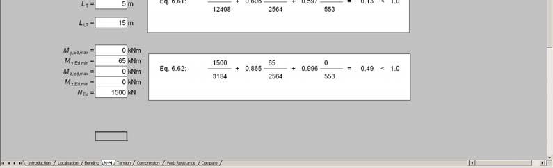
13 Buckling length The calculated resistance that is displaed is the design value of the lateral torsional buckling (LTB) resistance in knm. The figure shows a cross-section of the selected section, to scale, and the main geometric properties..5 N-M (combined axial force and bending moment) Worksheet The following data ma be selected: Section tpe Section data is included for the following section tpes (profiles): IPE HD HE HL Section All the standard sections within each section tpe are available for selection from the drop-down menu. Beam grade The steel grade for the beams ma be selected from the following: S35 S75 S355 S460 The internal moments and forces Maximum bending moment about the major axis, M,Ed,max Minimum bending moment about the major axis, M,Ed,min Maximum bending moment about the minor axis, M,Ed,max Minimum bending moment about the minor axis, M,Ed,min Axial force, N Ed Buckling lengths Major axis buckling length, L Minor axis buckling length, L Torsional buckling length, L T Lateral torsional buckling length, L LTB Choice of Annex A or Annex B The result that is displaed is the unit factor from the interaction equations 6.6 and 6.6 from EN and according to the chosen National Annex. 8-5
14 .6 Tension Worksheet The following data ma be selected: Section tpe Section data is included for the following section tpes (profiles): IPE HE UPE Equal Angles Unequal Angles (long leg attached) Unequal Angles (short leg attached) Section All the standard sections within each section tpe are available for selection from the drop-down menu. Beam grade The steel grade for the beams ma be selected from the following: S35 S75 S355 S460 Number of bolts When designing an angle, the number of bolts ma be selected from the following : No bolt (weld) bolt bolts 3 bolts Bolt sie The bolt sie ma be selected from the following: M M4 M6 M8 M0 M M4 M7 8-6
15 The output is the tension resistance, calculated as the resistance of the gross section at ield for I sections or the minimum resistance of the gross section at ield and the net section at ultimate for angles, all given in kn. The top figure shows a cross-section of the selected section, to scale and the main geometric properties. The bottom figure shows the bolted detail, onl when angle sections are selected..7 Compression Worksheet The following data ma be selected: Section tpe Section data is included for the following section tpes (profiles): IPE HD HE HL UPE Equal Angles Unequal Angles Section All the standard sections within each section tpe are available for selection from the drop-down menu. Beam grade The steel grade for the beams ma be selected from the following: S35 S75 S355 S460 Buckling lengths Major axis buckling length, L Minor axis buckling length, L Torsional buckling length, L T The calculated resistances are the design values of compression resistance, for flexural buckling resistance about the major axis and the minor axis (N b,,rd and N b,,rd ) as well as the torsional buckling resistance (N b,t,rd ), all given in kn for the relevant buckling lengths. In addition, the worksheet displas the minimum of these values. The figure shows a cross-section of the selected section, to scale and the main geometric properties. 8-7
16 .8 Web resistance (bearing and buckling) Worksheet The following data ma be selected: Section tpe Section data is included for the following section tpes (profiles): IPE HD HE HL UPE Section All the standard sections within each section tpe are available for selection from the drop-down menu. Beam grade The steel grade for the beams ma be selected from the following: S35 S75 S355 S460 Position of the transverse load d: distance from the end of the load to the member end. s s : stiff bearing length. The output is the web bearing and buckling resistance, calculated as per EN , given in kn. The top figure shows a cross-section of the selected section, to scale and the main geometric properties. The bottom figure shows the detail of the transverse load with respect to the end of the member..9 Compare worksheet The compare worksheet will displa in a single line the main details of the resistance calculated. This sheet also shows an previousl added calculations for an members, so it serves as a summar of all calculations. Additional calculations can be added to this worksheet b selecting the Add to comparison file button on an other member resistance worksheets (see section.3.). Note that the compare worksheet is hidden if no details have been added to comparison file. 8-8
17 .9. Print comparison file This button formats the comparison file and opens up the print window, where the user can select a printer and print. 8-9


18 3 SCREENSHOTS Figure 3. Introduction worksheet Figure 3. Localisation worksheet 8-0


19 Figure 3.3 Bending worksheet Figure 3.4 N-M worksheet 8 -
20 Figure 3.5 Tension worksheet Figure 3.6 Compression worksheet 8 -

21 Figure 3.7 Web resistance worksheet Figure 3.8 Compare worksheet 8-3
22 8-4
23 APPENDIX A Worked Examples The worked examples show the design procedure used b the member resistance calculator for members in multi-store building according to the Eurocodes. The worked examples cover different tpe of designs:. Bending moment resistance Supplementar calculations to demonstrate the influence of the French National Annex. Combined axial force and bending moment (N-M interaction) 3. Tension resistance 4. Compression resistance 5. Web resistance Note that supplementar calculations are included to show that the influence of the French National Annex has been incorporated into the calculation routines. 8-5
24 Worked Example : Bending moment resistance of 3 Calculation sheet Made b CZT Date 0/00 Checked b ENM Date 0/00. Bending moment resistance This example presents the method used in the member resistance calculator for calculating the bending moment resistance, adopting the recommended values of EN Section: IPE 500 Steel grade: S355 L 3,8 m References are to EN unless otherwise stated.. Cross-section classification... The web c 46 Table 5. 4,8 (Sheet ) 0, t w The limit for Class is : 7ε 7 0,8 58,3 c Then : 4,8 < 58,3 t w The web is class.... The flange c 73, 69 t f 4,6 The limit for Class is : 9ε 9 0,8 7,3 c Then : 4,6 < 8,3 t f The flange is Class Therefore the section is Class. The verification of the member will be based on the plastic resistance of the cross-section. Table 5. (Sheet ).. Lateral-torsional buckling resistance, M b,rd 444 knm C, Appendix C of Single-Store Steel Building, Part 4 8-6
25 Title Worked Example: Bending moment resistance of 3 M cr C EI L I I w L GI t EI, M cr Nmm LT W M f cr For hot rolled sections , LT,5 LT LT LT, LT,0 0,4 and 0,75 h b,5 Curve c for hot rolled I sections LT 0,49 LT,5 0,490,708 0,4 LT 0,708 LT 0 LT 0,75 0,708 0,763 LT LT 4 Appendix C of Single-Store Steel Building, Part Table 6.3 Table LT 0,763 0,763 0,75 0,708,99 LT 0,708 Therefore LT 0,8 f 0,5 ( - k c ) [,0 ( LT 0,8) ] k c 0,75,33 0,33,33 0,33 0 0,8 f 0,5 ( 0,75) [,0 (0,708 0,8) ] 0,877 LT 0,8 χ LT mod 0, 937 f 0,877 M b,rd LT W pl, M f 3 0, , knm 8-7
26 Title Worked Example: Bending moment resistance 3 of 3 The French National Annex requires alternative values for LT,0, LT and. The revised calculations are demonstrated below. b LT,0 0, 0, 0, 0, 0,4 h,5,0 b LT 0,4 0, LT 0,4 0, 0, 708 h,5 LT,5 0,360,708 0,4 LT 0 0,835 0,708 0,835 0,835 0,708 LT 0,783 χ LT mod 0, 89 f 0,877 0,783 0,36 French NA French NA French NA M b,rd,0 3 0, knm 8-8
27 Worked Example : Combined axial force and bending moment (N-M Interaction) of 5 Calculation sheet Made b CZT Date 0/00 Checked b ENM Date 0/00. Combined axial force and bending moment This example presents the method used in the member resistance calculator for calculating the out-of-plane buckling resistance and in-plane buckling resistance, adopting the recommended values of EN Section: IPE 450 Steel grade: S355 N Ed 7 kn M,Ed 356 knm (bending moment constant along the beam) M,Ed 0 knm L L L LT L cr,7 m References are to EN unless otherwise stated.. Cross-section classification... The web c 378,8 40,3 9, 4 t w Table 5. (Sheet ) d N t N w Ed f , d w d N 378,8 38 0,55 > 0,50 d w 378,8 396 The limit between Class and Class is : ,8 3 0,55 5, Then : c 40,3 < 5, t w The web is class.... The flange c 69,3 4,7 t f 4, 6 The limit between Class and Class is : 9 ε 9 0,8 7,3 c Then : 4,7 < 7,3 t f Table 5. (Sheet ) The flange is Class Therefore, the section is Class. The verification of the member will be based on the plastic resistance of the cross-section. 8-9
28 Title Worked Example: Axial compression and bending interaction (N-M Interaction) of 5.. Buckling verification The buckling checks due to the interaction of axial compression and bending moment are carried out using expressions 6.6 and 6.6 from EN N N Ed M N N Ed M Rk Rk k k M M,Ed LT,Ed LT M M,Rk M M M,Rk M,Ed,Ed k k M M,Ed,Ed M M M,Rk M M,Rk M,Ed,Ed,0,0 These expressions can be simplified as follows: M, Ed 0 and M, Ed 0 for Class, Class and Class 3 sections. M,Ed 0 Therefore expressions (6.6) and (6.6) can be written as: N N Ed b,,rd k M M,Ed b,rd N M Ed,Ed,0 and k, 0 N M b,,rd b,rd Expressions (6.6) and (6.6).3. Equation 6.6 (EN 993--).3.. Flexural buckling resistance about the major axis, N b,,rd h 450,37 b 90 t f 4,6 mm buckling about - axis: Curve a for hot rolled I sections 0, E ,4 f 355 L i cr 700 0, 85 76,4,5 0,,5 0, 0, 0 0, 0 0, 0,50 0,50 0,50 0,,0 Table 6. Table
29 Title Worked Example: Axial compression and bending interaction (N-M Interaction) 3 of 5 N b,,rd Af M, ,0 0 N Ed 7 kn < 3507 kn OK 3507 kn.3.. Lateral-torsional buckling resistance for bending, M b,rd In order to determine the critical moment of the rafter, the C factor takes account of the shape of the bending moment diagram. In this case the bending moment diagram is constant along the segment in consideration, so,0. Therefore: C,0 M cr C EI L,0 I I w L GI EI M cr Nmm LT W pl, M cr f t , LT 0,5 LT LT LT,0 LT LT,0 0,4 and 0,75 6 0,470 4 Appendix C of Single-Store Steel Building, Part 4 Appendix C of Single-Store Steel Building, Part h,37 b Curve c for hot rolled I sections LT 0,49 0,5 0,49 0,470 0,4 0,75 0, 0,60 LT 470 LT LT LT LT Table 6.3 Table LT LT 0,60 0,470 0,60 4,53 Therefore LT 0,96 0,75 0,470 0,96 8 -
30 Title Worked Example: Axial compression and bending interaction (N-M Interaction) 4 of 5 M b,rd LT W pl, M f M Ed 356 knm < 58 knm 3 0, , knm OK.3.3. Interaction of axial force and bending moment The interaction factor, k, is calculated as follows: k min C 0, N ; C 0, Ed m m 8 N b,,rd The expression for C m depends on the values of h and.,0. Therefore C m is calculated as: C m 0,6 + 0,4 ψ 0,4 + 0,4,0,0 7 7 k min,0 0, 0, ;,0 0,8 N N 3507 min [0,997;,09] 0,997 Ed b,,rd M,Ed k M b,rd 3507 N N Ed b,,rd ,997 0,647 <,0 OK Annex B Table B.3 Annex B Table B. The member satisfies the in-plane buckling check..4. Expression 6.6 (EN 993--).4.. Flexural buckling resistance about minor axis bending, N b,,rd h 450,37 b 90 t f 4,6 mm buckling about - axis Curve b for hot rolled I sections 0,34 E ,4 f 355 L i cr 700 0,540 4, 76,4,5 0,,5 0,34 0, , 0 0,540 0,704 Table 6. Table
31 Title Worked Example: Axial compression and bending interaction (N-M Interaction) 5 of 5 N b,,rd Af M 0,704 0,704 0, ,0 N Ed 7 kn < 3034 kn OK 0 0, kn 0, Interaction of axial force and bending moment 6.3.3(4) The interaction factor, k is calculated as follows: For 0,4 : k max 0, N Ed ; 0, C mlt 0,5 N b,,rd C mlt 0, 5 N b,,rd The bending moment is linear and constant. Therefore C mlt is,0. 0, 0,540 7 k max ; 3034 max (0,997, 0,994) 0,997 N N Ed b,,rd M,Ed k M 0, 0,5 0,5 b,rd ,997 0,653 <,0 OK N Ed Annex B Table B.3 Annex B Table B. 8-3
32 Worked Example 3: Tension Resistance of Calculation sheet Made b CZT Date 0/00 Checked b ENM Date 0/00. Tension Resistance This example presents the method used in the member resistance calculator for calculating the tension resistance, adopting the recommended values of the EN p p References are to EN unless otherwise stated Section: L 0 80 Steel grade: S35 Area: A 70 mm Bolts: M0, grade 8.8 Spacing between bolts p 70 mm Total number of bolts n 3 Diameter of the holes d 0 mm Partial safet factors M0,0 M,5 (for shear resistance of bolts).. Angle in tension 3 A N Rd net M f u,5 d 0,5 55 mm 5 d mm,5 d 0 < p < 5 d 0 3 can be determined b linear interpolation: Therefore 3 0, Table 3.8 A net A t ac d , Rd mm N 34 kn,5 8-4
33 Worked Example 4: Compression Resistance of 3 Calculation sheet Made b CZT Date 0/00 Checked b ENM Date 0/00. Compression Resistance This example presents the method used in the member resistance calculator for calculating the flexural and the torsional buckling resistance of members subject to pure compression, adopting the recommended values of EN Section: IPE 500 Steel grade: S35 L 3,8 m L 3,8 m References are to EN unless otherwise stated.. Cross-section classification... The web c 46 Table 5. 4,8 (Sheet ) 0, t w The limit between Class 3 and Class 4 is : 4ε 4,0 4 c Then : 4,8 < 4 t w The web is class The flange c 73, 69 t f 4,6 The limit between Class and Class is : 9ε 9,0 9 c Then : 4,6 < 9 t f The flange is Class. Therefore the section is Class 3. Table 5. (Sheet ).. Flexural buckling resistance about the major axis, N b,,rd L 3,8 m h 500 b 00 t f 6 mm,5 Buckling about - axis: 8-5
34 Title Worked Example: Compression Resistance of 3 Curve a for hot rolled I sections 0, E f L i cr , , ,9,5 0,,5 0, 0,98 0 0, 0 0,98 0,59 0,59 0,59 0,98,0 Table 6. Table N b,,rd χ Af M, , kn.3. Flexural buckling resistance about the minor axis, N b,,rd L 3,8 m h 500 b 00 t f 6 mm,5 Buckling about - axis: Curve b for hot rolled I sections 0, E f L i cr,5 0,,5 0,34 0, , ,94 43, 93,9 0 0, 0 N b,,rd 0,94,07 Af M,07,07 0,94 0, ,0 0 0,63 73 kn Table 6. Table
35 Title Worked Example: Compression Resistance 3 of 3.4. Torsional buckling N b,t,rd L T 3,8 m N crt EI i0 LT w GI i 0 i + i , N crt T , kn T A N f crt ,686 T 0,5 [ + α T ( T 0,) + ] T The buckling curve for torsional buckling is the same as for minor axis buckling, therefore choose buckling curve b α 0,34 T 0,5 ( + 0,34 (0,686-0,) + 0,686 ] 0,88 χ T T 0,88 0,88 0,686 0,79 N b,t,rd Af T M 0, kn,0 8-7
36 Worked Example 5: Web Resistance of Calculation sheet Made b CZT Date 0/00 Checked b ENM Date 0/00. Web Resistance This example presents the method used in the member resistance calculator for calculating the web resistance and the shear resistance, adopting the recommended values of the EN and EN Section: IPE 500 Steel grade: S355 c s s 0 mm 00 mm.. Shear resistance In the absence of torsion, the shear plastic resistance depends on the shear area, which is given b: A v A b t f + (t w + r) t f EN A v (0, + ) mm 6..6 (3) V pl,rd V pl,rd c A v f 3 M0 37 kn , kn.. Design resistance to local buckling s s 0 mm 00 mm b f 00 m 9, 6 t 0, w EN () h w m 0,0 tf if F 0, 5 m 0 if F 0, 5 First assume that F 0, m 0,0 6 7, ss c k F + 6 hw 00 0 k F but k F 6 8-8
37 Title Worked Example: Web Resistance and Shear Resistance of k F 3,4 < 6 l e k F E t f h w w but s s + c EN Eq (6.3) l e therefore l e 0 3, , l s s + t f m m ,6 7, 35 mm EN Eq (6.0) EN Eq (6.) m e l l e + t f m 9,6 0 t , f 6 48 mm l 3 l e + t f m m ,6 7, 07 mm EN Eq (6.) min (l ; l ; l 3 ) min (35; 48; 07) 07 mm l 3 tw F cr 0,9 k F E 0.9 3, hw 0, N 468 F t F w cr f 07 0, ,7 F, 7 0 > 0,5 Therefore the initial assumption was correct and the web resistance can be calculated based on this value of F. Should the calculated value of F be less than 0,5 then the calculation would need to be carried out again, using the appropriate expression for M χ F 0,5 F χ F 0,69 0,5 0,7 0,69 L eff L eff F Rd χ F l 0, mm f L eff M t w ,,0 58 kn EN () 8-9
STEEL BUILDINGS IN EUROPE. Multi-Storey Steel Buildings Part 10: Technical Software Specification for Composite Beams
 STEEL BUILDINGS IN EUROPE Multi-Storey Steel Buildings Part 10: Technical Software Specification for Composite Beams Multi-Storey Steel Buildings Part 10: Technical Software Specification for Composite
Made by SMH Date Aug Checked by NRB Date Dec Revised by MEB Date April 2006
 Job No. OSM 4 Sheet 1 of 8 Rev B Telephone: (0144) 45 Fax: (0144) 944 Made b SMH Date Aug 001 Checked b NRB Date Dec 001 Revised b MEB Date April 00 DESIGN EXAMPLE 9 - BEAM WITH UNRESTRAINED COMPRESSION
Structural Steelwork Eurocodes Development of A Trans-national Approach
 Structural Steelwork Eurocodes Development of A Trans-national Approach Course: Eurocode Module 7 : Worked Examples Lecture 0 : Simple braced frame Contents: 1. Simple Braced Frame 1.1 Characteristic Loads
STEEL MEMBER DESIGN (EN :2005)
") GEODOMISI Ltd. - Dr. Costas Sachpazis Consulting Company for App'd by STEEL MEMBER DESIGN (EN1993-1-1:2005) In accordance with EN1993-1-1:2005 incorporating Corrigenda February 2006 and April details type;
GEODOMISI Ltd. - Dr. Costas Sachpazis Consulting Company for App'd by STEEL MEMBER DESIGN (EN1993-1-1:2005) In accordance with EN1993-1-1:2005 incorporating Corrigenda February 2006 and April details type;
Eurocode 3 for Dummies The Opportunities and Traps
 Eurocode 3 for Dummies The Opportunities and Traps a brief guide on element design to EC3 Tim McCarthy Email tim.mccarthy@umist.ac.uk Slides available on the web http://www2.umist.ac.uk/construction/staff/
Structural Steelwork Eurocodes Development of A Trans-national Approach
 Structural Steelwork Eurocodes Development of A Trans-national Approach Course: Eurocode 3 Module 7 : Worked Examples Lecture 20 : Simple braced frame Contents: 1. Simple Braced Frame 1.1 Characteristic
Advanced Analysis of Steel Structures
 Advanced Analysis of Steel Structures Master Thesis Written by: Maria Gulbrandsen & Rasmus Petersen Appendix Report Group B-204d M.Sc.Structural and Civil Engineering Aalborg University 4 th Semester Spring
Made by PTY/AAT Date Jan 2006
 Job No. VALCOSS Sheet of 9 Rev A P.O. Box 000, FI-0044 VTT Tel. +358 0 7 Fax +358 0 7 700 Design Example 3 Stainless steel lattice girder made Made by PTY/AAT Date Jan 006 RFCS Checked by MAP Date Feb
Job No. Sheet 1 of 7 Rev A. Made by ER/EM Date Feb Checked by HB Date March 2006
 Job No. Sheet of 7 Rev A Design Example Design of a lipped channel in a Made by ER/EM Date Feb 006 Checked by HB Date March 006 DESIGN EXAMPLE DESIGN OF A LIPPED CHANNEL IN AN EXPOSED FLOOR Design a simply
Structural Steelwork Eurocodes Development of A Trans-national Approach
 Structural Steelwork Eurocodes Development of A Trans-national Approach Course: Eurocode Module 7 : Worked Examples Lecture 22 : Design of an unbraced sway frame with rigid joints Summary: NOTE This example
Steel Frame Design Manual
 Steel Frame Design Manual Eurocode 3-1:2005 with 8:2004 Eurocode 3-1:2005 with Eurocode 8:2004 Steel Frame Design Manual for ETABS 2016 ISO ETA122815M13 Rev 0 Proudly developed in the United States of
APOLLO SCAFFOLDING SERVICES LTD SPIGOT CONNECTION TO EUROCODES DESIGN CHECK CALCULATIONS
 Alan White Design APOLLO SCAFFOLDING SERVICES LTD SPIGOT CONNECTION TO EUROCODES DESIGN CHECK CALCULATIONS Alan N White B.Sc., M.Eng., C.Eng., M.I.C.E., M.I.H.T. JUL 2013 Somerset House 11 Somerset Place
JointsForTekla Ver January
 Ing. Giovanni Conticello Ing. Sebastiano Floridia With the important help of Ing. Giovanni Trigili JointsForTekla Ver. 1.11.0.59 - January 23 2014 Design of joints of steel structures in environment TeklaStructures
Job No. Sheet 1 of 6 Rev B. Made by IR Date Oct Checked by FH/NB Date Oct Revised by MEB Date April 2006
 Job No. Sheet 1 of 6 Rev B, Route de Limours Tel : (0)1 0 85 5 00 Fax : (0)1 0 5 75 8 Revised by MEB Date April 006 DESIGN EXAMPLE 6 BOLTED JOINT A 0 0 angle loaded in tension is to be connected to a gusset
C6 Advanced design of steel structures
 C6 Advanced design of steel structures prepared b Josef achacek List of lessons 1) Lateral-torsional instabilit of beams. ) Buckling of plates. 3) Thin-walled steel members. 4) Torsion of members. 5) Fatigue
3. Stability of built-up members in compression
 3. Stability of built-up members in compression 3.1 Definitions Build-up members, made out by coupling two or more simple profiles for obtaining stronger and stiffer section are very common in steel structures,
1C8 Advanced design of steel structures. prepared by Josef Machacek
 1C8 Advanced design of steel structures prepared b Josef achacek List of lessons 1) Lateral-torsional instabilit of beams. ) Buckling of plates. 3) Thin-walled steel members. 4) Torsion of members. 5)
Application nr. 3 (Ultimate Limit State) Resistance of member cross-section
 Resistance of member cross-section") Application nr. 3 (Ultimate Limit State) Resistance of member cross-section 1)Resistance of member crosssection in tension Examples of members in tension: - Diagonal of a truss-girder - Bottom chord of
Application nr. 3 (Ultimate Limit State) Resistance of member cross-section 1)Resistance of member crosssection in tension Examples of members in tension: - Diagonal of a truss-girder - Bottom chord of
Lateral Torsional Buckling (sections class 1-3) - Column Item COx
 - Column Item COx") Page /7 Lateral Torsional Buckling (sections class -3) - according to EN 993--:005 (EC3) section and eqn. numbers refer to this code (Form EC3-LTB_06-04-8.mcd - adopted) Profile chosen Profile "HEA40"
Page /7 Lateral Torsional Buckling (sections class -3) - according to EN 993--:005 (EC3) section and eqn. numbers refer to this code (Form EC3-LTB_06-04-8.mcd - adopted) Profile chosen Profile "HEA40"
DIF SEK. PART 5a WORKED EXAMPLES. DIFSEK Part 5a: Worked examples 0 / 62
 DIF SEK PART 5a WORKED EXAMPLES DIFSEK Part 5a: Worked examples 0 / 62 Resistance to fire - Chain of events Θ Loads 1: Ignition time Steel columns 2: Thermal action 3: Mechanical actions R 4: Thermal response
Fundamentals of Structural Design Part of Steel Structures
 Fundamentals of Structural Design Part of Steel Structures Civil Engineering for Bachelors 133FSTD Teacher: Zdeněk Sokol Office number: B619 1 Syllabus of lectures 1. Introduction, history of steel structures,
Made by SMH Date Aug Checked by NRB Date Nov Revised by MEB Date April 2006
 Job o. OS 466 Sheet of 8 Rev B Silwood Par, Ascot, Bers SL5 7Q Telephone: (0344) 63345 Fax: (0344) 6944 CALCULATIO SHEET Design Example 0 Axiall loaded column in fire ade b SH Date Aug 00 Checed b RB Date
Design of Beams (Unit - 8)
") Design of Beams (Unit - 8) Contents Introduction Beam types Lateral stability of beams Factors affecting lateral stability Behaviour of simple and built - up beams in bending (Without vertical stiffeners)
Design of Beams (Unit - 8) Contents Introduction Beam types Lateral stability of beams Factors affecting lateral stability Behaviour of simple and built - up beams in bending (Without vertical stiffeners)
Workshop 8. Lateral Buckling
 Workshop 8 Lateral Buckling cross section A transversely loaded member that is bent about its major axis may buckle sideways if its compression flange is not laterally supported. The reason buckling occurs
University of Sheffield. Department of Civil Structural Engineering. Member checks - Rafter 44.6
 Member checks - Rafter 34 6.4Haunch (UB 457 x 191 x 89) The depth of a haunch is usually made approximately twice depth of the basic rafter sections, as it is the normal practice to use a UB cutting of
SECTION 7 DESIGN OF COMPRESSION MEMBERS
 SECTION 7 DESIGN OF COMPRESSION MEMBERS 1 INTRODUCTION TO COLUMN BUCKLING Introduction Elastic buckling of an ideal column Strength curve for an ideal column Strength of practical column Concepts of effective
Design of Steel Structures Prof. S.R.Satish Kumar and Prof. A.R.Santha Kumar
 5.4 Beams As stated previousl, the effect of local buckling should invariabl be taken into account in thin walled members, using methods described alread. Laterall stable beams are beams, which do not
LOAD BEARING CAPACITY OF SPLICED COLUMNS WITH SINGLE ROW BOLTED BUTT-PLATES
 LOAD BEARING CAPACITY OF SPLICED COLUMNS WITH SINGLE ROW BOLTED BUTT-PLATES J.C.D. Hoenderkamp, H. H. Snijder Eindhoven University of Technology, The Netherlands j.c.d.hoenderkamp@tue.nl h.h.snijder@tue.nl
Finite Element Modelling with Plastic Hinges
 01/02/2016 Marco Donà Finite Element Modelling with Plastic Hinges 1 Plastic hinge approach A plastic hinge represents a concentrated post-yield behaviour in one or more degrees of freedom. Hinges only
Example 4: Design of a Rigid Column Bracket (Bolted)
") Worked Example 4: Design of a Rigid Column Bracket (Bolted) Example 4: Design of a Rigid Column Bracket (Bolted) Page : 1 Example 4: Design of a Rigid Column Bracket (Bolted) Determine the size of the
Worked Example 4: Design of a Rigid Column Bracket (Bolted) Example 4: Design of a Rigid Column Bracket (Bolted) Page : 1 Example 4: Design of a Rigid Column Bracket (Bolted) Determine the size of the
Design Beam Flexural Reinforcement
 COPUTERS AND STRUCTURES, INC., BERKELEY, CALIFORNIA DECEBER 2001 CONCRETE FRAE DESIGN ACI-318-99 Technical Note This Technical Note describes how this program completes beam design when the ACI 318-99
Design of Compression Members
 Design of Compression Members 2.1 Classification of cross sections Classifying cross-sections may mainly depend on four critical factors: 1- Width to thickness (c/t) ratio. 2- Support condition. 3- Yield
DESIGN OF BEAM-COLUMNS - II
 DESIGN OF BEA-COLUNS-II 14 DESIGN OF BEA-COLUNS - II 1.0 INTRODUCTION Beam-columns are members subjected to combined bending and axial compression. Their behaviour under uniaxial bending, biaxial bending
Job No. Sheet No. Rev. CONSULTING Engineering Calculation Sheet. Member Design - Steel Composite Beam XX 22/09/2016
 CONSULTING Engineering Calculation Sheet jxxx 1 Member Design - Steel Composite Beam XX Introduction Chd. 1 Grade 50 more common than Grade 43 because composite beam stiffness often 3 to 4 times non composite
7.3 Design of members subjected to combined forces
 7.3 Design of members subjected to combined forces 7.3.1 General In the previous chapters of Draft IS: 800 LSM version, we have stipulated the codal provisions for determining the stress distribution in
Interactive Buckling of Cold-Formed Steel Sections Applied in Pallet Rack Upright Members
 Interactive Buckling of Cold-Formed Steel Sections Applied in Pallet Rack Upright Members D. Dubina, V. Ungureanu, A. Crisan Politehnica University of Timişoara Peculiarities of cold-formed thin-walled
Application nr. 7 (Connections) Strength of bolted connections to EN (Eurocode 3, Part 1.8)
 Strength of bolted connections to EN (Eurocode 3, Part 1.8)") Application nr. 7 (Connections) Strength of bolted connections to EN 1993-1-8 (Eurocode 3, Part 1.8) PART 1: Bolted shear connection (Category A bearing type, to EN1993-1-8) Structural element Tension
Application nr. 7 (Connections) Strength of bolted connections to EN 1993-1-8 (Eurocode 3, Part 1.8) PART 1: Bolted shear connection (Category A bearing type, to EN1993-1-8) Structural element Tension
MS Excel Toolkit: Design of steel-concrete composite columns in accordance with EN
 MS Excel Toolkit: Design of steel-concrete composite columns in accordance with EN 1994-1-1 Guilherme de Azevedo Guedes Lebre Dissertation in Civil Engineering, Master Degree Instituto Superior Técnico,
A Parametric Study on Lateral Torsional Buckling of European IPN and IPE Cantilevers H. Ozbasaran
 Vol:8, No:7, 214 A Parametric Study on Lateral Torsional Buckling of European IPN and IPE Cantilevers H. Ozbasaran Abstract IPN and IPE sections, which are commonly used European I shapes, are widely used
Structural Steelwork Eurocodes Development of a Trans-National Approach
 Course: Eurocode 4 Structural Steelwork Eurocodes Development of a Trans-National Approach Lecture 9 : Composite joints Annex B References: COST C1: Composite steel-concrete joints in frames for buildings:
DESIGN GUIDES FOR HIGH STRENGTH STRUCTURAL HOLLOW SECTIONS MANUFACTURED BY SSAB - FOR EN 1090 APPLICATIONS
 DESIGN GUIDES FOR HIGH STRENGTH STRUCTURAL HOLLOW SECTIONS MANUFACTURED BY SSAB - FOR EN 1090 APPLICATIONS SSAB produces a wide variety of hollow sections in different steel grades according to European
Metal Structures Lecture XIII Steel trusses
 Metal Structures Lecture XIII Steel trusses Contents Definition #t / 3 Geometry and cross-sections #t / 7 Types of truss structures #t / 15 Calculations #t / 29 Example #t / 57 Results of calculations
9-3. Structural response
 9-3. Structural response in fire František Wald Czech Technical University in Prague Objectives of the lecture The mechanical load in the fire design Response of the structure exposed to fire Levels of
A. Ideal beam without imperfections: Critical moment M cr
 Beam in bending: Ideal beam without imperfections: characteristic is critical moment M cr Real beam with imperfections characteristic is resistance of beam M b,rd A. Ideal beam without imperfections: Critical
VALLOUREC & MANNESMANN TUBES. Design-support for MSH sections
 VALLOUREC & MANNESMANN TUBES Design-support for MSH sections according to Eurocode 3, DIN EN 1993-1-1: 2005 and DIN EN 1993-1-8: 2005 Design-Support for MSH sections according to Eurocode 3, DIN EN 1993-1-1:
Influence of residual stresses in the structural behavior of. tubular columns and arches. Nuno Rocha Cima Gomes
 October 2014 Influence of residual stresses in the structural behavior of Abstract tubular columns and arches Nuno Rocha Cima Gomes Instituto Superior Técnico, Universidade de Lisboa, Portugal Contact:
A Simplified Method for the Design of Steel Beam-to-column Connections
 P P Periodica Polytechnica Architecture A Simplified Method for the Design of Steel Beam-to-column Connections 48() pp. 79-86 017 https://doi.org/10.3311/ppar.11089 Creative Commons Attribution b Imola
DESIGN OF BEAMS AND SHAFTS
 DESIGN OF EAMS AND SHAFTS! asis for eam Design! Stress Variations Throughout a Prismatic eam! Design of pristmatic beams! Steel beams! Wooden beams! Design of Shaft! ombined bending! Torsion 1 asis for
Bridge deck modelling and design process for bridges
 EU-Russia Regulatory Dialogue Construction Sector Subgroup 1 Bridge deck modelling and design process for bridges Application to a composite twin-girder bridge according to Eurocode 4 Laurence Davaine
On Design Method of Lateral-torsional Buckling of Beams: State of the Art and a New Proposal for a General Type Design Method
 Ŕ Periodica Polytechnica Civil Engineering 59(2), pp. 179 192, 2015 DOI: 10.3311/PPci.7837 Creative Commons Attribution RESEARCH ARTICLE On Design Method of Lateral-torsional Buckling of Beams: State of
Design of Steel Structures Prof. Damodar Maity Department of Civil Engineering Indian Institute of Technology, Guwahati
 Design of Steel Structures Prof. Damodar Maity Department of Civil Engineering Indian Institute of Technology, Guwahati Module 7 Gantry Girders and Plate Girders Lecture - 3 Introduction to Plate girders
TORSION INCLUDING WARPING OF OPEN SECTIONS (I, C, Z, T AND L SHAPES)
") Page1 TORSION INCLUDING WARPING OF OPEN SECTIONS (I, C, Z, T AND L SHAPES) Restrained warping for the torsion of thin-wall open sections is not included in most commonly used frame analysis programs. Almost
Page1 TORSION INCLUDING WARPING OF OPEN SECTIONS (I, C, Z, T AND L SHAPES) Restrained warping for the torsion of thin-wall open sections is not included in most commonly used frame analysis programs. Almost
COMPARISON BETWEEN BS 5950: PART 1: 2000 & EUROCODE 3 FOR THE DESIGN OF MULTI-STOREY BRACED STEEL FRAME CHAN CHEE HAN
 i COMPARISON BETWEEN BS 5950: PART 1: 2000 & EUROCODE 3 FOR THE DESIGN OF MULTI-STOREY BRACED STEEL FRAME CHAN CHEE HAN A project report submitted as partial fulfillment of the requirements for the award
Effective stress method to be used in beam finite elements to take local instabilities into account
 Effective stress method to be used in beam finite elements to take local instabilities into account JEAN-MARC FRANSSEN, BAPTISTE COWEZ and THOMAS GERNAY ArgencoDepartment University of Liège Chemin des
1C8 Advanced design of steel structures. prepared by Josef Machacek
 1C8 Advanced design of steel structures prepared b Josef Machacek List of lessons 1) Lateral-torsional instabilit of beams. ) Buckling of plates. 3) Thin-alled steel members. ) Torsion of members. 5) Fatigue
Advanced Training Aluminium
 Advanced Training Aluminium Aluminium Code Check All information in this document is subject to modification without prior notice. No part of this manual may be reproduced, stored in a database or retrieval
Buckling Resistance Assessment of a Slender Cylindrical Shell Axially Compressed
 Mechanics and Mechanical Engineering Vol. 14, No. 2 (2010) 309 316 c Technical University of Lodz Buckling Resistance Assessment of a Slender Cylindrical Shell Axially Compressed Jakub Marcinowski Institute
BRACING MEMBERS SUMMARY. OBJECTIVES. REFERENCES.
 BRACING MEMBERS SUMMARY. Introduce the bracing member design concepts. Identify column bracing members requirements in terms of strength and stiffness. The assumptions and limitations of lateral bracing
CALCULATION MODE FOR ALUHD23/SH18 Traction and shear aluminium plate for Alufoot R system
 CALCULATION MODE FOR ALUHD23/SH18 Traction and shear aluminium plate for Alufoot R system INTRODUCTION ALUHD23/SH18 plate, being part of Alufoot system, is used in order to connect the CLT wall to the
Design of a Steel I-section for Bending, Shear and Axial Force
 Benchmark Example No. 20 Design of a Steel I-section for Bending, Shear and Axial Force SOFiSTiK 2018 VERiFiCATiON MANUAL DCE-EN20: Design of a Steel I-section for Bending, Shear and Axial Force VERiFiCATiON
Basis of Design, a case study building
 Basis of Design, a case study building Luís Simões da Silva Department of Civil Engineering University of Coimbra Contents Definitions and basis of design Global analysis Structural modeling Structural
SPECIFIC VERIFICATION Chapter 5
 As = 736624/(0.5*413.69) = 3562 mm 2 (ADAPT 3569 mm 2, B29, C6) Data Block 27 - Compressive Stresses The initial compressive strength, f ci, is the strength entered in the Material/Concrete input screen.
ADVANCED DESIGN OF STEEL AND COMPOSITE STRUCTURES
 ADVANCED DESIGN OF STEEL AND COMPOSITE STRUCTURES Aldina Santiago Lecture B.3: 22/2/2017 European Erasmus Mundus 520121-1-2011-1-CZ-ERA MUNDUS-EMMC CONTENTS Module B Design of industrial buildings using
An area chart emphasizes the trend of each value over time. An area chart also shows the relationship of parts to a whole.
 Excel 2003 Creating a Chart Introduction Page 1 By the end of this lesson, learners should be able to: Identify the parts of a chart Identify different types of charts Create an Embedded Chart Create a
Fire resistance assessment of composite steel-concrete structures
 Workshop Structural Fire Design of Buildings according to the Eurocodes Brussels, 78 November 0 Fire resistance assessment of composite steelconcrete structures Basic design methods Worked examples CAJOT
Advanced stability analysis and design of a new Danube archbridge. DUNAI, László JOÓ, Attila László VIGH, László Gergely
 Advanced stability analysis and design of a new Danube archbridge DUNAI, László JOÓ, Attila László VIGH, László Gergely Subject of the lecture Buckling of steel tied arch Buckling of orthotropic steel
Hilti North America Installation Technical Manual Technical Data MI System Version
 MIC-SA-MAH 174671 Hilti North America Installation Technical Manual Technical Data MI System Version 1. 08.017 Terms of common cooperation / Legal disclaimer The product technical data published in these
AXIAL BUCKLING RESISTANCE OF PARTIALLY ENCASED COLUMNS
 Proceedings of the 5th International Conference on Integrity-Reliability-Failure, Porto/Portugal 24-28 July 2016 Editors J.F. Silva Gomes and S.A. Meguid Publ. INEGI/FEUP (2016) PAPER REF: 6357 AXIAL BUCKLING
General Comparison between AISC LRFD and ASD
 General Comparison between AISC LRFD and ASD 1 General Comparison between AISC LRFD and ASD 2 AISC ASD and LRFD AISC ASD = American Institute of Steel Construction = Allowable Stress Design AISC Ninth
STRUCTURAL VERIFICATION OF A 60.7 M DOME ROOF FOR TANK FB 2110
 CTS Netherlands B.V. Riga 10 2993 LW Barendrecht The Netherlands Tel.: +31 (0)180 531027 (office) Fax: +31 (0)180 531848 (office) E-mail: info@cts-netherlands.com Website: www.cts-netherlands.com Chamber
Accordingly, the nominal section strength [resistance] for initiation of yielding is calculated by using Equation C-C3.1.
![Accordingly, the nominal section strength [resistance] for initiation of yielding is calculated by using Equation C-C3.1.](/thumbs/89/98617066.jpg "Accordingly, the nominal section strength [resistance] for initiation of yielding is calculated by using Equation C-C3.1.") C3 Flexural Members C3.1 Bending The nominal flexural strength [moment resistance], Mn, shall be the smallest of the values calculated for the limit states of yielding, lateral-torsional buckling and distortional
C3 Flexural Members C3.1 Bending The nominal flexural strength [moment resistance], Mn, shall be the smallest of the values calculated for the limit states of yielding, lateral-torsional buckling and distortional
twenty steel construction: columns & tension members ARCHITECTURAL STRUCTURES: FORM, BEHAVIOR, AND DESIGN DR. ANNE NICHOLS FALL 2013 lecture
 ARCHITECTURAL STRUCTURES: FORM, BEHAVIOR, AND DESIGN DR. ANNE NICHOLS Cor-Ten Steel Sculpture By Richard Serra Museum of Modern Art Fort Worth, TX (AISC - Steel Structures of the Everyday) FALL 2013 lecture
ADVANCED CONCEPT TRAINING
 ADVANCED CONCEPT TRAINING ALUMINIUM CODE CHECK Advanced Concept Training Aluminium Code Check All information in this document is subject to modification without prior notice. No part of this manual may
PLATE GIRDERS II. Load. Web plate Welds A Longitudinal elevation. Fig. 1 A typical Plate Girder
 16 PLATE GIRDERS II 1.0 INTRODUCTION This chapter describes the current practice for the design of plate girders adopting meaningful simplifications of the equations derived in the chapter on Plate Girders
ε t increases from the compressioncontrolled Figure 9.15: Adjusted interaction diagram
 CHAPTER NINE COLUMNS 4 b. The modified axial strength in compression is reduced to account for accidental eccentricity. The magnitude of axial force evaluated in step (a) is multiplied by 0.80 in case
APOLLO SALES LTD PUBLIC ACCESS SCAFFOLD STEP DESIGN CHECK CALCULATIONS
 Alan White Design APOLLO SALES LTD PUBLIC ACCESS SCAFFOLD STEP DESIGN CHECK CALCULATIONS Alan N White B.Sc., M.Eng., C.Eng., M.I.C.E., M.I.H.T. Feb 2014 Somerset House 11 Somerset Place GLASGOW G3 7JT
Formulation of Equivalent Steel Section for Partially Encased Composite Column under Concentric Gravity Loading
 Formulation of Equivalent Steel Section for Partially Encased Composite Column under Concentric Gravity Loading Debaroti Ghosh & Mahbuba Begum Dept of Civil Engineering, Bangladesh University of Engineering
Autodesk Robot Structural Analysis Professional 2014 Design of fixed beam-to-column connection EN :2005/AC:2009
 Autodesk Robot Structural Analysis Professional 2014 Design of fixed beam-to-column connection EN 1993-1-8:2005/AC:2009 Ratio 0,44 GENERAL Connection no.: 24 Connection name: Ligação 2 Structure node:
A.R. Tusnin, M. Prokic. Behavior of symmetric steel I-sections under combined bending and torsion actions in inelastic range
 A.R. Tusnin, M. Prokic Behavior of smmetric steel Isections under combined bending and torsion actions in inelastic range In European codes and Russian standards for design of steel structures, calculation
Design of a Steel I-section for Bending and Shear
 Benchmark Example No. 13 Design of a Steel I-section for Bending and Shear SOFiSTiK 2018 VERiFiCATiON MANUAL DCE-EN13: Design of a Steel I-section for Bending and Shear VERiFiCATiON MANUAL, Version 2018-7
TOPIC TRAINING CODE CHECK COLD-FORMED STEEL PROFILES
 TOPIC TRAINING CODE CHECK COLD-FORMED STEEL PROFILES All information in this document is subject to modification without prior notice. No part of this manual may be reproduced, stored in a database or
NATURAL PERIOD OF STEEL CHIMNEYS
 SDSS Rio 010 STABILITY AND DUCTILITY OF STEEL STRUCTURES E. Batista, P. Vellasco, L. de Lima (Eds.) Rio de Janeiro, Brazil, September 8-10, 010 NATURAL PERIOD OF STEEL CHIMNEYS Aleksander Kozlowski, Andrzej
GENERAL GEOMETRY LEFT SIDE BEAM RIGHT SIDE BS :2000/AC:2009. Ratio 0.17
 Autodesk Robot Structural Analysis Professional 2015 Design of fixed beam-to-beam connection BS 5950-1:2000/AC:2009 Ratio 0.17 GENERAL Connection no.: 2 Connection name: Beam-Beam Structure node: 40 Structure
UNIVERSITY OF AKRON Department of Civil Engineering
 UNIVERSITY OF AKRON Department of Civil Engineering 4300:401-301 July 9, 2013 Steel Design Sample Quiz 2 1. The W10 x 54 column shown has both ends pinned and consists of A992 steel (F y = 50 ksi, F u
An Increase in Elastic Buckling Strength of Plate Girder by the Influence of Transverse Stiffeners
 GRD Journals- Global Research and Development Journal for Engineering Volume 2 Issue 6 May 2017 ISSN: 2455-5703 An Increase in Elastic Buckling Strength of Plate Girder by the Influence of Transverse Stiffeners
Tangent pile wall check in Paratie Plus
 Tangent pile wall check in Paratie Plus Consider the example shown in the window above. It concerns a wall made up of pails featured this way: Section: 180 x 10 mm Material: Fe510 Horizontal space: 0,5
DESIGN OF FIXED CIRCULAR ARCHES WITH TUBE CROSS-SECTIONS UNDER CONCENTRATED LOADS ACCORDING TO EC3
 EUROSTEEL 8, 3-5 September 8, Graz, Austria 785 DESIGN OF FIXED CIRCULAR ARCHES WITH TUBE CROSS-SECTIONS UNDER CONCENTRATED LOADS ACCORDING TO EC3 C.A. Dimopoulos a, C.J. Gantes a a National Technical
Laboratory 4 Topic: Buckling
 Laboratory 4 Topic: Buckling Objectives: To record the load-deflection response of a clamped-clamped column. To identify, from the recorded response, the collapse load of the column. Introduction: Buckling
MODULE C: COMPRESSION MEMBERS
 MODULE C: COMPRESSION MEMBERS This module of CIE 428 covers the following subjects Column theory Column design per AISC Effective length Torsional and flexural-torsional buckling Built-up members READING:
Design of Steel Structures Prof. S.R.Satish Kumar and Prof. A.R.Santha Kumar
 7. BEAM COLUMNS 7.1 Introduction The Indian steel code is now in the process of revision as specification-based design gives way to performance-based design. An expert committee mainly comprising eminent
CHAPTER 4. Design of R C Beams
 CHAPTER 4 Design of R C Beams Learning Objectives Identify the data, formulae and procedures for design of R C beams Design simply-supported and continuous R C beams by integrating the following processes
Design of Steel Structures Prof. S.R.Satish Kumar and Prof. A.R.Santha Kumar
 5.10 Examples 5.10.1 Analysis of effective section under compression To illustrate the evaluation of reduced section properties of a section under axial compression. Section: 00 x 80 x 5 x 4.0 mm Using
REINFORCED CONCRETE DESIGN 1. Design of Column (Examples and Tutorials)
") For updated version, please click on http://ocw.ump.edu.my REINFORCED CONCRETE DESIGN 1 Design of Column (Examples and Tutorials) by Dr. Sharifah Maszura Syed Mohsin Faculty of Civil Engineering and Earth
For updated version, please click on http://ocw.ump.edu.my REINFORCED CONCRETE DESIGN 1 Design of Column (Examples and Tutorials) by Dr. Sharifah Maszura Syed Mohsin Faculty of Civil Engineering and Earth
DESIGN OF END PLATE JOINTS SUBJECT TO MOMENT AND NORMAL FORCE
 DESIGN OF END PLATE JOINTS SUBJECT TO OENT AND NORAL FORCE Zdeněk Sokol 1, František Wald 1, Vincent Delabre 2, Jean-Pierre ueau 2, arek Švarc 1 ABSTRACT The presented work describes design model of end
Plastic Design of Portal frame to Eurocode 3
 Department of Civil and Structural Engineering Plastic Design of Portal frame to Eurocode 3 Worked Example University of Sheffield Contents 1 GEOMETRY... 3 2 DESIGN BRIEF... 4 3 DETERMINING LOADING ON
A CONNECTION ELEMENT FOR MODELLING END-PLATE CONNECTIONS IN FIRE
 A CONNECTION ELEMENT OR MODELLING END-PLATE CONNECTIONS IN IRE Dr Zhaohui Huang Department of Civil & Structural Engineering, University of Sheffield 22 September 29 1. INTRODUCTION Three approaches for
Steel connections. Connection name : MEP_BCF_W=14.29[mm]_W=6.35[mm]_tp=63.5[mm]_N=0_N=2_N=0_N=1_W=14.29[mm]_W=14.29[mm]_W=14.29[ mm] Connection ID : 1
![Steel connections. Connection name : MEP_BCF_W=14.29[mm]_W=6.35[mm]_tp=63.5[mm]_N=0_N=2_N=0_N=1_W=14.29[mm]_W=14.29[mm]_W=14.29[ mm] Connection ID : 1](/thumbs/96/127718340.jpg "Steel connections. Connection name : MEP_BCF_W=14.29[mm]_W=6.35[mm]_tp=63.5[mm]_N=0_N=2_N=0_N=1_W=14.29[mm]_W=14.29[mm]_W=14.29[ mm] Connection ID : 1") Current Date: 08-Dec-13 7:05 PM Units system: SI File name: E:\ram\1\1.cnx\ Microsoft Steel connections Detailed report Connection name : MEP_BCF_W=14.29[mm]_W=6.35[mm]_tp=63.5[mm]_N=0_N=2_N=0_N=1_W=14.29[mm]_W=14.29[mm]_W=14.29[
Current Date: 08-Dec-13 7:05 PM Units system: SI File name: E:\ram\1\1.cnx\ Microsoft Steel connections Detailed report Connection name : MEP_BCF_W=14.29[mm]_W=6.35[mm]_tp=63.5[mm]_N=0_N=2_N=0_N=1_W=14.29[mm]_W=14.29[mm]_W=14.29[
1 Introduction Scope Normative references Terms and definitions Symbols Terminology and conventions for dimensions 8 2 B
 1 Introduction 5 1.1 Scope 5 1.2 Normative references 5 1.3 Terms and definitions 6 1.4 Symbols 7 1.5 Terminology and conventions for dimensions 8 2 Basis of design 11 3 Materials 12 3.1 General 12 3.2
Concrete Module. Concrete Module 1
 Concrete Module 1Introduction... 7 1.1 Generally... 7 1.2 Restrictions... 7 2 Program structure... 9 2.1 Concrete input... 9 2.1.1 Material - Concrete... 9 2.1.1.1 Material data... 10 2.1.1.2 Reinforcement
ENCE 455 Design of Steel Structures. III. Compression Members
 ENCE 455 Design of Steel Structures III. Compression Members C. C. Fu, Ph.D., P.E. Civil and Environmental Engineering Department University of Maryland Compression Members Following subjects are covered: