Concrete and Masonry Structures 1 Office hours
|
|
|
- Ophelia Mabel Paul
- 5 years ago
- Views:
Transcription
1 Concrete and Masonry Structures 1 Petr Bílý, office B731 Courses in English Concrete and Masonry Structures 1 Office hours
2 Credit receiving requirements General knowledge of design of concrete structures (e.g. 133FSTD Fundamentals of Structural Design) Working out of the homework assigned during the semester. Homework delivered: the next week 3 points 1 week delay 2 points 2 weeks delay 1 point 3 or more weeks delay 0 points, but you still have to deliver!!! Tests at the lectures max. 3 points each Reach at least 45 points out of total of 72 points (12 tests, 12 pieces of homework)

3 structures
4 Homework 7 tasks Page layout A4 onesided Write by pencil (easy to correct) M Ed = 1/8*f*L 2 M Ed = 1/8*8*5 2 M Ed = 25 knm 5 cm Load Char. γ F Design 1,35 1,50. TOTAL
5 Rules for structural analysis elaboration Well-arranged, clear, controllable Page numbers (cross reference to previous calculations and results) All calculations, assumptions write down in the analysis State formula substitute calculate results, quote units Calculation of loads in tables Sketches, figures
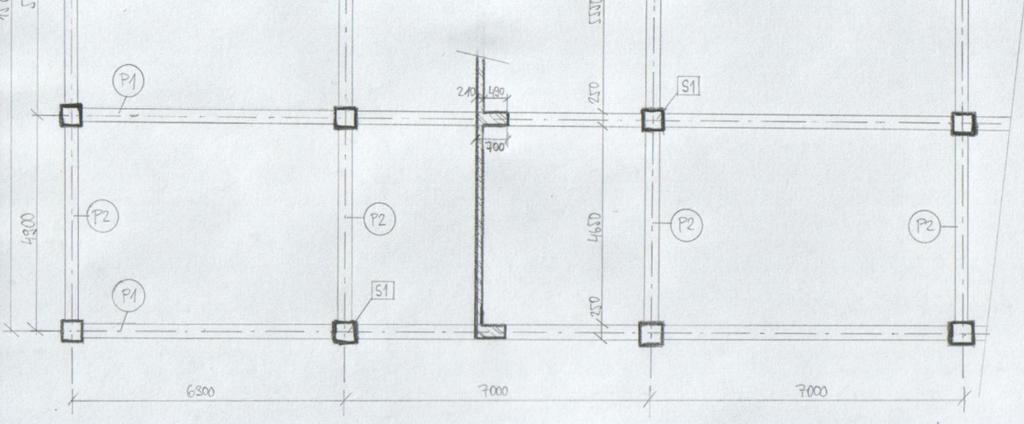
6 1st task: FrameStructure
7 Individual Parameters see excel spreadsheet R, a [m] distance of axes in the plan (spans) h [m] floor height n number of floors concrete class Permanent load (except self weight) for typical floor (gg 0 ) floor,k [kn/m 2 ] Permanent load (except self weight) for roof (g-g 0 ) roof,k [kn/m 2 ] Variable load for typical floor q floor,k [kn/m 2 ] Variable load for roof q k = 0,75 kn/m 2 Exposure class related to environmental conditions Design working life
8 Our goal will be to: Design dimensions of all elements Do detailed calculation of 2D frame - calculation of bending moments, shear and normal forces using FEM software Design frame reinforcement Draw layout of reinforcement
9 Design of dimensions Depth of the slab Dimensions of the beam Column dimensions Sketch of the structure
10 Depth of the slabh S One-way slab Empirical estimation: Effective depth d: hs 1 1 = d = h c s 2 l Diameter of steel bars, 10 mm Cover depth
11 Cover depth c c = c= c + c min c dev = 10 mm (technology allowance) c min,b = 10 mm (cover depth necessary for good mechanical bond between steel and concrete, equal to diameter of steel bars) c min,dur see table (cover depth necessary for good resistance to unfavourable effects of the environment) dev ( c c ) max ; ;10 mm min min,b min,dur
12
13 Depth of the slabh S Span/depth ratio (deflection control): See table, for slabs consider the value for 0,5 % reinf. ratio l λ = λ κ κ κ λ lim = d Effect of shape 1.0 c1 c2 c3 d,tab Effect of span 1.0 Effect of reinforcement 1.2 If λ λ min, detailed calculation of deflections may be omitted However, usually the slab is uneconomical if the condition is satisfied
14 for outer span of the continuous beam/slab Concrete class for inner span of the continuous beam/slab Concrete class
15 Depth of the slabh S Usually the slab is uneconomical if the span/depth condition is satisfied => just adjust the empirical design with respect to span/depth ratio If λ > λ min, increase the depth of the slab by some mm, depending on the difference between empirical design and design according to span/depth ratio
16 Design of the beam Empirical estimation hb = lb bb = h B To reach sufficient stiffness of the beam: h B 2.5h S
17 Preliminary check of the beam To avoid troubles during detailed check Theoretical maximum values of internal forces in the beam: MEd,max = fblb VEd,max = fblb 8 8 Load per 1 m of the beam in kn/m Real internal forces will be lower
18 Preliminary check of the beam Preliminary check of bending M Ed,max table (see web) µ = ξ 2 bd B Bfcd Relative height of compressed part of the beam (x/d) Relative bending moment (a factor expressing to what extent the beam is utilized by applied bending moment) Effective height of the beam, estimated diameter of rebars mm If ξ < > design is correct If ξ < 0.15 you should decrease h B and/or b B If ξ > 0.40 you have to increase h B and/or b B
19 Preliminary check of the beam Preliminary check of reinforcement ratio M A s,rqd ρ s,rqd = = Ac Required reinforcement ratio Ed,max ζd f bd B yd B B table (see web) Relative value of lever arm of internal forces (z/d) If ρ s,rqd >0.04 you have to increase h B and/or b B
20 Preliminary check of the beam Preliminary check of load-bearing capacity in shear ( compressed diagonals ) cotθ V = ν f b ζ d V 1+ cot θ Rd,max cd B B 2 Ed,max Load-bearing capacity of compressed diagonals in shear Coefficient expressing effect of shear cracks and transversal deformations ν= f ck 0, Cotangent of slope of shear cracks, cotθ = 1,5 If the condition is not checked, you have to increase h B and/or b B
21 Preliminary check of the beam Span/depth ratio (deflection control) same procedure as for slabs Select a row in the table for λ d,tab (outer span) according to value of ρ s,rqd calculated If the condition is not checked, you have to increase h B (unlike slabs, it is usually a good idea to meet the condition for beams)
22 Dimensions of the column Calculate design load in the foot of the column (N Ed ) N Ed N Rd 0,02 A c 400 MPa N = 0,8A f + Aσ N Rd c cd s s Ed A c cd N Ed 0,8f + 0, 02σ s => dimensions of rectangular column
23 Adjustment of dimensions Round dimensions to 50 mm Round slab dimensions to 10 mm Round beam dimensions to 50 mm If the difference between column width and beam widthis less than 100 mm, use the bigger dimension for both elements Reason: dimensions of formwork systems

24 Sketch of the structure
25 For the next week We will focus on detailed calculation of internal forces Are you able to use any Finite Element Analysis software? If not, check easy-to-use free software Idea Statica on and tryto getfamiliarwithit
26 Example Two-way slabs supported on four sides concrete class C30/37, cover depth 25 mm, 6 mm steel bars, 4 floors
27 Slab depth design lx + ly hs = = = 173 mm d = hs c = = 145mm 2 2 Deflection control: l /d = 6000 / 145 = 41 λ lim = 1,0*1,0*1,2*30,8 = 37 => h s has to be increased Slab height h S = 190 mm
28 Calculation of loads Slab load charakteristic γ F design kn/m 2 kn/m 2 Permanent other permanent load 0,50 self weight 0,19m. 25kN/m 3 4,75 Total g k = 5,25 1,35 g d = 7,09 Variable (kategorie C1) q k = 3,00 1,5 q d = 4,50 Total (g+q) k = 8,25 (g+q) d = 11,59 Roof load charakteristic γ F design kn/m 2 kn/m 2 Permanent other permanent load 2,00 self weight 0,19m. 25kN/m 3 4,75 Total g k = 6,75 1,35 g d = 9,11 Variable (kategorie C1) q k = 0,75 1,5 q d = 1,125 Total (g+q) k = 7,5 (g+q) d = 10,24
29 Beam hb = l= 7 0,5 m hb 2. 5h S ( ) b= 0,33 0,5 h= 0,25m
30 Column tributing area A = 6,5 x 6 = 39m 2
31 load from the slab 3x typical floor 3 x 39 m2 x 11,59 kn/m2 = 3x 452 = 1356 kn 1x roof 1 x 39 m2 x 10,24 kn/m2 = 339,4 kn 1755,4 kn load from the beam (0,5-0,19)m x 0,25m x 25 kn/m3 = 0,08 * 25 = 2 kn/m (6,5 + 6)m * 2 kn/m= 25 kn x 4 floors = 100kN estimate self weight of the column 25kN N Ed = = 1880 N Ed = 0, 8 A c f cd + A s σ ,8A c ,02A = C min. area: A c =0,078m column 300 x 300 mm s 2
Bending and Shear in Beams
 Bending and Shear in Beams Lecture 3 5 th October 017 Contents Lecture 3 What reinforcement is needed to resist M Ed? Bending/ Flexure Section analysis, singly and doubly reinforced Tension reinforcement,
REINFORCED CONCRETE DESIGN 1. Design of Column (Examples and Tutorials)
") For updated version, please click on http://ocw.ump.edu.my REINFORCED CONCRETE DESIGN 1 Design of Column (Examples and Tutorials) by Dr. Sharifah Maszura Syed Mohsin Faculty of Civil Engineering and Earth
For updated version, please click on http://ocw.ump.edu.my REINFORCED CONCRETE DESIGN 1 Design of Column (Examples and Tutorials) by Dr. Sharifah Maszura Syed Mohsin Faculty of Civil Engineering and Earth
Assignment 1 - actions
 Assignment 1 - actions b = 1,5 m a = 1 q kn/m 2 Determine action on the beam for verification of the ultimate limit state. Axial distance of the beams is 1 to 2 m, cross section dimensions 0,45 0,20 m
DESIGN AND DETAILING OF COUNTERFORT RETAINING WALL
 DESIGN AND DETAILING OF COUNTERFORT RETAINING WALL When the height of the retaining wall exceeds about 6 m, the thickness of the stem and heel slab works out to be sufficiently large and the design becomes
NAGY GYÖRGY Tamás Assoc. Prof, PhD
 NAGY GYÖRGY Tamás Assoc. Prof, PhD E mail: tamas.nagy gyorgy@upt.ro Tel: +40 256 403 935 Web: http://www.ct.upt.ro/users/tamasnagygyorgy/index.htm Office: A219 SIMPLE SUPORTED BEAM b = 15 cm h = 30 cm
Annex - R C Design Formulae and Data
 The design formulae and data provided in this Annex are for education, training and assessment purposes only. They are based on the Hong Kong Code of Practice for Structural Use of Concrete 2013 (HKCP-2013).
Design of AAC wall panel according to EN 12602
 Design of wall panel according to EN 160 Example 3: Wall panel with wind load 1.1 Issue Design of a wall panel at an industrial building Materials with a compressive strength 3,5, density class 500, welded
- Rectangular Beam Design -
 Semester 1 2016/2017 - Rectangular Beam Design - Department of Structures and Material Engineering Faculty of Civil and Environmental Engineering University Tun Hussein Onn Malaysia Introduction The purposes
Design of reinforced concrete sections according to EN and EN
 Design of reinforced concrete sections according to EN 1992-1-1 and EN 1992-2 Validation Examples Brno, 21.10.2010 IDEA RS s.r.o. South Moravian Innovation Centre, U Vodarny 2a, 616 00 BRNO tel.: +420-511
DESIGN OF STAIRCASE. Dr. Izni Syahrizal bin Ibrahim. Faculty of Civil Engineering Universiti Teknologi Malaysia
 DESIGN OF STAIRCASE Dr. Izni Syahrizal bin Ibrahim Faculty of Civil Engineering Universiti Teknologi Malaysia Email: iznisyahrizal@utm.my Introduction T N T G N G R h Flight Span, L Landing T = Thread
CE5510 Advanced Structural Concrete Design - Design & Detailing of Openings in RC Flexural Members-
 CE5510 Advanced Structural Concrete Design - Design & Detailing Openings in RC Flexural Members- Assoc Pr Tan Kiang Hwee Department Civil Engineering National In this lecture DEPARTMENT OF CIVIL ENGINEERING
Detailing. Lecture 9 16 th November Reinforced Concrete Detailing to Eurocode 2
 Detailing Lecture 9 16 th November 2017 Reinforced Concrete Detailing to Eurocode 2 EC2 Section 8 - Detailing of Reinforcement - General Rules Bar spacing, Minimum bend diameter Anchorage of reinforcement
3.2 Reinforced Concrete Slabs Slabs are divided into suspended slabs. Suspended slabs may be divided into two groups:
 Sabah Shawkat Cabinet of Structural Engineering 017 3. Reinforced Concrete Slabs Slabs are divided into suspended slabs. Suspended slabs may be divided into two groups: (1) slabs supported on edges of
Department of Mechanics, Materials and Structures English courses Reinforced Concrete Structures Code: BMEEPSTK601. Lecture no. 6: SHEAR AND TORSION
 Budapest University of Technology and Economics Department of Mechanics, Materials and Structures English courses Reinforced Concrete Structures Code: BMEEPSTK601 Lecture no. 6: SHEAR AND TORSION Reinforced
SERVICEABILITY LIMIT STATE DESIGN
 CHAPTER 11 SERVICEABILITY LIMIT STATE DESIGN Article 49. Cracking Limit State 49.1 General considerations In the case of verifications relating to Cracking Limit State, the effects of actions comprise
Eurocode Training EN : Reinforced Concrete
 Eurocode Training EN 1992-1-1: Reinforced Concrete Eurocode Training EN 1992-1-1 All information in this document is subject to modification without prior notice. No part of this manual may be reproduced,
Lecture 7 Two-Way Slabs
 Lecture 7 Two-Way Slabs Two-way slabs have tension reinforcing spanning in BOTH directions, and may take the general form of one of the following: Types of Two-Way Slab Systems Lecture 7 Page 1 of 13 The
Reinforced concrete structures II. 4.5 Column Design
 4.5 Column Design A non-sway column AB of 300*450 cross-section resists at ultimate limit state, an axial load of 700 KN and end moment of 90 KNM and 0 KNM in the X direction,60 KNM and 27 KNM in the Y
Practical Design to Eurocode 2
 Practical Design to Eurocode 2 The webinar will start at 12.30 (Any questions beforehand? use Questions on the GoTo Control Panel) Course Outline Lecture Date Speaker Title 1 21 Sep Jenny Burridge Introduction,
Design of a Multi-Storied RC Building
 Design of a Multi-Storied RC Building 16 14 14 3 C 1 B 1 C 2 B 2 C 3 B 3 C 4 13 B 15 (S 1 ) B 16 (S 2 ) B 17 (S 3 ) B 18 7 B 4 B 5 B 6 B 7 C 5 C 6 C 7 C 8 C 9 7 B 20 B 22 14 B 19 (S 4 ) C 10 C 11 B 23
CHAPTER 4. Design of R C Beams
 CHAPTER 4 Design of R C Beams Learning Objectives Identify the data, formulae and procedures for design of R C beams Design simply-supported and continuous R C beams by integrating the following processes
Sabah Shawkat Cabinet of Structural Engineering Walls carrying vertical loads should be designed as columns. Basically walls are designed in
 Sabah Shawkat Cabinet of Structural Engineering 17 3.6 Shear walls Walls carrying vertical loads should be designed as columns. Basically walls are designed in the same manner as columns, but there are
Due Tuesday, September 21 st, 12:00 midnight
 Due Tuesday, September 21 st, 12:00 midnight The first problem discusses a plane truss with inclined supports. You will need to modify the MatLab software from homework 1. The next 4 problems consider
Plastic design of continuous beams
 Budapest University of Technology and Economics Department of Mechanics, Materials and Structures English courses Reinforced Concrete Structures Code: BMEEPSTK601 Lecture no. 4: Plastic design of continuous
twenty one concrete construction: shear & deflection ARCHITECTURAL STRUCTURES: FORM, BEHAVIOR, AND DESIGN DR. ANNE NICHOLS SUMMER 2014 lecture
 ARCHITECTURAL STRUCTURES: FORM, BEHAVIOR, AND DESIGN DR. ANNE NICHOLS SUMMER 2014 lecture twenty one concrete construction: Copyright Kirk Martini shear & deflection Concrete Shear 1 Shear in Concrete
Figure 1: Representative strip. = = 3.70 m. min. per unit length of the selected strip: Own weight of slab = = 0.
 Example (8.1): Using the ACI Code approximate structural analysis, design for a warehouse, a continuous one-way solid slab supported on beams 4.0 m apart as shown in Figure 1. Assume that the beam webs
Improving fire resistance of existing concrete slabs by concrete topping
 Improving fire resistance of existing concrete slabs by concrete topping Is EN 1992-1-2 annex E telling the truth, and can it be used? Tom Molkens StuBeCo bvba, Overpelt - Belgium Structures in Fire Forum
Support Reactions: a + M C = 0; 800(10) F DE(4) F DE(2) = 0. F DE = 2000 lb. + c F y = 0; (2000) - C y = 0 C y = 400 lb
 F DE(4) F DE(2) = 0. F DE = 2000 lb. + c F y = 0; (2000) - C y = 0 C y = 400 lb") 06 Solutions 46060_Part1 5/27/10 3:51 P Page 334 6 11. The overhanging beam has been fabricated with a projected arm D on it. Draw the shear and moment diagrams for the beam C if it supports a load of
06 Solutions 46060_Part1 5/27/10 3:51 P Page 334 6 11. The overhanging beam has been fabricated with a projected arm D on it. Draw the shear and moment diagrams for the beam C if it supports a load of
spslab v3.11. Licensed to: STRUCTUREPOINT, LLC. License ID: D2DE-2175C File: C:\Data\CSA A Kt Revised.slb
 X Z Y spslab v3.11. Licensed to: STRUCTUREPOINT, LLC. License ID: 00000-0000000-4-2D2DE-2175C File: C:\Data\CSA A23.3 - Kt Revised.slb Project: CSA A23.3 - Kt Torsional Stiffness Illustration Frame: Engineer:
Design of Reinforced Concrete Beam for Shear
 Lecture 06 Design of Reinforced Concrete Beam for Shear By: Prof Dr. Qaisar Ali Civil Engineering Department UET Peshawar drqaisarali@uetpeshawar.edu.pk 1 Topics Addressed Shear Stresses in Rectangular
STRUCTURAL ANALYSIS CHAPTER 2. Introduction
 CHAPTER 2 STRUCTURAL ANALYSIS Introduction The primary purpose of structural analysis is to establish the distribution of internal forces and moments over the whole part of a structure and to identify
CHAPTER 4: BENDING OF BEAMS
 (74) CHAPTER 4: BENDING OF BEAMS This chapter will be devoted to the analysis of prismatic members subjected to equal and opposite couples M and M' acting in the same longitudinal plane. Such members are
Example 2.2 [Ribbed slab design]
![Example 2.2 [Ribbed slab design]](/thumbs/78/77625473.jpg "Example 2.2 [Ribbed slab design]") Example 2.2 [Ribbed slab design] A typical floor system of a lecture hall is to be designed as a ribbed slab. The joists which are spaced at 400mm are supported by girders. The overall depth of the slab
Example 2.2 [Ribbed slab design] A typical floor system of a lecture hall is to be designed as a ribbed slab. The joists which are spaced at 400mm are supported by girders. The overall depth of the slab
Software Verification
 EXAMPLE 16 racked Slab Analysis RAKED ANALYSIS METHOD The moment curvature diagram shown in Figure 16-1 depicts a plot of the uncracked and cracked conditions, Ψ 1 State 1, and, Ψ State, for a reinforced
Chapter Objectives. Design a beam to resist both bendingand shear loads
 Chapter Objectives Design a beam to resist both bendingand shear loads A Bridge Deck under Bending Action Castellated Beams Post-tensioned Concrete Beam Lateral Distortion of a Beam Due to Lateral Load
Design of Reinforced Concrete Beam for Shear
 Lecture 06 Design of Reinforced Concrete Beam for Shear By: Civil Engineering Department UET Peshawar drqaisarali@uetpeshawar.edu.pk Topics Addressed Shear Stresses in Rectangular Beams Diagonal Tension
Job No. Sheet No. Rev. CONSULTING Engineering Calculation Sheet. Member Design - Reinforced Concrete Beam BS8110 v Member Design - RC Beam XX
 CONSULTING Engineering Calculation Sheet E N G I N E E R S Consulting Engineers jxxx 1 Effects From Structural Analysis Design axial force, F (tension -ve and compression +ve) (ensure < 0.1f cu b w h 0
Chapter 4. Test results and discussion. 4.1 Introduction to Experimental Results
 Chapter 4 Test results and discussion This chapter presents a discussion of the results obtained from eighteen beam specimens tested at the Structural Technology Laboratory of the Technical University
Chapter 8. Shear and Diagonal Tension
 Chapter 8. and Diagonal Tension 8.1. READING ASSIGNMENT Text Chapter 4; Sections 4.1-4.5 Code Chapter 11; Sections 11.1.1, 11.3, 11.5.1, 11.5.3, 11.5.4, 11.5.5.1, and 11.5.6 8.2. INTRODUCTION OF SHEAR
Delhi Noida Bhopal Hyderabad Jaipur Lucknow Indore Pune Bhubaneswar Kolkata Patna Web: Ph:
 Serial : IG1_CE_G_Concrete Structures_100818 Delhi Noida Bhopal Hyderabad Jaipur Lucknow Indore Pune Bhubaneswar Kolkata Patna Web: E-mail: info@madeeasy.in Ph: 011-451461 CLASS TEST 018-19 CIVIL ENGINEERING
Appendix J. Example of Proposed Changes
 Appendix J Example of Proposed Changes J.1 Introduction The proposed changes are illustrated with reference to a 200-ft, single span, Washington DOT WF bridge girder with debonded strands and no skew.
Standardisation of UHPC in Germany
 Standardisation of UHPC in Germany Part II: Development of Design Rules, University of Siegen Prof. Dr.-Ing. Ekkehard Fehling, University of Kassel 1 Overvie Introduction: Work of the Task Group Design
Entrance exam Master Course
 - 1 - Guidelines for completion of test: On each page, fill in your name and your application code Each question has four answers while only one answer is correct. o Marked correct answer means 4 points
10/14/2011. Types of Shear Failure. CASE 1: a v /d 6. a v. CASE 2: 2 a v /d 6. CASE 3: a v /d 2
 V V Types o Shear Failure a v CASE 1: a v /d 6 d V a v CASE 2: 2 a v /d 6 d V a v CASE 3: a v /d 2 d V 1 Shear Resistance Concrete compression d V cz = Shear orce in the compression zone (20 40%) V a =
FRAME ANALYSIS. Dr. Izni Syahrizal bin Ibrahim. Faculty of Civil Engineering Universiti Teknologi Malaysia
 FRAME ANALYSIS Dr. Izni Syahrizal bin Ibrahim Faculty of Civil Engineering Universiti Teknologi Malaysia Email: iznisyahrizal@utm.my Introduction 3D Frame: Beam, Column & Slab 2D Frame Analysis Building
Flexure: Behavior and Nominal Strength of Beam Sections
 4 5000 4000 (increased d ) (increased f (increased A s or f y ) c or b) Flexure: Behavior and Nominal Strength of Beam Sections Moment (kip-in.) 3000 2000 1000 0 0 (basic) (A s 0.5A s ) 0.0005 0.001 0.0015
Practical Design to Eurocode 2. The webinar will start at 12.30
 Practical Design to Eurocode 2 The webinar will start at 12.30 Course Outline Lecture Date Speaker Title 1 21 Sep Jenny Burridge Introduction, Background and Codes 2 28 Sep Charles Goodchild EC2 Background,
PUNCHING SHEAR CALCULATIONS 1 ACI 318; ADAPT-PT
 Structural Concrete Software System TN191_PT7_punching_shear_aci_4 011505 PUNCHING SHEAR CALCULATIONS 1 ACI 318; ADAPT-PT 1. OVERVIEW Punching shear calculation applies to column-supported slabs, classified
Appendix K Design Examples
 Appendix K Design Examples Example 1 * Two-Span I-Girder Bridge Continuous for Live Loads AASHTO Type IV I girder Zero Skew (a) Bridge Deck The bridge deck reinforcement using A615 rebars is shown below.
Reinforced Concrete Structures
 Reinforced Concrete Structures MIM 232E Dr. Haluk Sesigür I.T.U. Faculty of Architecture Structural and Earthquake Engineering WG Ultimate Strength Theory Design of Singly Reinforced Rectangular Beams
CRACK FORMATION AND CRACK PROPAGATION INTO THE COMPRESSION ZONE ON REINFORCED CONCRETE BEAM STRUCTURES
 S. Kakay et al. Int. J. Comp. Meth. and Exp. Meas. Vol. 5 No. (017) 116 14 CRACK FORMATION AND CRACK PROPAGATION INTO THE COMPRESSION ZONE ON REINFORCED CONCRETE BEAM STRUCTURES SAMDAR KAKAY DANIEL BÅRDSEN
Lecture-04 Design of RC Members for Shear and Torsion
 Lecture-04 Design of RC Members for Shear and Torsion By: Prof. Dr. Qaisar Ali Civil Engineering Department UET Peshawar drqaisarali@uetpeshawar.edu.pk www.drqaisarali.com 1 Topics Addressed Design of
Case Study in Reinforced Concrete adapted from Simplified Design of Concrete Structures, James Ambrose, 7 th ed.
 ARCH 631 Note Set 11 S017abn Case Study in Reinforced Concrete adapted from Simplified Design of Concrete Structures, James Ambrose, 7 th ed. Building description The building is a three-story office building
DEFORMATION CAPACITY OF OLDER RC SHEAR WALLS: EXPERIMENTAL ASSESSMENT AND COMPARISON WITH EUROCODE 8 - PART 3 PROVISIONS
 DEFORMATION CAPACITY OF OLDER RC SHEAR WALLS: EXPERIMENTAL ASSESSMENT AND COMPARISON WITH EUROCODE 8 - PART 3 PROVISIONS Konstantinos CHRISTIDIS 1, Emmanouil VOUGIOUKAS 2 and Konstantinos TREZOS 3 ABSTRACT
Flexural properties of polymers
 A2 _EN BUDAPEST UNIVERSITY OF TECHNOLOGY AND ECONOMICS FACULTY OF MECHANICAL ENGINEERING DEPARTMENT OF POLYMER ENGINEERING Flexural properties of polymers BENDING TEST OF CHECK THE VALIDITY OF NOTE ON
Example 4.1 [Uni-axial Column Design] Solution. Step 1- Material Step 2-Determine the normalized axial and bending moment value
![Example 4.1 [Uni-axial Column Design] Solution. Step 1- Material Step 2-Determine the normalized axial and bending moment value](/thumbs/75/72436916.jpg "Example 4.1 [Uni-axial Column Design] Solution. Step 1- Material Step 2-Determine the normalized axial and bending moment value") Example 4.1 [Uni-axial Column Design] 1. Design the braced short column to sustain a design load of 1100 KN and a design moment of 160KNm which include all other effects.use C5/30 and S460 class 1 works
Example 4.1 [Uni-axial Column Design] 1. Design the braced short column to sustain a design load of 1100 KN and a design moment of 160KNm which include all other effects.use C5/30 and S460 class 1 works
CIVIL DEPARTMENT MECHANICS OF STRUCTURES- ASSIGNMENT NO 1. Brach: CE YEAR:
 MECHANICS OF STRUCTURES- ASSIGNMENT NO 1 SEMESTER: V 1) Find the least moment of Inertia about the centroidal axes X-X and Y-Y of an unequal angle section 125 mm 75 mm 10 mm as shown in figure 2) Determine
National Exams May 2015
 National Exams May 2015 04-BS-6: Mechanics of Materials 3 hours duration Notes: If doubt exists as to the interpretation of any question, the candidate is urged to submit with the answer paper a clear
QUESTION BANK SEMESTER: III SUBJECT NAME: MECHANICS OF SOLIDS
 QUESTION BANK SEMESTER: III SUBJECT NAME: MECHANICS OF SOLIDS UNIT 1- STRESS AND STRAIN PART A (2 Marks) 1. Define longitudinal strain and lateral strain. 2. State Hooke s law. 3. Define modular ratio,
Internal Internal Forces Forces
 Internal Forces ENGR 221 March 19, 2003 Lecture Goals Internal Force in Structures Shear Forces Bending Moment Shear and Bending moment Diagrams Internal Forces and Bending The bending moment, M. Moment
 UNIT III DEFLECTION OF BEAMS 1. What are the methods for finding out the slope and deflection at a section? The important methods used for finding out the slope and deflection at a section in a loaded
STRUCTURAL ANALYSIS BFC Statically Indeterminate Beam & Frame
 STRUCTURA ANAYSIS BFC 21403 Statically Indeterminate Beam & Frame Introduction Analysis for indeterminate structure of beam and frame: 1. Slope-deflection method 2. Moment distribution method Displacement
SERVICEABILITY OF BEAMS AND ONE-WAY SLABS
 CHAPTER REINFORCED CONCRETE Reinforced Concrete Design A Fundamental Approach - Fifth Edition Fifth Edition SERVICEABILITY OF BEAMS AND ONE-WAY SLABS A. J. Clark School of Engineering Department of Civil
Civil Engineering Design (1) Design of Reinforced Concrete Columns 2006/7
 Design of Reinforced Concrete Columns 2006/7") Civil Engineering Design (1) Design of Reinforced Concrete Columns 2006/7 Dr. Colin Caprani, Chartered Engineer 1 Contents 1. Introduction... 3 1.1 Background... 3 1.2 Failure Modes... 5 1.3 Design Aspects...
Civil Engineering Design (1) Design of Reinforced Concrete Columns 2006/7 Dr. Colin Caprani, Chartered Engineer 1 Contents 1. Introduction... 3 1.1 Background... 3 1.2 Failure Modes... 5 1.3 Design Aspects...
Purpose of this Guide: To thoroughly prepare students for the exact types of problems that will be on Exam 3.
 ES230 STRENGTH OF MTERILS Exam 3 Study Guide Exam 3: Wednesday, March 8 th in-class Updated 3/3/17 Purpose of this Guide: To thoroughly prepare students for the exact types of problems that will be on
QUESTION BANK. SEMESTER: V SUBJECT CODE / Name: CE 6501 / STRUCTURAL ANALYSIS-I
 QUESTION BANK DEPARTMENT: CIVIL SEMESTER: V SUBJECT CODE / Name: CE 6501 / STRUCTURAL ANALYSIS-I Unit 5 MOMENT DISTRIBUTION METHOD PART A (2 marks) 1. Differentiate between distribution factors and carry
ME 202 STRENGTH OF MATERIALS SPRING 2014 HOMEWORK 4 SOLUTIONS
 ÇANKAYA UNIVERSITY MECHANICAL ENGINEERING DEPARTMENT ME 202 STRENGTH OF MATERIALS SPRING 2014 Due Date: 1 ST Lecture Hour of Week 12 (02 May 2014) Quiz Date: 3 rd Lecture Hour of Week 12 (08 May 2014)
Punching. prof.ing. Jaroslav Halvonik, PhD. Slovak University of Technology in Bratislave. Slovak Chamber of Civil Engineers September 16th, 2015
 Punching prof.ing. Jaroslav Halvonik, PhD. Slovak University of Technology in Bratislave jaroslav.halvonik@stuba.sk 1 Flat slabs Flat slab jaroslav.halvonik@stuba.sk 2 Flat slabs - history 1906, Mineapolis,
Serviceability Deflection calculation
 Chp-6:Lecture Goals Serviceability Deflection calculation Deflection example Structural Design Profession is concerned with: Limit States Philosophy: Strength Limit State (safety-fracture, fatigue, overturning
THEME IS FIRST OCCURANCE OF YIELDING THE LIMIT?
 CIE309 : PLASTICITY THEME IS FIRST OCCURANCE OF YIELDING THE LIMIT? M M - N N + + σ = σ = + f f BENDING EXTENSION Ir J.W. Welleman page nr 0 kn Normal conditions during the life time WHAT HAPPENS DUE TO
[5] Stress and Strain
![[5] Stress and Strain](/thumbs/95/123344550.jpg "[5] Stress and Strain") [5] Stress and Strain Page 1 of 34 [5] Stress and Strain [5.1] Internal Stress of Solids [5.2] Design of Simple Connections (will not be covered in class) [5.3] Deformation and Strain [5.4] Hooke s Law
[5] Stress and Strain Page 1 of 34 [5] Stress and Strain [5.1] Internal Stress of Solids [5.2] Design of Simple Connections (will not be covered in class) [5.3] Deformation and Strain [5.4] Hooke s Law
Structural Steelwork Eurocodes Development of A Trans-national Approach
 Structural Steelwork Eurocodes Development of A Trans-national Approach Course: Eurocode Module 7 : Worked Examples Lecture 0 : Simple braced frame Contents: 1. Simple Braced Frame 1.1 Characteristic Loads
Civil Engineering Design (1) Analysis and Design of Slabs 2006/7
 Analysis and Design of Slabs 2006/7") Civil Engineering Design (1) Analysis and Design of Slabs 006/7 Dr. Colin Caprani, Chartered Engineer 1 Contents 1. Elastic Methods... 3 1.1 Introduction... 3 1. Grillage Analysis... 4 1.3 Finite Element
Civil Engineering Design (1) Analysis and Design of Slabs 006/7 Dr. Colin Caprani, Chartered Engineer 1 Contents 1. Elastic Methods... 3 1.1 Introduction... 3 1. Grillage Analysis... 4 1.3 Finite Element
T2. VIERENDEEL STRUCTURES
 T2. VIERENDEEL STRUCTURES AND FRAMES 1/11 T2. VIERENDEEL STRUCTURES NOTE: The Picture Window House can be designed using a Vierendeel structure, but now we consider a simpler problem to discuss the calculation
O Dr Andrew Bond (Geocentrix)
") DECODING EUROCODES 2 + 7: DESIGN SG OF FOUNDATIONS O Dr Andrew Bond (Geocentrix) Outline of talk April 2010: the death of British Standards? UK implementation of Eurocodes Verification of strength: limit
DECODING EUROCODES 2 + 7: DESIGN SG OF FOUNDATIONS O Dr Andrew Bond (Geocentrix) Outline of talk April 2010: the death of British Standards? UK implementation of Eurocodes Verification of strength: limit
Stress Analysis Lecture 4 ME 276 Spring Dr./ Ahmed Mohamed Nagib Elmekawy
 Stress Analysis Lecture 4 ME 76 Spring 017-018 Dr./ Ahmed Mohamed Nagib Elmekawy Shear and Moment Diagrams Beam Sign Convention The positive directions are as follows: The internal shear force causes a
Failure interaction curves for combined loading involving torsion, bending, and axial loading
 Failure interaction curves for combined loading involving torsion, bending, and axial loading W M Onsongo Many modern concrete structures such as elevated guideways are subjected to combined bending, torsion,
KINGS COLLEGE OF ENGINEERING DEPARTMENT OF MECHANICAL ENGINEERING QUESTION BANK. Subject code/name: ME2254/STRENGTH OF MATERIALS Year/Sem:II / IV
 KINGS COLLEGE OF ENGINEERING DEPARTMENT OF MECHANICAL ENGINEERING QUESTION BANK Subject code/name: ME2254/STRENGTH OF MATERIALS Year/Sem:II / IV UNIT I STRESS, STRAIN DEFORMATION OF SOLIDS PART A (2 MARKS)
Delft Applied Mechanics Course: Statics AE1-914-I. 18 August 2004, 9:00 12:00
 Delft pplied Mechanics Course: Statics E1-914-I 18 ugust 2004, 9:00 12:00 This is the English exam. Only the answer forms will be collected ny other sheets will be rejected. Write down your name and student
Software Verification
 PROGRAM NAME: SAFE 014 EXAMPLE 16 racked Slab Analysis RAKED ANALYSIS METHOD The moment curvature diagram shown in Figure 16-1 depicts a plot of the uncracked and cracked conditions, 1 State 1, and, State,
By Dr. Mohammed Ramidh
 Engineering Materials Design Lecture.6 the design of beams By Dr. Mohammed Ramidh 6.1 INTRODUCTION Finding the shear forces and bending moments is an essential step in the design of any beam. we usually
Ph.D. Preliminary Examination Analysis
 UNIVERSITY OF CALIFORNIA, BERKELEY Spring Semester 2017 Dept. of Civil and Environmental Engineering Structural Engineering, Mechanics and Materials Name:......................................... Ph.D.
SRI CHANDRASEKHARENDRA SARASWATHI VISWA MAHAVIDHYALAYA
 SRI CHANDRASEKHARENDRA SARASWATHI VISWA MAHAVIDHYALAYA (Declared as Deemed-to-be University under Section 3 of the UGC Act, 1956, Vide notification No.F.9.9/92-U-3 dated 26 th May 1993 of the Govt. of
 mportant nstructions to examiners: ) The answers should be examined by key words and not as word-to-word as given in the model answer scheme. ) The model answer and the answer written by candidate may
= 50 ksi. The maximum beam deflection Δ max is not = R B. = 30 kips. Notes for Strength of Materials, ET 200
 Notes for Strength of Materials, ET 00 Steel Six Easy Steps Steel beam design is about selecting the lightest steel beam that will support the load without exceeding the bending strength or shear strength
Design of Beams (Unit - 8)
") Design of Beams (Unit - 8) Contents Introduction Beam types Lateral stability of beams Factors affecting lateral stability Behaviour of simple and built - up beams in bending (Without vertical stiffeners)
Design of Beams (Unit - 8) Contents Introduction Beam types Lateral stability of beams Factors affecting lateral stability Behaviour of simple and built - up beams in bending (Without vertical stiffeners)
Serviceability Limit States
 Serviceability Limit States www.eurocode2.info 1 Outline Crack control and limitations Crack width calculations Crack width calculation example Crack width calculation problem Restraint cracking Deflection
Module 3. Analysis of Statically Indeterminate Structures by the Displacement Method
 odule 3 Analysis of Statically Indeterminate Structures by the Displacement ethod Lesson 16 The Slope-Deflection ethod: rames Without Sidesway Instructional Objectives After reading this chapter the student
PASSIVE COOLING DESIGN FEATURE FOR ENERGY EFFICIENT IN PERI AUDITORIUM
 PASSIVE COOLING DESIGN FEATURE FOR ENERGY EFFICIENT IN PERI AUDITORIUM M. Hari Sathish Kumar 1, K. Pavithra 2, D.Prakash 3, E.Sivasaranya 4, 1Assistant Professor, Department of Civil Engineering, PERI
3 Hours/100 Marks Seat No.
 *17304* 17304 14115 3 Hours/100 Marks Seat No. Instructions : (1) All questions are compulsory. (2) Illustrate your answers with neat sketches wherever necessary. (3) Figures to the right indicate full
Design of a Balanced-Cantilever Bridge
 Design of a Balanced-Cantilever Bridge CL (Bridge is symmetric about CL) 0.8 L 0.2 L 0.6 L 0.2 L 0.8 L L = 80 ft Bridge Span = 2.6 L = 2.6 80 = 208 Bridge Width = 30 No. of girders = 6, Width of each girder
5. What is the moment of inertia about the x - x axis of the rectangular beam shown?
 1 of 5 Continuing Education Course #274 What Every Engineer Should Know About Structures Part D - Bending Strength Of Materials NOTE: The following question was revised on 15 August 2018 1. The moment
A CONNECTION ELEMENT FOR MODELLING END-PLATE CONNECTIONS IN FIRE
 A CONNECTION ELEMENT OR MODELLING END-PLATE CONNECTIONS IN IRE Dr Zhaohui Huang Department of Civil & Structural Engineering, University of Sheffield 22 September 29 1. INTRODUCTION Three approaches for
3.5 Reinforced Concrete Section Properties
 CHAPER 3: Reinforced Concrete Slabs and Beams 3.5 Reinforced Concrete Section Properties Description his application calculates gross section moment of inertia neglecting reinforcement, moment of inertia
Verification of a Micropile Foundation
 Engineering manual No. 36 Update 02/2018 Verification of a Micropile Foundation Program: File: Pile Group Demo_manual_en_36.gsp The objective of this engineering manual is to explain the application of
[8] Bending and Shear Loading of Beams
![[8] Bending and Shear Loading of Beams](/thumbs/92/110949676.jpg "[8] Bending and Shear Loading of Beams") [8] Bending and Shear Loading of Beams Page 1 of 28 [8] Bending and Shear Loading of Beams [8.1] Bending of Beams (will not be covered in class) [8.2] Bending Strain and Stress [8.3] Shear in Straight
[8] Bending and Shear Loading of Beams Page 1 of 28 [8] Bending and Shear Loading of Beams [8.1] Bending of Beams (will not be covered in class) [8.2] Bending Strain and Stress [8.3] Shear in Straight
DESIGN OF STEEL GRILLAGE FOUNDATION FOR AN AUDITORIUM
 DESIGN OF STEEL GRILLAGE FOUNDATION FOR AN AUDITORIUM Dr.R.Rajesh guna 1, T.Dilipkumar 2, J.Kaleel 3, M.Vidhyalakshmi 4, 1Assistant Professor, Department of Civil Engineering, PERI Institute of Technology,
SSC-JE MAINS ONLINE TEST SERIES / CIVIL ENGINEERING SOM + TOS
 SSC-JE MAINS ONLINE TEST SERIES / CIVIL ENGINEERING SOM + TOS Time Allowed:2 Hours Maximum Marks: 300 Attention: 1. Paper consists of Part A (Civil & Structural) Part B (Electrical) and Part C (Mechanical)
QUESTION BANK DEPARTMENT: CIVIL SEMESTER: III SUBJECT CODE: CE2201 SUBJECT NAME: MECHANICS OF SOLIDS UNIT 1- STRESS AND STRAIN PART A
 DEPARTMENT: CIVIL SUBJECT CODE: CE2201 QUESTION BANK SEMESTER: III SUBJECT NAME: MECHANICS OF SOLIDS UNIT 1- STRESS AND STRAIN PART A (2 Marks) 1. Define longitudinal strain and lateral strain. 2. State
MECE 3321: Mechanics of Solids Chapter 6
 MECE 3321: Mechanics of Solids Chapter 6 Samantha Ramirez Beams Beams are long straight members that carry loads perpendicular to their longitudinal axis Beams are classified by the way they are supported