5 Sharp-crested weirs
|
|
|
- Domenic Freeman
- 5 years ago
- Views:
Transcription
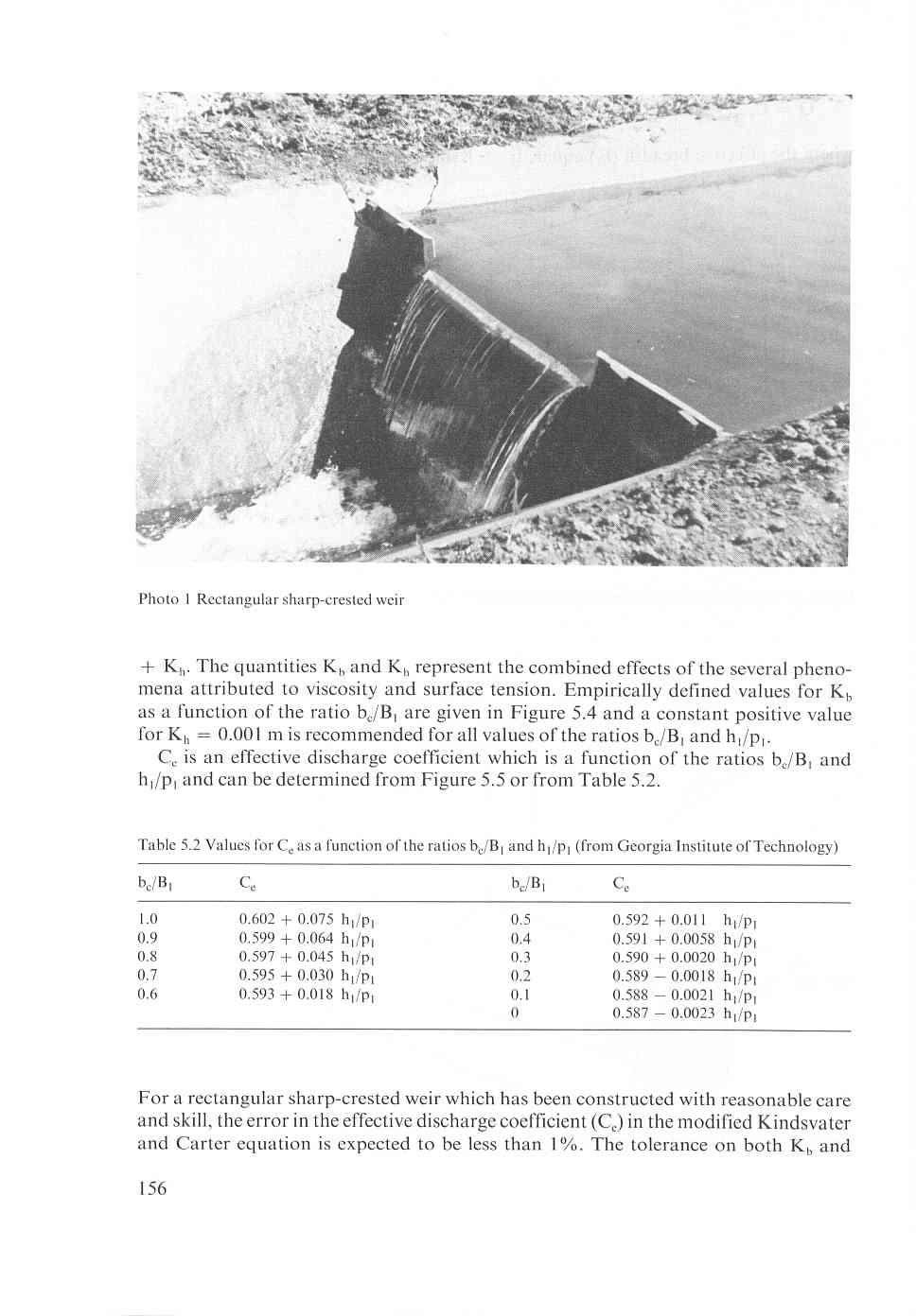
1 5 Sharp-crested weirs Classified under the term sharp-crested or thin-plate weirs are those overflow structures whose length of crest in the direction of flow is equal to or less than two millimetres. The weir plate should be smooth and plane, especially on the upstream face, while the crest surface and the sides of the notch should have plane surfaces which make sharp 90-degree intersections with the upstream weir face. The downstream edge of the notch should be bevelled if the weir plate is thicker than two millimetres. The bevelled surfaces should make an angle of not less than 45-degrees with the surface of a rectangular notch and an angle of not less than 60 degrees if the throat section is non-rectangular (see Figure 5. I). FLOW - FLOW min rectangular notch, trapezoidal and circular weirs Figure 5.1 Flow-wise cross-section over a sharp-crested (thin-plate) weir V-notch and sutm weirs In general sharp-crested weirs will be used where highly accurate discharge measurements are required, for example in hydraulic laboratories and industry. To obtain this high accuracy, provision should be made for ventilating the nappe to ensure that the pressure on the sides and surfaces of the nappe is atmospheric (see Section 1.14). The downstream water level should be low enough to ensure that it does not interfere with the ventilation of the air pocket beneath the nappe. Consequently, the required loss of head for modular flow will always exceed the upstream head over the weir crest (h,) by about 0.05 m, which is one of the major disadvantages of a sharp-crested weir. 5.1 Rectangular sharp-crested weirs Description A rectangular notch, symmetrically located in a vertical thin (metal) plate which is 153
2 placed perpendicular to the sides and bottom of a straight channel, is defined as a rectangular sharp-crested weir. Rectangular sharp-crested weirs comprise the following three types: a. Fully contracted weirs, i.e. a weir which has an approach channel whose bed and walls are sufficiently remote from the weir crest and sides for the channel boundaries to have no significant influence on the contraction of the nappe. b. Full width weirs, i.e. a weir which extends across the full width of the rectangular approach channel (B,/b, = 1.0). In literature this weir is frequently referred to as a rectangular suppressed weir or Rehbock weir. c. Partially contracted weir, i.e. a weir the contractions of which are not fully developed due to the proximity of the walls and/or the bottom of the approach channel. In general, all three types of rectangular weirs should be located in a rectangular approach channel (See Figure 5.2 and 5.3). If, however, the approach channel is sufficiently large {B,(h, + p,) 2 lob,h,} to render the velocity of approach negligible, and the weir is fully contracted, the shape of the approach channel is unimportant. Consequently, the fully contracted weir may be used with non-rectangular approach channels. The sides of the rectangular channel above the level of the crest of a full-width weir should extend at least 0.3 hlmax downstream of the weir crest. The fully contracted weir may be described by the limitations on BI-b,, b,/b,, h,/p,, h,/b,, h,, b,, andp, asshownintable5.1. Table 5.1 Limitations of a rectangular sharp-crested fully contracted weir BI-b, > 4h, h,/p, < 0.5 h,/b, < m < h, < 0.60 m b, > p, > 0.30m A comparison of these limitations with those given in Section 5. I.3 shows that the fully contracted weir has limitations that are both more numerous and more stringent than the partially contracted weir and full width weir Evaluation of discharge As mentioned in Section , the basic head-discharge equation for a rectangular sharp-crested weir is 2 Q = CC3J2g b, hl. (5-1) To apply this equation to fully contracted, full-width, and partially contracted thinplate weirs, it is modified as proposed by Kindsvater and Carter (1957), 154
3 2 Q = Ce 3 fi be he'.5 (5-2) where the effective breadth (be) equals b, + Kb and the effective head (he) equals h, Figure 5.2 The rectangular sharp-crested weir (thin-plate weir) 1 to2 Figure 5.3 Enlarged view ofcrest and side of rectangular sharp-crested weir 155
4
5 K, is expected to be of the order of k m. The method by which these errors are to be combined with other sources of error is shown in Annex Limits of application a. The practical lower limit of h, is related to the magnitude of the influence value of K, in metres O o 1.2 ratio b,/b1 Figure 5.4 Values of K, as a function of b,/b, (derived from tests at the logy by Kindsvater and Carter 1957) Georgia Institute of Techno- value of Ca O value of hl/pl Figure 5.5 Ce as a function of the ratios bjb, and h,/p, (after Georgia Institute of Technology) 157
6 of fluid properties and the accuracy with which h, can be determined. The recommended lower limit is 0.03 m; b. Böss (1929) has shown that critical depth will occur in the approach channel upstream from a weir if the ratio h,/p, exceeds about 5. Thus, for values of h,/p, greater than 5 the weir is not a control section as specified in Section Further limitations on hl/pl arise from observational difficulties and measurement errors. For precise discharge measurements the recommended upper limit for h,/p, equals 2.0, while p, should be at least 0.10 m; c. The breadth (bj of the weir crest should not be less than O. 15 m; d. To facilitate aeration of the nappe the tailwater level should remain at least 0.05 m below crest level. 5.2 V-notch sharp-crested weirs Description A V-shaped notch in a vertical thin plate which is placed perpendicular to the sides and bottom of a straight channel is defined as a V-notch sharp-crested weir. The line which bisects the angle of the notch should be vertical and at the same distance from both sides of the channel (see Section 5). The V-notch sharp-crested weir is one of the most precise discharge measuring devices suitable for a wide range of flow. In international literature, the V-notch sharp-crested-weir is frequently referred to as the Thomson weir. The weir is shown diagrammatically in Figures 5.6 and 5.1. The following flow regimes are encountered with V-notch sharp-crested or thin-plate weirs: a. Partially contracted weir, i.e. a weir the contractions of which along the sides of the V-notch are not fully developed due to the proximity of the walls and/or bed of the approach channel. b. Fully contracted weir, i.e. a weir which has an approach channel whose bed and sides are sufficiently remote from the edges of the V-notch to allow for a sufficiently great approach velocity component parallel to the weir face so that the contraction is fully developed. These two types of V-notch sharp-crested weirs may be classified by the following limitations on h,/p,, h,/b,, hl, pi and BI. It should be noted that in this classification fully contracted flow is a subdivision of partially contracted flow. Table 5.3 Classification and limits of application of V-notch sharp-crested (thin-plate) weirs (after IS0 1971, France) Partially contracted weir Fully contracted weir hi/pi c 1.2 h,/p, f 0.4 h,/b, f 0.4 h,/b, C m < hl < 0.6m 0.05 m < h, f 0.38 m PI > 0.1 m p1 > 0.45m BI > 0.6m BI > 0.90m 158
7 I Figure 5.6 V-notch sharp-crested weir 159
8 From this table it appears that from a hydraulica1 point of view a weir may be fully contracted at low heads while at increasing h, it becomes partially contracted. The partially contracted weir should be located in a rectangular approach canal. Owing to a lack of experimental data relating to the discharge coefficient over a sufficiently wide range of the ratios hl/pl and p,/b,, only the 90-degree V-notch should be used as a partially contracted V-notch weir. The fully contracted weir may be placed in a non-rectangular approach channel provided that the cross-sectional area of the selected approach channel is not less than that of the rectangular channel as prescribed in Table Evaluation of discharge As shown in Section I. 13.3, the basic head-discharge equation for a V-notch sharpcrested weir is 8 e Q = Ce-& tanz h, (5-3) To apply this equation to both fully and partially contracted sharp-crested weirs, it is modified to a form proposed by Kindsvater and Carter (1957) 8 e Q = Cen& tan2 hez.5 (5-4) where 8 equals the angle induced between the sides of the notch and heis the effective head which equals h, + Kh. The quantity Kh represents the combined effects of fluid properties. Empirically defined values for Kh as a function of the notch angle (O) are shown in Figure 5.8. For water at ordinary temperature, i.e. 5 C to 30 C (or 40 F to 85 F) the effective coefficient of discharge (Ce) for a V-notch sharp-crested weir is a function of three variables value of Kh in millimetres Figure 5.8 Value of Kh as a function of the notch angle 160 value of notch angle 0 in degrees
9 value of Ce O O0 120 value of notch angle 0 in degrees Figure 5.9 Coefficient ofdischarge Ce as a function of notch angle for fully contracted V-notch weirs (5-5) If the ratios h,/p, < 0.4 and h,/b, < 0.2, the V-notch weir is fully contracted and Ce becomes a function of only the notch angle 0, as illustrated in Figure 5.9. If on the other hand the contraction of the nappe is not fully developed, the effective discharge coefficient (Ce) can be read from Figure 5.10 for a 90-degree V-notch only. Insufficient experimental data are available to produce Ce-values for non-90-degree partially contracted V-notch weirs. The coefficients given in Figures 5.9 and 5.10 for a V-notch sharp-crested weir can be expected to have an accuracy of the order of 1.O% and of 1.O% to 2.0% respectively, provided that the notch is constructed and installed with reasonable care and skill in accordance with the requirements of Sections 5 and The tolerance on Kh is expected to be of the order of m. The method by which these errors are to be combined with other sources of error is shown in Annex 2. effective discharge coefficient Ce /PI Ce Figure 5.10 Ce as a function of hl/pl and pl/b, for 90-degree V-notch sharp-crested weir. (From British Standard 3680: Part 4A and ISO/TC 113/GT 2 (France-IO) 1971) 161
10 ~ ~ ~ ~ Table 5.4 Discharges for V-notch sharp-crested weirs for heads in metres (adapted from ISO/TC 113/GT 2 (France- IO) 1971) Head Discharge ]/sec Head Discharge I/sec Head Discharge I/sec Head Discharge I/scc metre 90" '/L900 '/,9O0 metre 90" '/,90 '/,90" metre 90" '/* 90" 90" o. I02 O. 103 O. I O. I I I : ' I L I I I O I O
11 Head Discharge I/sec Head Discharge I/sec Head Discharge I/sec metre 90" '/,90 'I490 metre 90" L/2900 'I490" metre 90" 'I2 90" '/4 90" I.O I I I.863 I I I , O Note: The number of significant figures given for the discharge does not imply a corresponding accuracy in the knowledge of the value given. r I TQl-7 1, 90 degree v-mtch # 93 degree Y-mtch a 90 degree V-mtch 163
12 5.2.3 Limits of application The limits of application of the Kindsvater and Carter equation for V-notch sharpcrested weirs are: a. The ratio h,/p, should be equal to or less than 1.2; b. The ratio h,/b, should be equal to or less than 0.4; c. The head over the vertex of the notch h, should not be less than 0.05 m nor more than 0.60 m; d. The height of the vertex of the notch above the bed of the approach channel (p,) should not be less than O. 10 m; e. The width of the rectangular approach channel should exceed 0.60 m; f. The notch angle of a fully contracted weir may range between 25 and 100 degrees. Partially contracted weirs have a 90-degree notch only; g. The tailwater level should remain below the vertex of the notch Rating tables Commonly used sizes of V-notches for fully contracted thin-plate weirs are the 90-degree, 90-degree and 90-degree notches in which the dimensions across the top are twice, equal to and half the vertical depth respectively. The related ratings are given in Table Cipoletti weir Description A Cipoletti weir is a modification of a fully contracted rectangular sharp-crested weir and has a trapezoïdal control section, the crest being horizontal and the sides sloping outward with an inclination of 1 horizontal to 4 vertical (Figure 5.1 I). Cipoletti (1886) assumed that, due to the increase of side-contraction with an increasing head, the decrease of discharge over a fully contracted rectangular sharp-crested weir with breadth b, would be compensated by the increase of discharge due to the inclination of the sides of the control-section. This compensation thus allows the head-discharge equation of a full width rectangular weir to be used. It should be noted, however, 2 to 3 h, max n Figure S. 1 I Definition sketch of a Cipoletti weir 164 upstream view ---approach channel
Open Channel Hydraulics III - Sharpcrested
 PDHonline Course H140 (2 PDH) Open Channel Hydraulics III - Sharpcrested Weirs Instructor: Harlan H. Bengtson, Ph.D., PE 2012 PDH Online PDH Center 5272 Meadow Estates Drive Fairfax, VA 22030-6658 Phone
The method by which this error has to be combined with other sources of error is I
 The error in the discharge coefficient (including C,) of a triangular broad-crested (truncated) eir, hich has been constructed ith reasonable care and skill, may be deduced form the equation X, = f (3
Experimental Investigation on the Influence of Density of Fluid. On Efficiency of V- Notch
 International Journal of Advances in Scientific Research and Engineering (ijasre) E-ISSN : 2454-8006 DOI: http://dx.doi.org/10.7324/ijasre.2017.32515 Vol.3 (9) Oct - 2017 Experimental Investigation on
Open Channel Flow Measurement Weirs and Flumes
 Open Channel Flow Measurement Weirs and Flumes by Harlan H. Bengtson, PhD, P.E. 1. Introduction Measuring the flow rate of water in an open channel typically involves some type of obstruction in the path
New method for discharge hydrograph measurement of the free overflow with full-width, thin-plate weir
 New method for discharge hydrograph measurement of the free overflow with full-width, thin-plate weir Lajos Hovany* University of Novi Sad, Faculty of Civil Engineering Subotica, Kozaračka, a, 4000, Subotica,
EFFECT OF VERTICAL CURVATURE OF FLOW AT WEIR CREST ON DISCHARGE COEFFICIENT
 Ninth International Water Technology Conference, IWTC9 2005, Sharm El-Sheikh, Egypt 249 EFFECT OF VERTICAL CURVATURE OF FLOW AT WEIR CREST ON DISCHARGE COEFFICIENT Kassem Salah El-Alfy Associate Prof.,
R09. d water surface. Prove that the depth of pressure is equal to p +.
 Code No:A109210105 R09 SET-1 B.Tech II Year - I Semester Examinations, December 2011 FLUID MECHANICS (CIVIL ENGINEERING) Time: 3 hours Max. Marks: 75 Answer any five questions All questions carry equal
Flow Characteristics and Modelling of Head-discharge Relationships for Weirs
 Chapter 8 Flow Characteristics and Modelling of Head-discharge Relationships for Weirs 8.1 Introduction In Chapters 5 and 7, the formulations of the numerical models for the simulations of flow surface
Head Discharge Relationship of Thin Plated Rectangular Lab Fabricated Sharp Crested Weirs
 Journal of Applied Fluid Mechanics, Vol. 9, No. 3, pp. 1231-1235, 2016. Available online at www.jafmonline.net, ISSN 1735-3572, EISSN 1735-3645. DOI: 10.18869/acadpub.jafm.68.228.23128 Head Discharge Relationship
Discharge measurements
 Discharge measurements DISCHARGE MEASUREMENTS Suitability of methods and equipment for measurements where, under what conditions and for what reason discharge is measured determination of discharge in
Laboratory experiences on open channel flow (in collaboration with Dr. Ing. Luca Milanesi)
") Classwork 8 Laboratory experiences on open channel flow (in collaboration with Dr. Ing. Luca Milanesi) Why a practical lesson on open channel flow? In the first part of the course we studied open channel
Classwork 8 Laboratory experiences on open channel flow (in collaboration with Dr. Ing. Luca Milanesi) Why a practical lesson on open channel flow? In the first part of the course we studied open channel
y 2 = 1 + y 1 This is known as the broad-crested weir which is characterized by:
 CEE 10 Open Channel Flow, Dec. 1, 010 18 8.16 Review Flow through a contraction Critical and choked flows The hydraulic jump conservation of linear momentum y = 1 + y 1 1 + 8Fr 1 8.17 Rapidly Varied Flows
Stage Discharge Tabulation for Only Orifice Flow
 Stage Discharge Tabulation for Only Orifice Flow DEPTH STAGE DISCHARGE (meters) (feet) (meters) (feet) (m 3 /s) (ft 3 /s) 0 0.20 0.40 0.60 0.80 1.00 1.20 1.40 1.60 1.80 2.00 0.7 1.3 2.0 2.6 3.3 3.9 4.6
SOE2156: Fluids Lecture 7
 Weirs and SOE2156: Fluids Lecture 7 Vee Vee Last lecture { assumed the channel was uniform (constant depth, shape, slope etc.) { steady uniform Found that : location of free surface to be determined 2
Laboratory exercise 1: Open channel flow measurement
 Chapter 1 Laboratory exercise 1: Open channel flow measurement Laboratory exercise Open channel flow measurement is placed on the Faculty of Civil and Geodetic Engineering, on Department of Environmental
NPTEL Quiz Hydraulics
 Introduction NPTEL Quiz Hydraulics 1. An ideal fluid is a. One which obeys Newton s law of viscosity b. Frictionless and incompressible c. Very viscous d. Frictionless and compressible 2. The unit of kinematic
Comparative Analysis of a Parabolic Weir
 Comparative Analysis of a Parabolic Weir Prajakta N. Badhe 1, Mohd. Zain Kangda 2, Shobha G. Kundu 3, Abdul Ashfak Khan 4 Asst. Professor, Department of Civil Engineering, PCE, Maharashtra, India 1 Asst.
Study of Flow Characteristics of Contracted Sharp Crested Rectangular Weir Rahul Pandey 1, Dr.S.K.Mittal 2 and Prof. M.K.
 Study of Flow Characteristics of Contracted Sharp Crested Rectangular Weir Rahul Pandey 1, Dr.S.K.Mittal 2 and Prof. M.K.Choudhary 3 1 M.Tech Student, Department of Civil Engineering, MANIT Bhopal (M.P.),
CE 6403 APPLIED HYDRAULIC ENGINEERING UNIT - II GRADUALLY VARIED FLOW
 CE 6403 APPLIED HYDRAULIC ENGINEERING UNIT - II GRADUALLY VARIED FLOW Dynamic equations of gradually varied and spatially varied flows - Water surface flow profile classifications: Hydraulic Slope, Hydraulic
Discharge Measurements in Open Channels using Compound Sharp-Crested Weirs
 I'NCINEER - Vol. XXXX, No. 03, pp. 31-38,2007 O Tlie Institution of Engineers, Sri Lanka Discharge Measurements in Open Channels using Compound Sharp-Crested Weirs M. Piratheepan, N.E.F. Winston and K.P.P.
Presented by: Civil Engineering Academy
 Presented by: Civil Engineering Academy Open-Channel Flow Uniform Flow (See CERM Ch. 19) Characterized by constant depth volume, and cross section. It can be steady or unsteady Non-uniform Flow *Not on
Cavitation occurs whenever the pressure in the flow of water drops to the value of the pressure of the saturated water vapour, pv (at the prevailing
 Cavitation occurs whenever the pressure in the flow of water drops to the value of the pressure of the saturated water vapour, pv (at the prevailing temperature); cavities filled by vapour, and partly
Discharge Coefficients of Oblique Weirs
 Utah State University DigitalCommons@USU All Graduate Theses and Dissertations Graduate Studies 8-011 Discharge Coefficients of Oblique Weirs Samuel Egnew Tingey Utah State University Follow this and additional
UNIT I FLUID PROPERTIES AND STATICS
 SIDDHARTH GROUP OF INSTITUTIONS :: PUTTUR Siddharth Nagar, Narayanavanam Road 517583 QUESTION BANK (DESCRIPTIVE) Subject with Code : Fluid Mechanics (16CE106) Year & Sem: II-B.Tech & I-Sem Course & Branch:
Annex 3 Side weirs and oblique weirs
 Annex 3 Side weirs and oblique weirs 3.1 ntroduction Most of the weirs described in this book serve mainly to measure discharges. Some, however, such as those described in Chapters 4 and 6 can also be
International Journal of Advance Research, IJOAR.org ISSN
 International Journal of Advance Research, IJOAR.org 1 International Journal of Advance Research, IJOAR.org Volume 1, Issue 9, September 2013, Online: Coefficient Of Discharge For A Compound Weir Combined
Flow Characteristics of Sharp Crested Rectangular Weir: A Review
 IJISET - International Journal of Innovative Science, Engineering & Technology, Vol. Issue, March 016. Flow Characteristics of Sharp Crested Rectangular Weir: A Review 1 Rahul PandeyP P, Dr.S.K.MittalP
6.4 Head-Discharge Equations Based on Experimentation
 ~ contracted, we have found that L = 0.25bC does not produce an accurate rating, but an accurate rating is obtained with L = 2b,. At the present time the WinFlume computer program will warn the designer
conservation of linear momentum 1+8Fr = 1+ Sufficiently short that energy loss due to channel friction is negligible h L = 0 Bernoulli s equation.
 174 Review Flow through a contraction Critical and choked flows The hydraulic jump conservation of linear momentum y y 1 = 1+ 1+8Fr 1 8.1 Rapidly Varied Flows Weirs 8.1.1 Broad-Crested Weir Consider the
Discharge measurement structures
 Discharge measurement structures Discharge measurement structures Third revised edition Edited by M.G. Bos Publication 20 International Institute for Land Reclamation and Improvement/ILRI P.O.BOX 45,6700
If a stream of uniform velocity flows into a blunt body, the stream lines take a pattern similar to this: Streamlines around a blunt body
 Venturimeter & Orificemeter ELEMENTARY HYDRAULICS National Certificate in Technology (Civil Engineering) Chapter 5 Applications of the Bernoulli Equation The Bernoulli equation can be applied to a great
Hydromechanics: Course Summary
 Hydromechanics: Course Summary Hydromechanics VVR090 Material Included; French: Chapters to 9 and 4 + Sample problems Vennard & Street: Chapters 8 + 3, and (part of it) Roberson & Crowe: Chapter Collection
Fluid Mechanics Prof. S.K. Som Department of Mechanical Engineering Indian Institute of Technology, Kharagpur
 Fluid Mechanics Prof. S.K. Som Department of Mechanical Engineering Indian Institute of Technology, Kharagpur Lecture - 42 Flows with a Free Surface Part II Good morning. I welcome you to this session
Closed duct flows are full of fluid, have no free surface within, and are driven by a pressure gradient along the duct axis.
 OPEN CHANNEL FLOW Open channel flow is a flow of liquid, basically water in a conduit with a free surface. The open channel flows are driven by gravity alone, and the pressure gradient at the atmospheric
FLOW MODELLING OF INCLINED TRAPEZOIDAL WEIR WITH A NEW APPROACH
 International Journal of Science, Environment and Technology, Vol. 7, No 3, 018, 83 834 ISSN 78-3687 (O) 77-663X (P) FLOW MODELLING OF INCLINED TRAPEZOIDAL WEIR WITH A NEW APPROACH 1 M.N. Shesha Prakash,
MAHATMA GANDHI MISSION S JAWAHARLAL NEHRU ENGINEERING COLLEGE, AURANGABAD. (M.S.)
") MAHATMA GANDHI MISSION S JAWAHARLAL NEHRU ENGINEERING COLLEGE, AURANGABAD. (M.S.) DEPARTMENT OF CIVIL ENGINEERING FLUID MECHANICS I LAB MANUAL Prepared By Prof. L. K. Kokate Lab Incharge Approved By Dr.
MAHATMA GANDHI MISSION S JAWAHARLAL NEHRU ENGINEERING COLLEGE, AURANGABAD. (M.S.) DEPARTMENT OF CIVIL ENGINEERING FLUID MECHANICS I LAB MANUAL Prepared By Prof. L. K. Kokate Lab Incharge Approved By Dr.
15. GRIT CHAMBER 15.1 Horizontal Velocity in Flow Though Grit Chamber
 15. GRIT CHAMBER Grit chamber is the second unit operation used in primary treatment of wastewater and it is intended to remove suspended inorganic particles such as sandy and gritty matter from the wastewater.
Chapter 4: Non uniform flow in open channels
 Chapter 4: Non uniform flow in open channels Learning outcomes By the end of this lesson, students should be able to: Relate the concept of specific energy and momentum equations in the effect of change
New Website: Mr. Peterson s Address:
 Brad Peterson, P.E. New Website: http://njut2009fall.weebly.com Mr. Peterson s Email Address: bradpeterson@engineer.com Lesson 1, Properties of Fluids, 2009 Sept 04, Rev Sept 18 Lesson 2, Fluid Statics,
CHAPTER FOUR Flow Measurement and Control
 CHAPTER FOUR Flow Measurement and Control 4.1 INTRODUCTION Proper treatment plant operation requires knowledge of the rate at which flow enters the plant and controlling the flow between unit processes.
UNIT IV. Flow through Orifice and Mouthpieces and Flow through Notchs and Weirs
 SIDDHARTH GROUP OF INSTITUTIONS :: PUTTUR Siddharth Nagar, Narayanavanam Road 517583 QUESTION BANK (DESCRIPTIVE) Subject with Code : FM(15A01305) Year & Sem: II-B.Tech & I-Sem Course & Branch: B.Tech -
DEPARTMENT OF CIVIL AND ENVIRONMENTAL ENGINEERING Urban Drainage: Hydraulics. Solutions to problem sheet 2: Flows in open channels
 DEPRTMENT OF CIVIL ND ENVIRONMENTL ENGINEERING Urban Drainage: Hydraulics Solutions to problem sheet 2: Flows in open channels 1. rectangular channel of 1 m width carries water at a rate 0.1 m 3 /s. Plot
10.52 Mechanics of Fluids Spring 2006 Problem Set 3
 10.52 Mechanics of Fluids Spring 2006 Problem Set 3 Problem 1 Mass transfer studies involving the transport of a solute from a gas to a liquid often involve the use of a laminar jet of liquid. The situation
Module 15 : Grit Chamber. Lecture 19 : Grit Chamber
 1 P age Module 15 : Grit Chamber Lecture 19 : Grit Chamber 2 P age Grit chamber is the second unit operation used in primary treatment of wastewater and it is intended to remove suspended inorganic particles
Chapter 3.8: Energy Dissipators. By Dr. Nuray Denli Tokyay
 Chapter 3.8: Energy Dissipators By Dr. Nuray Denli Tokyay 3.1 Introduction A stilling basin is a short length of paved channel placed at the foot of a spillway or any other source of supercritical flow
Hydraulics Part: Open Channel Flow
 Hydraulics Part: Open Channel Flow Tutorial solutions -by Dr. K.N. Dulal Uniform flow 1. Show that discharge through a channel with steady flow is given by where A 1 and A 2 are the sectional areas of
1.060 Engineering Mechanics II Spring Problem Set 8
 1.060 Engineering Mechanics II Spring 2006 Due on Monday, May 1st Problem Set 8 Important note: Please start a new sheet of paper for each problem in the problem set. Write the names of the group members
Experiment- To determine the coefficient of impact for vanes. Experiment To determine the coefficient of discharge of an orifice meter.
 SUBJECT: FLUID MECHANICS VIVA QUESTIONS (M.E 4 th SEM) Experiment- To determine the coefficient of impact for vanes. Q1. Explain impulse momentum principal. Ans1. Momentum equation is based on Newton s
MAHATMA GANDHI MISSION S JAWAHARLAL NEHRU ENGINEERING COLLEGE, FLUID MECHANICS LABORATORY MANUAL
 MAHATMA GANDHI MISSION S JAWAHARLAL NEHRU ENGINEERING COLLEGE, AURANGABAD. (M.S.) DEPARTMENT OF CIVIL ENGINEERING FLUID MECHANICS LABORATORY MANUAL Prepared By Mr. L. K. Kokate Lab Incharge Approved By
Long-Throated Flumes. 6. Hydraulic Theory and Computations for. 6.1 Continuity Equation
 6. Hydraulic Theory and Computations for Long-Throated Flumes The purpose of this chapter is to explain the fimdamental principles involved in analytically modeling the flow through weirs and flumes, so
Chapter 3 Bernoulli Equation
 1 Bernoulli Equation 3.1 Flow Patterns: Streamlines, Pathlines, Streaklines 1) A streamline, is a line that is everywhere tangent to the velocity vector at a given instant. Examples of streamlines around
Free Flow Below Skew Sluice Gate
 International Journal of Engineering Research and Development e-issn: 2278-67X, p-issn: 2278-8X, www.ijerd.com Volume, Issue 3 (March 24), PP.44-52 Talib Mansoor Civil Engineering Department, Aligarh Muslim
Guo, James C.Y. (1999). "Critical Flow Section in a Collector Channel," ASCE J. of Hydraulic Engineering, Vol 125, No. 4, April.
. Critical Flow Section in a Collector Channel, ASCE J. of Hydraulic Engineering, Vol 125, No. 4, April.") Guo, James C.Y. (1999). "Critical Flow Section in a Collector Channel," ASCE J. of Hydraulic Engineering, Vol 15, No. 4, April. CRITICAL FLOW SECTION IN A COLLECTOR CHANNEL By James C.Y. Guo, PhD, P.E.
Guo, James C.Y. (1999). "Critical Flow Section in a Collector Channel," ASCE J. of Hydraulic Engineering, Vol 15, No. 4, April. CRITICAL FLOW SECTION IN A COLLECTOR CHANNEL By James C.Y. Guo, PhD, P.E.
Created by Simpo PDF Creator Pro (unregistered version)
") 2 nd Semester TRANSITIONS STRUCTURES 1 of 9 A transition is a local change in cross-section which produces a variation of flow from one uniform state to another due to the change in cross sections of channels.
2 nd Semester TRANSITIONS STRUCTURES 1 of 9 A transition is a local change in cross-section which produces a variation of flow from one uniform state to another due to the change in cross sections of channels.
BRCM COLLEGE OF ENGINEERING & TECHNOLOGY Practical Experiment Instructions Sheet
 Exp. Title FLUID MECHANICS- I LAB Syllabus FM-I Semester-4 th Page No. 1 of 1 Internal Marks: 25 L T P External Marks: 25 0 0 2 Total Marks: 50 1. To determine the met centric height of a floating body
53:071 Principles of Hydraulics Laboratory Experiment #3 ANALYSIS OF OPEN-CHANNEL FLOW TRANSITIONS USING THE SPECIFIC ENERGY DIAGRAM
 53:071 Principles of Hydraulics Laboratory Experiment #3 ANALYSIS OF OPEN-CHANNEL FLOW TRANSITIONS USING THE SPECIFIC ENERGY DIAGRAM Principle Adaptation of the Bernoulli equation to open-channel flows
presented by Umut Türker Open Channel Flow
 presented by Umut Türker Open Channel Flow What is open channel flow? Open channel flow is a flow which has a free surface and flows due to the gravitational effect What is open channel flow? Open channel
INSTITUTE OF AERONAUTICAL ENGINEERING Dundigal, Hyderabad AERONAUTICAL ENGINEERING QUESTION BANK : AERONAUTICAL ENGINEERING.
 Course Name Course Code Class Branch INSTITUTE OF AERONAUTICAL ENGINEERING Dundigal, Hyderabad - 00 0 AERONAUTICAL ENGINEERING : Mechanics of Fluids : A00 : II-I- B. Tech Year : 0 0 Course Coordinator
Dr. Muhammad Ali Shamim ; Internal 652
 Dr. Muhammad Ali Shamim ali.shamim@uettaxila.edu.pk 051-904765; Internal 65 Channel Tranistions A channel transition is defined as change in channel cross section e.g. change in channel width and/or channel
Closed duct flows are full of fluid, have no free surface within, and are driven by a pressure gradient along the duct axis.
 OPEN CHANNEL FLOW Open channel flow is a flow of liquid, basically water in a conduit with a free surface. The open channel flows are driven by gravity alone, and the pressure gradient at the atmospheric
CEE 3310 Open Channel Flow, Nov. 26,
 CEE 3310 Open Channel Flow, Nov. 6, 018 175 8.10 Review Open Channel Flow Gravity friction balance. y Uniform Flow x = 0 z = S 0L = h f y Rapidly Varied Flow x 1 y Gradually Varied Flow x 1 In general
Lecture23. Flowmeter Design.
 Lecture23 Flowmeter Design. Contents of lecture Design of flowmeter Principles of flow measurement; i) Venturi and ii) Orifice meter and nozzle Relationship between flow rate and pressure drop Relation
COURSE CODE : 3072 COURSE CATEGORY : B PERIODS/ WEEK : 5 PERIODS/ SEMESTER : 75 CREDIT : 5 TIME SCHEDULE
 COURSE TITLE : FLUID MECHANICS COURSE CODE : 307 COURSE CATEGORY : B PERIODS/ WEEK : 5 PERIODS/ SEMESTER : 75 CREDIT : 5 TIME SCHEDULE MODULE TOPIC PERIOD 1 Properties of Fluids 0 Fluid Friction and Flow
A Model Answer for. Problem Set #7
 A Model Answer for Problem Set #7 Pipe Flow and Applications Problem.1 A pipeline 70 m long connects two reservoirs having a difference in water level of 6.0 m. The pipe rises to a height of 3.0 m above
Experimental Investigations of Nappe Profile and Pool Depth for Broad Crested Weirs
 International Journal of Engineering Research and General Science Volume, Issue, January-February, ISSN 9-73 Experimental Investigations of Nappe Profile and Pool Depth for Broad Crested Weirs Mohammed
Chapter 8: Flow in Pipes
 Objectives 1. Have a deeper understanding of laminar and turbulent flow in pipes and the analysis of fully developed flow 2. Calculate the major and minor losses associated with pipe flow in piping networks
5 th INTERNATIONAL CONFERENCE Contemporary achievements in civil engineering 21. April Subotica, SERBIA
 5 th INTERNATIONAL CONFERENCE Contemporary achievements in civil engineering. April 07. Subotica, SERBIA DIFFERENT HEIGHT THIN-PLATE WEIRS FOR MEASURING DISCHARGE HYDROGRAPHS Lajos Hovány UDK: 68. DOI:0.445/konferencijaGFS07.07
Experiment (4): Flow measurement
: Flow measurement") Experiment (4): Flow measurement Introduction: The flow measuring apparatus is used to familiarize the students with typical methods of flow measurement of an incompressible fluid and, at the same time
Experiment (4): Flow measurement Introduction: The flow measuring apparatus is used to familiarize the students with typical methods of flow measurement of an incompressible fluid and, at the same time
Local Scouring due to Flow Jet at Downstream of Rectangular Sharp-Crested Weirs
 Local Scouring due to Flow Jet at Downstream of Rectangular Sharp-Crested Weirs DEHGHANI, AMIR. AHMAD 1, BASHIRI, HAMID and MESHKATI SHAHMIRZADI, MOHAMMAD. EBRAHIM 3 1,3 Dept. of Water Engineering, Gorgan
Visualization of flow pattern over or around immersed objects in open channel flow.
 EXPERIMENT SEVEN: FLOW VISUALIZATION AND ANALYSIS I OBJECTIVE OF THE EXPERIMENT: Visualization of flow pattern over or around immersed objects in open channel flow. II THEORY AND EQUATION: Open channel:
Experiment No.4: Flow through Venturi meter. Background and Theory
 Experiment No.4: Flow through Venturi meter Background and Theory Introduction Flow meters are used in the industry to measure the volumetric flow rate of fluids. Differential pressure type flow meters
Flow over oblique Side Weir
 Damascus University Journal Vol. (8) - No. () 0 Al-Tali Flow over olique Side Weir Eng. Azza N. Al-Tali * Astract In this paper, an olique side weir was studied y nine models installed at the entrance
EFFECT OF BAFFLE BLOCKS ON THE PERFORMANCE OF RADIAL HYDRAULIC JUMP
 Fourth International Water Technology Conference IWTC 99, Alexandria, Egypt 255 EFFECT OF BAFFLE BLOCKS ON THE PERFORMANCE OF RADIAL HYDRAULIC JUMP O. S. Rageh Irrigation & Hydraulics Dept., Faculty of
EXPERIMENTAL STUDY OF BACKWATER RISE DUE TO BRIDGE PIERS AS FLOW OBSTRUCTIONS
 Tenth International Water Technology Conference, IWTC1 6, Alexandria, Egypt 19 EXPERIMENTAL STUDY OF BACKWATER RISE DUE TO BRIDGE PIERS AS FLOW OBSTRUCTIONS Kassem Salah El-Alfy Associate Prof., Irrigation
Rock Sizing for Waterway & Gully Chutes
 Rock Sizing for Waterway & Gully Chutes WATERWAY MANAGEMENT PRACTICES Photo 1 Rock-lined waterway chute Photo 2 Rock-lined gully chute 1. Introduction A waterway chute is a stabilised section of channel
Lecture 13 Flow Measurement in Pipes. I. Introduction
 Lecture 13 Flow Measurement in Pipes I. Introduction There are a wide variety of methods for measuring discharge and velocity in pipes, or closed conduits Many of these methods can provide very accurate
Hydraulic (Piezometric) Grade Lines (HGL) and
 Grade Lines (HGL) and") Hydraulic (Piezometric) Grade Lines (HGL) and Energy Grade Lines (EGL) When the energy equation is written between two points it is expresses as in the form of: Each term has a name and all terms have
Hydraulic (Piezometric) Grade Lines (HGL) and Energy Grade Lines (EGL) When the energy equation is written between two points it is expresses as in the form of: Each term has a name and all terms have
1.060 Engineering Mechanics II Spring Problem Set 4
 1.060 Engineering Mechanics II Spring 2006 Due on Monday, March 20th Problem Set 4 Important note: Please start a new sheet of paper for each problem in the problem set. Write the names of the group members
Flow Measurement in Pipes and Ducts COURSE CONTENT
 Flow Measurement in Pipes and Ducts Dr. Harlan H. Bengtson, P.E. COURSE CONTENT 1. Introduction This course is about measurement of the flow rate of a fluid flowing under pressure in a closed conduit.
Properties and Definitions Useful constants, properties, and conversions
 Properties and Definitions Useful constants, properties, and conversions gc = 32.2 ft/sec 2 [lbm-ft/lbf-sec 2 ] ρwater = 1.96 slugs/ft 3 γwater = 62.4 lb/ft 3 1 ft 3 /sec = 449 gpm 1 mgd = 1.547 ft 3 /sec
28.2 Classification of Jumps
 28.2 Classification of Jumps As mentioned earlier, the supercritical flow Froude number influences the characteristics of the hydraulic jump. Bradley and Peterka, after extensive experimental investigations,
ISO 9906 INTERNATIONAL STANDARD. Rotodynamic pumps Hydraulic performance acceptance tests Grades 1 and 2
 INTERNATIONAL STANDARD ISO 9906 First edition 1999-1-15 Rotodynamic pumps Hydraulic performance acceptance tests Grades 1 and Pompes rotodynamiques Essais de fonctionnement hydraulique pour la réception
Appendix F Channel Grade Control Structures
 Stream Simulation Appendix F Channel Grade Control Structures This appendix briefly describes permanent grade control structures that are sometimes needed in the upstream and/or downstream reaches adjacent
Development of Discharge Prediction Model for Trapezoidal Canals using Simple Portable Flume
 International Journal of Hydraulic Engineering 01, 1(5): 37-4 OI: 10.593/j.ijhe.010105.0 evelopment of ischarge Prediction Model for Trapezoidal Canals using Simple Portable Flume Avinash M. Badar, Aniruddha.
Lab 7: Nonuniform Flow and Open Channel Transitions
 CE 3620: Water Resources Engineering Spring 2015 Lab 7: Nonuniform Flow and Open Channel Transitions BACKGROUND An open channel transition may be defined as a change either in the direction, slope, or
Chapter 8: Flow in Pipes
 8-1 Introduction 8-2 Laminar and Turbulent Flows 8-3 The Entrance Region 8-4 Laminar Flow in Pipes 8-5 Turbulent Flow in Pipes 8-6 Fully Developed Pipe Flow 8-7 Minor Losses 8-8 Piping Networks and Pump
Formation Of Hydraulic Jumps On Corrugated Beds
 International Journal of Civil & Environmental Engineering IJCEE-IJENS Vol:10 No:01 37 Formation Of Hydraulic Jumps On Corrugated Beds Ibrahim H. Elsebaie 1 and Shazy Shabayek Abstract A study of the effect
= 8/15 C1 {2fi Hfr'l (1)
") Pak. J. Agri. SCi. 27 (2) 115, 199 DESIGN OF COMPOUND WEIRS FOR DISCHARGE MEASUREMENTS IN FLUCTUATING STREAMS M. Akhtar Abbas, Allah Bakhsh, M. Asghar Rana & M. Amanat Ali Department of Basic Engineering,
Pak. J. Agri. SCi. 27 (2) 115, 199 DESIGN OF COMPOUND WEIRS FOR DISCHARGE MEASUREMENTS IN FLUCTUATING STREAMS M. Akhtar Abbas, Allah Bakhsh, M. Asghar Rana & M. Amanat Ali Department of Basic Engineering,
V-NOTCH _ V-NOTCH FLOW METERS HYDROLOGICAL INSTRUMENTS
 _ V-NOTCH FLOW METERS HYDROLOGICAL INSTRUMENTS V-NOTCH FLOW METERS Water flow monitoring in open channels is widely employed in environmental and geotechnical field. Leakage measurement is one of the most
FORMATION OF HYDRAULIC JUMPS ON CORRUGATED BEDS
 International Journal of Civil & Environmental Engineering IJCEE-IJENS Vol: 10 No: 01 40 FORMATION OF HYDRAULIC JUMPS ON CORRUGATED BEDS Ibrahim H. Elsebaie 1 and Shazy Shabayek Abstract A study of the
Inclined Rectangular Weir-Flow Modeling
 Earth Science India, eissn: 0974 850 Vol. 4(II), April, 011, pp. 57-67 Inclined Rectangular Weir-Flow Modeling M.N. Shesha Prakash 1, M. B. Ananthayya and Gicy M. Kovoor 1 Vidya Vikas Institute of Engineering
Gradually Varied Flow I+II. Hydromechanics VVR090
 Gradually Varied Flow I+II Hydromechanics VVR090 Gradually Varied Flow Depth of flow varies with longitudinal distance. Occurs upstream and downstream control sections. Governing equation: dy dx So Sf
Investigation of Flow Profile in Open Channels using CFD
 Investigation of Flow Profile in Open Channels using CFD B. K. Gandhi 1, H.K. Verma 2 and Boby Abraham 3 Abstract Accuracy of the efficiency measurement of a hydro-electric generating unit depends on the
Open Channel Flow I - The Manning Equation and Uniform Flow COURSE CONTENT
 Open Channel Flow I - The Manning Equation and Uniform Flow Harlan H. Bengtson, PhD, P.E. COURSE CONTENT 1. Introduction Flow of a liquid may take place either as open channel flow or pressure flow. Pressure
31. Hydraulic Jumps in Sloping Channels
 3. Hydraulic Jumps in Sloping Channels Hydraulic jumps can occur in channels with larger bed slope that the gravitational forces acting on the flow must be included. The major problem in obtanining a useful
Lecture 10: River Channels
 GEOG415 Lecture 10: River Channels 10-1 Importance of channel characteristics Prediction of flow was the sole purpose of hydrology, and still is a very important aspect of hydrology. - Water balance gives
HVAC Clinic. Duct Design
 HVAC Clinic Duct Design Table Of Contents Introduction... 3 Fundamentals Of Duct Design... 3 Pressure Changes In A System... 8 Example 1... 13 Duct Design Methods... 15 Example 2... 15 Introduction The
CE Final Exam. December 12, Name. Student I.D.
 CE 100 - December 12, 2009 Name Student I.D. This exam is closed book. You are allowed three sheets of paper (8.5 x 11, both sides) of your own notes. You will be given three hours to complete four problems.
Lateral Inflow into High-Velocity Channels
 Lateral Inflow into High-Velocity Channels by Richard L. Stockstill PURPOSE: This Coastal and Hydraulics Engineering Technical Note (CHETN) investigates lateral flow discharging into a high-velocity channel.
Real scale investigation of interaction between a supercritical flow and a bottom sill. 1: physical aspects and time-averaged pressures on sill
 Real scale investigation of interaction between a supercritical flow and a bottom sill. 1: physical aspects and time-averaged pressures on sill D. Borsani, E. Larcan, S. Mambretti & E. Orsi Dipartimento