Home Weather Station (HWS) Instruction Manual Table of Contents
|
|
|
- Vernon Terry
- 5 years ago
- Views:
Transcription
1
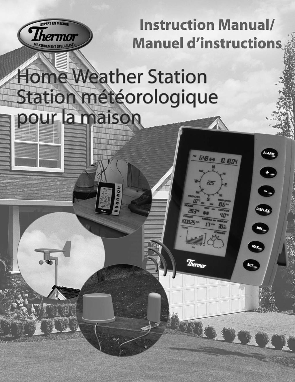
2 Home Weather Station (HWS) Instruction Manual Table of Contents 1. Introduction 2. Safety Notes 3. Weather Station Function and Features Features of the Home Monitor Features of the Thermometer-Transmitter Sensor Features of the Wind Sensor Features of the Rain Sensor 4. Components of your Home Weather Station 5. Setting up the Weather Station A. Mounting B. Powering up your HWS (for the first time) C. Changing the transmitter batteries D. Connecting the Sensors 6. Wireless Transmission 7. LCD Overview 8. LCD Breakdown 9. Optimum Viewing Angle 10. Button Breakdown 11. Setting the Home Monitor Time Date Wind Speed Temperature Pressure Rainfall 12. Setting the Alarm Alarm Clock Indoor Temperature Alarm Outdoor Temperature Alarm 13. Turning off the Alarm(s) 14. Minimum or Maximum Memory Recall 15. Minimum or Maximum Memory Reset 16. Rainfall Measurement Reset 17. Rain Gauge Maintenance 18. Trend Chart 19. Weather Forecasting 20. Barometric Pressure Elevation of Major Cities in Canada Elevation of Major Cities in the US 21. Barometric Pressure Conversions 22. Troubleshooting 23. Product Specifications 24. Warranty 25. Resources to Look At 26. FCC Information
3 This instruction manual is part of this product and should be kept in a safe place for future reference. It contains important information on setup and operation. 1. INTRODUCTION Thank you for purchasing Thermor s Wireless Home Weather Station (HWS). Developed with state of the art technology and digital electronics, this device provides instant readouts of the weather conditions around you. To understand how to properly install and program your weather station, please read this instruction manual carefully and keep it in a safe place. The Home Weather Station and its accuracy is meant for personal use. This information should not be used for scientific purposes. 2. SAFETY NOTES Damage caused by failure to comply with this instruction manual will invalidate any warranty! The manufacturer and supplier will not be held liable for any damages due to failure to comply with this product! In case of harm or damage to a person or property caused by improper handling or failure to comply with this instruction manual, the manufacturer and supplier cannot be held liable. For reason of safety and operation, alteration to this device is strictly prohibited. To operate the weather station, use only supplied adapter and batteries of the recommended type. Do not leave discharged batteries in the device as these may corrode and release chemicals that may damage the unit. Inserting batteries in an incorrect polarity will cause damage to this product. Do not dispose of new or used batteries in a fire as the may explode or release dangerous chemicals into the environment. This product is not a toy; keep out of the reach of children. This product is not to be used for medical purposes or for public information. Any modification or alteration to this product is strictly prohibited without the manufacturer s authorization and may prohibit the user s further use to this product. 3. WEATHER STATION FUNCTION AND FEATURES The home monitor measures the indoor environment of its surrounding area (temperature, humidity and atmospheric pressure) and receives weather data from the following three outdoor sensors: 1) Thermometer-Transmitter Sensor 2) Wind Sensor (speed and direction) 3) Rain Gauge Sensor (cumulative rainfall) The data from the outdoor sensors is transmitted every 128 seconds to bring you the latest weather information which is displayed on the home monitor s LCD (updating the information faster is prohibited by FCC criteria and would drastically reduce battery life). The outdoor thermometer-transmitter sensor is the main data communication unit. The thermometer-transmitter connects to the wind and rain sensors via insulated cables, whereby power and weather information is transferred. The collected data is then transmitted by the thermometer-transmitter back to the home monitor. Weather data is sent from the thermometer-transmitter sensor by wireless transmission MHz (up to 100 meters in open space). 2
 -- user selectable Displays indoor relative humidity (RH%) Displays barometric (air) pressure reading in inches of mercury (inhg) or millibars (mb) -- user selectable Displays cumulative")

 Wind chill temperature display Displays weather forecast using weather icons (sunny, partly cloudy, cloudy or rainy) Barometric trend chart in inches of mercury (inhg) or millibars (mb) -- user")

4 Features of the Home Monitor Displays time and date with alarm clock Displays weather conditions and records minimum and maximum values Displays indoor and outdoor temperature in Fahrenheit ( F) or Celsius ( C) -- user selectable Displays indoor relative humidity (RH%) Displays barometric (air) pressure reading in inches of mercury (inhg) or millibars (mb) -- user selectable Displays cumulative rainfall data since last reset in inches (in) or centimeters (cm) user selectable Displays wind speed in miles per hour (mph) or kilometers per hour (km) -- user selectable Wind direction display with LCD compass as well as numerical (e.g. 225 ) and abbreviated characters (e.g. NE) Wind chill temperature display Displays weather forecast using weather icons (sunny, partly cloudy, cloudy or rainy) Barometric trend chart in inches of mercury (inhg) or millibars (mb) -- user selectable Indoor and outdoor temperature alarms that are set by the user (rising temperature alarm only) Features of the Thermometer-Transmitter Sensor The thermometer-transmitter sensor measures the outdoor temperature. It also collects readings from the rain gauge and wind sensor, then transmits the data to the home monitor via wireless 433MHz transmission. The transmitter uses two AA batteries (not included). Features of the Wind Sensor The wind sensor measures wind speed and wind direction and sends the data to the thermometer-transmitter sensor, which in turn transmits the data to the home monitor. Operating power is taken from the thermometer-transmitter sensor by cable connection. Thermometer- Transmitter Sensor Wind Sensor Features of the Rain Sensor The Rain Sensor measures cumulative rainfall and sends the data to the thermometer-transmitter sensor via cable connection, which is then transmitted back to the home monitor. The cable connection also supplies operating power from the thermometer-transmitter sensor to the Rain Sensor. Rain Sensor 3
5 4. COMPONENTS OF YOUR HOME WEATHER STATION Before setting up, carefully unpack the contents onto a table or flat surface and check that the following pieces are included in the package: Item Components Fittings Illustration Home Monitor Thermometer & Transmitter Sensor Main unit Main unit Rain protection cover Base bracket AC/DC 120V power Adapter primary use (included) NOTE: 3 x AA batteries should be used for back-up purposes only. 2 x 1.75 wall mounting screws Plastic anchors for screws *requires 2 x AA batteries (Recommendation: use lithium AA batteries (view Battery Installation section) Wind Sensor Main unit with wind vane 30ft cable (9 m) (already attached to the main unit) Mast Base bracket 2 x U bolts to secure to a mast 8 x washers 4 x nuts 8 x 0.25 screws (to fix mast to main unit and base bracket) 4 x 2.75 screws (to fix base bracket to a flat surface) Rain Sensor Main unit 30ft cable (9 m) (already attached to the main unit) 2 x 2.75 screws (to fix rain sensor to a flat surface) 4
6 5. SETTING UP THE WEATHER STATION CAUTION: Great care must be taken when mounting the Home Weather Station components. The manufacturer/supplier can not be held liable for personal or property damage when setting up the components. Please use caution when choosing a mounting point. A. Mounting IMPORTANT: Prior to drilling mounting holes and permanently affixing any of the units, please ensure the following points are considered: 1. Cable lengths of the units meet with your distance requirements at mounting points. 2. Signal from the thermometer-transmitter sensor can be received by the Home Monitor at mounting point. 3. Make sure the transmitter is easily accessible. You will have to periodically replace batteries. Mount it as close to the ground as possible. Mounting Home Monitor With three retractable legs at the back of the Home Monitor, the unit can be placed onto any flat surface or mounted on a wall by using a nail or screw (not provided). To prevent improper temperature measurements, make sure that the Home Monitor is not placed in direct sunlight, or placed in an area with drafts caused by heaters or air conditioners. Do not mount the home monitor on a wall which has metal heat/air conditioning ductwork or high voltage wiring in the wall behind the station, it may interfere with its ability to receive data from the transmitter. For proper data transmission, do not mount the home monitor closer than 5 feet from a computer, fluorescent lights or other electrical appliances. Such devices dramatically decrease signal reception, and in some cases, prevent all signals from, reaching the thermometer-transmitter sensor. If the main unit is in an area of transmission interference (e.g. on or near concrete walls, home appliances, computers or metal objects) the distance of transmission will be drastically reduced or non-existent. Table Top Position Desk Mount Position Wall Mount 5
7 Mounting Wind Sensor First, choose whether the wind sensor will be mounted vertically or horizontally (on a mast). Make sure that you position the wind sensor in a free, open area that is not protected by objects, which may distort or interfere with the wind (e.g. large buildings, trees, chimney, etc.). Cable Preparation for Vertical Mounting 1. Run the cable that is already fastened to the wind sensor through the vertical joining section (see right). 2. Run the cable through the extension pole but do not secure the pole to any sections yet. 3. Now run the cable through the top of the base-bracket and the through the small rectangular section found on one side of the base-bracket. NOTE: Make sure that you completely pull the cable through the wind sensors extension pole and base-bracket to reduce the amount of slack on the cord. Vertical mount 1. Make sure that the wind vane can rotate freely before fastening the unit permanently into position. 2. Insert one end of the pole extension provided into the basebracket. 3. Secure the connection point of the pole extension and basebracket using the 0.25 metal screws provided to prevent rotation at the joining point. (Use 4 x 0.25 screws to ensure stability). 4. Insert the vertical joining section on the bottom of the wind sensor into the top of the pole extension. (Ensure that you pull all cable slack through the side of the base-bracket to prevent creasing or cutting the cable). 5. Secure the wind sensor to the mounting pole using the 0.25 screws provided to make sure that the pole connection does not rotate. (Use 4 x 0.25 screws to ensure stability). IMPORTANT: For accurate readings, it is important to mount the wind sensor so that the directional prints on the casing are facing their respective directions (e.g. N on the casing is facing north). If necessary, use a standard compass to determine north. 6..Using 4 x 1.75 screws provided, secure the wind sensors basebracket to a flat surface. VERTICAL MOUNT NOTE: Make sure that when you are securing the base bracket with the 1.75 screws, you are aware of the cable. Prevent driving a screw through a cable! 6
8 Horizontal Mounting Cable Preparation for Horizontal Mounting 1. Run the cable that is already fastened to the wind sensor through the horizontal joining section (see below). 2. Run the cable through the extension pole but do not secure the pole to any sections yet. 3. Now run the cable through the top of the base-bracket and then through the small rectangular section found on one side of the base-bracket. NOTE: Make sure that you completely pull the cable through the wind sensor's extension pole and base-bracket to reduce the amount of slack on the cord. Horizontal mount using a mast/antenna/pole NOTE: It is not recommended to secure the wind sensor horizontally from a wall or chimney because doing so will interrupt the flow of wind from at least one direction. MOUNT WITH N FACING NORTH: For accurate readings, it is important to mount the wind sensor so that the directional prints on the casing are facing their respective directions (e.g. N on the casing is facing north). If necessary, use a standard compass to determine north. 1. Make sure that the wind vane can rotate freely before fastening the unit permanently. 2. Using 2 x U-bolts, 4 x nuts and 4 x washers, secure the base-bracket of the wind sensor to a stable mast/antenna/pole. (Masts made of lead or other materials will cause faulty readings). IMPORTANT: Make sure that the pole insert of the base-bracket is facing north (N) and the pilot holes are on the top AND bottom. 3. Use the pole extension provided to distance the wind sensor from the stable mast/antenna/pole. Insert one end of the pole extension into the base-bracket. 4. Secure the connection point of the pole extension and base-bracket using the 0.25 screws provided to prevent rotation at joining point. (Use 4 x 0.25 screws to ensure stability). 5. Insert the pole extension into the horizontal joining section. (Ensure that you pull all cable slack through the side of the base-bracket to prevent creasing or cutting the cable). 6. Secure the horizontal joining section to the mounting pole using the 0.5 screws provided to make sure that the pole connection does not rotate. HORIZONTAL MOUNT 7
9 Mounting Rain Sensor It is important that the rain sensor has the correct exposure to ensure accurate rainfall measurements. Place the rain sensor as far away as possible from tall buildings, trees or other obstructions. It is suggested that the rain sensor should be no closer to tall objects or obstructions than twice the height of the object compared to the sensor. However, low bushes, fences or walls in the vicinity of the gauge are not objectionable, as these usually help break up the force of the wind during stormy weather conditions. NOTE: It is recommended by Environment Canada that you mount the rain sensor 18 (46 cm) above ground or surface to prevent water from splashing off the ground/surface, into your rain gauge. 1. In order for the rain sensor to work properly, you MUST place the rain sensor on a flat, horizontal surface. 2. Remove the rain gauge lid by pushing on the tabs at either end, and pulling it upwards off the base. 3. Test that water can flow freely between the base of the rain sensor and horizontal mounting surface pour clear water over the water collection device and view the flow. 4. Using 2 x 2.75 screws, secure the base of the rain gauge to the flat, horizontal surface. Mounting Thermometer-Transmitter Sensor It's recommended to mount the thermometer-transmitter sensor on a lower level wall on your home. Wall Mount 1. Affix the wall bracket onto a desired wall using the 1.75 screws provided. 2. Insert the plastic plug on the back of the thermometer-transmitter sensor into the wall bracket socket. Vertical Mount 1. Affix the wall bracket onto a flat, horizontal surface using the 1.75 screws provided. 2. Plug in the thermometer-transmitter using the plastic plug found on the bottom of the sensor into the wall bracket socket. DO NOT mount the thermometer-transmitter sensor upside down. WALL MOUNT VERTICAL MOUNT 8
10 B. Powering up your HWS (for the first time): First, locate the AC adapter (included in this set) and batteries (optional: for back-up purposes only) to power the home monitor. NOTE: If you chose not to use the battery back-up, you will lose memory data (max/min, trend chart and forecast) if there happens to be a power faliure. IMPORTANT: When using adapter to power the home monitor, you MUST insert the plug in the home monitor FIRST, and follow these instructions: Using AC adapter: Home monitor NOTE: Batteries should only be used in the Home Monitor for memory back-up. 1. Remove any batteries. 2. FIRST plug in the AC adapter to the main power outlet in your wall. 3. Insert the adapter into the DC socket located on the right side of the Home Monitor. Once the AC/DC adaptor has been plugged in, 4. "IO" will flash at the top left side of the LCD and will appear in the centre of the compass rose. See diagram A. IO IO Battery Installation Thermometer-Transmitter Sensor 5. Make sure the "slide switch" is in the NORMAL position (view diagram C). 6. Remove the battery cover found below the two sockets. 7. Insert 2 x AA batteries according to the correct polarity. DIAGRAM A DIAGRAM B IMPORTANT: In alkaline batteries, the chemical reaction that generates electrical currents stops at approximately -10ºC. Lithium batteries continue to generate power down to -40ºC. If the thermometer-transmitter sensor is exposed to extreme cold temperatures, the battery life will fail faster than normal. It is suggested to use lithium AA batteries, rather than regular alkaline AA batteries to withstand colder temperatures. Once the batteries have been inserted in the transmitter, 8. Move the slide switch to the SET ID position. If the monitor is receiving transmissions properly from the transmitter, a transmission ID number will appear in the centre of the compass rose (e.g. 206, 300, etc.). WAIT until IO stops flashing at the top left of the LCD (See diagram B). 9. Push the SET button to store the transmission ID. The main unit will automatically go to normal display mode. 10. Move the slide switch on the transmitter to the NORMAL position. 11. Replace the battery cover and the rain cover. Battery Installation Home Monitor Back-Up Power 1. Remove the battery cover found on the back of the home monitor. 2. Insert 3 x AA batteries according to the correct polarity. 3. Replace the battery cover. DIAGRAM C 9
11 C. Changing the transmitter batteries 1. Press and hold the "DISPLAY" button until the LCD exits normal display mode, and "IO" begins to flash in the top left corner. 2. Follow steps 5 12 in the Powering up your HWS (for the first time) section above. NOTE: At any time, you can exit the transmission ID setting mode by pushing the "DISPLAY" button, however, the ID will NOT store and NO weather information will be communicated between the outdoor transmitter and home monitor. Once the slide switch on the transmitter is in the NORMAL position, it will not generate a new ID even if the switch is placed in the SET ID position. Therefore, if you want to change the ID, you must remove the batteries from the transmitter, and start from step 1 of Changing the transmitter batteries section. D. Connecting the sensors Thermometer-Transmitter Sensor Once the monitor has been plugged in, the thermometer-transmitter batteries are inserted and the transmission ID has been setup, you can now insert the cables that run from the outdoor sensors into the corresponding sockets on the thermometer-transmitter. 1. You will see two sockets: one for the wind sensor, another for the rain sensor. 2. Connect the cables of the wind and rain sensors to the corresponding sockets on the thermometer-transmitter by clicking them into place. 3. Place the rain cover over the transmitter. 6. WIRELESS TRANSMISSION The HWS utilizes a transmitter, which broadcasts at 433mHz approximately every 128 seconds to conserve battery life. Like a cell phone signal, the transmission strength is affected by many external objects that cause electromagnetic interference. Proximity to power and electrical appliances adversely affect the signal. Therefore, we strongly advise that you experiment with the placement of both the transmitter and the home monitor. If the conditions are good, you will be able to transmit at the maximum range of 100m, but if you are in an area with a lot of interference, the range will be less (View "Mounting Home Monitor" on page 5). Once the unit is powered up correctly, the thermometer-transmitter will start to send weather information to the Home Monitor. 7. LCD OVERVIEW 1. Time 2. Alarm clock icon 3. Date 4. Wind direction 5. Wind speed (km or mph) 6. Outdoor temperature ( C or F) 7. Temperature alarm icon 8. Relative Humidity (RH%) 9. Rainfall (cm or inches) 10. Weather forecast icons 11. Barometric pressure trend chart (inhg or mb) 12. Absolute barometric pressure (inhg or mb) 13. Indoor temperature ( C or F) 14. Wind chill temperature ( C or F) 10
12 8. LCD BREAKDOWN Once the weather station has been setup correctly, the following information will be displayed on the LCD. This is called the Normal Display Mode. (Refer to diagram) NOTE: If you press the DISPLAY button, the LCD screen will display certain sections. Continually press the DISPLAY button to go through all the different display sections eventually returning to the Normal Display Mode. 9. OPTIMUM VIEWING ANGLE The Home Weather Station can be placed in multiple positions as previously discussed in Mounting The Home Monitor on page 5. You must always keep in mind that the LCD screen is constructed with an optimum viewing angle. Your eye should be at a 45º angle to view the LCD screen clearly. 45º 11
13 10. BUTTON BREAKDOWN (Quick Reference) No. Button 1. ALARM button 2. + button 3. - button 4. DISPLAY button 5. MIN button 6. MAX button 7. SET button Function Press and release to enter Alarm Set Mode Toggles between the multiple segments of the Alarm Set Mode Turns all sounding alarms off (Alarm clock, indoor/outdoor temperature alarms) Increases values in the Set Display Mode (time and date) Increases values in Alarm Display Mode (clock alarm, indoor temperature alarm and outdoor temperature alarm) Press and hold to reset cumulative rainfall memory Toggles between mode settings in the Set Display Mode ( C, F, km, mph, mb, inch/inhg, cm, inch) Decreases values in the Set Display Mode (time and date) Decreases values in the Alarm Display Mode (clock alarm, indoor temperature alarm and outdoor temperature alarm) Toggles between mode settings in the Set Display Mode ( C, F, km, mph, mb, inch/inhg, cm, inch) Activates backlight in "Normal Display Mode" Runs through 10 different display combinations with assorted sections on the LCD Press and hold to enter "ID setting mode" if changing transmitter batteries. Displays minimum memory recordings (Wind Chill [ C only], Wind Speed, Indoor/outdoor Temperature, Pressure, Rainfall and Humidity) Press and hold to reset ALL minimum memory recordings Displays maximum memory recordings (Wind Chill [ C only], Wind Speed, Indoor/outdoor Temperature, Pressure, Rainfall and Humidity) Press and hold to reset ALL maximum memory recordings Press and hold to enter Set Display Mode Toggles between the multiple segments of the Set Display Mode Activates alarms in the Alarm Set Mode (clock alarm, indoor temperature alarm and outdoor temperature alarm) Press to store the transmission ID when in the "ID setting mode" 12
14 11. SETTING THE HOME MONITOR NOTE: If you pause at any time for more than 7 seconds while setting the time, date, or measurement preferences, the Home Monitor will automatically return to normal display mode and exit the set display mode. Your inputted information will be saved, however, you must start from step one if you did not complete the settings you intended to input. Set Display Mode Personalized Settings Time: 1. Press and hold the SET button for 3 seconds to enter set display mode. 2. The hour digit(s) will begin to flash in Section A on the LCD. (Refer to page 10, LCD Breakdown ). 3. Using the + or -, toggle until you reach the correct hour(s). 4. Press the SET button again. 5. The minute digit(s) will begin to flash. 6. Using the + or -, toggle until you reach the correct minute(s). Date: 7. Press the SET button again. 8. The year digits will begin to flash. 9. Using the + or -, toggle until you reach the correct year. 10. Press the SET button again. 11. The month digits will begin to flash. 12. Using the + or -, toggle until you reach the correct month. 13. Press the SET button again. 14. The date digits will begin to flash. 15. Using the + or -, toggle until you reach the correct date. Wind Speed (km or mph): 16. Press the SET button again. 17. Wind Speed and the current unit of measure (km or mph) will begin to flash in Section B. 18. Using the + or -, toggle to your preferred unit of measure kilometers (km) or miles (mph). 19. Once you have decided on your preference, press the SET button again. Temperature ( C or F): 20. Wind Chill, Indoor, Outdoor and the current unit of measure ( C or F) will begin flashing in Sections B and C. 21. Using the + or -, toggle to your preferred unit of measure Celsius ( C) or Fahrenheit ( F). 22. Once you have decided on your preference, press the SET button again. Pressure (mb or inhg): 23. Pressure, Trend and the current unit of measure (mb or inch/in Hg) will begin flashing in Sections D and E. 24. Using the + or -, toggle to your preferred unit of measure millibars (mb) or inches of mercury (inch/in Hg). NOTE: inches of mercury are represented as in Hg (on the Trend chart) and as inch (under the Pressure segment of Section D) both represent the same unit of measure. 25. Once you have decided on your preference, press the SET button again. Rainfall (cm or inch): 26. Rainfall and the current unit of measure (cm or inch) will begin flashing. 27. Using the + or -, toggle to your preferred unit of measure centimeters (cm) or inches (inch). 28. Press the SET button to exit the set display mode, or wait 7 seconds so that the unit returns to the normal display mode automatically. All set information will be stored. 13
15 12. SETTING THE ALARM NOTE: If you pause at any time for more than 7 seconds while setting the time, indoor or outdoor temperature alarms, the Home Monitor will automatically return to normal display mode and exit the alarm set mode. Your inputted information will be saved, however, you must start from step one if you did not complete setting the alarms you intended to do. Alarm Set Mode Alarm Clock: 1. Firmly press and release the ALARM button for no more than 2 seconds to enter the alarm set mode. 2. The hour digits will begin to flash in Section A of the LCD. (Refer to page 10, LCD Breakdown ). 3. Using the + or -, toggle until you reach the desired hour(s) for the alarm clock to sound. 4. Press the ALARM button again. 5. The minute digit(s) will begin to flash. 6. Using the + or -, toggle until you reach the desired minute(s) for the alarm to sound. 7. Press the ALARM button again. 8. (( )) icon will begin to flash. 9. To activate the alarm, press the SET button. The (( )) icon will stop flashing to indicate that the alarm is active. (To have the alarm inactive, ensure that the (( )) icon is flashing) Indoor Temperature Alarm: 10. Press the ALARM button again to progress to the indoor temperature alarm. 11. INDOOR and TEMP will begin to flash in Section C of the LCD. 12. Using the + or -, toggle until you reach the desired temperature for the temperature alarm to sound. 13. Press the ALARM button again. 14. (( )) icon will begin to flash. 15. To activate the indoor temperature alarm, press the SET button. The (( )) icon will stop flashing to indicate that the alarm is active. (To have the alarm inactive, ensure that the (( )) icon is flashing) Outdoor Temperature Alarm: 16. Press the ALARM button again to progress to the outdoor temperature alarm. 17. TEMP and OUTDOOR will begin to flash in Section C of the LCD. 18. Using the + or -, toggle until you reach the desired temperature for the temperature alarm to sound. 19. Press the ALARM button again. 20. (( )) icon will begin to flash. 21. To activate the outdoor temperature alarm, press the SET button. The (( )) icon will stop flashing to indicate that the alarm is active. (To have the alarm inactive, ensure that the (( )) icon is flashing). NOTE: You can only set a temperature alarm for a rising temperature (eg. current temperature = 20 C), you must set the alarm for 21 C+). When the clock alarm sounds, the (( )) logo in Section A of the LCD will begin to flash to the right of the time. When the temperature alarm sounds, Section C of the LCD will indicate which alarm is ringing by flashing INDOOR or OUTDOOR and the (( )) logo. If both the indoor and outdoor alarms are sounding, INDOOR, OUTDOOR and the (( )) logo will flash in Section C of the LCD. 13. TURNING OFF THE ALARM(S) If any of the alarms sound, press and release the ALARM button to deactivate the signal ( beeping ). -- (( )) flashes to indicate which alarm has sounded. This will only turn off the alarm that has sounded at that particular point in time. Example: If the alarm clock sounds and the temperature alarms are set, you can press the ALARM button to turn 14
16 off the alarm clock, however, the temperature alarms will remain active. Once you have deactivated a sounding alarm by pressing the ALARM button, you must reset the alarm by following all the steps in the Setting the Alarm section. 14. MINIMUM OR MAXIMUM MEMORY RECALL Press the MIN button to recall all the minimum recorded weather measurements. (Including: Wind Chill ( C only), Wind Speed, Indoor Temperature, Outdoor Temperature, Pressure, Rainfall and Humidity). Press the MAX button to recall all the maximum-recorded weather measurements. (Including: Wind Chill ( C only), Wind Speed, Indoor Temperature, Outdoor Temperature, Pressure, Rainfall and Humidity). 15. MINIMUM OR MAXIMUM MEMORY RESET Press and hold the MIN button for 4 or more seconds to reset all the minimum recorded weather measurements. Press and hold the MAX button for 4 or more seconds to reset all the maximum recorded weather measurements. 16. RAINFALL MEASUREMENT RESET The Home Weather Station calculates cumulative rainfall. To reset the rainfall reading, press and hold the + button for 4 or more seconds (dashes) will appear to indicate that the rainfall has reset. After about 128 seconds, the reading will return to 0.0 cm (or 0.0 inch). 17. RAIN GAUGE MAINTENANCE It is recommended that you inspect and clean your rain gauge every couple of months. Remove any leaves that may have fallen into the collection bowl. Remove the lid on the rain gauge and check if there is anything obstructing the tipping bucket mechanism. The rain gauge is not designed to register snowfall, therefore, to avoid damage to the unit, it is recommended that you bring the unit in during the winter, or if it is mounted in a permanent position, cover it to protect it from snowfall. 18. TREND CHART Please review the following tips on understanding your trend chart. 15
17 NOTE: The trend chart will not appear in the Section E after powering up the home monitor for the first time. It has to collect air pressure data for 24 hours before it can display a trend. If at anytime power is lost to the home monitor, all trend information will be erased and must be collected again for 24 hours to display a trend once the power is restored. 19. WEATHER FORECASTING Weather forecasting is an extremely complex science. Even professional meteorologists with the best equipment and the aid of radar and satellite imagery often have difficulty forecasting with absolute certainty. The prediction models meteorologists use consider many weather variables; including: barometric pressure, wind direction, wind speed, dew point, etc. The forecast function in the Home Weather Station is based solely on barometric pressure and the trend recordings of general weather conditions associated with various pressure levels. It therefore has a limited ability to forecast for the multitude of specific conditions it will encounter. It provides a general forecast of weather changes in the same way a wall barometer forecasts changes in weather, however it does record and account for trends that influences the forecast icon. IMPORTANT: The forecast icon will always appear as Partly Cloudy upon powering up the home monitor. During this time the main station is collecting pressure information in order to generate a proper forecast. The first 72 hours of forecast icons may be inaccurate from what you are viewing out your window, however, the unit continually gathers pressure data to develop trends, in turn predicting forecasts of coming weather conditions. The longer the station is powered increases the forecast accuracy. 20. BAROMETRIC PRESSURE The Home Weather Station s barometer display will differ from local sources (TV, radio, internet, etc.). This is because barometric pressure quoted in these types of mediums is barometric pressure adjusted to sea level, which is theoretical atmospheric pressure that accounts for decreasing air pressure with elevation. Air pressure decreases 1.0 inhg for every 1000 feet you go up in elevation. Consequently, the air pressure at the top of a mountain is considerably less than at sea level. The HWS uses a sensor to measure the absolute or actual barometric pressure. For forecasting purposes, however, the relative changes in pressure and pressure trends indicate the coming weather. In general, rising pressure indicates improving weather, while falling pressure indicates deterioration of current conditions. To determine theoretical atmospheric pressure, please follow this procedure: 16
18 1. Determine your elevation (meters or feet above sea level) by using TABLE 1 or 2 below. The internet or an atlas are also good sources to determine your elevation if the chart does not provide the correct information for your general area (View section 27: Resources to look at). 2. Using the barometric tables (TABLE 3 - TABLE 11), find the table that is close to your current elevation: TABLE 3 = 250 m above sea level TABLE 8 = 1500 m above sea level TABLE 4 = 500 m above sea level TABLE 9 = 1750 m above sea level TABLE 5 = 750 m above sea level TABLE 10 = 2000 m above sea level TABLE 6 = 1000 m above sea level TABLE 11 = 2250 m above sea level TABLE 7 = 1250 m above sea level 3. Once you have chosen the correct table, view the pressure reading on the HWS and run your finger along the top of the table until the current pressure falls between the correct range. 4. Now view the outdoor temperature reading on the HWS and run your finger down the pressure column to match the temperature range along the left side of the table. 5. Your finger now lays on the number of millibars (mb) you must add to the absolute pressure on the HWS display to determine theoretical atmospheric pressure. NOTE: you must repeat the actions above every time there is a change in pressure, temperature or altitude to retrieve the correct theoretical atmospheric pressure. Example: TORONTO, ON Elevation (TABLE 1): 173 m above sea level HWS current barometric pressure reading: mb HWS current outdoor temperature reading: 25ºC a) Go to TABLE 3 (250m above sea level), which is the closest table to Toronto s elevation. b) Run finger along the top of table to reach mb. c) Run finger down chart to reach 16.0 to 25.9ºC. d) Add 28.8 mb to the current pressure reading on HWS: 28.8 mb mb = 1, mb Theoretical Atmospheric Pressure = 1, mb* *Interesting Fact: If your weather network provides you with kpa (or Kilopascals), divide the millibars (mb) by 10 (above Toronto example = kpa) TABLE 1: Elevation of Major Cities in Canada City Calgary, AB Charlottetown, PE Churchill Falls, NF Edmonton, AB Fredericton, NB Halifax, NS Iqaluit, NU Montreal, QC Ottawa, ON Quebec City, QC Regina, SK Above Sea Level m ft City Saskatoon, SK Prince George, BC St. John s, NF Thunder Bay, ON Toronto, ON Vancouver, BC Victoria, BC Whitehorse, YT Winnipeg, MA Yellowknife, NT Above Sea Level m ft NOTE: The elevation in meters (m) and feet (ft) refers to the elevation of the observing location above mean sea level according to Environment Canada: 17
19 TABLE 2: Elevation of Major Cities in the US US City Altitude US City Altitude (feet above sea level) (feet above sea level) Albuquerque, NM 4,945 Austin, TX 505 Baltimore, MD 20 Boston, MA 21 Charlotte, NC 720 Chicago, IL 595 Cleveland, OH 660 Colorado Springs, CO 5,890 Columbus, OH 780 Dallas, TX 435 Denver, CO 5,280 Detroit, MI 585 El Paso, TX 3,695 Fort Worth,TX 670 Fresno, CA 285 Honolulu, HI 21 Houston, TX 40 Indianapolis, IN 717 Jacksonville, FL 20 Kansas City, MO 750 Las Vegas, NV 2,030 Long Beach, CA 29 Los Angeles, CA 340 Memphis, TN 275 Mesa, AZ 244 Miami, FL 10 Milwaukee, WI 635 Minneapolis, MN 815 Nashville-Davidson, TN 450 New Orleans, LA 5 New York, NY 55 Oakland, CA 25 Oklahoma City, OK 1,195 Omaha, NE 1,040 Philadelphia, PA 100 Phoenix, AZ 1,090 Portland, OR 77 Sacramento, CA 30 St. Louis, MO 455 San Antonio, TX 650 San Diego, CA 20 San Francisco, CA 65 San Jose, CA 90 Seattle, WA 125 Tucson, AZ 2,390 Tulsa, OK 804 Virginia Beach, VA 10 Washington, DC 25 Wichita, KS 1,290 18
20 21. BAROMETRIC PRESSURE CONVERSIONS TABLE 3 Elevation at Station 250 m Add to Station Pressure to obtain Mean Sea Level Pressure Station Pressure, mb Temp ºC to to to to to to to to TABLE 4 Elevation at Station 500 m Add to Station Pressure to obtain Mean Sea Level Pressure Station Pressure, mb Temp ºC to to to to to to to to TABLE 5 Elevation at Station 750 m Add to Station Pressure to obtain Mean Sea Level Pressure Station Pressure, mb Temp ºC to to to to to to to to
21 TABLE 6 Elevation at Station 1000 m Add to Station Pressure to obtain Mean Sea Level Pressure Station Pressure, mb Temp ºC to to to to to to to to TABLE 7 Elevation at Station 1250 m Add to Station Pressure to obtain Mean Sea Level Pressure Station Pressure, mb Temp ºC to to to to to to to to TABLE 8 Elevation at Station 1500 m Add to Station Pressure to obtain Mean Sea Level Pressure Station Pressure, mb Temp ºC to to to to to to to to
22 TABLE 9 Elevation at Station 1750 m Add to Station Pressure to obtain Mean Sea Level Pressure Station Pressure, mb Temp ºC to to to to to to to to TABLE 10 Elevation at Station 2000 m Add to Station Pressure to obtain Mean Sea Level Pressure Station Pressure, mb Temp ºC to to to to to to to to TABLE 11 Elevation at Station 2250 m Add to Station Pressure to obtain Mean Sea Level Pressure Station Pressure, mb Temp ºC to to to to to to to to
23 22. TROUBLESHOOTING LCD is blank A. This occurs because there is no power supplied to the main unit. 1. Check the AC power connections to the receiving unit and the power from the wall outlet. 2. Check the batteries and make sure they are not dead. 3. Check the polarity of the batteries in the battery compartment. 4. Replace the batteries. (View section 5B: Setting up the Weather Station Powering up your HWS) 5. Press the DISPLAY button to see if you are in a particular display mode screen. (View section 8: LCD Breakdown) Outdoor information not displayed Wind speed and direction not displayed Outdoor temperature not displayed NOTES on items in the home that generate frequency trouble: Family radios (CB s, walky-talky) Digital cable or satellite boxes radiate frequencies that will interfere with transmission HAM radios Microwave Ovens Wind speed does not change A. This is usually caused by transmission interference or low battery power in the transmitter. B. Make sure the slide switch is on "NORMAL" after the transmission ID setup is complete (View page 9). i) Are there dashes for the outdoor temperature reading? ii) Are there dashes for the wind speed reading? iii) Are there dashes for the wind direction reading? IF YES TO ALL QUESTIONS ABOVE: 1. Check batteries in the transmitter. Replace if needed. (View section 5B: Setting up the Weather Station Powering up your HWS) 2. Bring the transmitter and receiver side-by-side and remove all the batteries. Replace them all (View section 5B: Setting up the Weather Station Powering up your HWS) and observe whether ALL the outdoor readings show up. Check the timing of updates on the receiving unit (outdoor readings should change every 128 seconds). Then, place the receiver and transmitter back in their regular mounting positions. Check the timing of updates AGAIN on the receiving unit. If you notice the updates occur every 128 seconds, there should be no problem. If updates occur greater than 128 seconds (4 minutes 16 seconds +) or no updates occur there is transmission interference between the receiver and the transmitter. BOTH UNITS MUST BE PLACED IN DIFFERENT LOCATIONS WITH MINIMAL TRANSMISSION INTERFERENCE. IF THERE ARE DASHES ONLY WHERE THE WIND SPEED AND DIRECTION ARE DISPLAYED AND THE UNIT IS REGISTERING AN OUTDOOR TEMPERATURE: 3. Check that the wires are connected from the wind sensor to the transmitter in the right slot (labeled "wind") and are fully inserted. If nothing happens after 4.5 minutes, remove the batteries from both components and re-insert them. (View section 5B: Setting up the Weather Station Powering up your HWS). A. This is usually an indication that the batteries have died in the transmitter. 1. To conserve battery power, the transmitter broadcasts the wind speed data (and all other weather information) every 128 seconds (2 min. 8 sec.) to the inside monitor. (View section 6: Wireless Transmission). 22
24 2. Check the batteries in the transmitter. Replace if needed. (View section 5B: Setting up the Weather Station Powering up your HWS) 3. Make sure that the wind speed sensor cord is securely fastened in the wind slot on the transmitter. (View section 5D: Setting up the Weather Station Connecting the sensors) 4. Bring the transmitter and receiver side-by-side and remove all the batteries. Replace them all (View section 5B: Setting up the Weather Station Powering up your HWS) and observe whether ALL the outdoor readings show up. Check the timing of updates on the receiving unit (outdoor readings should change every 128 seconds). Then, place the main unit and transmitter back in their regular mounting positions. Check the timing of updates AGAIN on the receiving unit. If you notice the updates occur every 128 seconds, there should be no problem. If updates occur greater than 128 seconds (4 minutes 16 seconds +) or no updates occur there is transmission interference between the receiver and the transmitter. BOTH UNITS MUST BE PLACED IN DIFFERENT LOCATIONS WITH MINIMAL TRANSMISSION INTERFERENCE. Outdoor readings stopped after two days, one week, etc Pilot holes in the mast creates horizontal mounting difficult on the wind sensor 1. Battery voltage supplied by the 2 x AA batteries in the transmitter is affected by cold weather, especially alkaline batteries. Low voltage decreases the transmission distance significantly. If you are experiencing weather below -10 C, it is suggested to use lithium batteries and place the monitor and transmitter as close as possible to each other. 2. Electrical storms can cause transmission to stop. If this occurs, you must reset the receiver and transmitter by removing the batteries and reinserting them correctly (View section 5B: Setting up the Weather Station Powering up your HWS). DO NOT do this during the electrical storm! 3. Electromagnetic interference can occur from different sources that transmit radio waves that may affect how the main unit receives data from the transmitter (if at all). It is recommended that you place the transmitter and receiver significantly close together if there is a large amount of electromagnetic interference in your area. Even interference from appliances in your home may cause transmission to stop. 4. IF TRANSMISSION HAS STOPPED, you must bring the transmitter and receiver side-by-side and remove all the batteries. Replace the batteries (View section 5B: Setting up the Weather Station Powering up your HWS) and observe whether ALL the outdoor readings show up. Check the timing of updates on the receiving unit (outdoor readings should change every 128 seconds). Then, place the receiver and transmitter back in their regular mounting positions. Check the timing of updates AGAIN on the receiving unit. If you notice the updates occur every 128 seconds, there should be no problem. If updates occur greater than 128 seconds (4 minutes 16 seconds +) or no updates occur there is transmission interference between the receiver and the transmitter. BOTH UNITS MUST BE PLACED IN DIFFERENT LOCATIONS WITH MINIMAL TRANSMISSION INTERFERENCE. 1. You can attempt to drill new pilot holes in the mounting pole for the screws so that the unit will mount properly. This will not void your warranty. 23
25 2. If you do not wish to drill your own holes, please call the 800 number found in the warranty section (26) and we will issue you a new one. (We will NOT pay for postage, just the parts). 3. Attempt to mount the unit vertically instead. (View section 5A: Setting up the Weather Station Mounting). None of the buttons work Wind direction is displaying faulty readings A. This usually is a case of the microprocessor inside the main unit is in need of more power. Attempt to plug in the main unit using the AC/DC adaptor or replace the batteries with new ones. If your unit has new batteries or is already plugged in, attempt to reset the main unit by removing the cord from the wall or taking out the batteries. Then reinsert them (View section 5B: Setting up the Weather Station Powering up your HWS). B. If the problem continues, you must bring the transmitter and receiver side-by-side and remove all the batteries. Replace the batteries (View section 5B: Setting up the Weather Station Powering up your HWS) and observe whether ALL the outdoor readings show up. Check the timing of updates on the receiving unit (outdoor readings should change every 128 seconds). Then, place the receiver and transmitter back in their regular mounting positions. Check the timing of updates AGAIN on the receiving unit. If you notice the updates occur every 128 seconds, there should be no problem. If updates occur greater than 128 seconds (4 minutes 16 seconds +) or no updates occur there is transmission interference between the receiver and the transmitter. BOTH UNITS MUST BE PLACED IN DIFFERENT LOCATIONS WITH MINIMAL TRANSMISSION INTERFERENCE. i) Are you mounting the unit on a mast or metal pole? ii) Do you know what the pole is made of? 1. Aluminum poles should not affect the wind direction readings, however, masts or poles made of lead or other dense metals can affect the magnetic sensors in the wind sensor causing the unusual readings. Move the wind sensor, if necessary, or use the vertical mount procedure. (View section 5A: Setting up the Weather Station Mounting) 2. Freezing rain can cause the wind direction pointer to stop moving, thus constantly displaying the same direction. You can attempt to remove the ice from the wind sensor, but it is strongly advised to wait for milder weather to do so. Wind direction is stuck on one direction A. Freezing rain can cause the wind direction pointer to stop moving, thus constantly displaying the same direction. You can attempt to remove the ice from the wind sensor, but it is strongly advised to wait for milder weather to do so. B. This is also an indication that there is transmission interference or batteries have died in the transmitter. 1. Check the batteries in the transmitter. Replace if needed. (View section 5B: Setting up the Weather Station Powering up your HWS) 24
WS-9018U Wireless Weather Station. Instruction Manual
 WS-9018U Wireless Weather Station Instruction Manual Contents Page 1. Functions of the Weather Station....3 2. Safety notes...3 3. Product features....4 4. Getting started....4 5. Quick Set Up...5 6. Setting
Wireless Weather Station. Instruction Manual
 Wireless Weather Station Instruction Manual Congratulations on purchasing this state-of-the-art Weather Station as an example of fine design and quality piece of engineering. The operation of this product
What is the maximum distance I can have the remote sensors from the display?
 What is the maximum distance I can have the remote sensors from the display? The maximum open-air distance is 100 meters in a straight line although you should take into account the environment, distance
Instruction Manual. Solar Weather Centre With Wireless Weather Vane. Product Code: WS5056C. Solar Powered Outdoor Weather Data Collector
 Solar Weather Centre With Wireless Weather Vane Solar Powered Outdoor Weather Data Collector Indoor Receiver Instruction Manual Product Code: WS5056C TECHNICAL DETAILS Thank you for purchasing the Holman
QUICK SET UP MANUAL WEATHER CENTER
 QUICK SET UP MANUAL WEATHER CENTER Using 915MHz wireless transmission of weather data, this unique weather station can be powered using batteries for all your weather needs in the home or office. This
CONTENTS. Batteries. La Crosse Technology, Ltd Page 1
 515-1316 FAQS The links below will work in most PDF viewers and link to the topic area by clicking the link. We recommend Adobe Reader version 10 or greater available at: http://get.adobe.com/reader CONTENTS
CONTENTS. La Crosse Technology, Ltd. Page 1
 WS-9133BK-IT- WS-9133T-IT FAQS The links below will work in most PDF viewers and link to the topic area by clicking the link. We recommend Adobe Reader version 10 or greater available at: http://get.adobe.com/reader
Model: WT-3181PL Instruction Manual DC: Indoor/Outdoor Atomic Wall Clock. Get Started
 Model: WT-3181PL Instruction Manual DC: 041614 18 Indoor/Outdoor Atomic Wall Clock Round Battery Cover Get Started Step 1: Remove the round battery cover from the back of the clock. Step 2: Insert 1 fresh
The Weather Station FEATURES:
 WIRELESS 433MHz WEATHER STATION Instructions Manual INTRODUCTION: Congratulations on purchasing this Weather Station with wireless 433MHz transmission of outdoor temperature and display of indoor temperature
MODE button MAX/MIN button CHANNEL button / C/ F / RCC button SNOOZE / LIGHT button Battery compartment A/C in-jack 3. 4.
 KL4912 Desktop weather station Instruction Manual Introduction This weather station comes with backlight, indoor and outdoor temperature & humidity display, and alarm clock with calendar. Fig. 1 Front
Congratulations on purchasing this WS1516IT Professional Weather Station.
 FAQ WS1516IT Congratulations on purchasing this WS1516IT Professional Weather Station. For your Weather Station to work properly, it must be started correctly, using good quality alkaline batteries, and
WS-7047TWC Wireless 433 MHz Weather Station With Rainfall and Temperature. Instruction Manual
 WS-7047TWC Wireless 433 MHz Weather Station With Rainfall and Temperature Instruction Manual TABLE OF CONTENTS Topic Page Inventory of Contents 2 Additional Equipment 2 Quick Setup 3 Detailed Setup Guide
WT-3131A Radio-controlled Analog Clock With Weather Forecast. Instruction Manual
 WT-3131A Radio-controlled Analog Clock With Weather Forecast Instruction Manual TABLE OF CONTENTS Topic Page Inventory of Contents/Additional Equipment 2 About WWVB 2 Detailed Set-Up Guide Battery Installation
WS-7038U Wireless 433 MHz Miniature Rain Monitor. Instruction Manual
 WS-7038U Wireless 433 MHz Miniature Rain Monitor Instruction Manual TABLE OF CONTENTS Topic Page Inventory of Contents/ Additional Equipment 3 Quick Set-Up Guide 3 Detailed Set-Up Guide Battery Installation
WS-7213U Wireless 433 MHz Weather Station Instruction Manual TABLE OF CONTENTS. Figure 2. Figure 1
 WS-7213U Wireless 433 MHz Weather Station Instruction Manual TABLE OF CONTENTS Topic Page Inventory of Contents 3 Additional Equipment 4 Quick Setup 5-8 Detailed Setup Guide Battery Installation 9-11 Setting
WIRELESS 868 MHz WEATHER STATION Instruction Manual
 WIRELESS 868 MHz WEATHER STATION Instruction Manual INTRODUCTION Congratulations on purchasing this weather station as an example of innovative design and quality piece of engineering. Providing time,
Wireless Color Forecast Station Model: K86319
 Wireless Color Forecast Station Model: K86319 INTRODUCTION: The Wireless Color Forecast Station features manual set time, weather forecast, indoor and outdoor temperature/humidity as well as heat index
U.S. Atomic Clock & Weather Station. Instruction Manual
 U.S. Atomic Clock & Weather Station Instruction Manual Table of Contents What is Atomic Radio Control?... 2 Parts Diagram... 3 Batteries... 4 Setting the Atomic Time and Date... 4 Setting the Clock...
Professional Wind Station
 Professional Wind Station For online video support: http://bit.ly/laxtechtalk Instructional Manual Model: 7-7BW DC:7 Contents Setup Preparation... Quick Setup... Buttons... Settings... Display Icons...
868MHz WEATHER STATION Instruction Manual
 868MHz WEATHER STATION Instruction Manual INTRODUCTION: Congratulations on purchasing this state-of-the-art weather station as an example of excellent design and innovative measuring technique. Featuring
BIOS. Weather. 266BC Wireless Wind Chill and Humidex Thermometer. Thermomètre sans fil pour indices de refroidissement éolien et humidex
 Weather BIOS 266BC Wireless Wind Chill and Humidex Thermometer Thermomètre sans fil pour indices de refroidissement éolien et humidex Monitor/Moniteur ite r : 4. 5. 6. A. B. C. D. E. 1. 2. 3. Transmitter/Transmetteur
Today s Weather 24 Hour Forecaster
 1380 Today s Weather 24 Hour Forecaster Instruction Manual The Taylor 24 Hour Forecaster will provide you with actual current temperatures. Predict the weather conditions for the next 24 hours as well
PROFESSIONAL WEATHER CENTER WS-1611 PROFESSIONAL WEATHER CENTER. This product offers: Table of Contents. Operation Manual FEATURES: Instruction Manual
 PROFESSIONAL WEATHER CENTER WS-1611 Operation Manual Table of Contents Topic Page Features 3 Setting up 6 Function keys 12 LCD Screen 15 Manual Setting 17 Time alarm setting 25 Weather alarm operations
Wireless Weather Station Instruction Manual
 Wireless Weather Station Instruction Manual I. FEATURES 1. Wireless temp.& humidity 2. Radio-controlled clock (RCC) 3. Weather forecast 4. Weather trend 5. Display of barometric pressure with bar chart
CA84688 FAQS TABLE OF CONTENTS
 CA84688 FAQS The links below will work in most PDF viewers and link to the topic area by clicking the link. We recommend Adobe Reader version 10 or greater available at: http://get.adobe.com/reader TABLE
FAQS. La Crosse Technology, Ltd. Page 1
 308-1412 FAQS The links below will work in most PDF viewers and link to the topic area by clicking the link. We recommend Adobe Reader version 10 or greater available at: http://get.adobe.com/reader CONTENTS
Wireless Weather Station
 Wireless Weather Station with Software Owner s Manual Please read before using this equipment. ˆ Contents FCC Declaration of Conformity... 3 Features... 3 Preparation... 5 A Quick Look at the Weather Station...
WS-7211U Wireless 433 MHz Weather Station. Instruction Manual
 WS-7211U Wireless 433 MHz Weather Station Instruction Manual TABLE OF CONTENTS Topic Page Quick Setup 3-5 Inventory of Contents 6-7 Detailed Setup Guide Battery Installation 7 Setting the Time 8 Features
Hadrons Desktop U.S. Atomic Clock & Weather Station
 Hadrons Desktop U.S. Atomic Clock & Weather Station SN004 Instructions Read and save these instructions. Dear Sharper Image Customer, Thank you for your purchase of a Sharper Image product. We appreciate
2 ACCESSING VARIOUS MODES
 EN ONgo up 600 1 INTUITIVE GUIDE EN Press and hold for the settings menu Press once for the backlight D A Press once to access various modes C B How to read the diagrams Press C to go from screen 1 to
FEATURES: The Weather Station
 WEATHER STATION Instruction Manual INTRODUCTION: Congratulations on purchasing this state-of-the-art weather station as an example of innovative design and quality piece of engineering. Providing radio
TG646 WEATHER STATION
 TG646 WEATHER STATION WITH REMOTE SENSOR User Manual CONGRATULATIONS ON PURCHASING THE THINK GIZMOS WIRELESS WEATHER STATION. BY FOLLOWING THESE INSTRUCTIONS CAREFULLY IT WILL BE A GREAT ASSET IN YOUR
WEATHER STATION Instruction Manual
 WEATHER STATION Instruction Manual «Instant Transmission+» is the up and coming state-of-the-art new wireless transmission technology, exclusively designed and developed by LA CROSSE TECHNOLOGY. IT + offers
CABLE FREE WEATHER STATION
 CABLE FREE WEATHER STATION MODEL: WMR928N USER S MANUAL SECTION 1 INTRODUCTION Congratulations on your purchasing the WMR928N Cable Free Weather Station. An all-purpose easy-to-use system, the WMR928N
To Set Time: Turn the set knob on back of the clock movement in either direction.
 Instruction Manual Clock/Thermometer DO NOT HANG IN DIRECT SUNLIGHT! For the most accurate temperature readings choose a location that will not be exposed to direct sunlight or other heat sources. To Set
WS WEATHER CENTER Instruction Manual
 WS- 1912 WEATHER CENTER Instruction Manual Table of Contents Topic Page Inventory of contents 3 Features 4 Setting up 6 Function keys 11 LCD screen 12 Manual settings 14 Weather forecast and weather tendency
Assembly and Operation Manual. April 2016
 Assembly and Operation Manual April 2016 Table of Contents What is in the OurWeather Box? 3 Step by Step Assembly 13 Building the Weather Sensors 18 Testing the OurWeather Weather Station 28 Power Up OurWeather
FEATURES: The Weather Station
 WEATHER STATION Instruction Manual INTRODUCTION: Congratulations on purchasing this state-of-the-art weather station as an example of innovative design and quality piece of engineering. Providing radio
OASIS WIRELESS WEATHER STATION
 User Manual 3910-B Royal Avenue, Simi Valley, Ca 93063 805-527-4498 RMIS Part No. 500760 TABLE OF CONTENTS INTRODUCTION General Description 3 General Precautions 3 INSTALLATION Base Preparation 6 Tower
TOUCH SCREEN WEATHER STATION MODEL WS-3650
 TOUCH SCREEN WEATHER STATION MODEL WS-3650 Operation Manual «Instant Transmission+» is the up and coming state-of-the-art new wireless transmission technology, exclusively designed and developed by LA
Mini Environmental Quality Meter
 Mini Environmental Quality Meter 850027 Mini Environmental Quality Meter 850027 Copyright 2012 by Sper Scientific ALL RIGHTS RESERVED Printed in the USA The contents of this manual may not be reproduced
ea980r Digital Anemometer User Manual
 ea980r Digital Anemometer User Manual 1. Overview Thank you for purchasing the ennologic ea980r anemometer, a high quality instrument which measures 8 parameters: Wind Speed (mph, m/s, ft/min, knots, km/h)
06MAR THU 12: User Manual
 06MAR THU 12:38.28 88.2% 28.0C User Manual 1.0 General Guide Thank you for purchasing your new ADC. We recommend reading this manual, and practicing the operations before using your ADC in the field. The
W FAQS TABLE OF CONTENTS
 327-1414W FAQS The links below will work in most PDF viewers and link to the topic area by clicking the link. We recommend Adobe Reader version 10 or greater available at: http://get.adobe.com/reader TABLE
C85485 FAQS CONTENTS. Temperature Alerts... 7 Set Alerts:... 8
 C85485 FAQS The links below will work in most PDF viewers and link to the topic area by clicking the link. We recommend Adobe Reader version 10 or greater available at: http://get.adobe.com/reader CONTENTS
Weather Monitoring Station Features Easy Wireless Installation and Solar Power
 Subject: OSI CableFree Weather Station (WMR-918) (http://www.oregonscientific.com/wmr91 CableFree Weather Station Model WMR-918 CableFree Weather Station Weather Monitoring Station Features Easy Wireless
Non - Contact Forehead Infrared Thermometer. Care Q7 USER MANUAL - 1 -
 Non - Contact Forehead Infrared Thermometer Care Q7 USER MANUAL - 1 - Contents: 1. Introduction... 1 2. Safety precautions... 1 3. Features... 2 4. Product description... 2 5. Display description... 3
Advanced Weather Station with Wireless Sensor Set Model: WMR90A
 Advanced Weather Station with Wireless Sensor Set Model: WMR0A INTRODUCTION Thank you for selecting the Oregon ScientificTM Advanced Weather Station with Wireless Sensor Set (WMR0A). The base station is
BATTERIES WEATHER STATION FACTORY RESTART
 327-1417 FAQS The links below will work in most PDF viewers and link to the topic area by clicking the link. We recommend Adobe Reader version 10 or greater available at: http://get.adobe.com/reader TABLE
Contents. English 1. French 56. Spanish
 Contents Language Page English 1 French 56 Spanish 1 TABLE OF CONTENTS Topic Page Inventory of Contents 4 Features 5 Setting Up 8 Battery Installation 12 Function keys 15 LCD Screen and Settings 17 Atomic
Power Requirements... 8
 308-1425C FAQS The links below will work in most PDF viewers and link to the topic area by clicking the link. We recommend Adobe Reader version 10 or greater available at: http://get.adobe.com/reader CONTENTS
WM9280. Pro Family weather station with T/H sensor, pluviometer, anemometer, PC connection and Meteotime weather forecasts until 3 days
 Technical sheet Pro Family weather station with T/H sensor, pluviometer, anemometer, PC connection and Meteotime weather forecasts until 3 days RADIO-CONTROLLED TIME AND DATE - WEATHER FORECASTS FOR CURRENT
S88785 FAQS CONTENTS. Power Requirements... 9
 S88785 FAQS The links below will work in most PDF viewers and link to the topic area by clicking the link. We recommend Adobe Reader version 10 or greater available at: http://get.adobe.com/reader CONTENTS
Quick Reference Guide
 Vantage PRO Davis Instruments 3465 Diablo Ave, Hayward, CA 94545 U.S.A. Phone (510) 732 9229 Fax (510) 732 9188 www.davisnet.com E-mail: sales@davisnet.com support@davisnet.com Quick Reference Guide Part
TABLE OF CONTENTS TABLE OF CONTENTS. summit/altitech 2. english. 2english
 summit/altitech 2 TABLE OF CONTENTS TABLE OF CONTENTS 1 WARNINGS AND CAUTIONS 4 CARE AND MAINTENANCE 5 REPLACING THE BATTERY 6 THE DISPLAY ICONS 7-8 KEYS AND THEIR FUNCTIONS 9-11 Key actions QUICK PRESS
6.Ebz!boe!8.Ebz!!! Gpsfdbtufst!!! G U I D E n catio Lo
 GUIDE Location Contents Ambient Devices TM, the Ambient logo, Ambient Information Network TM and Ambient 5-Day and 7-Day Forecasters TM are trademarks or registered trademarks of Ambient Devices, Inc.
O P E R A T I N G M A N U A L
 OPERATING MANUAL WeatherJack OPERATING MANUAL 1-800-645-1061 The baud rate is 2400 ( 8 bits, 1 stop bit, no parity. Flow control = none) To make sure the unit is on line, send an X. the machine will respond
Fischer Instruments Chrome and Black Wood Base Weather Station with Barometer, Hygrometer, Thermometer and Quartz Clock User Manual
 Fischer Instruments 1535-06 Chrome and Black Wood Base Weather Station with Barometer, Hygrometer, Thermometer and Quartz Clock User Manual Table of Contents 1. Introduction... 2 2. Care and Cleaning...
All-In-One Wireless Professional Weather Station (DCF) (975246)
 (975246)") All-In-One Wireless Professional Weather Station (DCF) (975246) User s Manual Functions - Weather forecast with sunny, partly cloudy, cloudy, rainy and stormy - Barometric pressure display - Wind direction
All-In-One Wireless Professional Weather Station (DCF) (975246) User s Manual Functions - Weather forecast with sunny, partly cloudy, cloudy, rainy and stormy - Barometric pressure display - Wind direction
2007 All rights reserved MICHABO RADIO CONTROLLED WEATHERSTATION
 2007 All rights reserved. 71313 MICHABO RADIO CONTROLLED WEATHERSTATION With base stand Weight Barometer unit Resolution INDOOR TEMPERATURE Temp.unit Displayed range Operating range Accuracy Memory RADIO-CONTROLLED
WS-7059U Wireless 433 MHz Temperature Station. Instruction Manual
 WS-7059U Wireless 433 MHz Temperature Station Instruction Manual TABLE OF CONTENTS Topic Page Inventory of Contents/Additional Equipment 3 About WWVB 3-4 Battery Installation 4 Program Mode 5-13 Time Setting
CABLE FREE WEATHER STATION
 CABLE FREE WEATHER STATION MODEL: WMR112 / WMR112U (UK VERSION) USER S MANUAL SECTION 1 INTRODUCTION Congratulations on your purchasing the WMR112/112U Cable Free Weather Station. An all-purpose easy-to-use
Vantage PRO2 Quick. Reference Guide
 Vantage PRO2 Quick Reference Guide INTRO This Quick Reference Guide will provide you with abbreviated instructions for all functions of the Vantage Pro2 console. For more detailed instructions, see Vantage
WIRELESS COLOR WEATHER STATION MODEL B
 WIRELESS COLOR WEATHER STATION MODEL 308-145B Introduction The Wireless Color Weather Station features radio-controlled time, weather forecast, indoor and outdoor temperature/humidity as well as heat index
Training Guide. Coastal Environmental Systems, Inc.
 WEATHERPAK TRx2 Coastal Environmental Systems, Inc. 820 First Avenue South Seattle, WA 98134 206.682.6048 800.488.8291 206.682.5658 Fax www.coastalenvironmental.com 11-16-2012 WEATHERPAK is the #1 Choice
FAQS FAQS Batteries Weather Station Factory Restart Battery Change Power requirements Compatible Sensors Thermo-hygro Sensor
 328-2314 FAQS The links below will work in most PDF viewers and link to the topic area by clicking the link. We recommend Adobe Reader version 10 or greater available at: http://get.adobe.com/reader TABLE
CONTENTS. Power Requirements... 8
 WS-9057U-IT FAQS The links below will work in most PDF viewers and link to the topic area by clicking the link. We recommend Adobe Reader version 10 or greater available at: http://get.adobe.com/reader
CABLE FREE TM WEATHER STATION
 CABLE FREE TM WEATHER STATION MODEL: WMR968 User Manual SECTION 1 INTRODUCTION Congratulations on purchasing the WMR968 Cable Free TM Weather Station. An all-purpose easy-to-use system, the WMR968 lets
SkyScan EWS-PRO - Manual -
 INTRODUCTION SkyScan EWS-PRO - Manual - EWS-Pro gives you advance weather warning technology you can use at home, indoors or out, and take wherever you go, for any kind of outdoor activity. Your EWS-Pro
WS-7391U Wireless 433 MHz Radio-controlled Weather Station. Instruction Manual
 WS-7391U Wireless 433 MHz Radio-controlled Weather Station Instruction Manual TABLE OF CONTENTS Topic Page Inventory of Contents/Additional Equipment 3 About WWVB 4 Quick Set-Up Guide 5-6 Detailed Set-Up
Website Phone Mobile OVERVIEW Davis Vantage Pro2 Weather Station
 OVERVIEW If you're looking for a superior weather station, the Davis Vantage Pro2 Weather Station is as good as they come! Vantage Pro2 offers the professional weather observer and the serious weather
Meteorological Station P03/3-RS485-WAGO
 Meteorological Station P03/3-RS485-WAGO Technical data and notes for installation Elsner Elektronik GmbH Control and Automation Engineering Herdweg 7 D-75391 Gechingen Germany Phone: +49 (0) 70 56/93 97-0
Power Requirements... 9
 C83332/C83349 FAQS The links below will work in most PDF viewers and link to the topic area by clicking the link. We recommend Adobe Reader version 10 or greater available at: http://get.adobe.com/reader
SUN/MOON WEATHER STATION
 SUN/MOON WEATHER STATION Instruction Manual INTRODUCTION: Congratulations on purchasing this state-of-the-art weather station as an example of innovative design and quality piece of engineering. Providing
Minimum (-31) every 10 s -35 (-31)
 every 10 s -35 (-31)") Humidity, and Dew Point Data Logger with LCD ORDERING INFORMATION Standard Data Logger (Data Logger, Software on CD, Battery) Replacement Battery EL-USB-2-LCD BAT 3V6 1/2AA FEATURES 0 to 100 measurement
Humidity, and Dew Point Data Logger with LCD ORDERING INFORMATION Standard Data Logger (Data Logger, Software on CD, Battery) Replacement Battery EL-USB-2-LCD BAT 3V6 1/2AA FEATURES 0 to 100 measurement
Wireless Full Weather Station Kit Model: WMR80 / WMR80A
 EN Wireless Full Weather Station Kit Model: WMR80 / WMR80A INTRODUCTION Thank you for selecting the Oregon Scientific Weather Station (WMR80 / WMR80A). USER MANUAL The base station is compatible with other
PROFESSIONAL DIGITAL ALTIMETER. ----ALL in-0ne
 PROFESSIONAL DIGITAL ALTIMETER ----ALL in-0ne FEATURES Altimeter - Altitude Range (-500 to 9000 meter 1-1 600 to 29500 feet), Resolution of 1 meter 1 1 feet - Max.' Min. memory for Alt itude - Altitude
GPS Scout Backtrack Altimeter Model: GP123 USER MANUAL
 INDEX GPS Scout Backtrack Altimeter Model: GP123 USER MANUAL Introduction...2 Overview...2 Front view...2 LCD screen...3 Battery replacement...3 Displays...4 Operation modes...4 Time / date / alarm...4
WeatherHawk Weather Station Protocol
 WeatherHawk Weather Station Protocol Purpose To log atmosphere data using a WeatherHawk TM weather station Overview A weather station is setup to measure and record atmospheric measurements at 15 minute
Assembly Instructions for the 1-Wire Weather Station V2.0/V3.0
 Assembly Instructions for the 1-Wire Weather Station V2.0/V3.0 Tools and Supplies Required (not included): Phillips screwdriver 3/8" wrench Drill with 5/32" bit "U" type mounting bracket (i.e., part number
Weather Station Model WS-9057U
 Instruction Manual Weather Station Model WS-9057U INVENTORY OF CONTENTS 1. Wireless Weather Station 2. Thermo/hygro transmitter (TX29UD-TH-IT) 3. Instruction manual FEATURES: The Weather Station This product
WEATHERPAK TRx Training Guide
 WEATHERPAK TRx Coastal Environmental Systems, Inc. 820 First Avenue South Seattle, WA 98134 206.682.6048 800.488.8291 206.682.5658 Fax www.coastalenvironmental.com 11-16-2012 WEATHERPAK is the #1 Choice
alterra/aerial 2 english english
 alterra/aerial TABLE OF CONTENTS TABLE OF CONTENTS WARNINGS AND CAUTIONS 4 CARE AND MAINTENANCE 5 REPLACING THE WATCH BATTERY 6 THE WATCH DISPLAY ICONS 7 KEYS AND THEIR FUNCTIONS 9-11 Key actions QUICK
Structure Monitoring Technology. Features. Ordering Information. Trigger Tape. A2 Pulse Counter (Optional) Solar Radiation Sensor
 Solar Radiation Sensor") Rain detection sensor General Description Driving rain and its effective management are critical factors in determining the durability of building enclosures. An accurate measurement of driving rain can
Rain detection sensor General Description Driving rain and its effective management are critical factors in determining the durability of building enclosures. An accurate measurement of driving rain can
User Guide. Weather station with wireless outdoor sensor WS-4700
 User Guide Weather station with wireless outdoor sensor WS-4700 DECLARATION OF CONFORMITY The declaration of conformity is available on the website WWW.ALECTO.NL ENVIRONMENT At the end of its lifespan,
B Left-hand case side (x1) F
 F") MD693/ HD-1688 WOODEN RADIO-CONTROLLED GRANDFATHER CLOCK WITH WESTMINSTER CHIMES INSTRUCTIONS PLEASE READ ALL THE INSTRUCTIONS CAREFULLY BEFORE YOU SET YOUR CLOCK GOING AND ENSURE YOU KEEP HOLD OF THESE
MD693/ HD-1688 WOODEN RADIO-CONTROLLED GRANDFATHER CLOCK WITH WESTMINSTER CHIMES INSTRUCTIONS PLEASE READ ALL THE INSTRUCTIONS CAREFULLY BEFORE YOU SET YOUR CLOCK GOING AND ENSURE YOU KEEP HOLD OF THESE
DIGITAL ALTIMETER ALL-in-ONE
 PROFESSIONAL PYL'.~ DIGITAL ALTIMETER ALL-in-ONE (E It _ Art NO.: PYLE_SPORTS-PACT1 FEATURES Altimeter - Altitude Range (-500 to 9000 meter / -1600 to 29500 feet), Resolution of 1 meter / 1 feet - Max.
Explanation: The factory restart returns the atomic clock to an out-of-the-box state and often resolves an issue.
 404-1220 FAQS The links below will work in most PDF viewers and link to the topic area by clicking the link. We recommend Adobe Reader version 10 or greater available at: http://get.adobe.com/reader CONTENTS
FAQS TABLE OF CONTENTS
 330-2315 FAQS The links below will work in most PDF viewers and link to the topic area by clicking the link. We recommend Adobe Reader version 10 or greater available at: http://get.adobe.com/reader TABLE
DIAGNOSTICS NO TOUCH FOREHEAD THERMOMETER
 DIAGNOSTICS NO TOUCH FOREHEAD THERMOMETER nu-beca NO TOUCH THERMOMETER : Thank you for purchasing the nu-beca No Touch Forehead Thermometer. Please read this instruction manual first so you can use this
WE RE HERE TO HELP: 1 (844) LIGHTCLOUD
 LIGHTCLOUD") Welcome Controller LCCONTROL20/D10 WE RE HERE TO HELP: 1 (844) LIGHTCLOUD 1 (844) 544-4825 support@lightcloud.com Contents Lightcloud Controller NPT Nut O-ring Instruction Manual Wire Nuts x 4 x 2 Specifications
Welcome Controller LCCONTROL20/D10 WE RE HERE TO HELP: 1 (844) LIGHTCLOUD 1 (844) 544-4825 support@lightcloud.com Contents Lightcloud Controller NPT Nut O-ring Instruction Manual Wire Nuts x 4 x 2 Specifications
Fischer 1508BTH-45 5" Brass Barometer with Temperature & Humidity User Manual
 Fischer 1508BTH-45 5" Brass Barometer with Temperature & Humidity User Manual Table of Contents 1. Introduction... 2 2. Care and Cleaning... 2 3. Barometer Operation... 2 3.1 How the aneroid barometer
Operating Instructions 5 Day Weather Station with Color Screen Model: DG-TH8805 INDOOR UNIT
 Operating Instructions 5 Day Weather Station with Color Screen Model: DG-TH8805 INDOOR UNIT OUTDOOR SENSOR FEATURES Buttons: MODE,,,MEM, CH, HISTORY, 5 day weather forecast in the following combinations:
S84060 FAQS CONTENTS
 S84060 FAQS We are weather enthusiasts like you and know proper running equipment is important. These FAQS provide valuable information on setup, positioning, and troubleshooting your station. We recommend
iweathar EDGE V Installation Guide Copyright 2012 iweathar. All rights reserved.
 iweathar EDGE V Installation Guide Copyright 2012 iweathar. All rights reserved. Table of contents: 1 Introduction...3 2 Station Components...4 3 STATION INSTALLATION PROCEDURE...5 4 Specifications...11
C F AQ S C84612 FAQS Batteries Weather Station Factory Restart Quick Connect Remote Sensors Wind Sensor Wireless Rain Sensor
 C84612 FAQS The links below will work in most PDF viewers and link to the topic area by clicking the link. We recommend Adobe Reader version 10 or greater available at: http://get.adobe.com/reader CONTENTS
Fischer Banjo Weather Station with Thermometer, Hygrometer, Barometer User Manual
 Fischer 4673-22 Banjo Weather Station with Thermometer, Hygrometer, Barometer User Manual Table of Contents 1. Introduction... 2 2. Care and Cleaning... 2 3. Barometer Operation... 2 3.1 How the aneroid
TB-2012M BAROMETRIC PRESSURE SENSOR USER S MANUAL
 TB-2012M BAROMETRIC PRESSURE SENSOR USER S MANUAL TEXAS ELECTRONICS, INC. 5529 Redfield St. Dallas, TX 75235 P.O. Box 7225 Dallas, TX 75209 Phone (214) 631-2490 Fax (214) 631-4218 Toll Free (800) 424-5651
WS-7095U Wireless 433 MHz 24 Wall Hanging Wireless Weather Center. Instruction Manual
 WS-7095U Wireless 433 MHz 24 Wall Hanging Wireless Weather Center Instruction Manual TABLE OF CONTENTS Topic Page Inventory of Contents/Additional Equipment: 3 Quick Set-Up Guide: 3 Detailed Set-Up Guide
Product Description. 1 of 6
 Product Description The 6250 Vantage Vue Wireless Weather Station provides accurate, reliable weather monitoring in a self-contained, easy-to-install system. Designed to provide the weather data you need