3465 Diablo Avenue, Hayward, CA U.S.A Fax:
|
|
|
- Theodora Booker
- 6 years ago
- Views:
Transcription
1
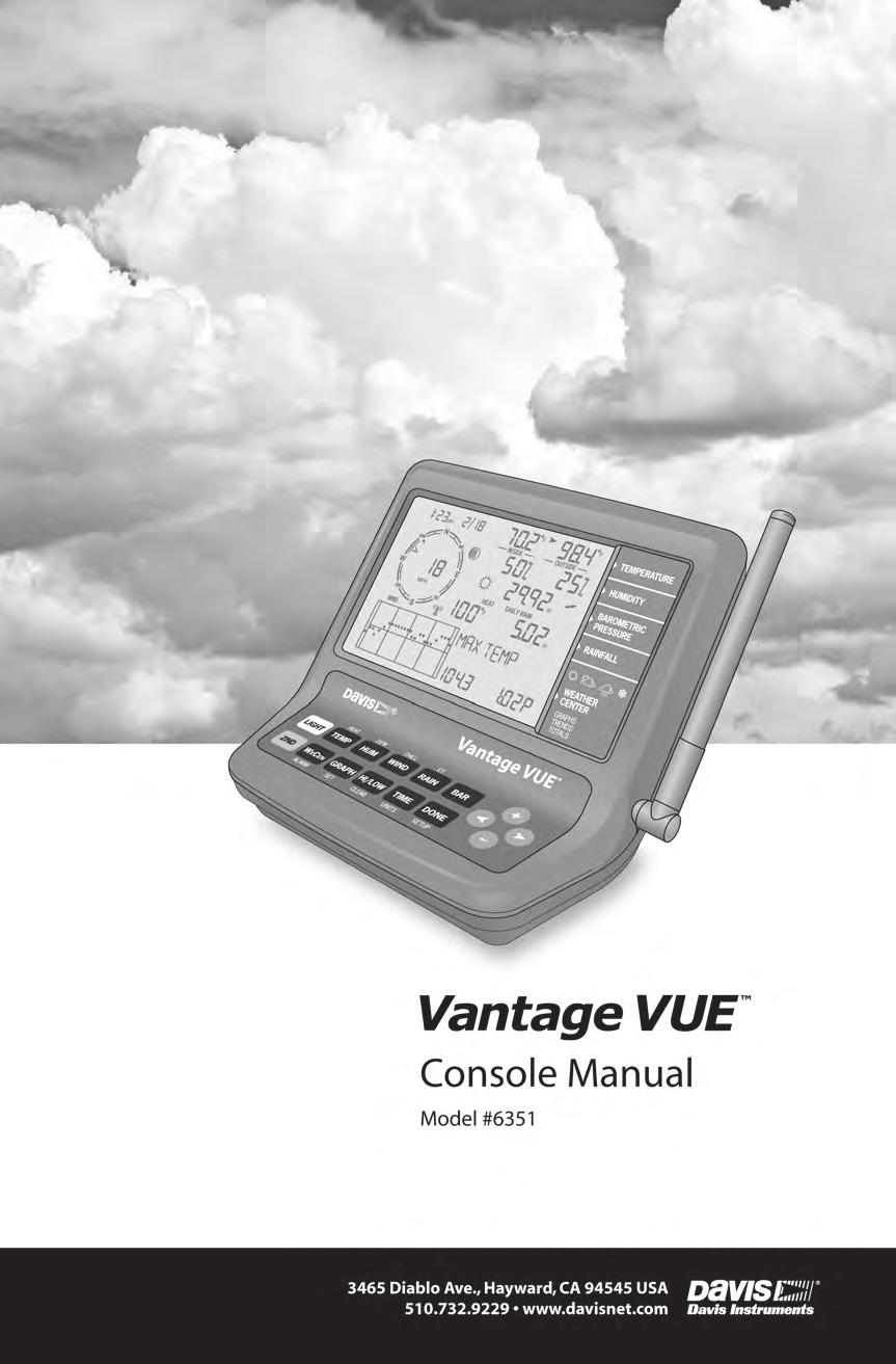
2 FCC Part 15 Class B Registration Warning This equipment has been tested and found to comply with the limits for a Class B digital device, pursuant to Part 15 of the FCC Rules. These limits are designed to provide reasonable protection against harmful interference in a residential installation. This equipment generates, uses, and can radiate radio frequency energy and, if not installed and used in accordance with the instructions, may cause harmful interference to radio communications. However, there is no guarantee that interference will not occur in a particular installation. If this equipment does cause harmful interference to radio or television reception, which can be determined by turning the equipment on and off, the user is encouraged to try to correct the interference by one or more of the following measures: Reorient or relocate the receiving antenna. Increase the separation between the equipment and receiver. Connect the equipment into an outlet on a circuit different from that to which the receiver is connected. Consult the dealer or an experienced radio/tv technician for help. Changes or modification not expressly approved in writing by Davis Instruments may void the warranty and void the user's authority to operate this equipment. FCC ID: IR2DWW6351 IC: 3788A-6351 EC EMC Compliance This product complies with the essential protection requirements of the EC EMC Directive 2004/108/EC; Low Voltage Directive 2006/95/EC; and Eco-Design Directive 2005/32/EC >0.5 watt no-load adaptor. RoHS Compliant Vantage Vue Console Manual Document Part Number: Rev. D, June 1, 2011 For Vantage Vue Consoles #6351 And Vantage Vue Weather Stations #6250, 6357 Vantage Vue and Vantage Pro2 are trademarks of Davis Instruments Corp., Hayward, CA. Davis Instruments Corp All rights reserved. Davis Instruments Quality Management System is ISO 9001 certified. Information in this document subject to change without notice Diablo Avenue, Hayward, CA U.S.A Fax: info@davisnet.com
3 Table of Contents Welcome to Vantage Vue...1 Console Features: Keyboard & Display... 1 In This Manual... 2 Vantage Vue System Installation Steps... 2 Installing the Console...3 Powering the Console... 3 Installing Batteries... 3 Installing the AC Power Adapter (Optional)... 4 Console Location... 4 Table & Shelf Placement... 5 Wall Mounting... 5 Using Your Weather Station...6 Console Modes... 6 Setup Mode... 6 Setup Mode Commands... 6 Screen 1: Time & Date... 7 Screen 2: Time Zone... 7 Screen 3: Daylight Saving Settings... 8 Screen 4: Daylight Saving Status... 8 Screen 5: Active Transmitters... 8 Screen 6: Configuring Transmitter IDs... 9 Screen 7: Retransmit Screens 8 and 9: Latitude and Longitude Screen 10: Elevation Screen 11: Barometric Reduction Setting Screen 12: Wind Cup Type (Optional) Screen 13: Rain Collector Screen 14: Rain Season Screens 15 and 16: Cooling and Heating Degree Day Base Screens 17 and 18: Commentary and Key Beep Screen 19: Baud Rate (Optional) Exiting Setup Mode Clear All Command Current Weather Mode Current Weather Mode Commands Displaying Weather Variables Time & Date, Sunrise & Sunset Time, Moon Phase, Forecast Icons Wind Speed and Direction Inside and Outside Temperature Humidity Barometric Pressure Pressure Trend Wind Chill i
4 Dew Point Heat Index Rain Evapotranspiration (ET) (Optional) Weather Center Light Selecting Units of Measure Calibrating, Setting, and Clearing Variables Calibrating Temperature and Humidity Calibrating Wind Direction Reading Calibrating Barometric Pressure Calibrating Rain Setting Weather Variables Clearing Weather Variables Accumulations & Calibrations Clear All Command Highs and Lows Mode Viewing Highs and Lows Alarm Mode Special Alarms Setting Alarms Setting the Time Alarm Clearing Alarm Settings Silencing Alarms Changing Alarm Sound Graph Mode Viewing Graphs Troubleshooting and Maintenance...36 Vantage Vue Troubleshooting Guide Troubleshooting Reception Problems Check Console Reception Console Diagnostic Mode Diagnostic Screen Commands Screen 1: Statistical Diagnostic Screen Screen 2: Reception Diagnostic Screen Console Maintenance Changing Batteries Console Firmware Versions One Year Limited Warranty Contacting Davis Technical Support Appendix A: Weather Data...42 Appendix B: Specifications...47 Appendix C: Wireless Repeater Configuration...51 ii
5 Chapter 1 Welcome to Vantage Vue The console of your new Vantage Vue wireless weather station displays and records your station s weather data, provides graph and alarm functions, and interfaces to a computer using our optional WeatherLink software. Your Vantage Vue station also includes an outdoor Integrated Sensor Suite (ISS) that transmits outside sensor data to the console via a low-power radio. The console displays all the information coming from the ISS in an easy-to-use format. It can also receive data from a Davis Vantage Pro2 weather station. The Vantage Vue Quick Reference Guide included with your station provides an easy-to-use reference for most console functions. Console Features: Keyboard & Display HEAT DEW CHILL ET LIGHT TEMP HUM WIND RAIN BAR 2ND WXCEN GRAPH HI/LOW TIME DONE ALARM SET CLEAR UNITS SETUP Vantage Vue Keyboard Use the keyboard to access and scroll through current and historical data for individual variables, set and clear alarms, enter calibration values, set up and view graphs, and view detailed weather information available for each variable. The keyboard consists of 12 command keys and four navigation keys. A weather variable or console command is printed on each command key. Just HEAT press a key to select the variable or function printed on that key. TEMP Each command key also has a secondary function which is printed above the first row of keys or below the second row of keys. To select the secondary function, press and release 2ND and then immediately press the key for that function. 2ND After pressing 2ND, the 2nd icon displays above the moon phase icon on the screen indicating that all secondary key functions are enabled. Keys resume normal operation after the icon disappears (about 7-8 seconds). The + and - navigation keys along with the < and > navigation keys are used to select command options, adjust values, and to provide additional functions when used in combination with a command key. An arrow appears next to the variable selected in the display. 1
6 Console Features: Keyboard & Display In Current Weather Mode, the display shows the time and date, the likely forecast within the next 12 hours, current moon phase, and weather information for up to 8 different weather variables at a time. It also displays additional information pertinent to a selected variable in the Weather Center in the bottom right section of the console screen. Time & Date Sunrise/Sunset Arrow shows which variable is selected Inside & Outside Temperature Moon phase, alarm, & forecast icons Wind Compass Rose Antenna icon shows active transmission W NW SW WIND am N S NE SE E CHILL INSIDE F F F OUTSIDE in RAIN RATE in/hr Inside & Outside Humidity Barometric Pressure & Trend Rain data & ET* Wind Chill/Heat Index/Dew Point Graph of selected variable Weather Center with additional information In This Manual *ET, optional, available only when used with a Vantage Pro2 Plus or a Vantage Pro2 with Solar Radiation sensor. This manual contains all the information you will need to power, setup, and use your console. It also includes a troubleshooting section for solving some basic console issues. See Installing the Console on page 3 for information on powering and placing or mounting your Vantage Vue console. See Setup Mode on page 6 for information on configuring and setting up your console. See Current Weather Mode on page 15 for information on displaying current weather information. See Troubleshooting and Maintenance on page 36 for information on troubleshooting console issues and routine maintenance. Vantage Vue System Installation Steps Prepare the Integrated Sensor Suite (ISS) for Installation. See your Vantage Vue Integrated Sensor Suite Installation Manual. Install, power and setup the console Mount the ISS 2
7 Chapter 2 Installing the Console The Vantage Vue console is designed to give extremely accurate readings. As with any precision instrument, use care in its assembly and handling. Although installing the console is relatively simple, following the steps outlined in this chapter and assembling the Vantage Vue correctly from the start will help ensure that you enjoy all of its features with a minimum of time and effort. Powering the Console The Vantage Vue console does not require the use of an AC adapter. You may use the included adapter if you wish, but three C-cell batteries (not included) should power a wireless console for up to nine months. You can use either of these or both together, with the batteries providing backup power for the adapter. Note: The console will display messages if any of your system s batteries are low. LOW CONSOLE BATTERIES: Replace the console batteries LOW BATTERY TRANSMITTER (ID#): Replace the battery in your outdoor Integrated Sensor Suite (ISS) or any optional transmitting station you may have added. Installing Batteries 1. Remove the battery cover located on the back of the console by pressing down on the two latches at the top of the cover. Installing batteries into the Vantage Vue 2. Insert three C batteries into the battery channels as shown. 3. Place the battery cover back onto the console and click it closed. 4. Check to make sure the console runs through a brief self-test procedure successfully. On power up, the console displays all the LCD segments and beeps three times (four times if you have a data logger plugged in). A message displays at the bottom of the console, followed by the first screen of Setup Mode. Press DONE to skip the message and enter into Setup Mode. Setup Mode guides you through steps required to configure the station. See Setup Mode on page 6 for more information. Note: The console does not recharge the batteries. Because of this, and because NiCad batteries do not power the console as long as alkaline batteries, we do not recommend using NiCad batteries. 3
8 Console Location Installing the AC Power Adapter (Optional) 1. Find the power jack located on the left side of the console case. 2. Insert the power adapter plug into the console power jack, then plug the other end of the adapter into an appropriate power outlet. 3. Check to make sure the console runs through a brief self-test procedure successfully. See Installing Batteries on page 3 for information on the self-test procedure. Note: When using an AC power adapter, be sure to use the power adapter supplied with your Vantage Vue console. Your console may be damaged by connecting the wrong power adapter. You must use AC power when using WeatherLinkIP. Console Location Plugging in the AC adapter Place the console in a location where the keyboard is easily accessible and the display is easy to read. For more accurate readings, follow these suggestions. Avoid placing the console in direct sunlight. This may cause erroneous inside temperature and humidity readings and may damage the unit. Avoid placing the console near radiators or heating/air conditioning ducts. If you are mounting the console on a wall, choose an interior wall. Avoid exterior walls that tend to heat up or cool down depending on the weather. Avoid positioning a wireless console near large metallic appliances such as refrigerators, televisions, heaters, or air conditioners. The console antenna does not rotate in a complete circle. Avoid forcing the console antenna when rotating it. Be aware of possible interference from cordless phones or other devices. To prevent interference, maintain a distance of 10 feet (3 meters) between the Vantage Vue console and a cordless phone (handset and base). 4
9 Console Location Table & Shelf Placement The console comes with a kickstand so that the console can be displayed on any flat surface. To install the kickstand: 1. Locate the two keyholes on the back of the console. 2. Place the two round tabs on the kickstand into the two keyholes and slide the kickstand up into place. 3. Install the two round rubber feet on the bottom of the console. 4. Install the two rubber channel feet on the kickstand. Securing the kickstand Installing the rubber feet Wall Mounting The console mounts to the wall using two keyholes located on the back of the case (the same two keyholes are used to hold the console kickstand in place) and two #6 x 1'' pan head self-threading screws included in the hardware kit. To mount the console on a wall: 1. Use a ruler to mark two mounting hole positions on the wall 4 15 / 16 '' inches (125 mm) apart. Use the guide holes on the kickstand as a template for the keyhole spacing. 2. Use a drill and a 3 / 32 or 7 / 64 '' (2.4 or 2.8 mm) drill bit to drill two pilot holes for the screws. 3. Using a screwdriver, drive the two #6 x 1'' pan head self-threading screws into the wall. Leave at least 1 / 8 '' (3 mm) between the wall and the heads of the screws. Mounting the console on a wall 4. Guide the two keyholes on the back of the console over the two screws. 5
10 Chapter 3 Using Your Weather Station The console LCD screen and keyboard provide easy access to your weather information. The LCD display shows current and past weather conditions as well as a forecast of future conditions. The keyboard controls console functions for viewing current and historical weather information, setting and clearing alarms, viewing and/or changing station settings, setting up and viewing graphs, and more. Console Modes The Vantage Vue console operates in five different modes: Setup Mode Current Weather High/Low Alarm Graph Description Use Setup Mode to enter the time, date, and other information required to calculate and display weather data such as latitude, longitude and elevation. See Setup Mode on this page. Use Current Weather Mode to see current weather information, change measurement units, and to set, clear or calibrate weather readings. See Current Weather Mode on page 15. Use High/Low Mode to display the daily, monthly or yearly high and low readings. See Highs and Lows Mode on page 30. Use Alarm Mode to set, clear, and review alarm settings for up to 30 different variables/settings. See Alarm Mode on page 31. Use Graph Mode to display your weather data in the graph section of the console for the current and last 25 time intervals (hours, days, months or even years) in over 50 different graphs. See Graph Mode on page 33. Setup Mode Setup Mode provides access to the station configuration settings that control how the station operates. Setup Mode consists of a series of screens for selecting console and weather station configuration options. Setup Mode Commands Setup Mode displays when the console is first powered. This mode can be displayed at any time to change any of the console options. Use the following commands to enter, exit and navigate Setup Mode: Enter Setup Mode by pressing and releasing 2ND and then SETUP. 2ND DONE Press DONE to move to the next screen in the Setup Mode. Press BAR to display the previous screen in the Setup Mode. SETUP DONE BAR 6
11 Setup Mode Press the < and > keys to move to the different segments and options in the Setup Mode screens. Press the + and - keys to scroll through the different options available. Press 2ND and UNITS to change units of measure when applicable. Exit Setup Mode by pressing and holding DONE until the Current 2ND TIME UNITS Weather screen displays. See Current Weather Mode on page 15 for more information. Screen 1: Time & Date The very first time you power-up the console, you should enter the correct date and local time. To change the time and date: am 1. Press the < and > keys to select the hour, minute, month, day or year segments. The selected time or date setting blinks on and off. YEAR 2. Press the + and - keys to adjust a value up or down. To choose between a 12-hour or 24-hour clock, first select either the hour or minute setting, then press 2ND and immediately press UNITS. This toggles the clock setting between the two clock types. Screen 1: Time & Date To choose between a MM/DD or DD.MM display for the date, first select either the day or month setting, then press 2ND and immediately press UNITS. This switches the console from one date display to the other. 3. Press DONE to move to the next screen. Screen 2: Time Zone The console is pre-programmed with a combination of US time zones and the names of major cities representing time zones around the world. You can also configure your time zone using the Universal Time Coordinate (UTC, also known as Greenwich Mean Time or GMT) offset. Note: UTC offset measures the difference between the time in any time zone and a standard time, set by convention as the time at the Royal Observatory in Greenwich, England. Hayward, California, the home of Davis Instruments, observes Pacific Standard Time. The UTC offset for Pacific Standard Time is -8:00, or eight hours behind Universal Time (UTC). When daylight saving time is observed, an hour is added to the offset time automatically. Use this function in correlation with Screen 3: Daylight Saving Settings on page 8. 7
12 Setup Mode 1. Press the + and - keys to cycle through time zones. 2. If your time zone is not shown, press 2ND then press the + and - keys to set your UTC offset (UTC offset uses 15 minute increments). 3. Press DONE to select the time zone or UTC offset shown on the screen and move to the next screen. Screen 3: Daylight Saving Settings In most of the United States and Canada (except Saskatchewan, Arizona, and Hawaii) and Europe you should use the AUTO Daylight Saving setting. The console is pre-programmed to use the correct starting and stopping dates for daylight saving time in these areas, based on the time zone setting in Screen 2: Time Zone. Weather stations located outside the United States, Canada, and Europe, or in areas that do not observe daylight saving time should use the MANUAL setting. 1. Press the + and - keys to choose Auto or Manual. 2. Press DONE to move to the next screen. Screen 4: Daylight Saving Status Use this screen to either verify the correct automatic daylight saving status or to set daylight saving manually. 1. If the daylight saving setting is MANUAL, press the + and - keys to turn daylight saving time on or off on the appropriate days of the year. This will advance the time by one hour. (Similarly, if you turn daylight saving time off, the time will be set back one hour.) If you have an AUTO daylight saving setting, the console displays the appropriate setting based on the current time and date. 2. Press DONE to move to the next screen. Screen 5: Active Transmitters Screen 5 displays the message Receiving from... and shows the ID number of any transmitters being received by the console. The rest of the screen is blank. If your ISS uses the factory settings and your console is receiving the signal, the screen displays RECEIVING FROM 1. The antenna icon displays if any station s signal has been received. The antenna icon will not display if the console has not received a signal from a station. If you have installed a Vantage Pro2 ISS or Anemometer Transmitter kit, or if a nearby neighbor has a Davis weather station, or if you are receiving from another console in retransmit mode, its ID number will also be displayed. 8
13 Setup Mode Note: A Vantage Vue or Vantage Pro2 ISS or a Vantage Pro2 Anemometer Transmitter Kit must be powered for the console to recognize it. Refer to the Integrated Sensor Suite Installation Manual or other station manual for more information. It may take several minutes for the console to acquire and display a transmitter ID after power is applied to both units. 1. Make a note of the station number(s) listed on the screen. 2. Press DONE to move to the next screen. Screen 6: Configuring Transmitter IDs Setup Screen 6 allows you to change the ISS transmitter ID and to add or remove optional transmitter stations. The default transmitter ID setting is 1 VUE ISS (refers to a Vantage Vue ISS), which is appropriate for most installations. If you are using only the Vantage Vue ISS with ID 1 press DONE to move to the next screen. Note: Typically, you can use the default transmitter ID setting of 1 unless a nearby neighbor has a Vantage Pro2 or Vantage Vue station that uses transmitter ID 1. If you wish to change this default transmitter ID: 1. Press the < and > keys to select a transmitter ID. When you select a transmitter ID (1-8), the ID number is displayed on the screen as well as its current configuration (OFF, VUE ISS, VP2 ISS or WIND). 2. Press the + or - keys to toggle console reception of signals from transmitters using that ID on and off. Note: Make sure any unused ID numbers are set to OFF. To change the station type for the transmitter ID: 1. Press GRAPH to change the type of station assigned from VUE ISS to VP2 ISS or WIND. VUE ISS - Refers tot the Vantage Vue ISS (whether direct transmission or retransmission from another console). VP2 ISS - Refers to the Vantage Pro2 ISS (whether direct transmission or retransmission from another console). WIND - Refers to an optional Anemometer Transmitter Kit (direct transmission only). 2. Press DONE to move to the next screen. Note: This screen contains functionality for enabling repeaters. If the word Repeater displays in the right corner of the screen and you are not using repeaters as part of your network, see Clearing Repeater ID on page 51. If you are using repeaters as part of your network see Wireless Repeater Configuration (Appendix C) on page 51. 9
14 Setup Mode Screen 7: Retransmit The console can take data it receives from all three station types and retransmit it to other Vantage Vue or Vantage Pro2 consoles using the retransmit feature. By toggling the feature on, the console becomes another transmitter that requires its own unique ID to transmit the data received from the ISS. 1. Press the + or - key to turn the retransmit function on and off. The first available transmitter ID not assigned to a station in Screen 6: Configuring Transmitter IDs will be assigned to the console. Note: Make sure no other wireless Davis weather station is transmitting on the same ID. The Vantage Vue console can only retransmit data from either a Vantage Vue ISS or console Vantage Pro2 ISS or console. Data from other stations will not retransmit. When retransmit has already been enabled, pressing the < or > keys changes the transmitter ID used for retransmit. 2. Use the > key to scroll through the list of available transmitter IDs and select the ID for your console. 3. Press DONE to move to the next screen. Note: Make a note of the ID selected for retransmit and the transmitter type (ISS or VP2) the console is retransmitting. Make sure the console that is receiving the retransmitted data is configured to the correct transmitter type. See Screen 6: Configuring Transmitter IDs on page 9 for more information. Screens 8 and 9: Latitude and Longitude The console uses latitude and longitude to determine your location, allowing it to adjust the forecast and calculate the times for sunset and sunrise. Latitude measures distance north or south of the equator. Longitude measures distance east or west of the Prime Meridian, an imaginary line running north and south through Greenwich, England. If you do not know your latitude and longitude, there are several ways to find out. Many atlases and maps include latitude and longitude lines. You can also talk to the reference department of your local library, call your local airport, or search on the Internet. An easy way to find your latitude and longitude is to download Google Earth ( The more accurate you are, the better; however, a reasonable estimate will work, too. 1. Press the < and > keys to move between fields. 2. Press the + and - keys to change the settings up or down. 3. Press 2ND and then UNITS to select between SOUTH or NORTH. 4. Press DONE to move to the Longitude screen. 10
15 1. Press the < and > keys to move between fields. 2. Press the + and - keys to change the settings up or down. 3. To select EAST or WEST, press 2ND, then UNITS. 4. Press DONE to move to the next screen. Screen 10: Elevation Setup Mode Your station s elevation is used in determining your barometric pressure. Meteorologists standardize barometric pressure data to sea level so that surface readings are comparable, whether they are taken on a mountainside or by the ocean. To use this same standardization and ensure consistent readings, enter your elevation in this screen. If you do not know your elevation, there are several ways to find out. Many atlases and almanacs include elevation for cities and towns. You can also check with the reference department of your local library, or use Google Maps (in terrain view). The more accurate you are, the better; but a reasonable estimate works too. 1. Press the < and > keys to move from one value to another. 2. Press the + and - keys to adjust a numeral up or down. 3. To switch between feet and meters, press 2ND then press UNITS. 4. If your location is below sea level, such as in Death Valley or the Salton Sea, first enter the elevation as a positive number. Select the 0 immediately to the left of the left-most nonzero digit (the second zero from the left in 0026, for example, or the first zero from the left in 0207) and press and hold the + or - key until it cycles from 0 to 9 and then -. Note: You can only set the elevation to negative after you have entered a non-zero digit and when the zero in the position immediately to the left of the left-most non-zero digit has been selected. If you need to enter an elevation below -999 feet, select meters and enter the converted number (multiply your elevation in feet by ). 5. Press DONE to move to the next screen. Screen 11: Barometric Reduction Setting The Barometric Reduction Setting screen indicates the method by which barometric pressure is to be determined and calculated. The factory default is NOAA, but in this screen you may select a different method. 11
16 Setup Mode To change the barometric reduction setting: 1. Press + or - to change the barometer reduction setting type: NOAA (Default Setting) The barometer is reduced to sea level using a technique that factors in the humidity and temperature of the column of air. ALT SETTING (Altimeter Setting) The barometer is reduced to sea level using a standard column of air, often referred to as a standard atmosphere. NONE Reports a raw barometric pressure reading unadjusted for elevation/altitude. 2. Press DONE to move to the next screen. Note: See Calibrating Barometric Pressure on page 28 to learn how to fine-tune your barometric pressure to a local source. Screen 12: Wind Cup Type (Optional) The Wind Cup Type screen displays if you selected VP2 or WIND in Screen 6 of the Setup Mode. This screen does not display if you have selected a Vantage Vue ISS. See Screen 6: Configuring Transmitter IDs on page 9 for more information. The Wind Cup Type screen contains three options: LARGE, SMALL, or OTHER. In most Vantage Pro2 anemometer or ISS Installations, LARGE is the cup type that is shipped with all Vantage Pro2 anemometers. See the Vantage Pro2 Console Manual for more information. To change the wind cup type: 1. Press the + and - keys to scroll through the three wind cup options. 2. Press DONE to use the selected setting and move to the next screen. Note: Do not change the wind cup type from LARGE if you are using the wind cups that were shipped with your system. Screen 13: Rain Collector The tipping spoon in the Vantage Vue rain collector has been calibrated at the factory to measure either 0.01'' or 0.2mm of rain with each tip depending on the model. This screen is used at the factory for this calibration. The typical user will not need to change it and can skip this screen. in Note: This screen will not change the units on your display. To change the units on your display from inches to mm, or vice versa, see Selecting Units of Measure on page
17 Screen 14: Rain Season Setup Mode Because rainy seasons begin and end at different times in different parts of the world, you must specify the month you wish your yearly rain data to begin. January 1 st is the default setting. The date the rain season begins affects yearly rain rate highs and lows as well as the yearly rain totals. 1. Press the + and - keys to select the month for the start of the rainy season. 2. Press DONE to move to the next screen. Note: This setting determines when the yearly rain total is reset to zero. Davis Instruments recommends a January rain season setting (the default), unless you reside on the west coast of the United States, the Mediterranean Coast, or experience dry winters in the southern hemisphere. If so, change the rain season setting to July 1 st. If you are performing hydrology studies in any of these climates in the Northern Hemisphere, change the rain season setting to October 1 st. Screens 15 and 16: Cooling and Heating Degree Day Base The Cooling and Heating Degree Day Base screens let you determine the temperature base that is used to calculate the number of cooling or heating degree days. A cooling degree day is used to determine the amount of energy or fuel used to keep a structure like your home or business cool. A heating degree day is used to determine the amount of energy or fuel used to keep a structure like your home or business warm. One cooling degree/day is the amount of cooling required to keep a structure cool when the outside temperature remains 1 F above the 65 F threshold for 24 hours. One cooling degree/ day is also the amount of cooling required when the temperature remains 24 F above the 65 F threshold for one hour. One heating degree/day is the amount of heat required to keep a structure warm when the outside temperature remains 1 F below the 65 F threshold for 24 hours. One heating degree/ day is also the amount of heat required when the temperature remains 24 F below the 65 F threshold for one hour. The cooling and heating degree days (similar to growing degree days and chilling requirement in agriculture) are used for agricultural purposes, to determine crop planting, disease and pest management and harvesting. Our optional WeatherLink software (#6510USB, 6510SER, 6555) makes advanced calculations using the degree day totals. Our optional Agricultural/Turf Management Software Module (#6511) adds the special reporting features to the WeatherLink software that include evapotranspiration and chilling requirement. The Cooling and Heating Degree Day Bases are used to determine the Cooling Degree Day Daily Total and Heating Degree Day Daily Total, which display as part of the Weather Center when the outside temperature variable is selected. See Inside and Outside Temperature on page 18 for more information. A base setting for both the Cooling and Heating Degree Day temperature is not set at the factory, allowing you to choose. A base of 65 F (15 C in Europe) is suitable for most applications. 13
18 Setup Mode To set your cooling degree day base: 1. Press 2ND and SET. The value of 65 appears. Use the < and > keys to select a segment of the value. 2. Press the + and - keys to adjust the value of the selected segment. 3. Press 2ND and UNITS to change the temperature setting between Fahrenheit and Celsius. 4. Press DONE to move to the next screen. The Heating Degree Day Base displays: To set your heating degree day base, follow steps 1 through 4 above. To turn the degree day function off, press 2ND and then clear. The value changes to dashes. F F Note: If a base temperature is displayed, degree day data is being accumulated. If the value shows dashes, the degree day function is off and will not appear in the Weather Center. Screens 17 and 18: Commentary and Key Beep Commentary refers to the extra information and comments on current weather conditions, such as lunar and solar eclipses, meteor showers and other information, that displays on the console in the Weather Center. Key Beep is a sound that indicates a key has been pressed. (It is different from the error sound. To change this sound, See Changing Alarm Sound on page 33.) These functions can be turned off or on. 1. Press the + and - keys to toggle the setting to OFF or ON. 2. Adjust key beep volume using the < and > keys. 3. Press DONE to move to the next screen. Screen 19: Baud Rate (Optional) The Baud Rate screen displays only if a WeatherLink data logger is installed in the console. The console uses a serial, USB, or Ethernet port to communicate with a computer. If you are connecting the console directly to your computer via USB or Ethernet connection, leave the setting at 19200, the highest rate for the port. Note: The baud rate setting on your console must match the baud rate setting in the software on your computer. If you are using WeatherLink for Vantage Vue, refer to WeatherLink Help for instructions on setting the serial port baud rate on your computer. 14
19 Current Weather Mode 1. Press the + and - keys to select the baud rate. Your Vantage Vue console supports baud rates of 1200, 2400, 4800, 9600, 14400, and Press DONE to save the baud rate settings. Exiting Setup Mode You have successfully completed all the screens in the Setup Mode. To exit Setup Mode, press and hold DONE for several seconds until the Current Weather screen appears. Clear All Command After you have completed the above setup procedures and have exited the Setup Mode and once the Vantage Vue ISS, Vantage Pro2 ISS or Anemometer Transmitter kit has been installed, please use the Clear All command before putting your weather station into service. The Clear All command clears all stored high and low weather data including monthly and yearly highs and lows, and clears the alarm settings. The command is recommended to properly clear the console of any erroneous data when first putting your station into use. 1. Press WIND to display wind speed on the console. 2. Press 2ND, then press and hold CLEAR for at least six seconds. 3. Release CLEAR when you see CLEARING NOW displayed at the bottom of the console s screen. Current Weather Mode In the Current Weather Mode you am F F can display the current data N INSIDE OUTSIDE readings from your station, select NW NE units of measure, and calibrate, set, or clear weather variables. W E in You can see up to eight weather CHILL RAIN RATE SW SE F variables on the screen at the S in/hr WIND same time, as well as the time and date, moon phase and forecast icons, and a graph of the currently selected variable. Some variables are always visible on the console screen while most variables share their location with one or more variables. You can select any variable not currently on the screen to display it. 15
20 Displaying Weather Variables Current Weather Mode Commands Select a weather variable to display its data on the screen if it isn t already visible, or to graph the data available for that variable. Weather variables are selected via the console command keys: If the variable is printed on a key, press the key to select the variable. TEMP HUM WIND RAIN BAR The same field can display multiple values for each variable. Press the variable key to scroll through all the values Multiple variables may share the same field on the display. SW MPH SE CHILL F RAIN RATE WIND S in/hr DEW HEAT F F Wind chill, dew point, heat index share the same field in Current Weather Mode If a variable is printed above or below a key, first press and release 2ND, then quickly press the key below the printed variable to select that variable. HEAT DEW CHILL ET 2ND LIGHT 2ND TEMP HUM WIND RAIN BAR WXCEN GRAPH HI/LOW TIME DONE ALARM SET CLEAR UNITS SETUP After pressing 2ND, the 2nd icon displays on the screen for eight seconds. Key secondary functions are enabled during this time. The keys return to normal operation after the icon disappears. Select a variable and press WxCEN to display information pertinent to the selected variable in the Weather Center. Continue to press WxCEN to scroll through all the information available for the variable. You can also select any variable currently displayed on the LCD screen using the navigation keys. Press the + key to move the selection arrow up the screen. Press the - key to move it down the screen. Push the < key to move it left and push the > key to move it right. Displaying Weather Variables 2ND WXCEN The variables are arranged below in the order they are viewed on the console screen; left to right, top to bottom, starting with Time and Date. 16
21 Displaying Weather Variables Time and Date, Sunrise and Sunset Time, Moon Phase, Forecast Icons The time and date display in the upper left hand corner of the console screen, above the wind compass rose. Press TIME to display the sunrise and sunset time for the current day. Press TIME again to redisplay the time and date. TIME The phase of the moon is described in the Weather Center section of the console when the sunrise and sunset times are displayed. The moon phase icon corresponds to the moon phase description in the Weather Center. See Moon Phases on page 42. The current forecast icon displays underneath the current moon phase icon. The forecast icons show what weather conditions may occur within the next 12 hours. See Forecast on page 43 for more information on the forecast icons and descriptions of the forecasted weather they represent. am Sunset N NE Note: See Screen 1: Time & Date on page 7 to change the console time and date or to select a 12- or 24-hour clock. Wind Speed and Direction Wind speed and direction are displayed in the compass rose in the upper left section of the console screen: Sunrise W NW SW WIND MPH S SE E pm DEW INSIDE F OUTSIDE Sunrise and sunset times, moon phase and forecast icons, with the moon phase listed in the Weather Center F RAIN in DAY in F am F F N INSIDE OUTSIDE NW NE W E mb SW MPH SE CHILL F RAIN RATE WIND S in/hr Wind speed, direction and wind information displayed in the Weather Center 1. Press WIND to select wind speed. Wind speed may be displayed in miles per hour (MPH.), kilometers per hour (km/h), meters per second (m/s), or knots. See Selecting Units of Measure on page 26 for more information on changing the unit of measure. The graph will show the current and last 25 hours of readings. WIND 17
22 Displaying Weather Variables A solid arrow within the compass rose indicates the current wind direction. Open arrows indicate up to six different 10-minute dominant wind directions to provide a history of the dominant wind directions for the past hour. 2. Press WIND a second time to display the wind direction in degrees instead of the wind speed. Each additional WIND key press toggles the display between wind speed and wind direction in degrees. When displayed in degrees, due north displays as 360. If the solar panel on your ISS is not facing due south, you should recalibrate the wind direction reading on your console. See Calibrating Wind Direction Reading on page Press WxCEN to display the weather information available for wind in the Weather Center. 4. Press WxCEN multiple times to scroll through all the wind-related Weather Center screens, which include: Maximum Wind Speed Displays the highest wind speed recorded for the day. Includes the time the speed was recorded. Last 10 Minute Gust Displays the high wind gust in the last 10 minutes with the direction of the highest gust displayed in degrees. Average Wind Speed Displays the average speed over the past two minutes and over the past ten minutes. Beaufort Scale Toggles between a description of the wind speed and how the wind ranks on the Beaufort Scale. (See Beaufort Scale on page 44 for more information.) Wind Direction Displays the current wind direction in degrees. Inside and Outside Temperature Inside and outside temperature are displayed in the top right portion on the console screen. The inside temperature is located above the word INSIDE and the outside temperature is located above the word OUTSIDE. W NW SW WIND pm N MPH S NE SE E 315 NW 270 W 225 SW CHILL INSIDE F 360 N 180 S F RAIN RATE 45 NE 90 E 135 SE OUTSIDE mb in/hr F Inside and outside temperature with information displayed in the Weather Center 1. Press TEMP to select the outside temperature. TEMP Temperature may be displayed in degrees Fahrenheit ( F) or Celsius ( C). Temperatures can also be displayed in degrees or in tenths of a degree. See Selecting Units of Measure on page 26 for more information on changing the unit measure or displaying the temperature in tenths of a degree. If the unit of measure is 18
23 Displaying Weather Variables changed for inside or outside temperature, the unit of measure also changes for all temperature-related weather variables, such as wind chill, dew point and heat index. Note: The unit of measure also affects the cooling degree day and heating degree day bases and the value entered in both screens is automatically converted to the unit of measure selected. Check the values for both of these bases in the Setup Mode to make sure the value is still accurate for the new unit of measure. See Screens 15 and 16: Cooling and Heating Degree Day Base on page 13 for more information. 2. Press WxCEN to display weather information available for the outside temperature variable in the Weather Center. 3. Press WxCEN multiple times to scroll through all the outside-temperature-related Weather Center screens, which include: Maximum Temperature Displays the highest temperature for the day with the time the temperature was recorded. Minimum Temperature Displays the lowest temperature for the day with the time the temperature was recorded. Temperature Change Per 24 Hours Displays the difference between the temperature currently recorded and the temperature recorded at the same time the day before. (Updated on the hour.) Temperature Change Per Hour Displays the difference between the temperature currently recorded and the temperature recorded the hour before. (Updated every 15 minutes.) Maximum Outside Temperature Today and Over the Last 25 days Displays the highest temperature today and over the last 25 days and the date the temperature was recorded. Minimum Outside Temperature Today and Over the Last 25 days Displays the lowest temperature today and over the last 25 days and the date the temperature was recorded. Number of Cooling Degree Days Displays the number of cooling degree days logged on the console since it was first powered up or the value was reset. (Displays only if a threshold has been set.) Number of Heating Degree Days Displays the number of heating degree days logged on the console since it was first powered up or the value was reset. (Displays only if a threshold has been set.) 4. Press TEMP again to select the inside temperature. 5. Press WxCEN to display the weather information available for the inside temperatures in the Weather Center. 6. Continue pressing WxCEN to scroll through all the inside-temperature- related Weather Center screens, which include: Maximum Temperature Displays the highest inside temperature for the day with the time the temperature was recorded. Minimum Temperature Displays the lowest inside temperature for the day with the time the temperature was recorded. 19
24 Displaying Weather Variables Humidity Inside and outside humidity are displayed in the top right portion on the console screen, below the temperature variables. The inside humidity is located below the word INSIDE and the outside humidity is located below the word OUTSIDE. NW W SW WIND am C C N INSIDE OUTSIDE NE E mb MPH CHILL RAIN RATE SE C S in/hr Inside and outside humidity with information displayed in the Weather Center 1. Press HUM to select outside humidity. Humidity is displayed in percent relative humidity. HUM 2. Continue pressing WxCEN to display the information available for outside humidity in the Weather Center and to scroll through the outside humidityrelated Weather Center screens, which include: Maximum Outside Humidity Displays the highest humidity measurement for the day and the time it was recorded. Minimum Outside Humidity Displays the lowest humidity measurement for the day and the time it was recorded. 3. Press HUM a second time to select inside humidity. 4. Press WxCEN to display the information available for inside humidity in the Weather Center. Continue pressing WxCEN to scroll through the inside humidity-related Weather Center screens, which include: Maximum Inside Humidity Displays the highest inside humidity measurement for the day and the time it was recorded. Minimum Inside Humidity Displays the lowest inside humidity measurement for the day and the time it was recorded. Barometric Pressure NW NE Barometric pressure and pressure trend display below inside and outside humidity. W SW WIND MPH S SE E CHILL F RAIN RATE in in/hr Barometric Pressure with information displayed in the Weather Center 20
25 Displaying Weather Variables 1. Press BAR to select barometric pressure. Barometric pressure may be displayed in inches (in), millimeters (mm), millibars (mb) or hectopascals BAR (hpa). See Selecting Units of Measure on page 26 for more information on changing the unit measure. 2. Press WxCEN to display the information available for the barometric pressure trend in the Weather Center. 3. Continue pressing WxCEN to scroll through all the barometric pressure-related Weather Center screens, which include: Barometric Pressure Change Per 24 hours Displays the difference between the barometric pressure currently recorded and the barometric pressure recorded at the same time yesterday. (Updated on the hour.) Maximum Barometric Pressure Displays the highest barometric pressure reading for the day and the time the measurement was recorded. Minimum Barometric Pressure Displays the lowest barometric pressure reading for the day and the time the measurement was recorded. Altimeter Setting Displays the barometric pressure that would display if ALT SET- TING was selected in Screen 11: Barometric Reduction Setting. The barometric pressure reading and the altimeter setting reading will be the same if the altimeter setting was selected. See Screen 11: Barometric Reduction Setting on page 11 for more information. Absolute Pressure Displays the barometric pressure that would display if NONE was selected in Screen 11: Barometric Reduction Setting. The barometric pressure reading and the absolute pressure reading will be the same if none was selected. See Screen 11: Barometric Reduction Setting on page 11 for more information. Barometric Pressure Trend Describes the current barometric trend and the numeric change in the barometric pressure over the last three hours. The barometric pressure trend listed in the Weather Center corresponds to the pressure trend arrows displayed next to the barometric pressure variable. The trends are: Bar Rising Rapidly Refers to a rise in pressure greater than or equal to 0.06'' (2 hpa) over the last three hours. Bar Rising Slowly Refers to a rise in pressure greater than or equal to 0.02'' (0.7 hpa) but less than 0.06'' (2 hpa) over the last three hours. Bar Steady Refers to no change or a change of less than 0.02'' (0.7 hpa) either rising or falling over the last three hours. Bar Falling Slowly Refers to a fall in pressure greater than or equal to 0.02'' (0.7 hpa) but less than 0.06'' (2 hpa) over the last three hours. Bar Falling Rapidly Refers to a fall in pressure greater than or equal to 0.06'' (2 hpa) over the last three hours. 21
26 Displaying Weather Variables Pressure Trend The pressure trend arrow indicates the current barometric trend, measured over the last three hours. The pressure trend is updated every 15 minutes. The pressure trend requires three hours of data in order to be calculated so it won t display right away on a new station. The pressure trend is indicated on the console screen, as long as the required data is available. Wind Chill Wind chill shares the same section on MPH CHILL the console as dew point and heat SW SE F index, below the barometric pressure WIND S variable, next to the wind compass rose. RAIN RATE in/hr Wind chill with information displayed in the Weather Center 1. Press 2ND then press CHILL to select wind chill. Wind chill is displayed in either Fahrenheit ( F) or Celsius ( C) in whole degrees. See Selecting Units of Measure on page 26 for more information on changing the unit of measure. 2ND CHILL WIND If the unit of measure for any temperature-related weather variable is changed, the unit of measure also changes for all temperature-related variables. See Inside and Outside Temperature on page 18 for more information. The console uses the ten-minute average wind speed to calculate wind chill. 2. Press WxCEN to display the weather information available for wind chill in the Weather Center. 3. Press WxCEN twice to scroll through the wind chill-related Weather Center screens, which include: Minimum Wind Chill Displays lowest wind chill measurement for the day and the time it was recorded. Maximum Wind Speed Displays the maximum wind speed for the day and the time it was recorded. Dew Point Dew point (outside only) shares the MPH DEW same section on the console as wind SW SE F RAIN RATE chill and heat index, below the barometric pressure variable, next to the wind compass rose. WIND S in/hr Dew Point with information displayed in the Weather Center 22
27 Displaying Weather Variables 1. Press 2ND then press DEW to select dew point. Dew point is DEW displayed in either Fahrenheit ( F) or Celsius ( C) in whole degrees. 2ND HUM See Selecting Units of Measure on page 26 for more information on changing the unit of measure. If the unit of measure for any temperature-related weather variable is changed, the unit of measure also changes for all temperature-related variables. See Inside and Outside Temperature on page 18 for more information. 2. Press WxCEN to display the weather information available for dew point in the Weather Center. Press WxCEN twice to scroll through the Weather Center screens, which include: Maximum Dew Point Displays the highest dew point measurement for the day with the time it was recorded. Minimum Dew Point Displays the lowest dew point measurement for the day with the time it was recorded. Heat Index Heat index (outside only) shares the same MPH HEAT RAIN RATE section on the console as wind chill and dew SW SE F S in/hr WIND point, below the barometric pressure variable, next to the wind compass rose. Heat Index with information displayed in the Weather Center Press 2ND then press HEAT to display the HEAT heat index. Heat index is displayed in either Fahrenheit ( F) or Celsius 2ND TEMP ( C) in whole degrees. See Selecting Units of Measure on page 26 for more information on changing the unit of measure. If the unit of measure for any temperature-related weather variable is changed, the unit of measure also changes for all temperature-related variables. See Inside and Outside Temperature on page 18 for more information. The Maximum Heat Index (the highest Heat Index measurement recorded for the day) along with the time it occurred displays in the Weather Center section of the console. Rain All the rain values are displayed in the same section on the console below the barometric pressure variable, on the right side. 23
Vantage PRO2 Quick. Reference Guide
 Vantage PRO2 Quick Reference Guide INTRO This Quick Reference Guide will provide you with abbreviated instructions for all functions of the Vantage Pro2 console. For more detailed instructions, see Vantage
Quick Reference Guide
 Vantage PRO Davis Instruments 3465 Diablo Ave, Hayward, CA 94545 U.S.A. Phone (510) 732 9229 Fax (510) 732 9188 www.davisnet.com E-mail: sales@davisnet.com support@davisnet.com Quick Reference Guide Part
Product Description. 1 of 6
 Product Description The 6250 Vantage Vue Wireless Weather Station provides accurate, reliable weather monitoring in a self-contained, easy-to-install system. Designed to provide the weather data you need
Vantage Pro. Console Manual. Weather Station. Product #6310, 6310EU, 6310UK, 6310C, 6310CEU, 6310CUK N NE. S Last 24 hrs Every 1 hr BAROMETER HUM OUT
 Vantage Pro TM Weather Station pm WIND NW N NE TEMP OUT HUM OUT BAROMETER inmb W E MPH SW SE S Last 24 hrs Every 1 hr N W TEMP IN DAILY RAIN HUM IN CHILL RAIN RATE in/hr S E N in STATION NO.1 Console Manual
Weather Stations. Evaluation copy. 9. Post live weather data on the school s web site for students, faculty and community.
 Weather Stations Computer P6 Collecting and analyzing weather data can be an important part of your Earth Science curriculum. It might even be an ongoing part of your entire course. A variety of activities
Vantage Vue Weather Station
 Vantage Vue Weather Station 6250 6357 6351 VANTAGE VUE The VantageVue (#6250) wireless weather station includes two components: the Integrated Sensor Suite (ISS) (#6357) which houses and manages the external
Website Phone Mobile OVERVIEW Davis Vantage Pro2 Weather Station
 OVERVIEW If you're looking for a superior weather station, the Davis Vantage Pro2 Weather Station is as good as they come! Vantage Pro2 offers the professional weather observer and the serious weather
Professional Wind Station
 Professional Wind Station For online video support: http://bit.ly/laxtechtalk Instructional Manual Model: 7-7BW DC:7 Contents Setup Preparation... Quick Setup... Buttons... Settings... Display Icons...
Cabled Vantage Pro2 & Vantage Pro2 Plus Stations
 W IN D NW N W E SW M P H S NE SE L ast 2 4h rs E ve ry 1 hr N W S E N T EM P O U T TEM P IN F DA ILY R A IN F HUM OU T in HUM IN STATION NO.1 pm BAROMETER CHIL L RAIN TE RA in m b in /h r Cabled Vantage
O P E R A T I N G M A N U A L
 OPERATING MANUAL WeatherJack OPERATING MANUAL 1-800-645-1061 The baud rate is 2400 ( 8 bits, 1 stop bit, no parity. Flow control = none) To make sure the unit is on line, send an X. the machine will respond
Wireless Vantage Pro & Vantage Pro Plus Stations
 WIND NW SW MPH NE SE Last 24 hrs Every 1 hr N W S E N TEMP OUT TEMP IN DAILY RAIN F F HUM OUT in HUM IN STATION NO.1 pm BAROMETER CHILL RAIN RATE inmb F in/hr Wireless Vantage Pro & Vantage Pro Plus Stations
Vantage Pro. Weather Envoy. Installation Manual. Product # 6314 & 6314C
 Vantage Pro Weather Envoy Installation Manual Product # 6314 & 6314C FCC Part 15 Class B Registration Warning This equipment has been tested and found to comply with the limits for a Class B digital device,
Model: WT-3181PL Instruction Manual DC: Indoor/Outdoor Atomic Wall Clock. Get Started
 Model: WT-3181PL Instruction Manual DC: 041614 18 Indoor/Outdoor Atomic Wall Clock Round Battery Cover Get Started Step 1: Remove the round battery cover from the back of the clock. Step 2: Insert 1 fresh
U.S. Atomic Clock & Weather Station. Instruction Manual
 U.S. Atomic Clock & Weather Station Instruction Manual Table of Contents What is Atomic Radio Control?... 2 Parts Diagram... 3 Batteries... 4 Setting the Atomic Time and Date... 4 Setting the Clock...
station) on the serial port
 on the serial port") Connects a Davis VantagePro2 or Vantage Vue to a BACnet network BACnet MS/TP over RS-485 compatible Easy BACnet network configuration via onboard switches Various selectable metric and imperial unit conversions
Connects a Davis VantagePro2 or Vantage Vue to a BACnet network BACnet MS/TP over RS-485 compatible Easy BACnet network configuration via onboard switches Various selectable metric and imperial unit conversions
WS-9018U Wireless Weather Station. Instruction Manual
 WS-9018U Wireless Weather Station Instruction Manual Contents Page 1. Functions of the Weather Station....3 2. Safety notes...3 3. Product features....4 4. Getting started....4 5. Quick Set Up...5 6. Setting
ea980r Digital Anemometer User Manual
 ea980r Digital Anemometer User Manual 1. Overview Thank you for purchasing the ennologic ea980r anemometer, a high quality instrument which measures 8 parameters: Wind Speed (mph, m/s, ft/min, knots, km/h)
Hadrons Desktop U.S. Atomic Clock & Weather Station
 Hadrons Desktop U.S. Atomic Clock & Weather Station SN004 Instructions Read and save these instructions. Dear Sharper Image Customer, Thank you for your purchase of a Sharper Image product. We appreciate
Congratulations on purchasing this WS1516IT Professional Weather Station.
 FAQ WS1516IT Congratulations on purchasing this WS1516IT Professional Weather Station. For your Weather Station to work properly, it must be started correctly, using good quality alkaline batteries, and
Integrated Sensor Suite Installation Manual. Model #6357. Distributed by MicroDAQ.com, Ltd. (603)
") Integrated Sensor Suite Installation Manual Model #6357 3465 Diablo Ave., Hayward, CA 94545 USA 510.732.9229 www.davisnet.com Table of Contents Introduction...1 Included Components and Hardware...1 Vantage
Integrated Sensor Suite Installation Manual Model #6357 3465 Diablo Ave., Hayward, CA 94545 USA 510.732.9229 www.davisnet.com Table of Contents Introduction...1 Included Components and Hardware...1 Vantage
Advanced Weather Station with Wireless Sensor Set Model: WMR90A
 Advanced Weather Station with Wireless Sensor Set Model: WMR0A INTRODUCTION Thank you for selecting the Oregon ScientificTM Advanced Weather Station with Wireless Sensor Set (WMR0A). The base station is
MODE button MAX/MIN button CHANNEL button / C/ F / RCC button SNOOZE / LIGHT button Battery compartment A/C in-jack 3. 4.
 KL4912 Desktop weather station Instruction Manual Introduction This weather station comes with backlight, indoor and outdoor temperature & humidity display, and alarm clock with calendar. Fig. 1 Front
WeatherHawk Weather Station Protocol
 WeatherHawk Weather Station Protocol Purpose To log atmosphere data using a WeatherHawk TM weather station Overview A weather station is setup to measure and record atmospheric measurements at 15 minute
QUICK SET UP MANUAL WEATHER CENTER
 QUICK SET UP MANUAL WEATHER CENTER Using 915MHz wireless transmission of weather data, this unique weather station can be powered using batteries for all your weather needs in the home or office. This
WE RE HERE TO HELP: 1 (844) LIGHTCLOUD
 LIGHTCLOUD") Welcome Controller LCCONTROL20/D10 WE RE HERE TO HELP: 1 (844) LIGHTCLOUD 1 (844) 544-4825 support@lightcloud.com Contents Lightcloud Controller NPT Nut O-ring Instruction Manual Wire Nuts x 4 x 2 Specifications
Welcome Controller LCCONTROL20/D10 WE RE HERE TO HELP: 1 (844) LIGHTCLOUD 1 (844) 544-4825 support@lightcloud.com Contents Lightcloud Controller NPT Nut O-ring Instruction Manual Wire Nuts x 4 x 2 Specifications
What is the maximum distance I can have the remote sensors from the display?
 What is the maximum distance I can have the remote sensors from the display? The maximum open-air distance is 100 meters in a straight line although you should take into account the environment, distance
Rain Collector (# 7852 & 7852M)
") Rain Collector (# 7852 & 7852M) This rain collector can be used with Vantage Pro2 weather stations, including Vantage Pro2, Vantage Pro2 Plus, and the Anemometer/Sensor Transmitter Kit. Note: Model number
Rain Collector (# 7852 & 7852M) This rain collector can be used with Vantage Pro2 weather stations, including Vantage Pro2, Vantage Pro2 Plus, and the Anemometer/Sensor Transmitter Kit. Note: Model number
BERMAD Irrigation. BIC2000 Weather Station SYSTEM GUIDE VERSIONS : BIC ; PC 4.90
 BIC2000 Weather Station SYSTEM GUIDE VERSIONS : BIC2000 3.92; PC 4.90 CONTENTS 1. SYSTEM OVERVIEW 3 2. WEATHER STATION SETUP 4 2.1 ISS AND CONSOLE SETUP 4 2. RF RTU SYSTEM SETUP 5 2.2 BIC2000 WEATHER STATION
CONTENTS. Batteries. La Crosse Technology, Ltd Page 1
 515-1316 FAQS The links below will work in most PDF viewers and link to the topic area by clicking the link. We recommend Adobe Reader version 10 or greater available at: http://get.adobe.com/reader CONTENTS
WS-7038U Wireless 433 MHz Miniature Rain Monitor. Instruction Manual
 WS-7038U Wireless 433 MHz Miniature Rain Monitor Instruction Manual TABLE OF CONTENTS Topic Page Inventory of Contents/ Additional Equipment 3 Quick Set-Up Guide 3 Detailed Set-Up Guide Battery Installation
Wireless Weather Station
 Wireless Weather Station with Software Owner s Manual Please read before using this equipment. ˆ Contents FCC Declaration of Conformity... 3 Features... 3 Preparation... 5 A Quick Look at the Weather Station...
Wireless Vantage Pro2 & Vantage Pro2 Plus Stations
 Wireless Vantage Pro2 & Vantage Pro2 Plus Stations (Including Fan-Aspirated Models) 6152 6162 6153 6163 WIRELESS VANTAGE PRO2 Vantage Pro2 (6152, 6153) and Vantage Pro2 Plus (6162, 6163) Wireless Weather
Instruction Manual. Solar Weather Centre With Wireless Weather Vane. Product Code: WS5056C. Solar Powered Outdoor Weather Data Collector
 Solar Weather Centre With Wireless Weather Vane Solar Powered Outdoor Weather Data Collector Indoor Receiver Instruction Manual Product Code: WS5056C TECHNICAL DETAILS Thank you for purchasing the Holman
WM9280. Pro Family weather station with T/H sensor, pluviometer, anemometer, PC connection and Meteotime weather forecasts until 3 days
 Technical sheet Pro Family weather station with T/H sensor, pluviometer, anemometer, PC connection and Meteotime weather forecasts until 3 days RADIO-CONTROLLED TIME AND DATE - WEATHER FORECASTS FOR CURRENT
Speedtech Deerhunter s EDGE TM Model HE-1. Speedtech ECO EDGE TM Model EE-1. User s Manual
 Speedtech Deerhunter s EDGE TM Model HE-1 Speedtech ECO EDGE TM Model EE-1 User s Manual Speedtech Deerhunter s EDGE TM Model: HE-1 Speedtech ECO EDGE TM Model: EE-1 INTRODUCTION User s Manual Congratulations
Assembly and Operation Manual. April 2016
 Assembly and Operation Manual April 2016 Table of Contents What is in the OurWeather Box? 3 Step by Step Assembly 13 Building the Weather Sensors 18 Testing the OurWeather Weather Station 28 Power Up OurWeather
6 + WARNING: CHOKING HAZARD - Small parts/small ball(s). Not for children under 3 years.
. Not for children under 3 years.") 6 + 2055 WARNING: CHOKING HAZARD - Small parts/small ball(s). Not for children under 3 years. A word about Pluto... Since it was discovered in 1930, Pluto has been considered the ninth planet of our solar
6 + 2055 WARNING: CHOKING HAZARD - Small parts/small ball(s). Not for children under 3 years. A word about Pluto... Since it was discovered in 1930, Pluto has been considered the ninth planet of our solar
WT-3131A Radio-controlled Analog Clock With Weather Forecast. Instruction Manual
 WT-3131A Radio-controlled Analog Clock With Weather Forecast Instruction Manual TABLE OF CONTENTS Topic Page Inventory of Contents/Additional Equipment 2 About WWVB 2 Detailed Set-Up Guide Battery Installation
WS-7047TWC Wireless 433 MHz Weather Station With Rainfall and Temperature. Instruction Manual
 WS-7047TWC Wireless 433 MHz Weather Station With Rainfall and Temperature Instruction Manual TABLE OF CONTENTS Topic Page Inventory of Contents 2 Additional Equipment 2 Quick Setup 3 Detailed Setup Guide
Wireless Full Weather Station Kit Model: WMR80 / WMR80A
 EN Wireless Full Weather Station Kit Model: WMR80 / WMR80A INTRODUCTION Thank you for selecting the Oregon Scientific Weather Station (WMR80 / WMR80A). USER MANUAL The base station is compatible with other
Device Specifications
 Manual Device Specifications PART NUMBER LCGATEWAY ELECTRICAL The Lightcloud Gateway is designed to be hard-wired to AC power by a qualified electrician. INPUT 120-277 VAC, 50/60 Hz 60-45mA BATTERY Li-ion
CABLE FREE WEATHER STATION
 CABLE FREE WEATHER STATION MODEL: WMR928N USER S MANUAL SECTION 1 INTRODUCTION Congratulations on your purchasing the WMR928N Cable Free Weather Station. An all-purpose easy-to-use system, the WMR928N
Vantage Pro Technical Reference
 Vantage Pro Technical Reference Davis Instruments 3465 Diablo Ave. Hayward, CA 94545 Created: 9/11/01 Calculations of Derived Variables The following parameters do not have any sensors or circuitry. They
Training Guide. Coastal Environmental Systems, Inc.
 WEATHERPAK TRx2 Coastal Environmental Systems, Inc. 820 First Avenue South Seattle, WA 98134 206.682.6048 800.488.8291 206.682.5658 Fax www.coastalenvironmental.com 11-16-2012 WEATHERPAK is the #1 Choice
Quick Start Guide New Mountain Visit our Website to Register Your Copy (weatherview32.com)
") Quick Start Guide New Mountain Visit our Website to Register Your Copy (weatherview32.com) Page 1 For the best results follow all of the instructions on the following pages to quickly access real-time
Quick Start Guide New Mountain Visit our Website to Register Your Copy (weatherview32.com) Page 1 For the best results follow all of the instructions on the following pages to quickly access real-time
Speedtech Mariner s EDGE
 Speedtech Instruments Model: ME-1 Speedtech Mariner s EDGE User s Manual INTRODUCTION Speedtech s Mariner s EDGE is a handheld precision instrument which tracks tide heights and times, sun and moon positions,
WS-7213U Wireless 433 MHz Weather Station Instruction Manual TABLE OF CONTENTS. Figure 2. Figure 1
 WS-7213U Wireless 433 MHz Weather Station Instruction Manual TABLE OF CONTENTS Topic Page Inventory of Contents 3 Additional Equipment 4 Quick Setup 5-8 Detailed Setup Guide Battery Installation 9-11 Setting
06MAR THU 12: User Manual
 06MAR THU 12:38.28 88.2% 28.0C User Manual 1.0 General Guide Thank you for purchasing your new ADC. We recommend reading this manual, and practicing the operations before using your ADC in the field. The
CABLE FREE TM WEATHER STATION
 CABLE FREE TM WEATHER STATION MODEL: WMR968 User Manual SECTION 1 INTRODUCTION Congratulations on purchasing the WMR968 Cable Free TM Weather Station. An all-purpose easy-to-use system, the WMR968 lets
Wireless Weather Station Instruction Manual
 Wireless Weather Station Instruction Manual I. FEATURES 1. Wireless temp.& humidity 2. Radio-controlled clock (RCC) 3. Weather forecast 4. Weather trend 5. Display of barometric pressure with bar chart
Wireless Color Forecast Station Model: K86319
 Wireless Color Forecast Station Model: K86319 INTRODUCTION: The Wireless Color Forecast Station features manual set time, weather forecast, indoor and outdoor temperature/humidity as well as heat index
IMPORTANT. Questions? Contact Customer Support at (877) or visit Display for 5-in-1 Weather Sensor model 06016RM
 or visit Display for 5-in-1 Weather Sensor model 06016RM") Instruction Manual Display for 5-in-1 Weather Sensor model 06016RM Package Contents 1. Display unit with tabletop stand 2. Power adapter 3. Instruction Manual This product requires an AcuRite 5-in-1 Weather
Instruction Manual Display for 5-in-1 Weather Sensor model 06016RM Package Contents 1. Display unit with tabletop stand 2. Power adapter 3. Instruction Manual This product requires an AcuRite 5-in-1 Weather
WEATHERPAK MTR Training Guide
 WEATHERPAK MTR Coastal Environmental Systems, Inc. 820 First Avenue South Seattle, WA 98134 206.682.6048 800.488.8291 206.682.5658 Fax www.coastalenvironmental.com 11-15-2012 WEATHERPAK is the #1 Choice
CA84688 FAQS TABLE OF CONTENTS
 CA84688 FAQS The links below will work in most PDF viewers and link to the topic area by clicking the link. We recommend Adobe Reader version 10 or greater available at: http://get.adobe.com/reader TABLE
WIRELESS 868 MHz WEATHER STATION Instruction Manual
 WIRELESS 868 MHz WEATHER STATION Instruction Manual INTRODUCTION Congratulations on purchasing this weather station as an example of innovative design and quality piece of engineering. Providing time,
Non-Acoustical Inputs
 CHAPTER 18 Non-Acoustical Inputs This chapter discusses the use of external transducers and devices to provide non-acoustical data to the Model 831. Included are the following: 831-INT 831-INT Interface
MxVision WeatherSentry Web Services Content Guide
 MxVision WeatherSentry Web Services Content Guide July 2014 DTN 11400 Rupp Drive Minneapolis, MN 55337 00.1.952.890.0609 This document and the software it describes are copyrighted with all rights reserved.
TP2700WC PROFESSIONAL WEATHER STATION
 TP2700WC PROFESSIONAL WEATHER STATION Operations Manual About This Manual Thank you and congratulations on selecting this professional weather station! We are positive you will enjoy the benefits of accurate
WeatherLink for Windows
 for Windows 6510SER 6544 6510USB 6550 65556540 6560 Software and Data Logger for Windows for Vantage Stations consists of software and a specialized data logger that connects to a Vantage station or Weather
All-In-One Wireless Professional Weather Station (DCF) (975246)
 (975246)") All-In-One Wireless Professional Weather Station (DCF) (975246) User s Manual Functions - Weather forecast with sunny, partly cloudy, cloudy, rainy and stormy - Barometric pressure display - Wind direction
All-In-One Wireless Professional Weather Station (DCF) (975246) User s Manual Functions - Weather forecast with sunny, partly cloudy, cloudy, rainy and stormy - Barometric pressure display - Wind direction
Ambient Weather WS-1173B Advanced Weather Station User Manual
 Ambient Weather WS-1173B Advanced Weather Station User Manual Table of Contents 1 Introduction... 2 2 Product Features... 3 3 Getting Started... 4 3.1 Parts List... 4 3.2 Recommend Tools... 4 3.3 Thermo-Hygrometer
CONTENTS. La Crosse Technology, Ltd. Page 1
 WS-9133BK-IT- WS-9133T-IT FAQS The links below will work in most PDF viewers and link to the topic area by clicking the link. We recommend Adobe Reader version 10 or greater available at: http://get.adobe.com/reader
SOFTWARE USER MANUAL. Weather Capture Advance WS1640 WM9280
 SOFTWARE USER MANUAL Weather Capture Advance WS1640 WM9280 1 TABLE OF CONTENTS 1. Introduction 3 1.1 System requirements 1.2 Connection of the weather station 1.3 Installation of the Weather Capture Advance
Mini Environmental Quality Meter
 Mini Environmental Quality Meter 850027 Mini Environmental Quality Meter 850027 Copyright 2012 by Sper Scientific ALL RIGHTS RESERVED Printed in the USA The contents of this manual may not be reproduced
Heat stress index. Dewpoint. pressure. altitude
 Kestrel 4200 Measures Volume air flow in cfm, L/s, m³/s, m³/m, m³/h Air velocity (current, average, and maximum) Heat stress index Windchill Relative humidity Dewpoint in F or C Humidity ratio Barometric
Wireless Vantage Pro2 & Vantage Pro2 Plus Stations
 WIND NW N W E SW MPH S NE SE Last 24 hrs Every 1 hr N W S 6152 E N TEMP OUT TEMP IN DAILY RAIN F F HUM OUT in HUM IN STATION NO.1 pm BAROMETER CHILL RAIN RATE inmb in/hr Wireless Vantage Pro2 & Vantage
Today s Weather 24 Hour Forecaster
 1380 Today s Weather 24 Hour Forecaster Instruction Manual The Taylor 24 Hour Forecaster will provide you with actual current temperatures. Predict the weather conditions for the next 24 hours as well
USER MANUAL INTRODUCTION CONTENTS PACKAGING CONTENTS BASE STATION WIND SENSOR TEMPERATURE & HUMIDITY SENSOR
 Wireless Pro Weather Station with USB upload Model: WMR88 / WMR88A INTRODUCTION Thank you for selecting the Oregon Scientific Wireless Pro Weather Station with USB upload (WMR88 / WMR88A). The base station
The Weather Station FEATURES:
 WIRELESS 433MHz WEATHER STATION Instructions Manual INTRODUCTION: Congratulations on purchasing this Weather Station with wireless 433MHz transmission of outdoor temperature and display of indoor temperature
iweathar EDGE V Installation Guide Copyright 2012 iweathar. All rights reserved.
 iweathar EDGE V Installation Guide Copyright 2012 iweathar. All rights reserved. Table of contents: 1 Introduction...3 2 Station Components...4 3 STATION INSTALLATION PROCEDURE...5 4 Specifications...11
NOVALYNX CORPORATION MODEL 110-WS-16BP BAROMETRIC PRESSURE SENSOR INSTRUCTION MANUAL
 NOVALYNX CORPORATION MODEL 110-WS-16BP BAROMETRIC PRESSURE SENSOR INSTRUCTION MANUAL REVISION DATE: OCT 2005 Receiving and Unpacking Carefully unpack all components and compare to the packing list. Notify
Bright Advance Corporation
 USER INSTRUCTIONS TABLE OF CONTENTS INSTRUCTIONS FOR USE2 PREPARING TO USE THE SCALE2 DISPLAYS3 KEYBOARD FUNCTION4 OPERATION7 COUNTING14 DIFFERENT KEYBOARD TYPES21 INTERFACE31 POWER SOURCES40 1 INSTRUCTIONS
Wireless Weather Station. Instruction Manual
 Wireless Weather Station Instruction Manual Congratulations on purchasing this state-of-the-art Weather Station as an example of fine design and quality piece of engineering. The operation of this product
TG646 WEATHER STATION
 TG646 WEATHER STATION WITH REMOTE SENSOR User Manual CONGRATULATIONS ON PURCHASING THE THINK GIZMOS WIRELESS WEATHER STATION. BY FOLLOWING THESE INSTRUCTIONS CAREFULLY IT WILL BE A GREAT ASSET IN YOUR
WEATHERPAK TRx Training Guide
 WEATHERPAK TRx Coastal Environmental Systems, Inc. 820 First Avenue South Seattle, WA 98134 206.682.6048 800.488.8291 206.682.5658 Fax www.coastalenvironmental.com 11-16-2012 WEATHERPAK is the #1 Choice
CABLE FREE WEATHER STATION
 CABLE FREE WEATHER STATION MODEL: WMR112 / WMR112U (UK VERSION) USER S MANUAL SECTION 1 INTRODUCTION Congratulations on your purchasing the WMR112/112U Cable Free Weather Station. An all-purpose easy-to-use
TABLE OF CONTENTS TABLE OF CONTENTS. summit/altitech 2. english. 2english
 summit/altitech 2 TABLE OF CONTENTS TABLE OF CONTENTS 1 WARNINGS AND CAUTIONS 4 CARE AND MAINTENANCE 5 REPLACING THE BATTERY 6 THE DISPLAY ICONS 7-8 KEYS AND THEIR FUNCTIONS 9-11 Key actions QUICK PRESS
Contents. English 1. French 56. Spanish
 Contents Language Page English 1 French 56 Spanish 1 TABLE OF CONTENTS Topic Page Inventory of Contents 4 Features 5 Setting Up 8 Battery Installation 12 Function keys 15 LCD Screen and Settings 17 Atomic
WS WEATHER CENTER Instruction Manual
 WS- 1912 WEATHER CENTER Instruction Manual Table of Contents Topic Page Inventory of contents 3 Features 4 Setting up 6 Function keys 11 LCD screen 12 Manual settings 14 Weather forecast and weather tendency
OASIS WIRELESS WEATHER STATION
 User Manual 3910-B Royal Avenue, Simi Valley, Ca 93063 805-527-4498 RMIS Part No. 500760 TABLE OF CONTENTS INTRODUCTION General Description 3 General Precautions 3 INSTALLATION Base Preparation 6 Tower
La Crosse Technology. Heavy Weather Pro. Software User s Guide. (for 2800 series weather stations with USB connectivity) Revision: 1.
 Revision: 1.") La Crosse Technology Heavy Weather Pro Software User s Guide (for 2800 series weather stations with USB connectivity) Revision: 1.3 CONTENTS Contents... 2 Overview... 6 Getting Started... 7 Licensing...
La Crosse Technology Heavy Weather Pro Software User s Guide (for 2800 series weather stations with USB connectivity) Revision: 1.3 CONTENTS Contents... 2 Overview... 6 Getting Started... 7 Licensing...
FAQS. La Crosse Technology, Ltd. Page 1
 308-1412 FAQS The links below will work in most PDF viewers and link to the topic area by clicking the link. We recommend Adobe Reader version 10 or greater available at: http://get.adobe.com/reader CONTENTS
WeatherHub2 Quick Start Guide
 WeatherHub2 Quick Start Guide Table of Contents 1 Introduction... 1 2 Packing List... 1 3 Connections... 1 4 IP Addressing... 2 5 Browser Access... 3 6 System Info... 3 7 Weather Station Settings... 4
Minute Impulse Clock Controller I01DN
 99b-mi USER S MANUAL Minute Impulse Clock Controller Mon Jun 01, 2009 12:00:00 PM DST HOLD ENTER KEY TO BEGIN CANCEL HR I01DN 97 West Street Medfield, MA 02052 U.S.A. (508) 359-4396 Pg. 2 of 20 TABLE OF
Appendix 4 Weather. Weather Providers
 Appendix 4 Weather Using weather data in your automation solution can have many benefits. Without weather data, your home automation happens regardless of environmental conditions. Some things you can
XR Analog Clock - Manual Setting Model Troubleshooting Guide
 Primex XR 72MHz Synchronized Time Solution XR Analog Clock - Manual Setting Model Troubleshooting Guide 2018 Primex. All Rights Reserved. The Primex logo is a registered trademark of Primex. All other
OPERATING MANUAL. EIB-Kombisensor AS 315 N
 EIB-Kombisensor AS 315 N OPERATING MANUAL EIB-Kombisensor AS 315 N 1 Contents Page 3 1. Description 4 1.1 Automated Operations 1.1.1 Sun System 1.1.2 Half-Light System 5 1.1.3 Wind System 1.1.4 Rain System
WS-7391U Wireless 433 MHz Radio-controlled Weather Station. Instruction Manual
 WS-7391U Wireless 433 MHz Radio-controlled Weather Station Instruction Manual TABLE OF CONTENTS Topic Page Inventory of Contents/Additional Equipment 3 About WWVB 4 Quick Set-Up Guide 5-6 Detailed Set-Up
Home Weather Station (HWS) Instruction Manual Table of Contents
 Instruction Manual Table of Contents") Home Weather Station (HWS) Instruction Manual Table of Contents 1. Introduction 2. Safety Notes 3. Weather Station Function and Features Features of the Home Monitor Features of the Thermometer-Transmitter
Home Weather Station (HWS) Instruction Manual Table of Contents 1. Introduction 2. Safety Notes 3. Weather Station Function and Features Features of the Home Monitor Features of the Thermometer-Transmitter
W FAQS TABLE OF CONTENTS
 327-1414W FAQS The links below will work in most PDF viewers and link to the topic area by clicking the link. We recommend Adobe Reader version 10 or greater available at: http://get.adobe.com/reader TABLE
ULTIMETER 800 OWNER S MANUAL
 ULTIMETER 800 OWNER S MANUAL TABLE OF CONTENTS Page No. QUICK START... 3 I. INTRODUCTION... 9 II. PRE-INSTALLATION TESTING... 10 III. PLANNING YOUR INSTALLATION... 16 IV. INSTALLING ULTIMETER 800 COMPONENTS...
BATTERIES WEATHER STATION FACTORY RESTART
 327-1417 FAQS The links below will work in most PDF viewers and link to the topic area by clicking the link. We recommend Adobe Reader version 10 or greater available at: http://get.adobe.com/reader TABLE
WS-7211U Wireless 433 MHz Weather Station. Instruction Manual
 WS-7211U Wireless 433 MHz Weather Station Instruction Manual TABLE OF CONTENTS Topic Page Quick Setup 3-5 Inventory of Contents 6-7 Detailed Setup Guide Battery Installation 7 Setting the Time 8 Features
WS-7059U Wireless 433 MHz Temperature Station. Instruction Manual
 WS-7059U Wireless 433 MHz Temperature Station Instruction Manual TABLE OF CONTENTS Topic Page Inventory of Contents/Additional Equipment 3 About WWVB 3-4 Battery Installation 4 Program Mode 5-13 Time Setting
Kingspan Smart-Lite Kite Luminaire
 Kingspan Smart-Lite Kite Luminaire The Kite High Bay products are designed to complement the ZEL (Zero Energy Lighting) initiative championed by Kingspan. The combination of pressure die-cast aluminium
Ambient Weather OBSERVERIP Receiver User Manual
 Ambient Weather OBSERVERIP Receiver User Manual Table of Contents 1. Introduction... 1 2. Parts List... 2 3. ObserverIP Receiver... 2 3.1 Hardware Requirements... 2 3.2 Software Requirements... 2 3.3 ObserverIP
INSTRUCTION MANUAL Milwaukee Refractometer MA881 Refractometer for Invert Sugar Measurements
 www.milwaukeeinst.com INSTRUCTION MANUAL Milwaukee Refractometer MA881 Refractometer for Invert Sugar Measurements www.milwaukeeinst.com 1 Instruction Manual MA881 Refractometer for Invert Sugar Measurements
Lightcloud Application
 Controlling Your Lightcloud System Lightcloud Application Lightcloud Application Navigating the Application Devices Device Settings Organize Control Energy Scenes Schedules Demand Response Power Up State
Meteotime Pro Family Weather Station
 Meteotime Pro Family Weather Station USER MANUAL WM9280 CONTENT SECTION 1 - SETTING UP METEOTIME WEATHER STATION 1.0 Must Read before Getting Started 1.1 Introduction 1.2 Getting Start 1.3 Operation Instruction
MAST ACADEMY OUTREACH. WOW (Weather on Wheels)
") MAST ACADEMY OUTREACH ELEMENTARY PROGRAM Adventures Aboard WOW (Weather on Wheels) Teacher Instructions / Answer Keys MAST Academy Maritime and Science Technology High School Miami-Dade County Public Schools
MAST ACADEMY OUTREACH ELEMENTARY PROGRAM Adventures Aboard WOW (Weather on Wheels) Teacher Instructions / Answer Keys MAST Academy Maritime and Science Technology High School Miami-Dade County Public Schools