1 FEB NATIONAL ADVISORY CKNvlMITIEE FOR AERONAUTICS ~
|
|
|
- Melanie Weaver
- 6 years ago
- Views:
Transcription
1 .,,..,. MR Feb., FEB 1948 NATIONAL ADVISORY CKNvlMITIEE FOR AERONAUTICS ~ ORIGINALLY ISSUED February 1944 as Memorandum Report 1 -SCALE MOD& OF ~, XBDR-1 AIRH.ANE HTS F A 17 IN THE NACA GUST TUTNEL By Thomas D. Reisert Lan@ey Memorial Aeronaut ~cal Laboratory Langley Field, Va., ACA,.-, ;.,.,, :,,;,..,, WASHINGTON -.. NACA WARTIME REPORTS are reprints of papers originally issued to provide rapid distribution of advance research results to an authorized group requiring them for the war effort. They were previously held under a sectiity status but are now unclassified. Some of these reports were not technically edited. All have been reproduced without change in order to expedite general distribution.., L ? :-j...,.,.,
2 OIW 3435, NATIONAL ADVISORY COMMITTEE FOR AERONAUTICS -, MEMORANDUM REPORT for the ,-.- Bureau of Aeronautlos, Navy Department 1 TESTS OF A $CALE ~7 MODEL OF T3E XBDR-1 AIRPLANE IN TR3iNACA GUST TUNNEL By Thomas D. Reisert 9 SU7!4MARY. Tests were made In we gust tunnel on a -scale 17 model of the XBI.)R-1 airplane to verlf ythe calculated effective gust factor. Tests were made for three gust shapes, one forward veloclty, and one wing loading. Theoretical calculations and results of experiments are In agreement for the airplane with a center of gravity at 20 percent mean aerodynamic chord. For aft center-ofgravity positions, the results of an analysis Indicate that the effective gust factor is appreciably higher. From the results of the analysis it is recommended that a value of 1.22 be used as the effective gust factor In the design of the XBDR-1 airplane..,. INTRODUCTION m response to a request for information on the effective gust faotors for the XBDR-1 airplane by the Bureau of Aeronautics, Navy Department, lt was recommended and subsequently approved that tests of a scale model be made In the gust tunnel. Study of the airplane had indicated that one of the important variables governing the gust load factor would be the stability of the airplane. A secondary faotor would be the Influence of various rates of development of llft along the span on the wing bending moments In gusts- ~ view of the unconventional character of the airplane involved, It was felt that any analytical work should be.verified by experiment. 1
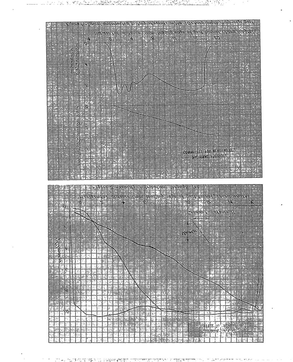
3 2...!l?hIsreport presents the results of gust-tunnel tests 1 scale model of the XBDR-1 with power off and also n a 17 the results of an analysis made to detemine the effective gust factor. The tests were made during October 1943 in the gust tunnel at Langley Field, Va., APPARATUS The gust tunnel.and auxiliary equipment have been described In reference scale model of the XBDR-1 airplane is shown e 17 in figure 1. Pertinent characteristics of the model as tested and of the full-scale airplane are given in table I. IX additiqn to geometric scaling of the airplane to reproduce the aerodynamic characteristics, the. weight and mass distributions were scaled as nearly as.. possible to obtain dynamic similarity. The data given in table I wqre obtatned from the ~terstate Aircraft and Engineering Corporation. The qlope of the lift curve, presented In table I was obtained from the results of force tests of the gust-tunnel model in the NACA freeflight tunnel. These results are given in figure 2. The three fist velocity distributions for ~h:ch the tests were made (gradient distance H = 0.75, and 17.5 chord lengths) were approximately lines; &d are shown on figure 3 as plots of the ratio of local mat velocity U- to the average maximum gust velocity ~=av against.the edge of the distance in chord lengths from the leading - gust tunnel. TESTS It was contemplated to fly the model with.two center-of-gravity positions (2L percent and 28 percent mean aerodynamic chord) for three gust gradients. However, in preliminary tests it was found that it was im-. possible to trim the model for steady gliding flight with the center of gravity at 24 percent mean aerodynamic chord. Since steady glidlng flight just before penetrating the gust is neoessary in order to obtain data
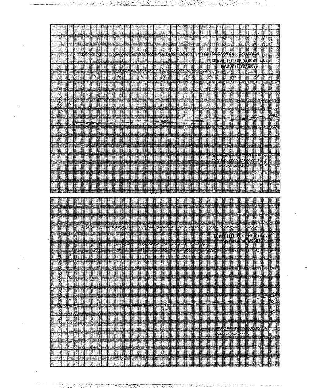
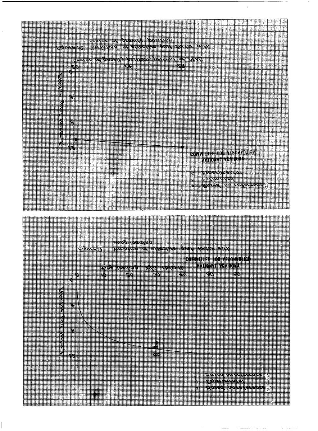
4 ~i. m :....,,......,--- :.,...., , :..,.. suitable for analysis, the test program was ohanged so thqt al% tests were made with the more stable center-of-..ll~qtity.po.8iti0nof 2Q peroent mean- aerodynami aohor& The stablllty of the model was Inoreased.sufftoiently by this oenter-of-gravity transition to,allbw the model to. be trinmed with the elevens. Foroe tests made Irithe NACA free-flight tunnel (fig. 2) showed that the neutral point was.at 24~percent mean aerodynamic chord. The. model was fltiithroughout the tests at a velocity corre-. spending to 182 tiles per hour (full scale) with an # eleven setting of.oo.. This was the maximum speed poaslble on the gust-tunnel apparatus. -,. :... The tests consisted of flights over the gust tunnel at fixed values of forward velocity and of average maximum gust velocity. A minimum offive flightswas made for each of the three gust gradients. Measurements of forward:velocity, gust velocity, normal acceleration increment, and pitch-angle increment were made during each flight : RESULTS. The records for all flights were evaluated to yield histories of the normal acceleration increment and pitch increment during the traverse of the gust. Sample results are shown In uncorrected form in figures 4, 5, and 6. The maximum acceleration increments fbr each flight went%.corrected for minor variations in gust velocity and forward velocity to the nominal values for the model given in table I.. The results are given In figure 7 plotted.against the gradient distance in.ohord lengths.. : n aooeleration ratio for.eaoh fllght,was obtained by divlding *e. imum acceleration inorement b the!: ~la~rp=edged-~~ Y ta~ielera~ion~,+ncre~nt ~s T referenoe 2).. A comparison of the experimental values with results obtained using the oonventlonal method of referenoe l-for oaloulatlon.of the acceleration ratios is shown in figure 8.,. Theekfeotlve gust faotor is taken as the ratio of the ameleratton r~ti~s of the XBDR-1 and B-247airplanes tn 8-and g-chord-length gusts, respectively. It has been determined that this dlscrepanoy in gust gradient
5 Qtstanoe tor all practloal purposes is negligible. The effective gust factors obtained In this manner are presented in ftgure 9 with the desire mrve shown in figure 1 of ref6renoii3 the method of ref=rence and a oaloti-atedvalue based on 4.. PRECISION The measured quantities are estimated to be accurate within the following limits for any single test or run: Acceleration Increment, g *0.05 Forward velocity, ft/sec. ~..., *0.5 Gust veloclty, ft/sec m**om.9*.* *0.1 Pitch-angle Increment, deg *0.5 ~ any given flight, minor variations in the launchlng speed, attitude, or setting of the model Introduce errors into the acceleration increment wliichare primarily a fumtion of the pitching motion of the model. In most cases the tendency was to pitch upward and then level off just prior to entry Into the gust. Sufflclent fllghts were made so that only flights with steady portions were used to evaluate results. Consideration of all the factors involved indfcates that the results from repeat flights should have a maximum dispersion of not more than ~0.15g for a gust with a gradient dtstance of chord lengths and to.08g for a gust with a gradient distance of 8 chord lengths. DISCUSSION The results as shown In figure 9 indtcate that, for the model In the stable condition as tested, the conventtonal theory Ylelds substantially correct results and that the effeot~ve gust faotor (alleviation factor K) of reference 3 Is satisfactory for use In the design of thla airplane for these oondltlons. As given in table I, the range of center-of-gravity positions for the full-scale airplane was farther aft. For the more aft center-ofgravity positions, adverse pitching motion due to the gust may oause an Increase in the effective gust factor. AS previously mentioned, it was impractical to fly the model with farther aft center-of-gravity positions,
6 . Therefore, for these conditions an analysis based on reference 4, whioh includes the effect of pitohing motion, was mad? to-determine the qffect.of..the-oenter-of-gravity posltlon on the effeotive gust f aotoro -s anaxysis differs from reference 4 only in that the stabilizer terms were omitted.. Consideration of the XBDR-1 configuration indicated that the conventional unsteady llft curves oould not be used due to the difference in the rate of development of lift at the root and tip and the gradual penetration of the oomplete airplane in the gust as the result of sweepback. ~ order to include these effeots, the infinite aspect-ratio curves of Kissner and V?aguer,as obtained from reference 5,were used with strip theory to obtain unsteady lift functions for the oamplete airplane including the variation In wing pitching moment due to the gradual penetration of a gust.. Comparison of the results of the analysis with experimental values is shown in figures 7, 8, and 9. The variation of the effective.gust faotor with center-ofgravity position for an 8-ohord-length gust,as obtained from this analysis,is shown in figure 10. From this figure it is evident that the analysis indicates an appreciable change In effective gust factor with the center-ofgravlty position. In view of the agreement obtained with test results by the analysis for the 20-percent center-of-gravity position and lacking experimental verification for other points, it is felt that the results of the analysis shown in figure 10 should be used as a basis for design. As previously mentioned, it was felt that the various rates of development of lift along the span might influenoe the wing bending moment. Therefore, a brief analysis based on strip theory was made of the effeot on the bending moment of these rates of development of lift as governed by the degree of sweepback and taper existing on the XBDR-1 Wing. The results of this analysis indicated that the effect was negligible. 5 CONCLUSIONS The test results and analysis were in good agreement, and the results of the analysis Indicated that there was
7 6- an appreciable change In effective gust faototifor the center-of-gravity movement considered. For the XRDR-1 with the.characteristics listed in table I, the value of the effective gust factor varies froiu1.08 for the 20-percent center-of-gravity position to 1.22 for the 28-peroent center-of-gravity position. It is recommended that a value of 1.22 be used for the effective gust faotor in the design of the XBDR-1 airplane. Langley Memorial Aeronautical Laboratory, National Advisory Committee for Aeronautics, Langley Field, Vs., February 3,
8 REFERENCES 1. Doriely;Philip: An Exper~ont~l In vest~gat~onof the Normal Aooeleratlon of an Atrplane Model in a Gust. NACA m NO. 706, Rhode Rlohard V.: (lustloads on Atrp18nea. Sfi Jour., vol. 40, no..s, Maroh 1937spp Rhode, Rtohard V., and Donely, PMlip; Frequency Ooourrence of Atmoapherio (lustsand of Related Loads on Airplane Struc$turea. NACA ARR NO. L@l, lbnely, Phlllp, Pieroe, Harold B., and Pepocxi,Phlllp w.s Measurements and Analysis of the Motion of a Canard Airplane Model NACA TN NO. 758, Jones, Robert T.: The Unsteady Lift of a Wing of Finite Aspeot Ratio. NACA Rep. No. 6&, 1*O. m..
9 TABLE T J. CHARACTERISTICS OF AIRPLAME MODEL Weight, lb , Wing area, sqft..o...0 m Wing loading, lb/sq ft Span, ft. o * Mean aerod-c ohord. ft.. * Center of &ravlty, per~ent M.A.C. Moment of Inertia mky2, slug-ft2 Slope of lift ourve, per radian. Gust velooity, ft/sec Forward velocity, mph.... Mass parameter M.. 1 I.... Ana~ g m. m 9 m 9* m m Model 2.2 ;:; i! * ii 9 93 m 2.9 a 1.2b XBDR-1 10, to ; 12 i ~

10 Figure l.- Gust-tunnelmodelofXBDR-1 airplane. ----

11 I
12 .

13 ~, , ,+
14 ..
15 .- --
16 .- Illlllllllml[flli[fl., ,>,,,. -5, \.-l
as NATIONAL ADVISORY COMMITTEE FOR AERONAUTICS oo- to-31 lg" '/ q TECHNICAL NOTE 1976 SUMMARY OF INFORMATION RELATING TO GUST
 NATIONAL ADVISORY COMMITTEE FOR AERONAUTICS TECHNICAL NOTE 1976 SUMMARY OF INFORMATION RELATING TO GUST LOADS ON AIRPLANES By Philip Donely,* Langley Aeronautical Laboratory Langley Air Force Base, Va.
Aircraft Design I Tail loads
 Horizontal tail loads Aircraft Design I Tail loads What is the source of loads? How to compute it? What cases should be taken under consideration? Tail small wing but strongly deflected Linearized pressure
PRINCIPLES OF FLIGHT
 1 Considering a positive cambered aerofoil, the pitching moment when Cl=0 is: A infinite B positive (nose-up). C negative (nose-down). D equal to zero. 2 The angle between the aeroplane longitudinal axis
Stability and Control Some Characteristics of Lifting Surfaces, and Pitch-Moments
 Stability and Control Some Characteristics of Lifting Surfaces, and Pitch-Moments The lifting surfaces of a vehicle generally include the wings, the horizontal and vertical tail, and other surfaces such
Aircraft Performance, Stability and control with experiments in Flight. Questions
 Aircraft Performance, Stability and control with experiments in Flight Questions Q. If only the elevator size of a given aircraft is decreased; keeping horizontal tail area unchanged; then the aircraft
Aeroelastic Gust Response
 Aeroelastic Gust Response Civil Transport Aircraft - xxx Presented By: Fausto Gill Di Vincenzo 04-06-2012 What is Aeroelasticity? Aeroelasticity studies the effect of aerodynamic loads on flexible structures,
RESEARCH MEMORANDUM NATIONAL ADVISORY COMMITTEE FOR AERONAUTICS UNCLASSIFIED AND DIRECTIONAL AERODYNAMIC CHARACTERISTICS OF FOUR
 " I RESEARCH MEMORANDUM SOME EFFECTS OF AILERON DEFLECTION ON THE STATIC LATERAL AND DIRECTIONAL AERODYNAMIC CHARACTERISTICS OF FOUR CONTEMPORARY AIRPLANE MODELS By Willard G. Smith and Peter F. Intrieri
MACH NUMBERS BETWEEN 0.8 AND 2.2 AS DETERMINED FROM THE
 NACA RM SL5kH2 NATIONAL ADVISORY COMMI'ITEE FOR AERONAUTICS RESEARCH MEMORANDUM for the Bureau of Aeronautics, Department of the Navy mo-lift DRAG OF THE CHANCE VOUGHT Rl3GULUS I1 MISSILE AT MACH NUMBERS
RESEARCH MEMORANDUM NATIONAL ADVISORY COMMITTEE FOR AERONAUTICS. -9:.f CANCELLED. . *..,t--:;.,q. By Edward C. Polhamus and Thomas J. Ring, Jr.
 RESEARCH MEMORANDUM AERODYNAMIC CIylRACTEmTICS WITH FEED AND FRcEE TRAN;SITION '",? f- I r\ t 7-1. *..,t--:;.,q OF A MODIFIED DELTA WINGIN COMBINATION WITH A FUSEIAGE AT EIGE SUBSONIC SPEEDS By Edward
w'..1 *s» NATIONAL ADVISORY COMMITTEE FOR AERONAUTICS ORIGINALLY ISSUED July 19^6 as Memorandum Eeport L6G12
 * - - if *s» w'..1»j*>s* # MR No. L6G12 NATIONAL ADVISORY COMMITTEE FOR AERONAUTICS ' V-i t 7J^»tf& l frfr" " A "]T*' ORIGINALLY ISSUED July 19^6 as Memorandum Eeport L6G12 A PEELEMIKAia* THEORETICAL STUDY
Contribution of Airplane design parameters on Roll Coupling اي داءالبارامترات التصميميه للطائره على ازدواج الحركي
 International Journal of Mechanical & Mechatronics Engineering IJMME-IJENS Vol:13 No:06 7 Contribution of Airplane design parameters on Roll Coupling اي داءالبارامترات التصميميه للطائره على ازدواج الحركي
Introduction to Aeronautics
 Introduction to Aeronautics ARO 101 Sections 03 & 04 Sep 30, 2015 thru Dec 9, 2015 Instructor: Raymond A. Hudson Week #8 Lecture Material 1 Topics For Week #8 Airfoil Geometry & Nomenclature Identify the
Transonic Aerodynamics Wind Tunnel Testing Considerations. W.H. Mason Configuration Aerodynamics Class
 Transonic Aerodynamics Wind Tunnel Testing Considerations W.H. Mason Configuration Aerodynamics Class Transonic Aerodynamics History Pre WWII propeller tip speeds limited airplane speed Props did encounter
NATIONAL ADVISORY COMMITTEE FOR AERONAUTICS
 NACALIBMRY" _ LANCLEY MEMORIAL AERQiiAUlicAi. LABORATORY _...- ILanofrv Pi*M V".7"'. NATIONAL ADVISORY COMMITTEE FOR AERONAUTICS TECHNICAL NOTE NLO. 1076 :- _ "-- A SIMPLIFIED METHOD FOR DETERMINING FROM
PRELIMINARY STUDY OF RELATIONSHIPS BETWEEN STABILITY AND CONTROL CHARACTERISTICS AND AFFORDABILITY FOR HIGH-PERFORMANCE AIRCRAFT
 AIAA-98-4265 PRELIMINARY STUDY OF RELATIONSHIPS BETWEEN STABILITY AND CONTROL CHARACTERISTICS AND AFFORDABILITY FOR HIGH-PERFORMANCE AIRCRAFT Marilyn E. Ogburn* NASA Langley Research Center Hampton, VA
Performance. 7. Aircraft Performance -Basics
 Performance 7. Aircraft Performance -Basics In general we are interested in finding out certain performance characteristics of a vehicle. These typically include: how fast and how slow an aircraft can
SPECIAL CONDITION. Water Load Conditions. SPECIAL CONDITION Water Load Conditions
 Doc. No. : SC-CVLA.051-01 Issue : 1d Date : 04-Aug-009 Page : 1 of 13 SUBJECT : CERTIFICATION SPECIFICATION : VLA.51 PRIMARY GROUP / PANEL : 03 (Structure) SECONDARY GROUPE / PANEL : -- NATURE : SCN VLA.51
TECHNICAL NOTES NATIONAL ADVISORY COMMITTEE FOR AERONAUTICS NO. 341
 L,,, TECHNCAL NOTES NATONAL ADVSORY COMMTTEE FOR AERONAUTCS NO 341 CALBRATON AND LAG OF A FREZ TYPE CUP ANEMOMETER By Robert M Pinkerton Langley Memorial Aeronauticd Laboratory A Washington June, 1930
Mechanics of Flight. Warren F. Phillips. John Wiley & Sons, Inc. Professor Mechanical and Aerospace Engineering Utah State University WILEY
 Mechanics of Flight Warren F. Phillips Professor Mechanical and Aerospace Engineering Utah State University WILEY John Wiley & Sons, Inc. CONTENTS Preface Acknowledgments xi xiii 1. Overview of Aerodynamics
April 15, 2011 Sample Quiz and Exam Questions D. A. Caughey Page 1 of 9
 April 15, 2011 Sample Quiz Exam Questions D. A. Caughey Page 1 of 9 These pages include virtually all Quiz, Midterm, Final Examination questions I have used in M&AE 5070 over the years. Note that some
Study. Aerodynamics. Small UAV. AVL Software
 Study of the Aerodynamics of a Small UAV using AVL Software Prepared For: Prof. Luis Bernal Prepared By: Paul Dorman April 24, 2006 Table of Contents Introduction.1 Aerodynamic Data...2 Flight Assessment..
Limit Cycle Oscillations of a Typical Airfoil in Transonic Flow
 Limit Cycle Oscillations of a Typical Airfoil in Transonic Flow Denis B. Kholodar, United States Air Force Academy, Colorado Springs, CO 88 Earl H. Dowell, Jeffrey P. Thomas, and Kenneth C. Hall Duke University,
MODIFICATION OF AERODYNAMIC WING LOADS BY FLUIDIC DEVICES
 Journal of KONES Powertrain and Transport, Vol. 21, No. 2 2014 MODIFICATION OF AERODYNAMIC WING LOADS BY FLUIDIC DEVICES Institute of Aviation Department of Aerodynamics and Flight Mechanics Krakowska
Research on Propeller Characteristics of Tip Induced Loss
 4th International Conference on Machinery, Materials and Information Technology Applications (ICMMITA 2016) Research on Propeller Characteristics of Tip Induced Loss Yang Song1, a, Peng Shan2, b 1 School
firmed Services Technical Information Agenc)
") F Reproduced 6y firmed Services Technical Information Agenc) DOCUMENT SERVICE CENTER KNOTT BUILDING, DAYTON, 2, OHIO I- - Hib I TLNIASF D -NATIONAL ADVISORY COMMITTEE,.FOR AERONAUTICS TECHNICAL NOTE 2923
F Reproduced 6y firmed Services Technical Information Agenc) DOCUMENT SERVICE CENTER KNOTT BUILDING, DAYTON, 2, OHIO I- - Hib I TLNIASF D -NATIONAL ADVISORY COMMITTEE,.FOR AERONAUTICS TECHNICAL NOTE 2923
Extended longitudinal stability theory at low Re - Application to sailplane models
 Extended longitudinal stability theory at low Re - Application to sailplane models matthieu.scherrer@free.fr November 26 C L C m C m W X α NP W X V NP W Lift coefficient Pitching moment coefficient Pitching
Dynamic Response of an Aircraft to Atmospheric Turbulence Cissy Thomas Civil Engineering Dept, M.G university
 Dynamic Response of an Aircraft to Atmospheric Turbulence Cissy Thomas Civil Engineering Dept, M.G university cissyvp@gmail.com Jancy Rose K Scientist/Engineer,VSSC, Thiruvananthapuram, India R Neetha
AIRFOIL DESIGN PROCEDURE A MODIFIED THEODORSEN E-FUNCTION. by Raymond L. Barger. Langley Research Center NASA TECHNICAL NOTE NASA TN D-7741
 NASA TECHNICAL NOTE NASA TN D-7741 AND 1- I- 6~7 (NASA-TN-D-7741) A MODIFIED THEODORSEN N74-33428 EPSILON-FUNCTION AIRFOIL DESIGN PROCEDURE (NASA) 19 p BC $3.00 CSCL 01A Unclas H1/01 48910 rr A MODIFIED
Aero-Propulsive-Elastic Modeling Using OpenVSP
 Aero-Propulsive-Elastic Modeling Using OpenVSP August 8, 213 Kevin W. Reynolds Intelligent Systems Division, Code TI NASA Ames Research Center Our Introduction To OpenVSP Overview! Motivation and Background!
Flight Dynamics and Control. Lecture 3: Longitudinal stability Derivatives G. Dimitriadis University of Liege
 Flight Dynamics and Control Lecture 3: Longitudinal stability Derivatives G. Dimitriadis University of Liege Previously on AERO0003-1 We developed linearized equations of motion Longitudinal direction
Aircraft Structures Design Example
 University of Liège Aerospace & Mechanical Engineering Aircraft Structures Design Example Ludovic Noels Computational & Multiscale Mechanics of Materials CM3 http://www.ltas-cm3.ulg.ac.be/ Chemin des Chevreuils
RESEARCH MEMORANDUM. JUL3 1%-i NATIONAL ADVISORY COMMITTEE. 8 Langley Aeronautical Laboratory Langley Ffeld$XASSIFICATION CHANGED
 03 0 w r-l t- z JUL3 1%-i RESEARCH MEMORANDUM LFT AND DRAG COEFFCENTS FOR THE BELL X-1 ARPLANE (8-PEFCEN"TEUCK WNG) N POWER-OFF 3 TFUWSONC FLGHT By L. Robert Carman and John R. Carden B 8 Langley Aeronautical
INSTITUTE OF AERONAUTICAL ENGINEERING (Autonomous) Dundigal, Hyderabad
 Dundigal, Hyderabad") INSTITUTE OF AERONAUTICAL ENGINEERING (Autonomous) Dundigal, Hyderabad - 500 043 AERONAUTICAL ENGINEERING TUTORIAL QUESTION BANK Course Name : LOW SPEED AERODYNAMICS Course Code : AAE004 Regulation : IARE
INSTITUTE OF AERONAUTICAL ENGINEERING (Autonomous) Dundigal, Hyderabad - 500 043 AERONAUTICAL ENGINEERING TUTORIAL QUESTION BANK Course Name : LOW SPEED AERODYNAMICS Course Code : AAE004 Regulation : IARE
THE EFFECT OF WING GEOMETRY ON LIFT AT SUPERSONIC SPEEDS
 Journal of Engineering Science and Technology EURECA 2013 Special Issue August (2014) 16-27 School of Engineering, Taylor s University THE EFFECT OF WING GEOMETRY ON LIFT AT SUPERSONIC SPEEDS ABDULKAREEM
TECHNICAL NOTE 4006 INVESTIGATION AT TRANSONIC SPEEDS OF DEFLECTORS AND SPOILERS AS GUST ALLEVMTORS ON A 35 SWEPT WING TRANSOIWC -BUMP
 TECHNICAL NOTE 4006 INVESTIGATION AT TRANSONIC SPEEDS OF DEFLECTORS AND SPOILERS AS GUST ALLEVMTORS ON A 35 SWEPT WING TRANSOIWC -BUMP METHOD By Delwh R Croorn md Jarrett K Huffman Langley Aeronautical
4-7. Elementary aeroelasticity
 a Aeroelasticity Dynamic... Dynamic Static stability... Static 4-7 Istability Load Divergence Control Flutter Buffeting Dynamic distribution reversal response Elementary aeroelasticity Aircraft structures,
RESEARCH MEMORANDUM FUGHT CHARACTERSSTICS OF A WINGIZSS ROCKET-POWERED MODEL WITH FOUR EXTERNALLY MOUNTED AIR-TO-APR MISSILES,$ Langley.Field, Va.
 3 1176 6 693 i RESEARCH MEMORANDUM FUGHT CHARACTERSSTCS OF A WNGZSS ROCKET-POWERED MODEL 'r- WTH FOUR EXTERNALLY MOUNTED AR-TO-APR MSSLES,$ AT MACH NUMBERS FROM.7 TO 1.6 By Allen B. Henning and Clarence
Effect of Moment of Inertia and Aerodynamics Parameters on Aerodynamic Coupling in Roll Mode
 Parameters on Aerodynamic Coupling in Roll Raed Abbas Jessam Electromechanical Engineering Department, University of Technology/ Baghdad Email:- ra_tb2006@yahoo.com Received on: 19/6 /2011 & Accepted on:
University of California at Berkeley Department of Mechanical Engineering ME 163 ENGINEERING AERODYNAMICS FINAL EXAM, 13TH DECEMBER 2005
 University of California at Berkeley Department of Mechanical Engineering ME 163 ENGINEERING AERODYNAMICS FINAL EXAM, 13TH DECEMBER 2005 Answer both questions. Question 1 is worth 30 marks and question
Lecture-4. Flow Past Immersed Bodies
 Lecture-4 Flow Past Immersed Bodies Learning objectives After completing this lecture, you should be able to: Identify and discuss the features of external flow Explain the fundamental characteristics
Aerodynamics SYST 460/560. George Mason University Fall 2008 CENTER FOR AIR TRANSPORTATION SYSTEMS RESEARCH. Copyright Lance Sherry (2008)
") Aerodynamics SYST 460/560 George Mason University Fall 2008 1 CENTER FOR AIR TRANSPORTATION SYSTEMS RESEARCH Copyright Lance Sherry (2008) Ambient & Static Pressure Ambient Pressure Static Pressure 2 Ambient
Aerodynamics SYST 460/560 George Mason University Fall 2008 1 CENTER FOR AIR TRANSPORTATION SYSTEMS RESEARCH Copyright Lance Sherry (2008) Ambient & Static Pressure Ambient Pressure Static Pressure 2 Ambient
AE 714 Aeroelastic Effects in Structures Term Project (Revised Version 20/05/2009) Flutter Analysis of a Tapered Wing Using Assumed Modes Method
 Flutter Analysis of a Tapered Wing Using Assumed Modes Method") AE 714 Aeroelastic Effects in Structures Term Project (Revised Version 20/05/2009) Flutter Analysis of a Tapered Wing Using Assumed Modes Method Project Description In this project, you will perform classical
AE 714 Aeroelastic Effects in Structures Term Project (Revised Version 20/05/2009) Flutter Analysis of a Tapered Wing Using Assumed Modes Method Project Description In this project, you will perform classical
Stability and Control Analysis in Twin-Boom Vertical Stabilizer Unmanned Aerial Vehicle (UAV)
") International Journal of Scientific and Research Publications, Volume 4, Issue 2, February 2014 1 Stability and Control Analysis in Twin-Boom Vertical Stabilizer Unmanned Aerial Vehicle UAV Lasantha Kurukularachchi*;
International Journal of Scientific and Research Publications, Volume 4, Issue 2, February 2014 1 Stability and Control Analysis in Twin-Boom Vertical Stabilizer Unmanned Aerial Vehicle UAV Lasantha Kurukularachchi*;
AERODYNAMIC COEFFICIENTS FOR EXTENDING AND BENDING PROJECTILES. William G. Reinecke*
 23 RD INTERNATIONAL SYMPOSIUM ON BALLISTICS TARRAGONA, SPAIN 16-20 APRIL 2007 AERODYNAMIC COEFFICIENTS FOR EXTENDING AND BENDING PROJECTILES William G. Reinecke* Institute for Advanced Technology.The University
Chapter 5 Wing design - selection of wing parameters 2 Lecture 20 Topics
 Chapter 5 Wing design - selection of wing parameters Lecture 0 Topics 5..4 Effects of geometric parameters, Reynolds number and roughness on aerodynamic characteristics of airfoils 5..5 Choice of airfoil
Drag (2) Induced Drag Friction Drag Form Drag Wave Drag
 Induced Drag Friction Drag Form Drag Wave Drag") Drag () Induced Drag Friction Drag Form Drag Wave Drag Outline Nomenclature and Concepts Farfield Drag Analysis Induced Drag Multiple Lifting Surfaces Zero Lift Drag :Friction and Form Drag Supersonic
Drag () Induced Drag Friction Drag Form Drag Wave Drag Outline Nomenclature and Concepts Farfield Drag Analysis Induced Drag Multiple Lifting Surfaces Zero Lift Drag :Friction and Form Drag Supersonic
'FOR 'AERONAUTICS LATERAL STABILITY CHARACTERISTICS BETWEEN...~ .MACH:NUMBERS OF 0.80 AND 1.57 A N D, SiMULATION OF COUPLED
 ......,~,.............,. LATERAL STABILITY CHARACTERISTICS BETWEEN...~.MACH:NUMBERS OF 0.80 AND 1.57 A N D, SiMULATION OF COUPLED.......,,.............. MOTION AT MACH NUMBER 1.30 OF A ROCKET-PROPELLED
APPENDIX C DRAG POLAR, STABILITY DERIVATIVES AND CHARACTERISTIC ROOTS OF A JET AIRPLANE (Lectures 37 to 40)
") APPENDIX C DRAG POLAR, STABILITY DERIVATIVES AND CHARACTERISTIC ROOTS OF A JET AIRPLANE (Lectures 37 to 40 E.G. TULAPURKARA YASHKUMAR A. VENKATTRAMAN REPORT NO: AE TR 2007-3 APRIL 2007 (REVISED NOVEMBER
APPENDIX C DRAG POLAR, STABILITY DERIVATIVES AND CHARACTERISTIC ROOTS OF A JET AIRPLANE (Lectures 37 to 40 E.G. TULAPURKARA YASHKUMAR A. VENKATTRAMAN REPORT NO: AE TR 2007-3 APRIL 2007 (REVISED NOVEMBER
Fundamentals of Airplane Flight Mechanics
 David G. Hull Fundamentals of Airplane Flight Mechanics With 125 Figures and 25 Tables y Springer Introduction to Airplane Flight Mechanics 1 1.1 Airframe Anatomy 2 1.2 Engine Anatomy 5 1.3 Equations of
Introduction to Flight Dynamics
 Chapter 1 Introduction to Flight Dynamics Flight dynamics deals principally with the response of aerospace vehicles to perturbations in their flight environments and to control inputs. In order to understand
EVOLVING DOCUMENT ME 5070 Flight Dynamics
 EVOLVING DOCUMENT ME 5070 Flight Dynamics Homework Date of this version: March 20, 2015 Hyperlinks look like this Dates in headings below are the dates of the associated lecture Due January 27, 2015 1
NATIONAL ADVISORY COMMITTEE FOR AERONAUTICS WARTIME REPORT. ORIGINALLY ISSUED September 19^5 as Restricted BuHetin L5F27
 i I. LJ A=, 'U KB No. L5F27 NATIONAL ADVISORY COMMITTEE FOR AERONAUTICS WARTIME REPORT ORIGINALLY ISSUED September 19^5 as Restricted BuHetin L5F27 AN APPROXIMATE EETEERMEKATION OF THE POWER REQUIRED TO
Flight Vehicle Terminology
 Flight Vehicle Terminology 1.0 Axes Systems There are 3 axes systems which can be used in Aeronautics, Aerodynamics & Flight Mechanics: Ground Axes G(x 0, y 0, z 0 ) Body Axes G(x, y, z) Aerodynamic Axes
AN ENGINEERING LEVEL PREDICTION METHOD FOR NORMAL-FORCE INCREASE DUE TO WEDGE SECTIONS
 27 TH INTERNATIONAL CONGRESS OF THE AERONAUTICAL SCIENCES AN ENGINEERING LEVEL PREDICTION ETHOD FOR NORAL-FORCE INCREASE DUE TO WEDGE SECTIONS Asher Sigal Shehafim R&D, Haifa 34861, Israel Keywords: wedge
Experimental Studies on Complex Swept Rotor Blades
 International Journal of Engineering Research and Technology. ISSN 974-3154 Volume 6, Number 1 (213), pp. 115-128 International Research Publication House http://www.irphouse.com Experimental Studies on
Study of Preliminary Configuration Design of F-35 using simple CFD
 Study of Preliminary Configuration Design of F-35 using simple CFD http://www.aerospaceweb.org/aircraft/research/x35/pics.shtml David Hall Sangeon Chun David Andrews Center of Gravity Estimation.5873 Conventional
Consider a wing of finite span with an elliptic circulation distribution:
 Question 1 (a) onsider a wing of finite span with an elliptic circulation distribution: Γ( y) Γo y + b = 1, - s y s where s=b/ denotes the wing semi-span. Use this equation, in conjunction with the Kutta-Joukowsky
March No In Cooperation with the University of Wisconsin
 March 1956 No. In Cooperation with the University of Wisconsin STRESSES IN WOOD MEMBERS SUBJECTED TO COMBINED COLUMN AND BEAM ACTION.* J. A. NEWLIN and G. W. TRAYER. INTRODUCTION. This publication is one
TECHNICAL NOTE D ABLATING UNDER CONSTANT AERODYNAMIC CONDITIONS. By Robert R. Howell. Langley Research Center Langley Station, Hampton, Va.
 -. NASA TN D-1635 TECHNICAL NOTE 1 D- 1635 AN EXPERIMENTAL STUDY OF THE BEHAVIOR OF SPHERES ABLATING UNDER CONSTANT AERODYNAMIC CONDITIONS By Robert R. Howell Langley Research Center Langley Station, Hampton,
( ) (where v = pr ) v V
 (where v = pr ) v V") Problem # The DOF idealized wing whose cross-section is shown in Figure. has leading edge and trailing edge control surfaces. There is no initial angle of attack when the two control surfaces are undeflected.
Problem # The DOF idealized wing whose cross-section is shown in Figure. has leading edge and trailing edge control surfaces. There is no initial angle of attack when the two control surfaces are undeflected.
Numerical Simulation of Unsteady Aerodynamic Coefficients for Wing Moving Near Ground
 ISSN -6 International Journal of Advances in Computer Science and Technology (IJACST), Vol., No., Pages : -7 Special Issue of ICCEeT - Held during -5 November, Dubai Numerical Simulation of Unsteady Aerodynamic
AIAA Sensing Aircraft Effects by Flap Hinge Moment Measurement
 AIAA 99-349 Sensing Aircraft Effects by Flap Hinge Moment Measurement Holly M. Gurbacki and Michael B. Bragg University of Illinois at Urbana-Champaign Urbana, IL 7th Applied Aerodynamics Conference June
A FIGHTER AIRPLANE. Langley Aeronautical Laboratory Langley Field, Va. CLASSIFIED WCUb4ENT..
 . CON FI DENTIAL COPY fz RM L56G06 $2' mx! - %""d a ' HORIZONTAL' A FIGHTER AIRPLANE By Norman Frank T. Abbott, Jr. / Langley Aeronautical Laboratory Langley Field, Va. CLASSIFIED WCUb4ENT.. TNS material
NATIONALADVISORY COMMITTEE FOR AERONAUTICS TECHNICAL NOTE 2741 INVESTIGATION OF THE INFLUENCE OF FUSELAGE AND TAIL
 : I NATIONALADVISORY COMMITTEE FOR AERONAUTICS TECHNICAL NOTE 2741 INVESTIGATION OF THE INFLUENCE OF FUSELAGE AND TAIL SURFACES ON LOW-SPEED STATIC STABILITY AND ROLLING CHARACTERISTICS, 1 OF A SWEPT-WING
Aircraft stability and control Prof: A. K. Ghosh Dept of Aerospace Engineering Indian Institute of Technology Kanpur
 Aircraft stability and control Prof: A. K. Ghosh Dept of Aerospace Engineering Indian Institute of Technology Kanpur Lecture- 05 Stability: Tail Contribution and Static Margin (Refer Slide Time: 00:15)
MAV Unsteady Characteristics in-flight Measurement with the Help of SmartAP Autopilot
 MAV Unsteady Characteristics in-flight Measurement with the Help of SmartAP Autopilot S. Serokhvostov, N. Pushchin and K. Shilov Moscow Institute of Physics and Technology Department of Aeromechanics and
Optimal Pitch Thrust-Vector Angle and Benefits for all Flight Regimes
 NASA/TM-2000-209021 Optimal Pitch Thrust-Vector Angle and Benefits for all Flight Regimes Glenn B. Gilyard Dryden Flight Research Center Edwards, California Alexander Bolonkin Senior Research Associate
AE Stability and Control of Aerospace Vehicles
 AE 430 - Stability and ontrol of Aerospace Vehicles Static/Dynamic Stability Longitudinal Static Stability Static Stability We begin ith the concept of Equilibrium (Trim). Equilibrium is a state of an
The Truth About Elliptic Spanloads or Optimum Spanloads Incorporating Wing Structural Weight
 The Truth About Elliptic Spanloads or Optimum Spanloads Incorporating Wing Structural Weight Sergio Iglesias and William H. Mason AIAA Paper 2001-5234 as presented at the 1st AIAA Aircraft Technology,
MODELING OF SPIN MODES OF SUPERSONIC AIRCRAFT IN HORIZONTAL WIND TUNNEL
 24 TH INTERNATIONAL CONGRESS OF THE AERONAUTICAL SCIENCES MODELING OF SPIN MODES OF SUPERSONIC AIRCRAFT IN HORIZONTAL WIND TUNNEL Federal State Unitary Enterprise «Siberian Aeronautical Research Institute»
EFFECT OF SIDESLIP ANGLE ON THE BALANCE OF AIRCRAFT MOMENTS THROUGH STEADY - STATE SPIN
 International Journal of Civil Engineering Technology (IJCIET) Volume 8, Issue 10, October 2017, pp. 627 633, Article ID: IJCIET_08_10_065 Available online at http://http://www.iaeme.com/ijciet/issues.asp?jtype=ijciet&vtype=8&itype=10
Stability and Control
 Stability and Control Introduction An important concept that must be considered when designing an aircraft, missile, or other type of vehicle, is that of stability and control. The study of stability is
The future of non-linear modelling of aeroelastic gust interaction
 The future of non-linear modelling of aeroelastic gust interaction C. J. A. Wales, C. Valente, R. G. Cook, A. L. Gaitonde, D. P. Jones, J. E. Cooper University of Bristol AVIATION, 25 29 June 2018 Hyatt
Reduced reliance on wind tunnel data
 Reduced reliance on wind tunnel data The recreation of the industrial gust loads process, using CFD in place of experimental data Investigation of the underlying assumptions of the current industrial gust
EVALUATION OF TRANSONIC BUFFETING ONSET BOUNDARY ESTIMATED BY TRAILING EDGE PRESSURE DIVERGENCE AND RMS DATA OF WING VIBRATION
 EVALUATION OF TRANSONIC BUFFETING ONSET BOUNDARY ESTIMATED BY TRAILING EDGE PRESSURE DIVERGENCE AND RMS DATA OF WING VIBRATION Rodrigo Sorbilli C. de Sousa, Roberto da Motta Girardi Roberto Gil Annes da
WASHINGTON April 20, 1955
 I FLIGHT MEASUREMENTS AT TRANSONIC SPEEDS OF THE BUFFETING CHAMCTERISTICS OF THE XF-92A DELTA-WING RESEARCH AIRPLANE By Thomas F. Baker and Wallace E. Johnson WASHINGTON April 20, 1955 TECH LIBRARY KAFB,
Wind Tunnel Study of a Large Aerostat, CFD Validation
 AIAA Lighter-Than-Air Systems Technology (LTA) Conference 25-28 March 2013, Daytona Beach, Florida AIAA 2013-1339 Wind Tunnel Study of a Large Aerostat, CFD Validation Stephen C. Chan 1, Kaleb Shervington
FREQUENCY DOMAIN FLUTTER ANALYSIS OF AIRCRAFT WING IN SUBSONIC FLOW
 FREQUENCY DOMAIN FLUTTER ANALYSIS OF AIRCRAFT WING IN SUBSONIC FLOW Ms.K.Niranjana 1, Mr.A.Daniel Antony 2 1 UG Student, Department of Aerospace Engineering, Karunya University, (India) 2 Assistant professor,
Air Loads. Airfoil Geometry. Upper surface. Lower surface
 AE1 Jha Loads-1 Air Loads Airfoil Geometry z LE circle (radius) Chord line Upper surface thickness Zt camber Zc Zl Zu Lower surface TE thickness Camber line line joining the midpoints between upper and
High Speed Aerodynamics. Copyright 2009 Narayanan Komerath
 Welcome to High Speed Aerodynamics 1 Lift, drag and pitching moment? Linearized Potential Flow Transformations Compressible Boundary Layer WHAT IS HIGH SPEED AERODYNAMICS? Airfoil section? Thin airfoil
 RM -L7G02
 A HARMONIC BALANCE APPROACH FOR MODELING THREE-DIMENSIONAL NONLINEAR UNSTEADY AERODYNAMICS AND AEROELASTICITY
 ' - ' Proceedings of ASME International Mechanical Engineering Conference and Exposition November 17-22, 22, New Orleans, Louisiana, USA IMECE-22-3232 A HARMONIC ALANCE APPROACH FOR MODELING THREE-DIMENSIONAL
R,ESEARCH MEMORANDUM for the Bureau of Aeronautics, Department of.the Navy
 RM SL55BO9 R,ESEARCH MEMORANDUM for the Bureau of Aeronautics, Department of.the Navy FREE-SPNNNGTUN?BL NVESTGA'?ON TO DETERMNE 'THfZ EFFECT OF SPN-RECOVERY ROCK@TS,AND THRUST SMULATOti ON THE RECOVEtiY
Study on Numerical Simulation Method of Gust Response in Time Domain Jun-Li WANG
 International Conference on Mechanics and Civil Engineering (ICMCE 4) Study on Numerical Simulation Method of Gust Response in Time Domain Jun-Li WANG School of Mechanical Engineering, Shaanxi University
DEPARTMENT OF AEROSPACE ENGINEERING, IIT MADRAS M.Tech. Curriculum
 DEPARTMENT OF AEROSPACE ENGINEERING, IIT MADRAS M.Tech. Curriculum SEMESTER I AS5010 Engg. Aerodyn. & Flt. Mech. 3 0 0 3 AS5020 Elements of Gas Dyn. & Propln. 3 0 0 3 AS5030 Aircraft and Aerospace Structures
DEFLECTION OF BEAMS WlTH SPECIAL REFERENCE TO SHEAR DEFORMATIONS
 DEFLECTION OF BEAMS WlTH SPECIAL REFERENCE TO SHEAR DEFORMATIONS THE INFLUENCE OF THE FORM OF A WOODEN BEAM ON ITS STIFFNESS AND STRENGTH-I (REPRINT FROM NATIONAL ADVISORY COMMITTEE FOR AERONAUTICS REPORT
Improved Method for Prediction of Attainable Wing Leading-Edge Thrust
 NASA Technical Paper 3557 Improved Method for Prediction of Attainable Wing Leading-Edge Thrust Harry W. Carlson Lockheed Engineering & Sciences Company Hampton, Virginia Marcus O. McElroy and Wendy B.
Mechanics. Flight Lessons 1: Basic Flight. Position, starting with 2 dimensions
 Position, starting with 2 dimensions Mechanics We can measure our position forward with positive numbers and backwards with negative numbers. The bike is at 0. Speed (Average) If we take two odometer readings,
Milestone 1: Aircraft Design
 Iowa State University AerE 294X/AerE 494X Make to Innovate Milestone 1: Aircraft Design Author(s): Joshua Buettner Joseph Cairo Michael Londergan Jose Montesinos Theodore Permula Samuel Ruhlin Project:
Given the water behaves as shown above, which direction will the cylinder rotate?
 water stream fixed but free to rotate Given the water behaves as shown above, which direction will the cylinder rotate? ) Clockwise 2) Counter-clockwise 3) Not enough information F y U 0 U F x V=0 V=0
Analysis of Wind Tunnel Oscillatory Data of the X-31A Aircraft
 NASA/CR-999-28725 Analysis of Wind Tunnel Oscillatory Data of the X-3A Aircraft Mark S. Smith The George Washington University Joint Institute for Advancement of Flight Sciences Langley Research Center,
A Simple Analysis of Fuel Addition to the CWT of 747
 A Simple Analysis of Fuel Addition to the CWT of 747 Raza Akbar and Joseph E. Shepherd Graduate Aeronautical Laboratories California Institute of Technology Pasadena, CA 91125 USA 21 September 1998 Sponsored
Aerodynamics and Flight Mechanics
 Aerodynamics and Flight Mechanics Principal Investigator: Mike Bragg Eric Loth Post Doc s: Graduate Students: Undergraduate Students: Sam Lee Jason Merret Kishwar Hossain Edward Whalen Chris Lamarre Leia
Introduction to Aerospace Engineering
 Introduction to Aerospace Engineering 5. Aircraft Performance 5.1 Equilibrium Flight In order to discuss performance, stability, and control, we must first establish the concept of equilibrium flight.
NATIONALADVISORY COMMITTEE FOR AERONAUTICS TECHNICAL NOTE 4214 AT MACH 3.1. Paul F. Brinich. Flight Propulsion Laboratory Cleveland, Ohio.
 r NATONALADVSORY COMMTTEE FOR AERONAUTCS TECHNCAL NOTE 4214 BOUNDARY -LAYER TRANSTON ON AN OPEN -NOSE CONE AT MACH 3.1 By Paul F. Brinich Lewis Flight Propulsion Laboratory Cleveland, Ohio =w= Washington
CHAPTER 3 ANALYSIS OF NACA 4 SERIES AIRFOILS
 54 CHAPTER 3 ANALYSIS OF NACA 4 SERIES AIRFOILS The baseline characteristics and analysis of NACA 4 series airfoils are presented in this chapter in detail. The correlations for coefficient of lift and
The S411, S412, and S413 Airfoils
 RDECOM TR 10-D-110 U.S. ARMY RESEARCH, DEVELOPMENT AND ENGINEERING COMMAND TITLE: AUTHOR: COMPANY NAME: COMPANY ADDRESS: The S411, S412, and S413 Airfoils Dan M. Somers Airfoils, Incorporated 122 Rose
Reynolds Number Effects on the Performance of Lateral Control Devices
 NASA/TM-2-21541 Reynolds Number Effects on the Performance of Lateral Control Devices Raymond E. Mineck Langley Research Center, Hampton, Virginia October 2 The NASA STI Program Office... in Profile Since
Evaluation of the Drag Reduction Potential and Static Stability Changes of C-130 Aft Body Strakes
 U.S. Air Force T&E Days 2009 10-12 February 2009, Albuquerque, New Mexico AIAA 2009-1721 Evaluation of the Drag Reduction Potential and Static Stability Changes of C-130 Aft Body Strakes Heather G. Pinsky
13 Nov 1947 MRJuly 1940 NATIONAL ADVISORY COMMITTEE FOR AERONAUTICF ORIGINALLY I SUED. July as Memorandum Report
 13 Nov 1947 MRJuly 1940.,..... NATIONAL ADVISORY COMMITTEE FOR AERONAUTICF ORIGINALLY I SUED July 194 8 as Memorandum Report & EXPERIMENTAL INVESTIGATION TO DETERMINE THE RELATIVE MAGNITUDE OF VERTICAL